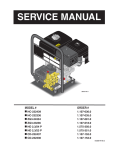
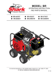
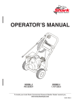
1
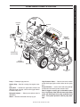
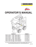
Model: DG
operating instruction
and parts manual
■ DG-2323
■ DG-3532
CH
AU
■ DG-2324
■ DG-3835
■ DG-2527
■ DG-2123
■ DG-3030
D!
Re
ad
lIR
oW
e
Ne
vo le
R'S
be R IN MaNU Ma
dI
No eNbeTR el NUal
UT UN Ieb d'U
IlI GS Na TIl befo
za aN hM ISa
Re
R
le
SIN ITUe UN TeUR op
aN NG be
av eR
Te
dU dING aN aTIo
S No
T US N.
RS
T
ha Chle
aG
be
e.
R SeN.
le
Id
o
el
Ma
NU
al
eR
T
.
al
ly
W, Te
oIl
l lo dIa
veIMMe
l le S
oI op
eN ST
WhGINe
eN
.
For technical assistance or the SHARK dealer nearest you
visit our website at www.shark-pw.com
8.914-450.0 / 97-720
CONTENTS
Important Safety Information.................................................................3-4
Component Identification.......................................................................... 5
Assembly Instructions............................................................................... 6
Operating Instructions...........................................................................7-8
Applying Detergent and General Operating Techniques........................... 9
Shut Down and Clean-Up....................................................................... 10
Storage................................................................................................... 10
Troubleshooting.................................................................................11-12
Preventative Maintenance...................................................................... 13
Oil Change Record................................................................................. 13
Exploded View........................................................................................ 14
Exploded View Parts List...................................................................15-16
Vertical Exploded View........................................................................... 17
Vertical Exploded view Parts List............................................................ 18
Specifications.......................................................................................... 19
G1 Pump w/1" Hollow Shaft Exploded View and Parts List...............20-21
G Pump w/3/4" Hollow Shaft Exploded View and Parts List..............22-23
HS-1 Pump Exploded View and Parts List.........................................24-25
FAIP 5-1100 Pump Exploded View and Parts List.............................26-27
9.120-032.0 Pump Exploded Views and Parts Lists..........................28-29
VBA35 Unloader Exploded View and Parts List..................................... 30
Warranty
Model Number ______________________________
Serial Number ______________________________
Date of Purchase ____________________________
The model and serial numbers will be found on a decal attached
to the pressure washer. You should record both serial number and
date of purchase and keep in a safe place for future reference.
96-716, 97-718, 97-720 • Rev. 7/07
Thank you for purchasing this Pressure Washer.
We reserve the right to make changes at any time
without incurring any obligation.
Owner/User Responsibility:
Owner and/or user must study and maintain for future
reference the manufacturers’ instructions.
The operator must know how to stop the machine
quickly and understand the operation of all controls.
Never permit anyone to operate the engine without
proper instructions.
This manual should be considered a permanent
part of the machine and should remain with it if
machine is resold.
When ordering parts, please specify model and
serial number. Use only identical replacement
parts.
This machine is to be used only by trained operators.
Important Safety
Information
WARNING: To reduce the risk of
injury, read operating instructions carefully before using.
1.Read the owner's manual
thoroughly. Failure to follow
instructions could cause malfunction of the machine and
read operator’s
manual thoroughly
result in death, serious bodily
prior to use.
injury and/or property damage.
2. Know how to stop the machine and bleed pressure
quickly. Be thoroughly familiar with the controls.
3.Stay alert — watch what you are doing.
4.All installations must comply with local codes.
Contact your electrician, plumber, utility company
or the selling distributor for specific details.
OPERATOR’S MANUAL
The owner and/or user must have an understanding of
the manufacturer’s operating instructions and warnings
before using this pressure washer. Warning information
should be emphasized and understood. If the operator
is not fluent in English, the manufacturer’s instructions
and warnings shall be read to and discussed with
the operator in the operator’s native language by the
purchaser/owner, making sure that the operator comprehends its contents.
WaRNING WARNING: Risk of asphyxiation.
Use this product only in a well
ventilated area.
5.Avoid installing machines in
small areas or near exhaust
fans. Exhaust contains poirisk of
sonous carbon monoxide
asphyxiation. use this
product only in a well
gas; exposure may cause loss
ventilated area.
of consciousness and may
lead to death. It also contains
chemicals known, in certain quantities, to cause
cancer, birth defects or other reproductive harm.
WaRNING WARNING: Risk of fire. Do not
add fuel when the product is
operating.
WARNING: Risk of explosion —
do not spray flammable liquids.
risk of fire.
6.Do not place machine near
do not add fuel
flammable objects as the enwhen operating
machine.
gine is hot.
PRESSURE WASHER
INTRODUCTION & Important Safety Information
7.Allow engine to cool for 1-2 minutes before refueling. If any fuel is spilled, make sure the area is
dry before testing the spark plug or starting the
engine. (Fire and/or explosion may occur if this is
not done.)
Gasoline engines on mobile or portable equipment
shall be refueled:
a. outdoors;
b. with the engine on the equipment stopped;
c. with no source of ignition within 10 feet of
the dispensing point; and
d. with an allowance made for expansion of the fuel should the equipment be exposed to a higher ambient temperature.
In an overfilling situation, additional precautions are
necessary to ensure that the situation is handled
in a safe manner.
WARNING: Risk of injury. Disconnect battery
ground terminal before servicing.
8.Transport/repair with fuel tank EMPTY or with fuel
shut-off valve OFF.
WaRNING
WARNING: Keep wand, hose, and
water spray away from electric
wiring or fatal electric shock may
result.
keep water
spray away from
electrical wiring.
96-716, 97-718, 97-720 • Rev. 7/07
PRESSURE WASHER
OPERATOR’S MANUAL
Important Safety Information
9.Do not spray water on or near electrical components.
WaRNING
risk of explosion:
do not spray
flammable liquids.
WARNING: Flammable liquids
can create fumes which can ignite, causing property damage
or severe injury.
WARNING: Risk of explosion
— Do not spray flammable liquids.
10. Keep operating area clear of all persons.
WaRNING WARNING:This machine exceeds
85 db appropriate ear protection
must be worn.
13.Never make adjustments on machine while in operation.
14. Be certain all quick coupler fittings are secured
before using pressure washer.
WARNING: Protect machine from
freezing.
15.To keep machine in best
operating conditions, it is
important you protect machine
from freezing. Failure to protect
machine from freezing could
Protect from
freezing
cause malfunction of the
machine and result in death,
serious bodily injury, and/or property damage. Follow storage instructions specified in this manual.
16.The best insurance against an accident is precaution and knowledge of the machine.
WaRNING
WaRNING
ear protection
must be worn
WaRNING
use protective
eye wear
and clothing
when operating
this equipment.
WaRNING
WARNING: High pressure spray
can cause paint chips or other
particles to become airborne
and fly at high speeds. To avoid
personal injury, eye, hand and
foot safety devices must be
worn.
11.Eye, hand, and foot protection must be worn when
using this equipment.
WARNING: Grip cleaning wand
securely with both hands before
starting. Failure to do this could
result in injury from a whipping
wand.
12.To reduce the risk of injury,
close supervision is necessary
when a machine is used near
children. Do not allow children
to operate the pressure washer. This machine
must be attended during operation.
Trigger Gun Kicks
back - Hold with
both hands
WaRNING
risk of injection
or severe injury
To persons. keep
clear of nozzle.
RISK OF INJURY
FROM FALLS WHEN
USING LADDER.
WARNING: Be extremely careful
when using a ladder, scaffolding
or any other relatively unstable
location. The cleaning area
should have adequate slopes
and drainage to reduce the possibility of a fall due to slippery
surfaces.
17.Do not overreach or stand on unstable support.
Keep good footing and balance at all times.
18.Do not operate this machine when fatigued or under
the influence of alcohol, prescription medications,
or drugs.
19.Inlet water must be clean fresh water and no hotter
then 90°F.
20.Manufacturer will not be liable for any changes
made to our standard machines or any components
not purchased from us.
21.Do not allow acids, caustic or abrasive fluids to pass
through the pump.
22.Never run pump dry or leave spray gun closed
longer than 1-2 minutes.
Follow the maintenance instructions specified in the manual.
WARNING: High pressure developed by these machines will
cause personal injury or equipment damage. Keep clear of
nozzle. Use caution when operating. Do not direct discharge
stream at people, or severe injury or death will result.
96-716, 97-718, 97-720 • Rev. 7/07
PRESSURE WASHER
COMPONENT IDENTIFICATION
Detergent
Injector
Unloader
Pump
Pump
Protector
Detergent
Bucket
(not included)
OPERATOR’S MANUAL
Pressure
Nozzle
Inlet
Screen
Spray Gun
Garden Hose
(not included)
Trigger
Straight
Through Wand
Starter Grip
High Pressure
Hose
Pump — Develops high pressure.
Starter Grip— Used for starting the engine manually.
Spray Gun — Controls the application of water and
detergent onto cleaning surface with trigger device.
Includes safety latch.
Detergent Injector — Allows you to siphon and mix
detergents.
Wand — Must be connected to the spray gun.
High Pressure Hose — Connect one end to water
pump discharge nipple and the other end to spray
gun.
Pump Protector — Cycles fresh cool water through
pump when recirculating water reaches 140°F.
Note: If trigger on spray gun is released for more
than 1-2 minutes, water will leak from valve. Warm
water will discharge from pump protector onto
floor. This system prevents internal pump damage.
96-716, 97-718, 97-720 • Rev. 7/07
PRESSURE WASHER
OPERATOR’S MANUAL
Assembly instructions
Carriage
Bolt
Handle
Alignment
Holes
Nut
Hose/Gun
Storage
Bracket
Bolts
Nut
Frame
Assy.
Studs
STEP 1: Attach the handle to the
frame of the pressure washer. Note:
It may be necessary to move the
handle supports from side to side
in order to align the handle so it will
slide over the frame supports.
STEP 2: Insert the carriage bolt
through the holes from the outside
of the unit and attach a nut from
the inside of the machine. Tighten
nuts.
Spray
Gun
STEP 3: Attach the spray gun/hose
storage handle and bracket to
handle. Tighten nuts.
Pressure
Nozzle
Safety
Latch
Nozzle Extension
Wand
Coupler
Spray
Gun/Wand
High
Pressure Hose
STEP 4: Attach the high pressure STEP 5: Attach nozzle extension
hose to the spray gun using teflon to spray gun/wand. Tighten both
tape on hose threads.
by hand.
Pressure
Nozzle
Wand
Coupler
High
Pressure
Hose
Coupler
Collar
Discharge
Nipple
STEP 7: Release the coupler collar
and push the nozzle until the collar
clicks. Pull the nozzle to make sure
it is seated properly.
Coupler
Collar
STEP 8: Connect the high pressure hose to the discharge nipple.
Push coupler collar forward until
secure.
Garden
Hose
Pump
Water Inlet
STEP 10: Check inlets filters, remove debris,
then connect the garden hose to pump water
inlet. CAUTION: Do not run the pump without
water or pump damage will result.
96-716, 97-718, 97-720 • REV. 4/07
STEP 6: Pull spring-loaded collar
of the wand coupler back to insert
your choice of pressure nozzle.
Cold
Water
Source
Garden
Hose
STEP 9: Connect garden hose to
the cold water source.
Dipstick
Oil Dipstick
STEP 1: Check engine oil level. Oil level should be level with the bottom
of the oil filler neck. Be sure the machine is level when checking the oil
level. (Refer to the engine's operating manual included with machine.)
We recommend that the oil be changed after the first 5 hours of use, then
once every 50 hours. Note: Improper oil levels will cause low oil sensor
to shut off engine. IMPORTANT! Do not run engine with high or low
oil levels as this will cause engine damage.
STEP 2: Remove shipping cap and
install oil dipstick. Check pump oil
level by using dipstick or observe
oil level in oil window (if equipped).
Use 30 wt. non detergent oil.
OPERATOR’S MANUAL
Oil Window
PRESSURE WASHER
operating instructions
Cold
Water
Source
Gas
Tank
Garden
Hose
STEP 3: Fill gas tank with unleaded
gasoline. Do not use leaded gasoline.
STEP 4: Connect garden hose
to the cold water source and turn
water on completely. Never use
hot water.
STEP 5: Trigger the spray gun to
eliminate trapped air then wait for
a steady flow of water to emerge
from the spray nozzle.
Choke
Lever
Choke
Fuel
Valve
Fuel
Valve
STEP 6: Rotate the fuel shut-off valve to the "On"
position. Slide the fuel valve lever to the "ON" position.
When the engine is not in use, leave the fuel valve in
the "OFF" position.
STEP 7: Move the choke lever to the "Choke" position (on a warm engine, leave the choke lever in the
run position). Move the choke lever to the "Closed"
position. To restart a warm engine, leave the choke
lever in the "Open" position.
96-716, 97-718, 97-720 • Rev. 7/07
OPERATOR’S MANUAL
PRESSURE WASHER
operating instructions (con't)
On-Off
Switch
STEP 8: Turn the engine switch to "On" position.
On Briggs engines, move the throttle lever to "Fast"
position, shown on the engine as a rabbit.
STEP 9: Pull the starter grip. If the engine fails to start
after 2 pulls, squeeze the trigger gun to release pressure and repeat step. Return starter gently. After the
engine warms up enough to run smoothly, move choke
to run position and throttle to fast position.
CAUTION: Small engines may kick back. Do not
hold pull starter grip tightly in hand.
NOZZLES
Safety
Latch
WARNING! Never replace
nozzles without engaging the
safety latch on the spray gun
trigger.
The five color-coded quick connect nozzles provide a wide array of
spray widths from 0° to 40° and are easily accessible when placed in the
convenient rubber nozzle holder, which is provided on the front of the
machine.
NOTE: For a more gentle rinse, select the white 40° or green 25° nozzle.
To scour the surface, select the yellow 15° or red 0° nozzle. To apply detergent select the black nozzle.
96-716, 97-718, 97-720 • REV. 4/07
WaRNING
WARNING: Some detergents
may be harmful if inhaled or
ingested, causing severe nausea, fainting or poisoning. The
harmful elements may cause
property damage or severe
injury.
Soap Nozzle
Quick
Coupler
Strainer
Detergent
Injector
Discharge
Nipple
High
Pressure
Hose
cleaning tips
Pre-rinse cleaning surface with fresh water. Place detergent suction tube directly into cleaning solution and
apply to surface at low pressure (for best results, limit
your work area to sections approximately 6 feet square
and always apply detergent from bottom to top). Allow
detergent to remain on surface 1-3 minutes. Do not allow detergent to dry on surface. If surface appears to
be drying, simply wet down surface with fresh water.
If needed, use brush to remove stubborn dirt. Rinse
at high pressure from top to bottom in an even sweeping motion keeping the spray nozzle approximately
1 foot from cleaning surface. Use overlapping strokes
as you clean and rinse any surface. For best surface
cleaning action spray at a slight angle.
OPERATOR’S MANUAL
STEP 1: Connect detergent injector to discharge nipple
on machine. Connect high pressure hose to injector
with quick coupler. (Check to make sure locking coupler
sleeves are in proper position before applying water
pressure).
thermal pump protection
If you run the engine on your pressure washer for 1-2
minutes without pressing the trigger on the spray gun,
circulating water in the pump can reach high temperatures. When the water reaches this temperature, the
pump protector engages and cools the pump by discharging the warm water onto the ground. This thermal
device prevents internal damage to the pump.
PRESSURE WASHER
Detergent and general cleaning techniques
Recommendations:
STEP 2: Use detergent designed
specifically for pressure washers.
Household detergents could damage the pump. Prepare detergent
solution as required by manufacturer. Fill a container with pressure
washer detergent. Place filter end of
detergent suction tube into detergent
container.
STEP 3: With safety latch on spray
gun engaged, secure black detergent
nozzle into quick coupler. NOTE:
Detergent cannot be applied using
red, yellow, green or white nozzles.
STEP 4: With the engine running,
pull trigger to operate machine. Liquid detergent is
drawn into the machine and mixed with water. Apply
detergent to work area. Do not allow detergent to dry
on surface.
IMPORTANT: You must flush the detergent injection system after each use by placing the suction
tubeinto a bucket of clean water, then run the pressure washer in low pressure for 1-2 minutes.
• Before cleaning any surface, an inconspicuous
area should be cleaned to test spray pattern and
distance for maximum cleaning results.
• If painted surfaces are peeling or chipping, use
extreme caution as pressure washer may remove
the loose paint from the surface.
• Keep the spray nozzle a safe distance from the
surface you plan to clean. High pressure wash a
small area, then check the surface for damage. If
no damage is found, continue to pressure washing.
CAUTION - Never use:
• Bleach, chlorine products and other corrosive
chemicals
• Liquids containing solvents (i.e., paint thinner,
gasoline, oils)
• Tri-sodium phosphate products
• Ammonia products
• Acid-based products
These chemicals will harm the machine and will damage the surface being cleaned.
rinsing
It will take a few seconds for the detergent to clear.
Apply safety latch to spray gun. Remove black soap
nozzle from the quick coupler. Select and install the
desired high pressure nozzle. NOTE: You can also stop
detergent from flowing by simply removing detergent
siphon tube from bottle.
96-716, 97-718, 97-720 • Rev. 7/07
PRESSURE WASHER
OPERATOR’S MANUAL
shutting down and clean-up
On-Off
Switch
STEP 1: Remove detergent suction tube from container and insert
into one gallon of fresh water. Slide
nozzle forward for low pressure or
to connect black detergent nozzle.
Pull trigger on spray gun and siphon
water for one minute.
STEP 2: Turn off the engine.
STEP 3: Turn off water
supply.
Pump
Water Inlet
Safety
Latch
Discharge Nipple
STEP 4: Press trigger to release water
pressure.
STEP 5: Disconnect the garden
hose from the water inlet on the
machine.
STEP 6: Disconnect the high
pressure hose from discharge
nipple.
STEP 7: Engage
the spray gun safety lock.
STORAGE
CAUTION: Always store your pressure washer in a
location where the temperature will not fall below
32°F (0°C). The pump in this machine is susceptible
to permanent damage if frozen. FREEZE DAMAGE
IS NOT COVERED BY WARRANTY.
1.Stop the pressure washer, squeeze spray gun trigger to release pressure.
2.Detach water supply hose and high pressure hose.
3.Turn on the machine for a few seconds, until remaining water exits. Turn engine off immediately.
4.Drain the gas and oil from the engine.
5.Do not allow high pressure hose to become kinked.
6.Store the machine and accessories in a room which
does not reach freezing temperatures.
CAUTION: Failure to follow the above directions will
result in damage to your pressure washer.
When the pressure washer is not being operated or is
being stored for more than one month, follow these
instructions:
10
1.Replenish engine oil to upper level.
2.Drain gasoline from fuel tank, fuel line, fuel valve
and carburetor.
3.Pour about one teaspoon of engine oil through
the spark plug hole, pull the starter grip several
times and replace the plug. Then pull the starter
grip slowly until you feel increased pressure which
indicates the piston is on its compression stroke and
leave it in that position. This closes both the intake
and exhaust valves to prevent rusting of cylinder.
4.Cover pressure washer and store in a clean, dry
place that is well ventilated away from open flame
or sparks. NOTE: The use of a fuel additive, such as
STA-BIL®, or an equivalent, will minimize the formulation of fuel deposits during shortage. Such additives
may be added to the gasoline in the fuel tank of the
engine, or to gasoline in a storage container.
After Extended Storage
CAUTION: Prior to restarting, thaw out any
possible ice from pressure washer hoses,
spray gun or wand.
Engine Maintenance
During the winter months, rare atmospheric conditions
may develop which will cause an icing condition in the
carburetor. If this develops, the engine may run rough,
lose power and may stall. This temporary condition can
be overcome by deflecting some of the hot air from the
engine over the carburetor area. NOTE: Refer to the
engine manufacturer's manual for service and maintenance of the engine.
96-716, 97-718, 97-720 • REV. 4/07
problem
possible cause
solution
low operating
pressure
Insufficient water supply. Closed
faucet. Inlet hose kinked
Use larger garden hose; clean inlet water
screen. Open faucet.
Clogged inlet hose strainer
Check plumbing system for leaks. Retape
leaks with teflon tape.
Faulty or mis-adjusted unloader
valve
Adjust unloader for proper pressure. Install
repair kit when needed. Call local distributor.
Worn packing in pump
Call Dealer Customer Support.
Machine has been stored in
freezing temperatures
Thaw out machine completely, including
hose, spray gun and wand.
Slow engine RPM
Call local distributor.
Worn or dirty pump valves
Call local distributor.
Nozzle is obstructed
Blow out or remove debris with fine needle.
Pump sucking air, inlet hose
leaking
Check that all hoses and fittings are airtight.
Turn off machine and trigger spray gun until
a steady flow of water emerges through the
nozzle.
Insufficient water supply
Turn water on full force. Check garden hose
for kinks, leaks or blockage.
pressure low
after period of
normal use
Nozzle worn
Replace nozzle.
Unloader valve worn
Replace unloader valve (All models except
232336 and 23326).
engine will not
start or stops
while operating
Low oil shutdown
Fill engine with oil.
Out of gas
Fill fuel tank.
Water in gasoline
Drain gas tank; fill with clean fuel.
engine is
overloaded
Nozzle partially blocked
Clean nozzle.
Excessive pressure from high
engine RPM
Adjust engine throttle to lower RPM.
water or oil
leaking from
bottom of Pump
A small amount of leaking is
normal
If excessive leaking occurs, Call local distributor.
presence of
water
in pump oil
(All models except
232336 and 23326).
Water sprayed at machine
Change oil. Direct spray away from machine.
High humidity in air
Check and change oil twice as often.
Piston packing worn. Oil seal
worn.
Call local distributor.
fluctuating
pressure
PRESSURE WASHER Troubleshooting Guide
troubleshooting
11
96-716, 97-718, 97-720 • Rev. 7/07
Troubleshooting Guide
PRESSURE WASHER
troubleshooting
PROBLEM
POSSIBLE CAUSE
SOLUTION
ENGINE OPERATES
FOR
15 MIN. THEN
STOPS
Not enough gas or engine oil
Fill tank with gas. Check oil level.
Vapor lock developed by heat of day
Keep gas tank full to avoid vapor locking.
Obstruction in fuel filter
Clean or replace fuel filter.
ENGINE LACKS
POWER
Dirty air filter
Replace air filter.
ENGINE FALTERS
Choke is opened too soon
Move choke to halfway position until engine
runs smoothly.
WATER DRIPPING
FROM
UNDER PUMP
(All models except
232336 and 23326).
Piston packing worn
Call local distributor.
O-Ring plunger retainer worn
Call local distributor.
Cracked piston
Call local distributor.
OIL DRIPPING
(All models except
232336 and 23326).
Oil seal worn or damaged
Call local distributor.
WATER LEAKING
FROM PUMP
PROTECTOR
Spray gun closed with machine running 5 minutes or longer
Open spray gun or turn off machine.
Excess water supply pressure
Place a pressure regulator at end of 50'
garden hose.
NO DETERGENT
Detergent suction tube not properly
connected to machine
Check connection.
Detergent is too thick
Dilute detergent. For best results, use
manufacturers detergent.
Detergent filter valve is at lowest
setting
Set detergent filter valve to a higher setting.
Filter on detergent suction tube is
clogged
Run warm water through filter to remove
debris.
Damaged or clogged detergent suction tube
Remove obstruction or replace detergent
suction tube.
A high pressure nozzle is attached.
Replace with black detergent nozzle.
Discharge nozzle is obstructed
Blow out or remove debris with fine needle.
GARDEN HOSE
CONNECTION
LEAKS
Loose fittings
Tighten fittings.
Missing/worn rubber washer
Insert new washer.
SPRAY WAND
LEAKS
Spray wand not properly attached
Slide the spray wand into the gun. Turn the
wand collar clockwise onto the spray gun
threads until tight.
Broken o-ring
Call local distributor and order an o-ring.
Pump is sucking air
Check that hoses and fittings are air tight.
Turn off machine and purge pump by
squeezing trigger gun until a steady flow of
water emerges through nozzle. PUMP IS NOISY
12
96-716, 97-718, 97-720 • Rev. 7/07
This pressure washer was produced with the best available materials and quality craftsmanship. However, you
as the owner have certain responsibilities for the correct care of the equipment. Attention to regular preventative maintenance procedures will assist in preserving the performance of your equipment. Contact your dealer
for maintenance. Regular preventative maintenance will add many hours to the life of your pressure washer.
Perform maintenance more often under severe conditions.OIL CHANGE RECORDCheck pump oil and engine
oil level before first use of your new pressure washer.
MAINTENANCE SCHEDULE
Engine Oil
Air Cleaner/Filter
Inspect
Daily
Change
First month or 20 hours.
Every 100 hours or every 6 months after first month
Filter
Every 50 hours
Inspect
Every 50 hours
Clean
Monthly
Engine Fuel Filter
500 hours or 6 months
Spark Plug Maintenance
300 hours or annually
Clean Fuel Tank(s)
Annually
Replace Fuel Lines
Annually
Pump Oil
(All models except
232336 and 23326)
Inspect
Oil level daily
Change
After first 50 hours, then every 500 hours or annually
Replace High Pressure Nozzle
Every 6 months
Replace Quick Connects/O-Rings
Annually/As needed
Clean Water Screen/Filter
Weekly
Replace HP Hose
Annually (if there are any signs of wear
PRESSURE WASHER Troubleshooting Guide
PREVENTATIVE MAINTENANCE
oil change record
Check pump oil (all models except 232336 and 23326) and engine oil level before first use of your new
pressure washer.
Date Oil Changed
Month/Day/Year
Estimated Operating
Hours Since Last
Oil Change
Date Oil Changed
Month/Day/Year
Estimated Operating
Hours Since Last
Oil Change
13
96-716, 97-718, 97-720 • Rev. 7/07
PRESSURE WASHER
exploded View
10
9
55
18
4
9
19
12
12
20
18
OPERATOR’S MANUAL
7
DG Models 232336,
232437, 252737,
303037, 353237,
383537, 212328
E-Z Start Valve for
9, 11, 13 HP Honda
Engines Only
54
6
14
12
17
50
12
16
2
6
3
6
56
4
5
2
Models 232336,
323326
49
22
3
53
35
CH
AU
D!
5
20
29
13
30
28
15
47
1
Rea
lIR d oW
e
NeR
voR le
'S
bed INb MaNUe
Ma
NUa
No IeN eTR
l
l bef
UTI UNG Ieb d'U
lIza SaNNah TIlI
oRe
R
leI Me SaT
SIN TUN UNb eUR ope
aNT G
edI ava RaT
eS dUR NGT NT
IoN
No SCh
USa .
hab leS
Ge.
eR
eN.
leI
do
el
Ma
NUa
oIl
al
2
Models 232437,
252737,
3-24324, 3-27324
31
T
eR
ly.
,
loW aTe
el edI
IMM
lev
pS
oIl
STo
eN
Wh INe
eNG
l.
32
33
23
29
53
46
51
45
28
27
29
34
35
48
26
44
25
36
24
24
11
25
37
43
38
39
21
44
42
41
52
53
48
40
14
96-716, 97-718, 97-720 • Rev. 7/07
46
item part no.
description
qty
2Pump, See Specifications Page
3Unloader, See Specifications Page
5 2-10942Swivel, 1/2" MP x 3/4" GHF
(232437, 232439, 252737, 303037, 303039, 3-30324, 3-30124
3-24324, 353237, 383537, 383539, 4-35324, 3-27324, 252739)
1
6 2-2006Nipple, 3/8" x 3/8" NPT ST Fem
(252739)
2
2-2007Nipple, 3/8" x 3/8" MPT Male
(303039, 3-30324, 4-35324, 232437, 252739, 303037, 353237, 383537, 3-27324, 252737, 383539, 3-24324, 3-30124, 232439)
1
Hose, 1/4" Push-on (E-Z-Start,
9 HP, 11 HP, 13 HP Honda) 14 in
8 8.707-182.0 s Coupler, Twist Connect,
M22-F x 3/8" FNPT (232336
and 23326)
1
9 2-1088
2-1089
Hose, Barb, 1/4" Barb x 1/8" MP, 90° (E-Z Start) 1
(11 HP, 13 HP Honda)
2
Hose Barb, 1/4' Barb x 1/4" Pipe
(9 HP)
1
10 2-3100544
Valve, E-Z Start 3/8" MPT x 1/8" FPT(9HP, 11HP, 13HP Honda) 1
11 95-07104965 95-07104927 Base, CW Direct, Black
(PC Models)
1
Base, CW Direct, Red
(DB, DG Models)
1
12 2-9040Clamp, Hose, (E-Z Start, 9 HP, 11 HP , 13 HP Honda)
4
(5.5HP, 6HP)
2
Bolt, 5/16-24" x 1" NF, HH (3-23326)
4
Bolt, 3/8" x 1-1/4" NC, HH (9 HP, 11 HP, 13 HP)
4
Bolt, 5/16"-24 x 3/4" (3-27324, 232439, 3-24324, 232437,
252737, 252739)
4
14 4-011184Injector, Detergent, Assembly (All Models Except 232336, 3-23326)
1
qty
3-12021Injector, Chemical, Non-Adjust 1
2-1904Strainer, Plastic, 1/4" Hose Barb1
4-02080000Tube, 1/4" x 1/2" Clear Vinyl 6 ft.
16 2-1904Strainer, Plastic, 1/4" Hose Barb1
17 Hose, High Pressure, See Specifications Page
18 4-011137Spray Gun, SK2, 3/8" Inlet, Lance W/M22CPLR (DB, PC Models) 1
4-01246Spray Gun, AP 1000
(DG Models)
1
19 4-011106
Wand, 18" M22 x 1/4" QC
(DB, PC Models)
4-0110322
Wand Assy, Side Grip w/1/4"
Coupler (DG Models)
1
1
20Nozzle Size, See Page 19 For Proper Size
4-12803000Nozzle, 3.0 0° Red
1
4-12803015Nozzle, 3.0 15° Yellow
1
4-12803025Nozzle, 3.0 25° Green
1
4-12803040Nozzle, 3.0 40° White
1
4-12803500Nozzle, 3.5 0° Red
1
4-12803515Nozzle, 3.5 15° Yellow
1
4-12803525Nozzle, 3.5 25° Green
1
4-12803540Nozzle, 3.5 40° White
1
4-12804000Nozzle, 4.0 0° Red
1
4-12804015Nozzle, 4.0 15° Yellow
1
4-12804025Nozzle, 4.0 25° Green
1
4-12804040Nozzle, 4.0 40° White
1
4-16540Nozzle, Compl, QCEM-6540, Brass (All Models)
1
21 95-07102313 Axle, 5/8" x 20.125" Long
1
22 10-02025ALabel, HOT
1
23 90-1009
90-1019
Bolt, 5/16" x 1-1/2", NC HH (5 HP, 5.5 HP, 6.5 HP)
4
Bolt, 3/8" x 1-3/4" Tap
(9 HP, 11 HP, 13 HP)
4
24 90-4002
Washer, 3/8" SAE, Flat
6
25 90-2002Nut, 3/8" ESNA, NC
6
26 90-1020
4
Bolt, 3/8" x 2" NC, HH
OPERATOR’S MANUAL
4 2-300812Pump Protector, 1/4" 145° (232437,
252737, 3-24324, 3-27324,
4-35324, 252739, 232439)
1
2-30082Pump Protector, 1/2" PTP (303039, 383539, 330324, 303037, 330124
353237, 383537)
1
13 90-10074
90-1017
90-10053
description
15 10-08020Label, Instructions, PC Models 1
11-0359Label, Instructions, DB Models 1
11-0358Label, Instructions, DG Models 1
1Engine, See Specifications Page
7 4-02100000
item part no.
PRESSURE WASHER
EXPLODED VIEW PARTS LIST
27 95-07104924 Retainer Bracket, Handle, Black
(PC Models)
2
95-07104923 Retainer Bracket, Handle, Red
(DB, DG Models)
2
28 90-2000Nut, 1/4" ESNA, NC
6
29 90-4000
6
Washer, 1/4" Flat
30 2-0103Grommet, Rubber, Nozzle Holder, 5
31 90-20012Nut, 5/16" Flange, Whiz Loc
32 95-07104961
95-07104921 2
Handle, Grab, Chrome (PC Models)
1
Handle, Grab, Red
(DB, DG Models)
1
33 95-07104966 Plate, Warning, Black
(PC Models)
1
95-07104945 Plate, Warning, Red
(DB, DG Models)
1
15
96-716, 97-718, 97-720 • Rev. 7/07
PRESSURE WASHER
OPERATOR’S MANUAL
EXPLODED VIEW PARTS LIST CONT.
itempart no.
description
qty
34 95-07102382 Hanger, Hose/Wand
1
35 90-100473
Bolt, 1/4"-20 x 1-3/4", Carriage, Zinc
6
36 95-07104950
95-07104920 Handle, Lower Grab, Chrome
(PC Models)
1
Handle, Lower Grab, Red
(DB, DG Models)
1
37 2-01041Pad, Soft Rubber
2
38 90-40125
Washer, 3/8" x 1" Steel
2
39 90-10201
Bolt, 3/8" x 2-1/4" HH, Grd. 5
2
40 90-10077
Bolt, Carriage, 5/16" x 1-3/4" 4
41 90-4001
Washer, 5/16" Flat
4
42 90-2001Nut, 5/16" ESNA, NC
4
itempart no.
description
49 95-07141120
95-07141121
Key, .185 Sqr x 1.75" (5 HP, 5.5 HP,
6.5 HP)
1
Key, .247 Sqr x 2.125" (9 HP,
11 HP, 13 HP)
1
qty
50 4-02080000Tube, 1/4" x 1/2" Clear Vinyl 6 ft.
51 9.800-049.0Label, Manufacturer's Cleaning
Solution
1
52 90-2001Nut, 5/16" ESNA, NC (5 HP, 5.5 HP,
6.5 HP)
4
90-2002Nut, 3/8" ESNA, NC (9 HP, 11HP,
13 HP)
4
53 90-4001
90-4002
Washer, 5/16" Flat (5 HP, 5.5 HP,
6.5 HP)
8
Washer, 3/8" Flat (9 HP, 11 HP,
13 HP)
12
43 95-07104962 95-07104922 Handle, Bumper, Chrome
(PC Models)
1
Handle, Bumper, Red
(DB, DG Models)
1
54 2-2003Coupler, 3/8" Male Brass
(DG Models)
1
55 2-1037Tee, 1/4" Branch, Male
1
44 2-01403
Bushing, 5/8" Snap
56 9.802-813.0 Lock Washer
4
45 4-0303
Wheel & Tire Assy, 4" Steel Rim
w/Tube
2
2
46 90-20041Collar, 5/8" Bore Shaft
2
47 10-02029Label, Cool Engine Before Filling
1
48 90-4005
Washer, 5/8" Flat
2
16
96-716, 97-718, 97-720 • Rev. 7/07
s Not Shown
PRESSURE WASHER
Vertical EXPLODED VIEW
2
1
28
27
5
7
OPERATOR’S MANUAL
3
4
25, 26 - On
Reverse Side 8
of Plate
6
29
9
17
10
14
13
12
11
10
7
19
17
16
To Detergent
Supply
14
22
15
13
18
24
20
15
23
24
17
96-716, 97-718, 97-720 • Rev. 7/07
PRESSURE WASHER
OPERATOR’S MANUAL
Vertical EXPLODED VIEW Parts List
itempart no.
description
1
Wand, 18" M22 x 1/4" QC
4-011106
qty
1
itempart no.
description
qty
15 90-4001
Washer, 5/16" Flat
5
2 4-011137Spray Gun, SK2, 3/8" Inlet, Lance W/M22 CPLR
1
16 90-2001Nut, 5/16" ESNA
2
17 2-0103Grommet, Rubber
3
3 2-2115Nipple, 3/8" MPT x M22, Twist Coupler
1
18 5-1100Pump, Faip MTPV2300-2
2.1 @ 2300, 7/8" Hollow Shaft 1
4 4-02010025M Hose, 1/4" x 25', Thermo
Plastic, 22mm Ends
1
19 95-07102383 Base Assy, Consumer Model
Vertical Shaft
1
5 5-0323Engine, Briggs, 6HP Quantum
Vertical
1
20 2-300812Pump Protector, 1/4" 145°
1
21 95-07141119 ▲ Key, 0.185 Sqr x 1.00"
1
22 2-010151
Bumper, Rubber, 1" w/Bolt
2
23 90-10127
Bolt, Whiz Lock, 5/16" x 2-3/4" 1
24 90-1010
Bolt, 5/16" x 1-3/4"
6
11-0335Label, Warning/Instructions
1
7
90-20012Nut, Whiz Loc 5/16" Flange
5
8
95-07102380 Handle Assy, C-Series
1
9
11-0366Label, Handle (DB Model)
11-0365Label, Handle (DG Model)
11-0368Label, Handle (PC Model)
1
1
1
10 90-100471
Bolt, Carriage, Zinc 1/4" - 20 x 1-1/2"
2
11 90-500471
Knob, Plastic, 3-Prong 1-1/8" Dia, 1/4"-20 Blind Insert
2
12 95-07102382Assy, Holder, Wand/Hose
C-Series
1
13 90-200423Cap, 1/2" Axle Hub, Red
14 4-03050
25 10-9999Clear Lexan
2
1
26 10-08017Intended For Outdoor Use, Label
1
27 4-12802715Nozzle, 2.7, 15° Yellow
1
28 4-16540Nozzle, QCEM 6540 Brass
1
29 9.800-049.0Label, Manufacturer's Cleaning
Solution
1
2
Wheel, 10" x 1.72-5", Pneumatic
White Plastic
2
18
96-716, 97-718, 97-720 • Rev. 7/07
▲ Not Shown
MachinePressureNozzlePumpPumpUnloaderEngineEngine
ModelGPM
(PSI)Size
Hose p/nPart #ModelPart #
HpPart #
DB-232336
2.3
2300
3.0
8.739-106.0 9.120-032.0
2427G n/a GC160 (5)
5-0101
DB-232439
2.3
2400
3.0
8.739-107.0
5-1250
HG2530G
5-3329GX160(5.5)
5-0104
DB-252739
2.5
2700
3.0
8.739-107.0
5-1250
HG2530G
5-3329GX200 (6.5)
5-01041
DB-303039
3.0
3000
3.5
8.739-107.0
5-1255
HG3035G1
5-3329GX270 (9)
5-0102
5-1262
HS4040G-1
5-3330GX390 (13)
DB-383539
3.8
3500
4.0
8.739-183.0
DB-212328
2.1
2000
2.7
4-02010025M
5-1100MTPV-2300-2
n/a
Briggs (6)
5-0323
PC2-23228
2.1
2000
2.7
4-02010025M
5-1100MTPV-2300-2
n/a
Briggs (6)
5-0323
2427G
5-010721
PC3-23326
2.3
2300
3.0
8.739-133.0 9.120-032.0
n/aGC160 (5)
5-0101
PC3-24324
2.3
2400
3.0
8.739-134.0
5-1750LG2530G
5-3329GX160 (5.5)
5-0104
PC3-27324
2.5
2700
3.0
8.739-134.0
5-1750LG2530G
5-3329GX200 (6.5)
5-01041
PC3-30124
3.0
3000
3.5
8.739-134.0
5-1754LG3035G1
5-3329GX270 (9)
5-0009
PC4-35324
3.8
3500
4.0
8.739-213.0
5-1762LS4040G-1
5-3330GX390 (13)
5-010721
DG-232336
2.3
2300
3.0
8.739-148.0 9.120-032.0
n/aGC160 (5)
5-0101
2427G
DG-232437
2.3
2400
3.0
8.739-148.0
5-1451SG2530G
5-3329GX160 (5.5)
5-0104
DG-252737
2.5
2700
3.0
8.739-148.0
5-1451SG2530G
5-3329GX200 (6.5)
5-01041
DG-303037
3.0
3000
3.5
8.739-148.0
5-1455SG3035G1
5-3329GX270 (9)
5-0102
DG-353237
3.5
3200
4.0
8.739-229.0 5-1461SS3540G-1
5-3330GX390 (13)
5-010721
DG-383537
3.8
3500
4.0
8.739-229.0
5-1462SS4040G-1
5-3330GX390 (13)
5-010721
DG-212328
2.1
2000
2.7
4-02010025M
5-1100MTPV 2300-2
n/a
Briggs (6)
PRESSURE WASHER Specifications
Specifications
5-0323
19
96-716, 97-718, 97-720 • Rev. 7/07
G3035G
5-1754, 5-1255, 5-1155, 5-1455
OPERATOR’S MANUAL
PRESSURE WASHER
G1 Pump w/1" Hollow shaft exploded view
TORQUE
SPECS
Item #
Ft.-lbs
14
65
17
18
25
7.6
36
8
38
7
47
13
G1 Pump exploded view and parts list
itemPart no. Description QTY
1 70-020292Crankcase 1
2*See Kit BelowPlunger Oil Seal
3
itemPart no. Description QTY
17 70-180118Manifold Stud Bolt
8
18 70-140001
Washer
19 70-060306Copper Washer 3/8"
8
1
6
20 70-160117
25 70-180112
Brass Plug 3/8"
Hexagonal Screw
2
9
6* 70-030027Support Ring 15mm
6
26 70-020318
Bearing Cover
1
7
70-030049Intermediate Ring 15mm
3
27 70-020502Seal Bearing
1
8
70-160120
1
28 70-150003Snap Ring
1
9
70-060307Copper Washer 1/2"
1
29 70-021300
1
10 70-160228Manifold Housing
1
30 70-000495Crankshaft (3035G1)
1
11* 70-060155O-Ring Ø1.78 x 15.54
12*See Kit Below Valve Assembly
13* 70-060122O-Ring Ø2.62 x 18.77
6
6
6
70-000496Crankshaft (3535G1)
1
70-000497Crankshaft (4030G1)
1
14 70-160147
15 70-060308
Valve Plug
Washer, Copper
6
1
16 70-160121
Brass Plug G1/4
1
3* 70-060107O-Ring Ø1.78 x 31.47
3
4* 70-120120Pressure Ring, 15mm
3
5*See Kit Below "V" Seal, 15mm
Brass Plug, 1/2"
Ball Bearing
31 70-180302Set Screw
32 70-160012Oil Dip Stick
1
1
33 70-060183O-Ring 3.53 x 55.56
1
34 70-020010Needle Roller Bearing
1
20
96-716, 97-718, 97-720 • Rev. 7/07
PRESSURE WASHER
G1 Pump exploded view and parts list (cont)
itemPart no. Description QTY
35 70-050055Engine Flange
1
36 70-140002Spring Washer
4
37 70-180132
Flange Screw
4
38 70-000109Crankshaft Seal
1
3
40*See Kit BelowPlunger, 15mm
3
41* 70-140027Copper Spacer
3
42* 70-060130O-Ring Ø1.78x5.28
3
43* 70-000913Teflon Ring
3
44 70-000320Plunger Rod
3
45 70-150204Connecting Rod Pin
3
46 70-010008Connecting Rod
3
47 70-140102Spring Washer
6
48 70-180132Connecting Rod Screw
6
49 70-070005Sight Glass, G3/8
1
50 70-060302Gasket, G3/8
1
51 70-020352Crankcase Cover
1
52 70-060104O-Ring 2.62 x 107.62
* Part available in kit (See below)
1
OPERATOR’S MANUAL
39* 70-030211Plunger Nut
Repair kit number
70-261408
70-261409
70-261404
70-260028
70-260826
Kit description
Plunger Seal
15mm
Complete
Seal Packing 15mm
Plunger 15mm
Complete Valve
Plunger Oil
Seals
3, 5, 6
2, 3, 4, 5,
6, 7
39, 40, 41,
42, 43
11, 12, 13
2
3
1
1
6
3
item numbers
included
Number of cylinders
Kit will service
21
96-716, 97-718, 97-720 • Rev. 7/07
G2530G
5-1750, 5-1250, 5-1451
OPERATOR’S MANUAL
PRESSURE WASHER
g pump w/3/4" Hollow shaft exploded view
TORQUE
SPECS
Item #
Ft.-lbs
14
65
17
18
25
7.6
36
8
38
7
47
13
g pump exploded view parts list
itemPart no. Description QTY
1 70-020292Crankcase 1
2*See Kit BelowPlunger Oil Seal
3
itemPart no. Description QTY
18 70-140001
Washer
8
19 70-060306Copper Washer 3/8"
1
3*
70-060181O-Ring Ø1.78 x 28.30
3
4*
70-120120Pressure Ring, 15mm
3
20 70-160117
25 70-180112
Brass Plug 3/8"
Hexagonal Screw
2
9
5*See Kit Below "V" Seal, 15mm
6
26 70-020318
Bearing Cover
1
6*
70-030048Support Ring 15mm
6
27 70-020502Seal Bearing
1
7*
70-030049Intermediate Ring 15mm
3
28 70-150003Snap Ring
1
8
70-160120
1
29 70-021300
1
9
70-060307Copper Washer 1/2"
1
30 70-000498Crankshaft (2530G)
1
10 70-160228Manifold Housing
1
70-000499Crankshaft (3030G)
1
11* 70-060155O-Ring Ø1.78 x 15.54
12*See Kit Below Valve Assembly
13* 70-060122O-Ring Ø2.62 x 18.77
6
6
6
31 70-160012Oil Dip Stick
32 70-060183O-Ring 3.53 x 55.56
1
1
33 70-020011Needle Roller Bearing
1
14 70-160147
15 70-060308
Valve Plug
Washer, Copper
6
1
16 70-160121
Brass Plug G1/4
1
34 70-050096Engine Flange
35 70-140002Spring Washer
36 70-180126
Flange Screw
1
4
4
Brass Plug, 1/2"
17 70-180118Manifold Stud Bolt
8
22
96-716, 97-718, 97-720 • Rev. 7/07
Ball Bearing
PRESSURE WASHER
g pump exploded view parts list (cont)
itemPart no. Description QTY
37 70-000105Crankshaft Seal
1
3
39*See Kit BelowPlunger, 15mm
3
40* 70-140027Copper Spacer
3
41* 70-060130O-Ring Ø1.78x5.28
3
42* 70-000913Teflon Ring
3
43 70-000320Plunger Rod
3
44 70-150204Connecting Rod Pin
3
45 70-010008Connecting Rod
3
46 70-140102Spring Washer
6
47 70-180132Connecting Rod Screw
6
48 70-060104O-Ring 2.62 x 107.62
1
49 70-020352Crankcase Cover
1
50 70-060302Gasket, G3/8
1
51 70-070005Sightglass G3/8
1
OPERATOR’S MANUAL
38* 70-030211Plunger Nut
* Part available in kit (See below)
Repair kit number
70-261408
70-261409
70-261404
70-260028
70-260826
Kit description
Plunger Seal
15mm
Complete
Seal Packing
15mm
Plunger 15mm
Complete Valve
Plunger Oil
Seals
3, 5, 6
2, 3, 4, 5,
6, 7
38, 39, 40,
41, 42
11, 12, 13
2
3
1
1
6
3
item numbers
included
Number of
cylinders Kit will
service
23
96-716, 97-718, 97-720 • Rev. 7/07
5-1262, 5-1461, 5-1462, 5-1762
OPERATOR’S MANUAL
PRESSURE WASHER
S-1 pump exploded view
TORQUE
SPECS
Item #
Ft.-lbs
15
75
16
30
24
8
36
10
44
4.5
54
13
S-1 pump exploded view parts list
itemPart no. Description QTY
itemPart no. Description QTY
1 70-020232Crankcase 1
24 70-180112
Hexagonal Screw
9
70-060201Plunger Guide
3
25 70-140002
Washer
4
See Kit BelowPlunger Oil Seal
3
26 70-050056Closed Bearing Housing
1
2
3*
4*
70-060107O-Ring Ø1.78 x 31.47
3
27 70-060109O-Ring Ø 1.78 x 60.05
2
5*
See Kit Below
6
28 70-150003Snap Ring
1
6*
70-120120Pressure Ring, 15mm
3
29 70-021310Double Row Ball Bearing
1
7*
70-030027Support Ring 15mm
6
30 70-000491Crankshaft (HS3040G-1)
1
8*
70-030020Intermed. Ring 15mm
3
70-000492Crankshaft (HS3540G-1)
1
1
24
9
70-160120
"V" Seal , 15mm
Brass Plug, 1/2"
10
70-060307Copper Washer 1/2"
11
1
70-000493Crankshaft (HS4040G-1)
1
70-000494Crankshaft (HS5030G-1)
70-160216Manifold Housing
1
31 70-180302Set Screw
1
12* 70-060119O-Ring Ø2.62 x 17.13
6
32 70-160006Oil Dip Stick
1
13* See Kit Below Valve Assembly
6
33 70-060183O-Ring Ø 3.53 x 55.56
1
14* 70-060165O-Ring Ø2.62 x 20.29
6
34 70-020010Needle Roller Bearing
1
15 70-160130
6
35 70-050055Engine Flange
1
16 70-180103Manifold Stud Bolt
8
36 70-140304Spring Washer
4
17 70-140001
8
37 70-180128
4
18 70-060306Copper Washer 3/8"
1
38 70-180220Engine Screw, 5/16"
4
19 70-160117
2
39 70-140051
4
Valve Plug
Washer
Brass Plug 3/8"
96-716, 97-718, 97-720 • Rev. 7/07
Flange Screw
Washer
PRESSURE WASHER
pump exploded view parts list (cont)
itemPart no. Description QTY
40 70-140103Spring Washer
4
41 70-180221Engine Screw 3/8"
4
42 70-140052
4
Washer
4
44 70-000109Crankshaft Seal
1
45* 70-030211Plunger Nut
3
46* See Kit BelowPlunger, 15mm
3
47* 70-140027Copper Spacer
3
48* 70-060130O-Ring Ø1.78x5.28
3
49* 70-000913Teflon Ring
3
50 70-000302Plunger Rod
3
51 70-150001Snap Ring
6
52 70-150201Connecting Rod Pin
3
53 70-010001Connecting Rod
3
54 70-140102Spring Washer
6
55 70-180105Connecting Rod Screw
6
56 70-060188Cover Gasket
1
57 70-020353Crankcase Cover
1
58 70-060110O-Ring, Ø 1.78 x 14
1
59 70-070005Sight Glass, G3/4
1
OPERATOR’S MANUAL
43 70-140053Spring Washer
* Part available in kit (See below)
Repair kit number
70-260824
70-260825
70-260823
70-260007
70-260027
Kit description
Plunger Seal
15mm
Complete
Seal Packing
15mm
Plunger 15mm
Complete Valve
Plunger Oil Seals
4, 5, 7
4, 5, 6, 7, 8
45, 46, 47,
48, 49
12, 13, 14
3
3
1
1
6
3
item numbers
included
Number of cylinders
Kit will service
25
96-716, 97-718, 97-720 • Rev. 7/07
PRESSURE WASHER
OPERATOR’S MANUAL
FAIP 5-1100 Pump Exploded view
26
96-716, 97-718, 97-720 • Rev. 7/07
ITEM Part # description Kit qty
18-190571Cap, Oil
1
28
18-190627Manifold
1
29
18-190575O-Ring
1
30
18-190576Screw
1
34
18-190577Connection, Chemical Inlet
1
45
18-190578Pin
1
46
18-190579 Valve, Seal Plate, Brass
1
47
18-190580 Valve, Seat Stainless
1
62
18-190581Cap
1
68
18-190582 Ball, 7mm Stainless Steel
1
69
18-190584O-Ring
1
76
18-21783Thermo Relief
1
4O-Ring
B
8 18-190632 Washer
B
20 Water InletGarden Hose w/Finger GripB
21 KitExtension, Inlet
B
22
Washer w/Filter
B
1
1
1
1
1
18-190634Outlet, ExtensionC
Outlet KitO-RingC
1
1
16O-RingD
70ScrewD
71 18-190710SpringD
72 Piston KitPiston, 14 Stainless SteelD
73Spring PlateD
74ScrewD
77Oil BottleD
1
3
3
3
2
5
1
24O-RingE
25 18-190591O-RingE
26 CheckAssy, Valve GroupE
27 Valves KitO-RingE
44ScrewE
74ScrewE
3
3
6
4
4
5
37
Valve, Non Return
38Spring
39 18-090592Injection Nozzle
40 InletO-Ring
41 Check KitO-Ring
42Injection Nipple
43O-Ring
1
1
1
1
1
1
1
5
6
F
F
F
F
F
F
F
description Kit qty
31SpringG
32 18-190593 BallG
33 ChemicalO-RingG
34 InjectionConnection, Chemical InletG
35 KitO-RingG
36Screw, FittingG
1
1
1
1
1
1
48
Back Ring
49O-Ring
50
Valve, By-pass, Brass
51Piston
52Spring, Easy Start
53 18-190594Piston, Body
54 UnloaderRing, Back
55 Stem KitSpacer
56Spring, Regulation Press
57Nut, Regulation Press
58Nut
59O-Ring
60O-Ring
61O-Ring
H
H
H
H
H
H
H
H
H
H
H
H
H
H
1
1
1
1
1
1
1
1
1
1
1
1
1
1
78O-Ring
79 18-189971Tube, Inlet Support
80 Chem HoseTube
81 Kit
Filter
J
J
J
J
1
1
1
1
18O-Ring
61O-Ring
63 18-190595Seal
64 Seal SetPilot Spacer, Brass
65 KitO-Ring
66
Washer
67Seal, H.P
74Screw
K
K
K
K
K
K
K
K
3
1
3
3
3
3
3
5
18-190596ScrewL
Brass HeadScrewL
Kit
Head, PumpL
4
5
1
44
74
75
OPERATOR’S MANUAL
19
ITEM Part # PRESSURE WASHER
FAIP 5-1100 Pump Exploded view parts list
Kit B 18-190632 Water Inlet Kit (Alum)
Kit C 18-190634Outlet Kit (Alum)
Kit D 18-190710Piston Kit
Kit E 18-190591Check Valves Kit
Kit F 18-190592Inlet Check Kit
Kit G 18-190593Chemical Injection Kit
Kit H 18-190594Unloader Stem Kit
Kit J 18-189971Chemical Hose Kit
Kit K 18-190595Seal Set Kit
Kit L 18-190596 Brass Head Kit
27
96-716, 97-718, 97-720 • Rev. 7/07
9.120-032.0
OPERATOR’S MANUAL
PRESSURE WASHER
Pump Exploded view and parts list
ITEM Part # description qty
ITEM Part # description qty
1
9.175-007.0Unloader Assembly
1
12 6.362-851.0O-Ring, d. 4 x 2 NBR 90
1
2
9-154-036.0M18 Pipe Plug
7
13 6.362-384.0O-Ring Seal, 9.0 x 1.5
1
3
6.362-480.0O-Ring Seal, 12.42 x 1.78
9
4
4-580-371.0
6
14 4.769-034.0Nozzle Insert Only
for Replacement
1
5
9.139-194.0Spare Parts List, Set 2
1
15 5.332-258.0
1
Valve Assembly
Helical Spring
16 6.362-175.0O-Ring Seal, 5.28 x 1.78
1
1
6 6-362-634.0O-Ring Seal, 15.6 x 1.78
NBR 70
1
7
1
17 7.401-909.0Sphere 7 G40-1.4401
Din 5401
1
9.134-019.0Adapter, Male
8
9.181-005.0
Filter Seal-Hose Connector
1
18 6.362-451.0O-Ring Seal 8.0 x 1.0
9
9.155-013.0
Hose Connector, Female
1
19 5.443-448.0Nipple Chemistry
1
20 9.135-004.0Cylinder Head Machined
1
21 9.177-305.0Molded Rubber End Cap
1
10 7.306-075.0Cylinder Head Screw
M 8x 40-8.8-A2E ISO
3
11 5.584-091.0
1
Valve Pin Check Valve
28
96-716, 97-718, 97-720 • Rev. 7/07
9.120-032.0 Piston View
PRESSURE WASHER
Pump Exploded view parts list
OPERATOR’S MANUAL
ITEM Part # description qty
1
9.139-193.0Spare Parts List Set 1
3
2
6.365-393.0Grooved Ring 12 x 20 x 4/6
3
3 9.134-016.0Spacer, Oil Seal and
Seal Housing
3
4
6.363-058.0Grooved Ring
3
5
9.155-011.0
3
6
6.362-833.0O-Ring Seal, 21.5 x 1.78
3
7
9.177-310.0
Back Ring High Pres Seal
3
8
9.177-301.0
High Pressure Seal
3
Housing, Low Pressure Seal
29
96-716, 97-718, 97-720 • Rev. 7/07
#5-3329,
#5-3330
OPERATOR’S MANUAL
PRESSURE WASHER
VBA 35 Unloader exploded view
VBA35 Unloader exploded view parts list
ITEM Part # 30
description Kit
qty
ITEM Part # description Kit qty
1
70-020444 Body Valve
70-020452 Body Valve
1
1
16
70-110207Poppet
2
70-060141O-RingA, C
1
17
70-140802Seal Washer 3/8
2
3
70-150316SeatC
1
18
70-180004 Hollow Bolt, 3/8
1
4
70-450401 Ball, Sub-assyC
1
19
70-180008 Hollow Bolt 1/2 w/1/4 Pilot
1
5
70-060114O-RingA
1
20
70-140803Seal Washer 1/2
2
6
70-010111Guide Bushing
1
21
70-120212PlateC
1
7
70-000919Teflon RingA
1
22
70-090037SpringC
1
8
70-060170O-RingA
2
23
70-180304Set Screw
1
9
70-060162O-RingA
1
24
70-030209Nut
1
10
70-140734Connector
1
11
70-000918Teflon RingA
1
12
70-120611StemC
1
13
70-140702Connector, Female
1
14
70-060119O-RingA, B
1
15
70-090004Spring
1
B
25 70-090520
Brass Handle
Kit A 70-262813 O-Ring Repair Kit
Kit B 70-262814Outlet Kit
Kit C 70-262815Stem Repair Kit
96-716, 97-718, 97-720 • Rev. 7/07
B
1
1
WHAT THIS WARRANTY COVERS
All SHARK PReSSuRe WASHeRS are warranted by SHARK to the original purchaser to be free from defects in materials
and workmanship under normal use, for the periods specified below. This Limited Warranty is subject to the exclusions shown
below, is calculated from the date of the original purchase, and applies to the original components only. Any parts replaced
under this warranty will assume the remainder of the part’s warranty period. This warranty applies to the original purchaser
and is not transferable.
LIMITED LIFETIME PARTS WARRANTY:
Components manufactured by SHARK, such as frames, handles, and belt guards. Forged brass pump manifold. All heating
coils will have a three year warranty. Internal components (excluding oil seals) on the oil-end of Shark pressure washer pumps
will have a seven year warranty. General, AR, Comet and swash and wobble plate pumps have a one year warranty.
ONE YEAR PARTS AND 90 DAYS LAbOR WARRANTY:
All other components, excluding normal wear items as described below, will be warranted for one year on parts. Warranty on
these parts will be for one year regardless of the duration of the original component manufacturer’s part warranty.
WARRANTY PROVIDED bY OTHER MANUFACTURERS:
Motors, generators, and engines, which are warranted by their respective manufacturers, are serviced through these manufacturers’ local authorized service centers. SHARK cannot provide warranty on these items.
WHAT THIS WARRANTY DOES NOT COVER
This warranty does not cover the following items:
1. Normal wear items, such as nozzles, guns, discharge hoses, wands, quick couplers, seals, filters, gaskets, O-rings,
packings, pistons, pump valve assemblies, strainers, belts, brushes, rupture disks, fuses, pump protectors.
2. Damage or malfunctions resulting from accidents, abuse, modifications, alterations, incorrect installation, improper
servicing, failure to follow manufacturer’s maintenance instructions, or use of the equipment beyond its stated usage
specifications as contained in the operator’s manual.
3. Damage due to freezing, chemical deterioration, scale buildup, rust, corrosion, or thermal expansion.
4. Damage to components from fluctuations in electrical or water supply.
5. Normal maintenance service, including adjustments, fuel system cleaning, and clearing of obstructions.
6. Transportation to service center, shop labor charges, field labor charges, or freight damage.
WHAT YOU MUST DO TO ObTAIN WARRANTY SERVICE
While not required for warranty service, we request that you register your SHARK pressure washer by returning the completed
registration card. In order to obtain warranty service on items, you must return the product to an Authorized SHARK Dealer,
freight prepaid, with proof of purchase, within the applicable warranty period. If the product is permanently installed, you
must notify your Authorized SHARK Dealer of the defect. The Authorized Dealer will file a claim, which must subsequently
verify the defect. In most cases, the part must be returned to SHARK freight prepaid with the claim. For warranty service on
components warranted by other manufacturers, the Authorized Dealer can help you obtain warranty service through these
manufacturers’ local authorized service centers.
LIMITATION OF LIAbILITY
SHARK’S liability for special, incidental, or consequential damages is expressly disclaimed. In no event shall SHARK’S liability
exceed the purchase price of the product in question. SHARK makes every effort to ensure that all illustrations and specifications are correct, however, these do not imply a warranty that the product is merchantable or fit for a particular purpose, or that
the product will actually conform to the illustrations and specifications. THE WARRANTY CONTAINED HEREIN IS IN LIEU
OF ALL OTHER WARRANTIES, EXPRESS OR IMPLIED, INCLUDING ANY IMPLIED WARRANTY OF FITNESS FOR A
PARTICULAR PURPOSE. SHARK does not authorize any other party, including authorized Dealers, to make any representation or promise on behalf of SHARK, or to modify the terms, conditions, or limitations in any way. It is the buyer’s responsibility
to ensure that the installation and use of SHARK products conforms to local codes. While SHARK attempts to assure that its
products meet national codes, it cannot be responsible for how the customer chooses to use or install the product.
SHARK PReSSuRe WASHeRS
www.shark-pw.com
SHARK DG • 97-720 • REV. 7/07
PRESSURE WASHER WARRANTY
SHARK LIMITED NEW PRODUCT WARRANTY
PRESSURE WASHERS
Form #8.914-450.0 / 97-720 • Revised 7/07 • Printed in U.S.A.