1
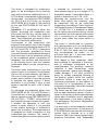
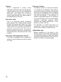
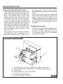
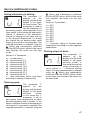
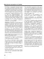
Bear
Operation and
Installation Guide
20, 30, 40, 50 KLZ
Stationary cast iron boiler
Output range 17 – 44.5 kW
Continuous output modulation
Integrated 110 l hot water tank
www.protherm.eu
Protherm spol. s r.o.
Pplk. Pľjušťa 45
909 01 Skalica, Slovakia
Tel.: +421 34 6966 101
Fax: +421 34 6966 111
Your service organisation:
EN
version
xxxx_01 - v.3 2/2007
Bear 20 (30, 40, 50) KLZ
The boiler’s Serial no. is shown on the plate which is attached to the rear side of the control
panel. The control panel is accessible after removing the front cover.
In the section “Operating Instructions” you will find description of the boiler’s main functions
and guidelines on how to handle the boiler safely. The section “Installation Instructions”
is for skilled workers only.
Obsah
Table of contents
Introduction ........................................... 2
OPERATING INSTRUCTIONS
INSTALLATION INSTRUCTIONS
Controls and signals ............................. 4
Introduction .......................................... 17
Selecting Read mode ........................... 5
Delivery completeness ........................ 20
Selecting Setup mode .......................... 5
Preparing for boiler installation ............ 21
Schematic diagram of boiler control ..... 7
Installing the boiler............................... 23
Error codes ........................................... 8
Operating the boiler ............................. 25
Starting up and shutting down boiler .... 9
Service modes..................................... 27
Boiler control......................................... 9
Electrical connection of boiler .............. 28
Protection functions ............................. 10
Converting to different fuel .................. 29
Service and maintenance .................... 11
Electrical wiring diagram..................... 31
Warranty and warranty conditions ....... 12
Technical specifications ....................... 13
Connection dimensions ....................... 15
Schematic diagram of boiler ................ 16
1
Introduction
1. The boiler and all the associated
equipment must be installed and used in
accordance with the installation design,
all the corresponding valid legal
prescriptions and technical norms and
with the manufacturer’s instructions.
2. The boiler may be installed only in an
environment for which it is designed.
3. After installation, the boiler may be put
into operation by an authorised service
organisation only.
4. The boiler complies with the prescriptions
valid in the Slovak Republic. When used
in the conditions of other countries, any
applicable deviations must be identified
and addressed.
5. In the event of a defect call the
manufacturer’s service organisation –
any unauthorised intervention may
damage the boiler (and possibly also
associated equipment!).
6. The service technician putting the boiler
into operation for the first time is obliged
to familiarise the user with the safety
elements of the boiler, their characteristics
and with the relevant required response
of the user, with the fundamental parts of
the boiler and manner of use of the
boiler. If this technician is also delivering
the boiler, he/she must ensure that the
original packaging of the boiler is
available for potential further transport
thereof until the moment of launch into
operation.
7. Check whether the delivery is complete.
8. Check whether the model and type
supplied corresponds to the type required
for use, i.e. check whether the data
relating the boiler settings stated on the
plate correspond with the data relating to
the local network supplying fuel (gas) to
the place of installation, or have this
performed by a professional technician
who shall install the boiler or put it into
2
operation.
9. Whenever you are not sufficiently certain
of how to control the boiler, seek out and
study all the corresponding instructions
in this Operation and Installation Guide
carefully and proceed accordingly.
10.Never remove or damage any markings
and signs on the boiler. Also store the
original packaging of the boiler in an
undamaged condition for potential
further transport in the case that the
boiler is not put into operation.
11. . . . When performing any repairs, only
original parts may be used. It is prohibited
to make any changes to the boiler’s
internal installation, or to interfere with
this in any way.
12. . . When shutting the boiler down for a
longer period of time, we recommend
that you close the gas supply and
disconnect the boiler from the electricity
network. This recommendation applies
in conjunction with the general conditions
stipulated in this Operation and
Installation Guide.
13.At the end of its useful life, the boiler or
its parts must be disposed of ecologically,
in a manner which avoids causing any
harm to the environment.
14. . The manufacturer is not liable for and
provides no warranty for damages
caused by the failure to abide by:
• the conditions stipulated in this Operation
and Installation Guide;
• prescriptions and norms;
• proper installation and operation
procedures;
• conditions stated in the Warranty
Certificate and the Service Book.
15. .If the boiler is delivered to the user by
the technician who also installs the
boiler, this technician is also obliged to
present to the user all the accompanying
documentation for the boiler (in particular
the Operation guide, Service Book etc.).
If the boiler is not put into operation, the
original packaging of the boiler must be
available for the potential further
transport thereof.
Safety of equipment and people
• According to the findings of the SZÚ
Brno (National Testing Institute), the
boiler (as well as all its optional
accessories)
complies
with
the
requirements of European Directive
90/396/EEC on gas-fuelled appliances
and European Directive 92/42/EEC on
efficiency, the European Directive
2006/95/EC on electrical means of
operation for use in certain voltage
ranges and the European Directive
89/336/EEC
on
electromagnetic
compatibility.
• The appliance is also approved according
to the European norms EN 677, EN 625,
EN 60335-01, EN 50165, EN 55014, EN
61000-3-2 and EN 61000-3-3.
• In order to operate and handle the boiler
in accordance with the purpose for which
it is designed in actual conditions of use
(hereafter referred to only as use), it is
necessary to abide also by additional
conditions – the most essential of which
(i.e. those which must not be omitted)
are found in the following regulatory
documents:
- in the design area: STN 06 0310 and
STN 06 0830;
- in the fire safety area: STN 92 0300;
- for installation and fitting (and repairs):
STN EN 1755 or STN 38 6460, as
applicable STN 38 6462, Decree no.
48/1982 Coll. (as amended by the later
prescriptions)
and
the
binding
occupational health regulations;
- in time of running and operation: STN 38
6405.
- in the area of discharge of combustion
gases and air inflow STN EN 483,
company material – “catalogue of dual
piping for discharge of combustion gases
and inflow of combustion air designated
for type C gas appliances, i.e. in closed
“TURBO” version
• In addition to the above mentioned
documents, it is necessary when using
the boiler to proceed in accordance with
this Operation and Installation Guide
and
the
accompanying
boiler
manufacturer’s documentation. During
use of the boiler any handling by children,
persons under the influence of
intoxicating substances, non-certified
persons, etc. must be prevented.
In practice situations may arise in which
the following essential measures must be
adopted:
• prevent the boiler from (even accidentally)
being switched on while conducting
inspections or working on the combustion
gases flue route or gas and water
distribution pipes by disconnecting the
boiler from electrical power supply also
by other means than only using the main
switch (e.g. by pulling the power cord
plug out of the power socket);
• shut the boiler down every time when
there are any (even temporary)
flammable or explosive fumes present in
the area from which combustion air is
supplied to the boiler (e.g. from paint
when painting, laying and spraying
molten substances, from gas leaks,
etc.);
• if it is necessary to drain water from the
boiler or from the whole system, the
water must not be dangerously hot;
• in the case of a water leak from the
boiler’s heat exchanger or when the
exchanger is clogged up with ice, do not
attempt to start up the boiler until normal
operating
conditions
have
been
restored;
• when a gas leak has been detected or
the gas supply has failed, or in the case
of suspicion that this has occurred, shut
the boiler down, turn the gas supply off
and call the gas board or a service
organisation.
*e.g. TPG 800 01
3
Operating instructions
Controls and signals
3
6
7
1
2
4
5
Fig. 1
Main switch
The main switch (Fig. 1, Position 7) is
used to switch the boiler on or off. The
main switch is situated on the right side of
the boiler control panel.
Caution: The boiler must be put into
operation and switched on for the first time
by an authorised service organisation!
Control panel
On the boiler’s control panel you can
monitor current values and set the required
parameters.
4
The control panel has the following control
elements (Fig.1):
1 Timer switch – sets attenuation of tank
heating and attenuation of heating water.
2 MODE button – transition into setting
mode.
3 Display panel.
4
button.
5 Pressure gauge – displays pressure of
heating water.
6 RESET button – to unblock errors.
7 Main switch – switches boiler on and
off.
Selecting Read mode
Displaying heating water
temperature
After turning the
boiler on by pressing
the main switch, the
current temperature
of the hot water
will appear on the
display.
Displaying hot water temperature
After
pressing
the
button, the
temperature of the
heating water in the
tank will appear on
the display. In this
display the diode is lit in the upper lefthand corner, which indicates the value of
the current hot water temperature in the
tank. If the parameter “--“ appears on the
display instead of a numerical value this
means that the boiler is not in priority hot
water heating mode but is only warming
the heating water into the system.
Note: Switch between the display of the
current temperature of the heating water
and the temperature of the hot water in
button.
the tank using the
Other values on display
Without regard to displaying the
temperature of the hot water and
temperature on the heating water, one
of the following statuses is signalised by
means of the diode in the lower right-hand
corner:
• diode not lit – no requirement for
burning
• diode flashing – requirement for burning
from tank (requirement for additional
heating of hot water in tank)
• diode lit – requirement for burning from
room control unit
Displaying heating water pressure
Pressure of heating water in the boiler
is displayed constantly on the analogue
pressure gauge (fig 1, position 5).
Selecting Setup mode
Setting hot water temperature
Press the MODE
button – the diode in
the upper left-hand
corner of the display
flashes and the diode
in the lower right-hand
corner is lit. Use the
button to set the required temperature
of hot water in the tank. The setting range
of hot water values is --, 40, 44, 48, 52, 56,
60, 64, 68, 70˚C. On setting the parameter
-- the boiler warms only the heating water
into the heating system. By pressing the
MODE button the selected value is saved
into the memory and the mode for setting
the heating water temperature appears on
the display.
Setting heating water temperature
In the heating water
setting mode, the
diode in the upper
left-hand corner of
the flashes and the
diode in the lower
right-hand corner is not lit. Use the
button to set the required temperature of
heating water into the system. The setting
range of heating water values is --, 45, 50,
55, 60, 65, 70, 75, 80, 85˚C. On setting
the parameter -- the boiler warms only the
hot water in the tank – the boiler works in
“summer mode”. By pressing the MODE
button the selected value is saved into the
memory.
5
Equithermal mode
Curve slope
Setting the equithermal mode, i.e.
selection of the equithermal curve slope
and parallel shift of the curve, is possible
only in the case that an outdoor sensor is
attached to the boiler.
Note: If no outdoor sensor is attached, the
boiler will not enable the user to transfer to
setting mode E and P.
Setting curve slope
Press the MODE
button
until
the
parameter E appears
on the display. At
the same time the
diode in the upper
left-hand corner flashes. Using the
button set the required curve E1 – E9
and subsequently confirm selection by
pressing the MODE button. In the case of
selecting the parameter E- the equithermal
mode is switched off. The required output
temperature of the heating water from the
boiler has a value according to the outside
temperature and the relevant set curve
(Fig. 2).
Fig. 2
Parallel curve shift
Parallel curve shift
Press the MODE
button
until
the
parameter P appears
on the display. At the
same time the diode
in the upper left-hand
corner flashes. Using the
button set the
required curve P1 – P9 and subsequently
confirm selection by pressing the MODE
button.
Value shift of individual curves:
P1 - posun o -15 °C
P2 - posun o -9 °C
P3 - posun o -6 °C
P4 - posun o -3 °C
P5 - posun o +3 °C
P6 - posun o +6 °C
P7 - posun o +9 °C
P8 - posun o +15 °C
P9 - posun o +21 °C
P− - no shift
6
Fig. 3
The required temperature of the heating
water according to the curve set in advance
is reduced (P1 to P4) or increased (P5 to
P9) by the set value, or remains without
shift (P-).
Schematic diagram of boiler control
Valid only for connection of outdoor sensor
Fig. 4
7
Timer switch
The timer switch serves for setting
attenuation of heating the hot water in
the tank, i.e. during the interval of the set
attenuation the boiler does not heat the
water in the hot water tank to maintain
temperature. The length of the attenuation
interval is set by the cogs on the perimeter
of the clock rotor. The interval is set to
where the cogs face outwards – see
diagram. There may be more than one
interval, i.e. there may be a number of
attenuations per day.
Error codes
No flame – F1
This signals automatic
irreversible blocking of
the automatic ignition
and closure of the
gas valve, i.e. LOSS
OF FLAME. This
blocking occurs always in the mode when
the gas valve is open and no feedback
signal about the presence of the flame is
sent. The boiler is switched off and cannot
be started.
This fault however may be caused by
intervention with the safety elements
– emergency thermostat and combustion
gas thermostat.
Press the RESET button (fig. 1, position 6)
to unblock the fault. If the fault persists call
an authorised service.
Sensor error – F2
This signals a fault
of the heating water
sensor or a drop in
temperature of the
heating water below
3°C. The boiler is
switched off and cannot be started. Call
an authorised service.
8
Boiler overheated – F3
This signals a heating
water
temperature
higher than 95°C. The
boiler is shut down
and restarts itself
automatically
after
the water has cooled.
Sensor error – F4
This signals a fault of
the hot water sensor.
Heating of the hot
water tank is blocked,
whilst
the
mode
of heating into the
system is not affected by this fault.
Outdoor sensor error – F5
This signals a fault
of
the
outdoor
temperature sensor
when
equithermal
boiler
regulation
is set. The boiler
continues unlimited in its activity, but the
heating water temperature is regulated
according to the value set on the boiler
(see “Setting heating water temperature”,
page 5).
If the boiler is not in equithermal regulation
mode this fault does not occur.
Starting up and shutting down boiler
Starting up the boiler
Important: Putting the boiler into operation
and starting it up for the first time must be
performed by an authorised service only!
If you wish to start the boiler up after it has
been put into operation, make sure that:
1 the boiler is connected to the electrical
power supply;
2 all stop valves (heating water, hot water,
gas) underneath the boiler are opened;
3 the heating water pressure is lower than
indicated on the pressure gauge – red
adjustable hand (water in boiler must be
cold).
Turn the main switch (Fig. 1, position 7)
to the ON position (I). The boiler is ignited
and heats the hot water in the tank. After
this has been heated, the boiler heats the
water in the heating system – if the heating
water temperature is set and a command
for heating is sent from the regulator.
In the event of a safety boiler shutdown an
error code appears on the control panel
(see “Error codes”, page 8).
Unblock the boiler by pressing the RESET
button (fig 1, position 6). If the emergency
shutdown recurs after a short time again,
or if the boiler cannot be unblocked by
pressing the RESET button, call an
authorised service organisation.
Shutting the boiler down
The boiler can be shut down for shorter
periods by switching off the main switch.
If the boiler is to remain shut down for a
longer period of time, also remove the
flexible power cord plug from the socket
and close the gas inlet to the boiler. If
there is no danger of the boiler freezing,
water can be left in the boiler, in the
opposite case it is necessary to discharge
the water from the boiler and from the
system. If the arrangement of the heating
system enables this, upon disassembly of
the boiler discharge water only from the
boiler and leave water in the system so as
to avert danger of corrosion.
Boiler control
Using the boiler without a room
control unit
When running in this mode, the boiler
maintains the selected heating water
temperature. No room control unit is
connected, the terminals for its connection
must be mutually interconnected (standard
factory setting).
Setting procedure:
• turn the main switch to the ON position;
• set the required heating water
temperature on the control panel.
Using the boiler with a room control
unit
The boiler maintains the selected
heating water temperature. Switching
of the terminals to the room control unit
connection is cancelled and the room
control unit is connected. The boiler is
switched on and off according to the
internal temperature of the room in which
the room control unit is installed. This
room must not have thermostatic valves
installed on heating radiators.
Important: On the control panel it is
necessary to set the heating water
temperature (temperature of the water
in the system), which will be capable of
covering thermal losses of the building
even at low outdoor temperatures.
Note: Use control units recommended and
supplied by the PROTHERM company,
which are designated and tested for the
given type of boiler. In the case of use of
other regulators we do not guarantee the
correct and full functioning of the boiler.
9
Operation of boiler with equithermal
control
The boiler regulates the heating water
temperature on the basis of outdoor
temperature changes. In the case of this
type of regulation it is necessary to set
the equithermal curve according to the
required heating water temperature. It
is also necessary to attach an outdoor
temperature sensor. The procedure for
setting equithermal curves is outlined on
page 6 of this manual.
Important: The room control unit and
outdoor temperature sensor must be
connected only by an authorised service.
Note: During all types of boiler regulation,
heating of the hot water in the tank always
has priority, i.e. when a command for
heating the hot water is sent from the
tank, the boiler automatically switches
to the mode of heating the hot water in
the tank. After heating the hot water to
the required temperature the boiler is
automatically switched to the regime of
heating the heating water into the system
and continues in the heating system.
Setting boiler output
The factory setting of the boiler is to
maximum output. In case of necessity it is
possible to adjust the output of the boiler
according to requirement (with regard to
the properties of the boiler). In the case of
heating the hot water in the tank up to the
required temperature the boiler always
works at full output.
Important: Change of setting of boiler
output must be performed only by an
authorised technician.
Protection functions
Continuous output modulation
This takes place on the basis of constant
comparison of the actually attained
values with the values requested (set) by
the user; this regulation is proportional,
i.e. in the case of a larger difference of
compared values the boiler works with a
higher output and vice versa.
Protection against freezing
When the temperature of the heating water
drops below 8°C, the boiler is automatically
started and heats the heating water.
Protection of hot water tank against
freezing
When the hot water in the tank drops
below 8°C, the boiler is automatically
started and heats the tank. This function
is active only in the case that heating of
the hot water in the tank is switched off.
Pump protection
There is a possibility of blockage of the
pump due to sedimentation of sludge in
its bearings when the pump is idle for a
10
longer period of time. Switch the pump on
for a short time when it has been in the
room continuously for 24 hours.
Running down of pump
After the boiler is switched off by the room
control unit the pump continues to ensure
circulation of water in the heating system
for approximately 1 minute (only in heating
mode).
Anti-cycling
After the boiler has been shut down in
heating mode it cannot be restarted
sooner than 1 minute after shutdown
and the temperature of the heating water
drops by 8°C.
Note: This does not apply when the boiler
has been switched off by the room control
unit.
Protection against overheating
The pump is switched on always when
the temperature of the heating water is
higher than was set by the user, or if the
temperature of the heating water is higher
than 85°C. The boiler is switched off when
the temperature of the heating water is
higher than 90°C (fault F3).
Running pump depending on
heating water temperature
The boiler enables setting running of the
pump after a certain selected temperature
has been reached. This function can be set
only by an authorised service technician.
Chimney draught control system
The boiler is equipped with a “Chimney
draught control system” (CDCS). Upon
an accumulation of combustion gases in
the boiler, i.e. in the case of insufficient
discharge of combustion gases, the CDCS
is activated and the boiler switched off
(inflow of gas into the boiler is shut off).
Power failure
Power failure will turn the boiler off. When
power supply is restored, the boiler will
automatically restart itself without losing
any of the operating parameters settings.
If an error code appears on the display
after electrical power supply restoration,
unblock the boiler using the RESET
button.
Note: The boiler may be blocked as a
consequence of overheating caused by
the pump being switched off as a result of
power failure. Rectify this fault by pressing
the RESET button on the boiler control
panel. If the fault persist call an authorised
service.
Safety valve
The boiler is equipped with a safety valve
with an opening pressure of 3 bar. DO NOT
TOUCH THE SAFETY VALVE! Whenever
the safety valve starts releasing heating
water, switch off the boiler, disconnect if
from the electrical power supply and call a
service organisation. If the heating system
repeatedly loses pressure, consult your
service organisation.
Important: All the mentioned electronic
protection functions are enabled only
when the boiler is connected to power
supply (the power cord plug is inserted
into a power socket and the main switch is
in the ON position (I).
Service and maintenance
Maintenance of boiler by user
According to requirement the boiler casing
is cleaned without removing the upper
cover. Cleaning is performed when the
boiler is disconnected from the electrical
power supply by switching off the mains
switch and removing the power cord plug
from the socket. If the surface of the boiler
is damp it can be switched back on only
after it has dried.
It is necessary to check the water pressure
in the heating systems once in a while and
if necessary top up the water. Water can
be added into the heating system after
the boiler has cooled to less than 40°C
(measured by the thermometer on the
boiler). Failure to abide by this condition
may result in leakage or cracks caused by
stress in the block of the boiler.
In the case of gas leakage it is necessary
to shut down the boiler, close the gas
valve and call a service organisation.
Protection against legionella
It is recommended to that the hot water
in the tank is either heated constantly
to a temperature of 65°C or that the
temperature of heating the hot water is
increased at regular intervals to 70°C
in order to eliminate the possibility of
the spread of Legionella pneumophila
bacteria or other types of bacteria.
11
Professional maintenance of boiler
Once per year, preferably before the
beginning of the heating season, we
recommend that the boiler is checked and
set by a service organisation. This check
is not covered by the boiler’s warranty.
The specific tasks to be performed are
specified in the Service Book.
This mostly concerns tasks such as
checking the function and state of the
burner, checking and setting output,
checking the tightness of connections
of the flue conduit, checking the boiler
exchanger, checking the hot water tank
and checking the state of the magnesium
electrode.
In this it is particularly important to verify
the functional capability of the safety valve
and also verify the activity of the emergency
and combustion exhaust thermostat. This
check is performed upon every service
intervention on these elements.
We recommend that the state of the
magnesium electrode is checked within six
months of putting the boiler into operation.
Deterioration of the electrode depends
on the composition and hardness of the
water. Longer time intervals for checking
are stipulated by a professional service
according to the degree of deterioration
following the first check. If 60% of the
electrode has been used up and the time
interval is to remain same, the electrode
Warranty and warranty conditions
The PROTHERM Bear 20 (30, 40, 50)
KLZ is covered by the warranty defined
in the Warranty Certificate, the Service
Book and by other conditions specified
in this Operation Guide and Installation
Guide (chapters Introduction and Boiler
installation).
12
must be replaced with a new one. The
tank must not be operated with a depleted
electrode. The overall warranty of the
boiler does not cover defects caused
by corrosion in the case of a depleted
magnesium electrode.
Note: The depletion of the magnesium
electrode rod ensues from its protective
function, and for this reason replacement
thereof cannot be included within the
warranty.
Technical specifications 20 (30) KLZ
Bear 20 KLZ
Category . . . . . . . . . . . . . . . . . . . . . . . . . . . . . . . . . . . . . . . . . . . . . . . II2H3P
Bear 30 KLZ
Version . . . . . . . . . . . . . . . . . . . . . . . . . . . . . . . . . . . . . . . . . . . . B11BS
Ignition . . . . . . . . . . . . . . . . . . . . . . . . . . . . . . . . . . . . . . . . . . . . . .electronic
Fuel . . . . . . . . . . . . . . . . . . . . . . . . . . . . . . . . . . . . . . .G20 / G31 . . . . . . . . . . . .G20 / G31
Max. thermal input. . . . . . . . . . . . . . . . . [kW] . . . . . . . . 19 / 18 . . . . . . . . . . . . . . 28 / 27
Min. thermal input . . . . . . . . . . . . . . . . . [kW] . . . . . . . 13,5 / 12 . . . . . . . . . . . . . . 20 / 19
Max. thermal output . . . . . . . . . . . . . . . [kW] . . . . . . . . 17 / 16 . . . . . . . . . . . . . 26 / 24,5
Min. thermal output . . . . . . . . . . . . . . . . [kW] . . . . . . . . 12 / 11 . . . . . . . . . . . . . . 18 / 17
Efficiency. . . . . . . . . . . . . . . . . . . . . . . . . [%] . . . . 90 - 92 / 89 - 91 . . . . . . . 90 - 92 / 89 - 91
Gas pressure
Supply pressure . . . . . . . . . . . . . . . . [mbar]. . . . . . . . .18 / 30 . . . . . . . . . . . . . . 18 / 30
Jet diameter . . . . . . . . . . . . . . . . . . . . [mm]. . . . . . . .2,65 / 1,7 . . . . . . . . . . . . 2,65 / 1,7
Gas consumption
(Q max.) . . . . . . . . . . . . . . . . . . . . . . . . . . . . . . .2,0 [m3/h] / 1,6 [kg/h] . . . 3,0 [m3/h] / 2,0 [kg/h]
Heating
Max. operating pressure . . . . . . . . . . . . [bar]
Min. operating pressure . . . . . . . . . . . . [bar]
Recommended operating pressure . . . . [bar]
Temperature range . . . . . . . . . . . . . . . . [°C]
Water volume in boiler . . . . . . . . . . . . . . . [l]
Expansion vessel . . . . . . . . . . . . . . . . . . . [l]
Max. pressure in expansion vessel . . . . [bar]
. . . . . . . . . . . . . . . . . . . . .3
. . . . . . . . . . . . . . . . . . . . .1
...................1–2
. . . . . . . . . . . . . . . . . . 45 – 85
. . . . . . . . . .9,1 . . . . . . . . . . . . . . . . .11,6
. . . . . . . . . . . . . . . . . . . . 10
. . . . . . . . . . . . . . . . . . . . 3,5
Hot water
Max. supply pressure . . . . . . . . . . . . . . [bar] . . . . . . . . . . . . . . . . . . . . .6
Adjustable temperature range . . . . . . . [°C] . . . . . . . . . . . . . . . . . . 40 – 70
Hot water tank capacity . . . . . . . . . . . . . . [l] . . . . . . . . . . . . . . . . . . . .110
Hot water flow (Di according to STN EN 625)[l/min] . . . . . . . . 12,4 . . . . . . . . . . . . . . . . .14,0
Electrical data
Voltage . . . . . . . . . . . . . . . . . . . . . . . [V/Hz] . . . . . . . . . . . . . . . . . . 230/50
Input (max.) . . . . . . . . . . . . . . . . . . . . . . .[W] . . . . . . . . . . . . . . . . . . . .130
Prot. cover . . . . . . . . . . . . . . . . . . . . . . . . . . . . . . . . . . . . . . . . . . . . . . IP 40
Current . . . . . . . . . . . . . . . . . . . . . . . . . . [A] . . . . . . . . . . . . . . . . . . . . 0,5
Exhaust of combustion gases - method . . . . . . . . . . . . . . . . . . . into chimney
Flue diameter . . . . . . . . . . . . . . . . . . . [mm] . . . . . . . . . 130 . . . . . . . . . . . . . . . . 130
Combustion gas temperature . . . . . . . . [°C] . . . . . . . . . . 88 . . . . . . . . . . . . . . . . . 116
Combustion flow mass . . . . . . . . . . . . . [g/s] . . . . . . . . . 13,3 . . . . . . . . . . . . . . . . 19,8
Min. required stable chimney thrust . . . [Pa] . . . . . . . . . . . . . . . . . . . . .2
Noise level (1 m from the boiler at height of 1.5 m)[dB] . . . . . . . . . . . . . . . . up to 55
Dimensions – height / width / depth . . [mm]. . . . . . . . . . . . . . . 1385 / 505 / 892
Weight without water . . . . . . . . . . . . . . . [kg] . . . . . . . . . 145 . . . . . . . . . . . . . . . . . 160
13
Technical specifications 40 (50) KLZ
Bear 40 KLZ
Category . . . . . . . . . . . . . . . . . . . . . . . . . . . . . . . . . . . . . . . . . . . . . . . II2H3P
Bear 50 KLZ
Version . . . . . . . . . . . . . . . . . . . . . . . . . . . . . . . . . . . . . . . . . . . . B11BS
Ignition . . . . . . . . . . . . . . . . . . . . . . . . . . . . . . . . . . . . . . . . . . . . . .electronic
Fuel . . . . . . . . . . . . . . . . . . . . . . . . . . . . . . . . . . . . . . .G20 / G31 . . . . . . . . . . . .G20 / G31
Max. thermal input. . . . . . . . . . . . . . . . . [kW] . . . . . . .38,5 / 36,5 . . . . . . . . . . . . 49 / 47,5
Min. thermal input . . . . . . . . . . . . . . . . . [kW] . . . . . . . 27 / 25,5 . . . . . . . . . . . . . 36 / 32,8
Max. thermal output . . . . . . . . . . . . . . . [kW] . . . . . . . . 35 / 33 . . . . . . . . . . . . . 44 / 41,2
Min. thermal output . . . . . . . . . . . . . . . . [kW] . . . . . . . 24,5 / 23 . . . . . . . . . . . . . 31,5 / 28
Efficiency. . . . . . . . . . . . . . . . . . . . . . . . . [%] . . . . 90 - 92 / 89 - 91 . . . . . . . 90 - 92 / 89 - 91
Gas pressure
Supply pressure . . . . . . . . . . . . . . . . [mbar]. . . . . . . . .18 / 30 . . . . . . . . . . . . . . 20 / 30
Jet diameter . . . . . . . . . . . . . . . . . . . . [mm]. . . . . . . .2,65 / 1,7 . . . . . . . . . . . . 2,65 / 1,7
Gas consumption
(Q max.) . . . . . . . . . . . . . . . . . . . . . . . . . . . . . . .4,1 [m3/h] / 3,3 [kg/h] . . . 5,2 [m3/h] / 3,8 [kg/h]
Heating
Max. operating pressure . . . . . . . . . . . . [bar]
Min. operating pressure . . . . . . . . . . . . [bar]
Recommended operating pressure . . . . [bar]
Temperature range . . . . . . . . . . . . . . . . [°C]
Water volume in boiler . . . . . . . . . . . . . . . [l]
Expansion vessel . . . . . . . . . . . . . . . . . . . [l]
Max. pressure in expansion vessel . . . . [bar]
. . . . . . . . . . . . . . . . . . . . .3
. . . . . . . . . . . . . . . . . . . . .1
...................1–2
. . . . . . . . . . . . . . . . . . 45 – 85
. . . . . . . . . 14,1 . . . . . . . . . . . . . . . . . 16
. . . . . . . . . . . . . . . . . . . . 10
. . . . . . . . . . . . . . . . . . . . 3,5
Hot water
Max. supply pressure . . . . . . . . . . . . . . [bar] . . . . . . . . . . . . . . . . . . . . .6
Adjustable temperature range . . . . . . . [°C] . . . . . . . . . . . . . . . . . . 40 – 70
Hot water tank capacity . . . . . . . . . . . . . . [l] . . . . . . . . . . . . . . . . . . . .110
Hot water flow (Di according to STN EN 625)[l/min] . . . . . . . . 15,3 . . . . . . . . . . . . . . . . . 21
Electrical data
Voltage . . . . . . . . . . . . . . . . . . . . . . . [V/Hz] . . . . . . . . . . . . . . . . . . 230/50
Input (max.) . . . . . . . . . . . . . . . . . . . . . . .[W] . . . . . . . . . . . . . . . . . . . .130
Prot. cover . . . . . . . . . . . . . . . . . . . . . . . . . . . . . . . . . . . . . . . . . . . . . . IP 40
Current . . . . . . . . . . . . . . . . . . . . . . . . . . [A] . . . . . . . . . . . . . . . . . . . . 0,5
Exhaust of combustion gases - method . . . . . . . . . . . . . . . . . . . into chimney
Flue diameter . . . . . . . . . . . . . . . . . . . [mm] . . . . . . . . . 150 . . . . . . . . . . . . . . . . 180
Combustion gas temperature . . . . . . . . [°C] . . . . . . . . . 131 . . . . . . . . . . . . . . . . 115
Combustion flow mass . . . . . . . . . . . . . [g/s] . . . . . . . . . . 31 . . . . . . . . . . . . . . . . . . 50
Min. required stable chimney thrust . . . [Pa] . . . . . . . . . . . . . . . . . . . . .2
Noise level (1 m from the boiler at height of 1.5 m)[dB] . . . . . . . . . . . . . . . . up to 55
Dimensions – height / width / depth . . [mm] . . . . 1385 / 505 / 892 . . . . . . . 1385 / 590 / 892
Weight without water . . . . . . . . . . . . . . . [kg] . . . . . . . . . 185 . . . . . . . . . . . . . . . . . 210
14
Connection dimensions of boiler 20 (30, 40, 50)KLZ
730
e
ød
505
177,5
130
30 KLZ
285
106
505
220
130
40 KLZ
242,5
21
505
262,5
150
50 KLZ
285
21
590
305
180
792
c
191
607
b
327,5
460
a
20 KLZ
120
290
TYPE
976
153
869
892
c
e
50
1385
a
A – hot water input 3/4”
C – hot water output 3/4”
E – heating water output 1”
B – hot water circulation 3/4”
D – heating water input 1”
F – gas input 3/4”
Fig. 5
15
Schematic diagram of boiler
1. Control panel
10. Backflow valve for HeW circuit
19. Hot water (cold water) inlet
2. “POLO-TURBO” superstructure
11. Backflow valve for HoW circuit
20. Filling and discharge
3. Combustion gas collector
12. Gas inlet
21. Burner plate
4. Automatic bleeding valve
13. Heating water outlet
22. Gas valve with ignition automatic
5. Safety valve
14. Boiler body
23. Hinged frontal cover
6. Pump for HoW heating circuit
15. Heating water inlet
24. Set for installation on HoW inlet
7. Combustion exhaust safety valve
16. Hot water tank
25. Expansion vessel for HoW circuit
8. Pump for HeW circuit
17. Hot water outlet
9. Expansion vessel for HeW circuit
18. Connection of HoW circulation
Fig. 6
16
Installation instructions
Introduction
The PROTHERM Bear 20 (30, 40, 50)
KLZ boiler is compatible with common
types of hot water heating systems and
heating radiators.
Important: The PROTHERM boilers must
be put into operation only by authorised
organisations according to Czech Bureau
of Occupational Safety and Czech Safety
Inspectorate Notice No. 21/1979 (in the
wording of Public Notice No. 554/1990
Coll.).
The boiler must be put into operation
and warranty and post-warranty service
must be performed by the manufacturer’s
contracted service organisation, which
meets the above specified requirements.
The boiler is designed to work in a normal
AA5/AB5 environment according to STN
33 2000-3 and STN 33 2000-5-51 (i.e.
within a temperature range of +5 to +40˚C
and humidity depending on temperature
up to maximum 85%).
The 20 (30, 40, 50) KLZ boiler must not be
installed in zones 0, 1 and 2, i.e. in rooms
with a bath tub, in bathrooms, washing
rooms and showers according to STN 33
2000-7-701 (Fig. 7).
The boilers are designed to run with
heating water compliant with STN 07 7401
(above all this water must not under any
circumstances be acidic, i.e. its pH factor
must be greater than 7 and must have a
minimal carbonate hardness).
The requirements for utility water
properties are defined in STN 83 0616 (for
drinking water STN 75 7111). If the water
has a combined calcium and magnesium
concentration greater than 1.8 mmol/l, it is
useful to implement other “non-chemical”
measures against incrustation (e.g. use of
magnetic water treatment combined with
a desludging device).
In the case of clogging of the system with
dirt from the heating system or incrustation sediments or problems caused by
other clogging (e.g. clogging of the heat
exchanger, pump defects) are not covered
by the boiler’s warranty.
Upon installation and operation of the
boiler it is prohibited in the sense of STN
92 0300 for objects (classified according
to STN 73 0823) to be placed at a distance
of less than:
- 100 mm in the case of materials which
are not easily flammable, flammable with
difficulty or medium flammable;
- 200 mm in the case of easily flammable
materials (e.g. chipboard, polyurethane,
polystyrene, polyethylene, sponge PVC,
synthetic fibres, cellulose materials,
asphalt strip, rubber and others).
Important: The surface temperature of the
upper parts of the boiler (particularly the
side walls and the cover) may exceed the
ambient temperature by up to 50°C.
A minimum manipulation (free) space
maintained around the immediate vicinity
of the boiler must be sufficient for a person
to work on it safely with bare hands and
with common hand tools (we recommend
a minimum distance of 300 mm on all sides
and min. 600 mm in front of the boiler).
Zones
Fig. 7
17
The boiler is designed for combustion
gases to be discharged (via a chimney
inlet) with a minimum stabilised thrust of 2
Pa. The boiler is connected to the chimney
inlet by a flue – for the boilers PROTHERM
20, 30 KLZ with Ø 130 mm, for the type
PROTHERM 40 KLZ with Ø 150 mm and
for the type PROTHERM 50 KLZ with Ø
180 mm.
Important: It is prohibited to place any
objects restricting the combustion gas
flow inside the flue (e.g. various types of
heat exchangers to utilise their residual
heat). The combustion gas exhaust flue is
not part of the boiler accessories.
Construction of the combustion gas
exhaust flue as well as that of the chimney
must comply with the requirements of STN
06 1610 and STN 73 4210. Compliance
with the principles specified by these
norms will prevent undesirable phenomena
from occurring, such as excessive cooling
of the combustion gases, penetration of
dampness into masonry and fluctuations
in the chimney thrust, and thus prevent
undesirable effects on the functioning of
the boiler.
The boiler takes combustion air from the
space in which it is installed. The minimum
size of such a space requires that there is
0.8 cu.m of free space per 1 kW of boiler
output, and in addition it must be possible
to ventilate the space directly. If direct
ventilation is not possible 2 cu.m of free
space is required for each 1 kW of boiler
output.
For discharge of combustion gases from
PROTHERM 20, 30, 40, 50 KLZ boilers it
is possible also to use the supplementary
device “superstructure PROTHERM PT 20
(30, 40) POLO – TURBO”, which ensures
the forced discharge of combustion gases.
It enables the operation of cast iron
boilers in cases where it is not possible
to use regular discharge of combustion
gases into a chimney. The superstructure
is designed for direct connection to the
combustion gas collector. The outlet of
combustion gases from the superstructure
18
is adapted for connection of singleshell exhaust piping up to a length of 10
equivalent metres (1 equivalent metre = 1
metre of even section or 1 90° joint).
Mounting the superstructure onto the
boiler and putting into operation may
be performed only by an authorised
organisation according to Public Notice of
the Slovak Bureau of Occupational Safety
no. 74/1996 Coll. It is essential to abide
by the safety prescriptions during service
interventions into the superstructure when
this is connected to an electrical power
source (even when the mains switch is
off)!
The boiler is constructed for operation
with heating water up to an overpressure
of 400 kPa (4 bars), which compiles with
STN 07 7401 (this water must not under
any circumstances be acidic, i.e. its
pH factor must be > 7 and must have a
minimal carbonate hardness).
With regard to their properties, which
are unsuitable for operation of the boiler,
use of antifreeze compounds is not
recommended. This primarily concerns
reduction of heat transmission, large
scale expansion, ageing and damage to
rubber elements. If no other possibility
exists for reliably preventing freezing of
the heating system within the specific
conditions, failure to meet any of the
functional parameters or any defects of
the boiler as a consequence of use of
antifreeze compounds cannot be covered
by the boiler warranty.
The boiler may be used also in systems
with an open expansion vessel. In such a
case it is necessary to ensure an additional
check upon installation and if applicable
also adjustment of the factory setting of
the emergency thermostat temperature
– see point 3.4.
It is necessary to set the expansion vessel
with regard to the system – in the sense of
STN 06 0830 this ensures that the heating
system itself is secured up to a total
volume of 180 litres of water against quick
pressure fluctuations and undesirable
stress on all its elements during operation.
In cases where the total quantity of heating
water in the closed system exceeds 180 l it
is essential to include a second expansion
vessel in the system. This vessel must
have an identical same construction, i.e. it
must be closed, with a membrane.
The resultant value of the water pressure
in the system when cold is constantly
indicated by the red (adjustable) hand of
the boiler pressure gauge. If the pressure
drops beneath such an indicated value it is
necessary to seek and rectify any leakages
or to de-aerate the system more effectively
(or both). If pressure drops repeatedly and
the entire system is effectively sealed and
properly de-aerated, this most probably
represents a fault in the expansion vessel,
and it is essential to call an authorised
technician to rectify this fault.
Upon filling of the hot water tank it is
necessary to open the inflow and outflow
from the tank and allow the water to flow
out until it is entirely clear and without air
bubbles.
Before final assembly of the boiler it is
necessary to flush the distribution pipes
of the heating system several times with
pressurised water. In older, used systems
this must be performed against the flow
direction of the heating water.
Note: It is recommended to mount a
sludge trap in front of the boiler (i.e. on
the piping with return heating water). The
construction of this trap should enable
emptying at regular intervals without the
necessity of discharging a large volume
of heating water. The sludge trap may be
combined with a filter, a filter with a sieve
alone is not sufficient protection.
In the case of clogging of the boiler with dirt
from the heating system, these problems
or problems caused by other clogging are
not covered by the boiler’s warranty. The
filter and sludge trap must be checked
and cleaned regularly.
The requirements for utility water
properties are defined in STN 83 0616 (for
drinking water STN 75 7111). If the water
has a combined calcium and magnesium
concentration greater than 1.8 mmol/l, it is
useful to implement other “non-chemical”
measures against incrustation (e.g. use of
magnetic or electrostatic field).
The tank must not be exposed to the
effects of:
- higher pressures than the maximum
operational pressure;
- direct effects of fire or temperatures
higher than ordinary working and climatic
conditions
- impact, collision, force on the tank
vessel, shakes and vibrations (with the
exception of manifestations during actual
operation – i.e. circulation of heating
water and filling of utility water).
If the hot water issue points (cocks)
are located very far from the boiler, it
is possible to connect further piping,
creating a circuit with constantly flowing
hot water between the boiler and cocks
(hot water circulation circuit). A hot water
outlet is used for the piping from the boiler
to the cocks, the return piping from the
cocks to the boiler is connected to the
“circulation” outlet. With the introduction of
hot water circulation there is no discharge
of cold water from the cock. The hot water
supply is increased by the volume of the
circulation piping – the length of heating
may be perceptibly increased by this or at
the same time also by inefficient insulation
of the piping of the circulation circuit.
The pump for hot water circulation is not
controlled from the boiler and must meet
the hygiene requirements.
If there are special requirements for
relocation of the boiler (e.g. prevention of
damage to covers, limited passage profile
etc.) it is possible to partially disassemble
the boiler from the assembled state in
which it is delivered.
It is necessary to maintain a sufficient
space around the boiler in order to
ensure that handling of the boiler and
its accompanying equipment during
installation and operation can be
performed safely.
19
Delivery completeness
Content of boiler delivery
Content of delivery
PROTHERM Bear 20 (30, 40, 50) KLZ
boilers are supplied completely assembled
and functionally tested. Associated
armatures (safety valve and backflow
clack valve) are enclosed with the boiler
for equipment for the hot water inlet, as
well as a set of adjustable legs.
The delivery includes (Fig. 8):
1. The boiler
2. Operation and Installation Guide
3. Service Book
4. List of service centres
5. Warranty Certificate
Special delivery
On request the following
accessories can be ordered:
selected
1. Outdoor sensor for equithermal control,
order no. 4180
2. Ventilator superstructure PROTHERM
“POLO-TURBO” for thrust exhaust of
combustion gases.
3. PROTHERM room control unit for
regulation of boiler on the basis of
temperature in referential room.
20
Fig. 8
Preparing for boiler installation
Boiler equipment
The boiler PROTHERM 20 (30, 40, 50)
KLZ comprises the following parts:
- cast iron boiler body with thermal
insulation.
- burner plate including gas path and
starting equipment,
- combustion gas catcher with thrust
breaker,
- hydraulic construction,
- boiler casing with control panel,
- hot water tank.
Cast iron boiler body
This is composed of elements and serves
simultaneously as a combustion chamber
(including combustion gas paths) and a
water space (including water paths). The
elements are lateral (“right” and “left”) and
central (of one type). The connection of
the elements creates the boiler body with
the relevant size (both of the combustion
chamber and the water space). The
assembled boiler body is connected to
a hydraulic construction and insulated
against heat loss and radiation. It is also
fitted with clips for fitting the sensors of
the thermostats and thermometer and
clips on legs serving for connection with
the boiler construction, in which the tank
is placed.
Burner plate
This is fitted with a gas pipe section, its
own burner pipes and a starting device.
According to size (which corresponds to
the size of the boiler body) it holds 2 to
4 burner pipes and the entire gas path.
The gas path is formed by a pipe section
of the gas connector, which ends with an
inlet into the combined gas armature. The
combined gas armature regulates gas
inflow into the boiler depending on the
required and attained operational states
of the system (i.e. of the boiler and heating
system together); the outlet from this is
the section of the gas piping of the burner
plate finished with 2 to 4 jets (one on each
burner pipe).
The burner is started by an electrical
spark. An automatic control device is
used to start and maintain running, which
is connected directly with the combined
gas armature manufactured by the same
company to form a single unit, which
also reduces all requirements for mutual
interconnection.
Combustion gas catcher
This is a plate cover which contains the
CDCS thermostat; it is connected directly
to the thrust breaker and finished beyond
this with the combustion gas collector
of the boiler (for connection of exhaust
flue). The CDCS – chimney draught
control system – is based on monitoring
the temperature of combustion gases on
exhaust from the boiler; in the case of
accumulation of these gases in the boiler
(i.e. insufficient exhaust) it is activated
and switches off the boiler (closes the gas
inlet into the burner). The combustion gas
catcher is fitted with a detachable cleaning
jacket, which is accessible after removal of
the upper part of the boiler casing (upper
cover).
Hydraulic construction
This is a system of piping with a pair of
pumps, backflow clack valves and safety
elements, i.e. with an expansion vessel for
the hot water circuit (with nominal content
of 10 l), a safety valve for the hot water
circuit (with nominal opening pressure of
3 bar) and automatic de-aeration by valve.
The hydraulic construction also includes
end pieces for connection of the boiler.
21
Casing
This is composed of covers, firmly
attached to the back wall and side plates,
a detachable frontal wall and detachable
upper part. The upper part contains a
horizontal control panel, and a vertical
control panel beneath the upper edge of
the detachable frontal wall.
Hot water tank
This is a cylindrical vessel containing
spiral piping. The heating water passes
through the piping and heats the utility
water in the vessel. The tank is enamelled
inside and has a magnesium electrode for
protection against corrosion. The external
thermal casing of the tank is composed of
polystyrene foam, with reflexive foil on the
surface.
Hot water tank expansion vessel
The boiler is equipped with an expansion
vessel for the hot water tank with a volume
of 4 litres.
22
Placing of boiler
The boiler is fitted on a construction base,
i.e. a platform (or pedestal). The platform
must have at least a regular load capacity
and must not be slippery. The surrounding
area may be cleaned only in a dry manner
(e.g. by vacuuming). If the platform is
made of flammable material it is essential
to furnish the boiler with a non-flammable,
thermally insulating underlay which
overlaps the ground dimensions of the
boiler by at least 100 mm.
For passage of a boiler with case it is
necessary to meet the condition that the
doors have a width of at least 65 cm.
Adjustable legs
Before connection of the boiler to the
heating system install the adjustable legs
onto the boiler clamps for improved stability
and balancing of the boiler. The instruction
guide is included in the packaging.
Installing the boiler
In the case of service interventions into
the boiler it is unconditionally necessary
whenever the boiler is collected to the
electrical power source (even when the
mains switch of the boiler is off) to abide by
the safety prescriptions for operation and
work on electrical equipment (provision of
norm STN 34 3100).
The boiler casing can be disassembled.
The frontal section is secured by spring
clamps in the upper corners of the casing.
The frontal wall can be folded down by
pulling on the upper corner, the upper
side is folded from the back in an upwards
direction after the removal of two screws.
The remaining parts of the casing are
attached with self-drilling screws to the
boiler chassis. The individual parts of the
casing are connected to the electrical
installation of the boiler by protective
conductors.
Exercise especial caution in transport
handling of the boiler, with regard to the
height of the centre of gravity.
The end pieces for connection are on
the rear side of the boiler (see Fig. 5,
Connection dimensions of boiler).
It is necessary to install a backflow
clack valve and safety valve on the hot
water inlet to the boiler. The clack valve
combined in a single armature is supplied
together with the boiler. The valve
compensates for the volume expansion of
the utility water during heating, and is thus
constantly active, and it is recommended
that water escaping from this is drained by
a permanently installed drainage pipe into
the waste water conduit. It is necessary
for the water to have a smooth passage
of drainage, without any possibility of
accumulation of the drained water. In the
case of a higher pressure of the inlet utility
water then 600 kPa (6 bar) it is necessary
to use a reduction valve before inlet into
the boiler.
Before the combined armature (in the flow
direction of the utility water) it is desirable
to install also a stopper, which is not
included in the boiler delivery.
The combined armature is always installed
– however water leakage from the safety
valve in the armature may be resolved
by installing an expansion tank for utility
water. This concerns a “high pressure”
(but not “heating”!) expansion vessel,
which must have a nominal volume of at
least 3 litres and nominal pressure of 600
kPa (6 bar). It must be placed behind the
combined armature (in the flow direction
of the water), either in front of or behind
the vessel, in an appropriate place of the
hot water distribution system.
Important: There must not be any
stoppers or obstacles to the flow of water
through the piping between the tank and
the safety valve (combined armature)
and between the tank and the expansion
vessel for the utility water!
In order to ensure that no water leaks
from the safety valve after installation of
the “high pressure” vessel, the resulting
working pressure of the vessel must be
10 to 30 kPa (0.1 to 0.3 bar) lower than
the opening pressure of the valve!
The boiler pipe connection pieces (primarily
for gas) must not be subjected to any
forces from the pipe system of the heating
system or gas inlet. This requires precise
adherence to the dimensions of the end
pieces of the connection pipes, vertically
as well as in terms of the distance from
the wall and the mutual distance between
the individual inlets and outlets.
During reconstructions, in unfavourable
building dispositions, etc., it is possible
to connect the boiler to the heating
system and gas mains by means of
flexible elements (hoses), but only those
which are designed for this purpose.
Flexible components should be as short
as possible, must be protected against
mechanical and chemical loads and
23
damage, and must be replaced with
new ones before the end of their useful
life or before their reliability to meet their
nominal parameters (as stated by their
manufacturers) is diminished.
Properties of heating system and
filling the heating system
It is necessary to set the temperature of
the emergency thermostat according to
the type of implementation of the heating
system (open or closed). For open systems
the emergency temperature is set to 95°C,
for closed systems 105°C.
Setting of the heating water expansion
vessel (pressure in its gas equalizing
section) begins before filling – it is
necessary to add extra pressure (e.g. by 50
kPa (0.5 bar) above the expected resulting
water pressure in the system. This ensures
that the equalizing volume is as large as
possible and that this will be used as such
in further operation. The system is then
filled and preliminary pressured by cold
water to the required pressure according
to the pressure gauge on the boiler – in
this manner the remaining (water) part of
the expansion vessel is filled and filling
is closed. In this state the overpressure
is gradually relaxed from the equalizing
part; the pressure in this is monitored by
a pneumometer. Relaxing of the pressure
continues as long as the equalizing part
is “harder” than the water part (pressure
on the pneumometer is higher than on the
pressure gauge on the boiler).
Only when both monitored values become
very close, very carefully continue
relaxing the equalizing part so that the
both values become equal and both begin
to drop – this is the watershed where the
sought largest equalizing volume is set
for the given working point. In this phase
of setting the expansion vessel changes
in pressure are imperceptible and it is
necessary to proceed very carefully,
since the water is practically impossible
to pressurise, and even in the case of
reduction of the pressure effect its volume
24
will be practically unchanged. So when
“throw” takes place during relaxation of
the pressure from the equalizing gas part
and the pressure watershed of the sought
working point is exceeded and the water
volume in the system is not changed, the
gas part can be simply re-pressurised
and pressure relaxation in seeking the
pressure watershed can be repeated
more carefully.
The tightness of the valve of the expansion
vessel is not absolutely constant; if the
pressure in the system drops this may be
caused not only by a water leakage, but
also by a reduction of the pressure effect
of the equalizing gas part of the expansion
vessel on the water part – upon topping
up the system pressure by inlet of water
the gas part may then “shrink” in volume,
which reduces the overall expansion
capability of the expansion vessel as
against its nominal state. For this reason
it is never possible to resolve setting
of the expansion vessel only by simple
pressurising of the equalizing gas part
in operation with a longer duration with
absolute certainty (or even in the shortest
operation if water has been charged into
the system)!!!
Setting of the hot water expansion vessel
resides only in its pressurising before filling
utility water into the boiler and distribution
system to the resulting working pressure.
After filling the heating system, de-aeration
and setting the pressure expansion vessel
(if this is used), the resulting pressure of
the heating water in the system when cold
is indicated by the (red) adjustable hand
of the boiler pressure gauge.
Operating the boiler
Preparing and starting the boiler
Check the water pressure on the boiler
pressure gauge. By opening the gas cock
gas is inlet into the boiler. Connect the
plug of the flexible power cord into the
socket and press the mains button. The
heating and hot water are set to approx.
½ of their volume. In the first additional
“mode” we select automatic setting of the
heating water temperature for running of
the pump, for subsequent actual operation
this is adjusted further as applicable. The
boiler ignites and heats the hot water.
After this heating the boiler heats in the
heating system.
During the running of the boiler check the
gas tightness of all connections of the
gas path in the boiler, e.g. using a foam-
forming solution. It is necessary to rectify
any determined leakages and repeat the
check.
At the end of preparing and starting the
boiler check and if necessary adjust the
output of the boiler with regard to the
heating system by setting the gas pressure
on the outlet of the gas armature and set
this according to the requirements of the
customer.
Setting gas pressure
Output is set using the regulating elements
on the combined gas armature (see
illustration of gas armature), pressure
is measured using the U-manometer
(against atmosphere).
Regulating gas armature
A
B
D
∅ 8
2
1
C
1 – measurement point of gas pressure on inflow to armature
2 – measurement point of gas pressure on outflow from armature
A – cover plug
B – setting (internal) screw of maximum
C – setting screw of minimum
D – electrical setting of minimum
Fig. 9
25
Before commencing setting, when the
boiler is switched off (plug of electrical
power cord is removed from socket), it is
necessary to:
- detach the covering (metal) plug (A)
- relax the closing screw of the
measurement point (2) of outflow gas
pressure and slide on the tube of the Umanometer (screw not removed)
Maximum output
- The boiler is put into operation and left to
work during hot water consumption at
maximum output. The course of
measurement should not be interrupted
by switching off the boiler e.g. by reaching
the maximum hot water temperature or
heating water temperature etc.;
- By turning the plastic screw (B) the gas
pressure is set to maximum output – by
turning it clockwise gas pressure is
increased:
• 125 mm of water column for natural gas
• 270 mm of water column for propane
Reduced output
Measurement is performed upon soft start
after the boiler is switched on in heating
mode (this state persists for max. 100
seconds)
- using the screw (C) the left limit position
is set to minimum output (anticlockwise)
- the dial (D) on the automatic device is
used to set:
• 55 mm of water column for natural gas
• 130 mm of water column for propane
After completing setting switch the boiler
off, remove the U-manometer tube and
slightly tighten the closing screw at the
measurement point. Screw the metal
cover plug back on. Put the boiler into
operation and perform a tightness test
of the measurement points on the gas
armature.
26
First heating
The first heating is a short, sharp operation
of the boiler after its initial connection to
the heating system.
Set the boiler control elements (operational
controls, room control unit) so as to
attain the highest possible heating water
temperature in the system and at the
same time the smallest possible number
of shutdowns of the boiler. Maintain the
entire system (boiler and heating system)
in these conditions until it is stabilised
(i.e. the temperature becomes constant
also on the body at the furthest distance
from the boiler), and for at least one hour
more.
The boiler is shut down. Record the
pressure value (on the boiler). Once
more carefully de-aerate the system and
subsequently pressurise to the recorded
value.
Finally the system is allowed to cool.
During the drop in temperature check that
there is not also simultaneously a marked
pressure drop. In the case of such a
pressure drop check for leakages, rectify
them and repeat the first heating.
Service (additional) modes
Setting attenuation in heating
The parameter “u”
appears
on
the
display and the diode
flashes in the upper
left-hand corner. This
parameter is used to
set the attenuation in
the heating system, which depends on the
timer switch. In this setting the attenuation
interval is identical to the attenuation
interval for heating the hot water tank up
to the required temperature, i.e. during
this interval the set heating water value
drops by the value of this parameter. The
required parameter is selected using the
button and subsequently confirmed
with the MODE button, which at the same
time transfers the boiler into the next
mode.
Values of “u” parameter:
u1 – no attenuation
u2 – attenuation by 3°C
u3 – attenuation by 6°C
u4 – attenuation by 9°C
u5 – attenuation by 12°C
u6 – attenuation by 15°C
u7 – attenuation by 18°C
u8 – attenuation by 21°C
u9 – attenuation by 24°C
u- - max. attenuation (boiler shut down
according to setting of timer switch)
button and subsequently confirmed
with the MODE button, which at the same
time transfers the boiler into the next
mode.
Values of “t” parameter:
t1 = 40°C
t2 = 45°C
t3 = 48°C
t4 = 50°C
t5 = 52°C
t6 = 54°C
t7 = 56°C
t8 = 58°C
t9 = 60°C
t– - automatic setting of heating water
temperature according to current required
temperature.
Starting output of boiler
The parameter “n”
appears
on
the
display and the diode
flashes in the upper
left-hand corner. In
this mode the starting
output of the boiler is
set as follows: “n -” – maximum starting
output. The required parameter is selected
using the
button and subsequently
confirmed with the MODE button, which
at the same time transfers the boiler into
the next mode.
Running pump
The parameter “t”
appears
on
the
display and the diode
flashes in the upper
left-hand
corner.
In this mode the “t”
parameter is set to
the heating water temperature at which
the heating water pump is started, i.e. the
pump is switched on when the temperature
set using the “t” parameter is reached. The
required parameter is selected using the
27
Electrical connection of boiler
The boiler is connected to power supply
by a three-core flexible cord with a plug.
A fixed socket through which the boiler is
connected to power mains must comply
with the provisions of STN 33 2000-4-46.
This must always have a protective (earth)
contact (pin), reliably connected by a PE
or PEN wire (yellow-and-green). The
boiler must be always connected to the
protection wire (earth) through its power
cord and must be always installed in such
a manner that the socket and plug are
accessible. Use of adapters, extension
cords etc., is not permitted.
Important: Preparation of the socket and
connection of the room control unit, which
requires intervention with the boiler’s
internal wiring, must be always connected
by a qualified electrician in accordance
with Public Notice No. 50/1978. Likewise
servicing of the electro-technical part
must be performed by only a person with
the above qualification. Before performing
any works on the electro-technical part,
the boiler must be disconnected from the
power supply by removing the power cord
plug from the power socket!
The main part of the boiler is secured by a
tube fuse (T1, 6A / 250 V), which is located
on the control panel of the boiler.
For control of the boiler using a room
control room unit only a zero-potential
output room control unit may be used, i.e.
a unit which convey no foreign voltage to
the boiler.
The room control unit must be connected
to the boiler by a two-core cable. The
recommended copper wire cross-section
is 0.5 to 1.5 sq.mm.
The room control unit connection cables
must not run concurrently with power
wires or cables.
28
The terminal for connection of the room
control units is equipped from the factory
with a jumper and is located in the electrical
box of the boiler. Before connection of the
room regulator it is necessary to remove
the jumper on the terminal. In all other
cases the jumper is left.
If the boiler is to be operated in the
continuous control mode according to
outside temperature, i.e. equithermal
regulation, an outdoor temperature sensor
is attached to it.
This sensor is located outside, preferably
at half the height of the building (or of
the heated zone), at least 2.5 m above
the ground. If equithermal regulation is
predominantly intended to control heating
according to the required comfortable
temperature, the sensor is placed on the
same side of the building as the windows
of the heated rooms – if this cannot be
secured then it is placed on the northwestern side. If equithermal regulation is
predominantly intended to optimise the
quantity of heat, the sensor is always
placed on the coldest (most often north)
side of the building.
The sensor is connected to the boiler by
a two-core cable with a cross-section of
(copper) conductors of at least 0.5 sq.mm
and a length of maximum 30 m (between
boiler and sensor, i.e. total 60 m of
conductor measured from boiler to sensor
and back to boiler). This cable must not run
concurrently with other electrical wiring
and areas with more powerful electrical
machinery (e.g. welding machines).
Diagram of connection of external elements
Terminals for connecting
outdoor sensor
1
2
Room control unit
3
4
5
6
BOILER
Power cable
(without plug)
Select this
connection only if
you want to connect
a room control unit
Connection of external control unit
(not part of delivery)
Main power connection (230V)
Fig. 10
Converting to different fuel
If it is necessary to convert to a different
type of fuel (natural gas to propane and
vice versa), the boiler is reconstructed in
the following manner. This reconstruction
may be performed exclusively by a service
authorised by the manufacturer.
The following are performed:
1. Disassembly of burner from boiler;
2. Replacement of all burner jets with
others (according to type of fuel).
3. Replacement of burner tubes with others
(according to type of fuel).
4. Upon change from natural gas to
propane the cooling rods including
clamps are mounted on the burner tubes
– three rods on each tube. The rod in the
axis of the combined ignition electrode is
shortened by approx. 35 mm. Upon
change from propane to natural gas, the
cooling rods must be removed.
5. Re-mounting of burner.
6. Setting of prescribed gas pressure to
designated boiler output (see chapter
“Preparing and starting the boiler”).
Together with setting the prescribed gas
pressure for the designated boiler output
the following are performed:
- upon change from natural gas to propane
setting of “SOFT-LITE” to MAX (fastest
opening of gas valve);
- upon change from propane to natural
gas setting of “SOFT-LITE” to MIN
(slowest opening of gas valve).
“SOFT-LITE” is located on the foot of
the body, on the side of gas outlet from
the valve. It has a dark plastic plug with
bayonet hook (turning and removal of plug
must be performed without use of force
29
– otherwise this could cause damage
(tearing) of “SOFT-LITE”). The red rotating
knob underneath the plug has an arrow,
which:
- if turned in the direction of gas flow is at
the value MAX;
- if turned against the direction of gas flow
is at the value MIN.
7. Checking of the tightness of connections
of the gas path and subsequent safety
measures:
- the type of fuel for which the boiler is
now designated is indicated on the boiler
in an appropriate manner
- change, date and person performing
change are recorded in the accompanying
technical documentation of the boiler.
Important: In the case of reconstruction
30
only original parts supplied by the
manufacturer or person authorised by the
manufacturer are used. Reconstruction
may be performed only by a qualified
technician! In changing the type of fuel it
is essential to respect the requirements
for construction of the screw connections
on the gas piping inside the boiler, i.e. to
seal them with material appropriate for
assembly and corresponding effects of
the given type of fuel:
- for natural gas e.g. plumbing hemp
infused with varnish, linseed oil etc.;
- for propane-butane e.g. plumbing hemp
infused with spirit cements produced
either from lamp black (type HERMETIC)
or shellac with an admixture of washed
graphite.
The setting of all elements is secured (e.g.
by a drop of paint).
31
Ionising
electrode
Ignition
electrode
Automatic
ignition
S4565 AM
chimney
10V-IP 44
Gas valve Honeywell
red
grey
blue
Heating
circuit pump
black
Yellow/
green
black
blue
Yellow/
green
Yellow/
green
black
blue
black
blue
blue
Main
switch
blue
Tank pump
Reset
button
Emergency
thermostat
Combustion gas
thermostat
Yellow/
green
Chimney valve
(turbo
superstructure)
black
brown
Power cable
Electrical diagram of boiler PROTHERM 20 (30, 40, 50) KLZ
grey
Timer switch
for setting
attenuation
red
Control board
Heating
water sensor
Outdoor
sensor
Room
control unit
Outdoor
sensor
Fig. 11
Hot water
sensor
Control panel