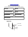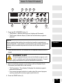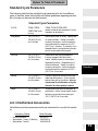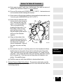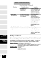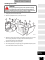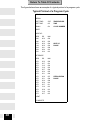
1
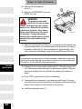
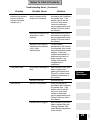
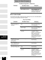
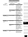
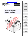
Go To Table Of Contents
Installation
& Operation
Manual
Important
Information
Page 2
Installation
Page 4
Description
M11 UltraClave™
Steam Sterilizer
Page 6
AV SE No
AI RV Lo
LA IC n
BL E P ger
E A in
FO RT P
R S N rod
TH O uc
IS LO tion
PR N :
O GE
D R
U
C
T!
Components
Overview
Page 8
Controls &
Indicators
Page 9
Operation
Page 11
R
RO
ER
R
OR
DO
AJA
Y
DB
AN
/ST
ON
W
R LO
TE
WA
OP
ST
TE
LE
MP
CO
T
AR
ST
G
YIN
DR
ING
S
CK
ILIZ
ER
PA
ST
S
UID
LIQ
G
LIN
FIL
ON
S
DS)
HE
UC
PO
: SEC
P
(°F)
\ TIM
E
(MIN
D
PE
AP
WR
UN
TEM
(PS
I)
RE
SSU
PRE
Operator
Maintenance
Page 20
Calling For
Service
Page 28
®
e
tra
av
Cl
Ul
11
M
Specifications
Page 29
Limited
Warranty
Page 29
Style L
Go To Table Of Contents
Owner’s Product Identification
(information that you will need to provide for servicing - key information is highlighted)
Date of Purchase
Serial Number
Name of Owner / Facility / Department
Model Number
Name of Authorized Dealer
Telephone # of Authorized Dealer
Address of Authorized Dealer
MODEL AND SERIAL
NUMBER LOCATION
MODEL NUMBER
SERIAL NUMBER
MA439101
CONTENTS
IMPORTANT INFORMATION ........................................................................................................ 2
Scope and Purpose of This Manual ...................................................................................... 2
Intended Use of Product........................................................................................................ 2
Safety Instructions................................................................................................................. 2
Explanation of Safety Symbols and Notes ............................................................................ 3
Transportation and Storage Conditions ................................................................................. 3
INSTALLATION.............................................................................................................................. 4
Location Requirements For Sterilizer .................................................................................... 4
Re-Location Requirements For Sterilizer .............................................................................. 5
Electrical Requirements ........................................................................................................ 6
DESCRIPTION............................................................................................................................... 6
Operational Features............................................................................................................. 6
Mechanical Features ............................................................................................................. 7
Safety Features ..................................................................................................................... 7
COMPONENTS OVERVIEW ......................................................................................................... 8
CONTROLS & INDICATORS ........................................................................................................ 9
OPERATION ................................................................................................................................ 11
Recommended Steam Sterilization Monitoring Program .................................................... 12
Sterilizer Preparation Before Operation............................................................................... 12
Cleaning Instruments .......................................................................................................... 13
Guidelines For Loading Trays .............................................................................................. 14
Operation............................................................................................................................. 16
Standard Cycle Parameters ................................................................................................ 19
List of Authorized Accessories ............................................................................................ 19
OPERATOR MAINTENANCE ..................................................................................................... 20
Daily .................................................................................................................................... 20
Weekly................................................................................................................................. 20
Monthly................................................................................................................................ 20
Quarterly ............................................................................................................................. 23
Toubleshooting Guide.......................................................................................................... 24
Error Code Guide ................................................................................................................ 26
CALLING FOR SERVICE ............................................................................................................ 28
SPECIFICATIONS ....................................................................................................................... 29
LIMITED WARRANTY ................................................................................................................. 29
PRINTER INSTALLATION AND OPERATION ............................................................................ 30
Installing the Printer ............................................................................................................ 31
Operating the Printer........................................................................................................... 34
Inserting the Paper Roll....................................................................................................... 34
About the Cartridge Ribbon................................................................................................. 35
Installing a New Cartridge Ribbon....................................................................................... 36
Removing the Paper Roll..................................................................................................... 37
Power Up Message ............................................................................................................. 37
Printer Tape Description ...................................................................................................... 37
Return To Table Of Contents
Important
Information
IMPORTANT INFORMATION
Scope and Purpose of This Manual
This manual provides complete instructions for the installation, operation, and
normal care of the M11 UltraClave™ Steam Sterilizer. It is intended that this
manual be used by all personnel operating the sterilizer or performing operator
level maintenance. No repair information is included in this manual as no repairs are authorized at the operator level.
Intended Use of Product
The M11 Ultraclave is intended to be used in medical and dental offices, hospitals, clinics, nursing homes, laboratories, and other facilities to sterilize heat stable and moisture stable, reusable equipment. Dental handpieces can be
sterilized in the M11 in the Pouches cycle. This device is not recommended for
sterilization of liquids intended for direct patient contact. Refer to Standard Cycle Parameters on page 19 in this manual for detailed information.
Safety Instructions
The primary concern of Midmark is that this equipment is operated and maintained with the safety of the patient and staff in mind. To assure safer and more
reliable operation:
•
•
•
2
Read and understand this manual before attempting to install or operate the
sterilizer.
Assure that appropriate personnel are informed on the contents of this manual; this is the responsibility of the purchaser.
Assure that this manual is located near the sterilizer, or if possible, permanently affixed to the sterilizer.
Return To Table Of Contents
Explanation of Safety Symbols and Notes
DANGER
Important
Information
Indicates an imminently hazardous situation which, if not
avoided, will result in death or serious injury. The DANGER
symbol is limited to the most extreme situations.
WARNING
Indicates a potentially hazardous situation which, if not avoided, could result in death or serious injury.
CAUTION
Indicates a potentially hazardous situation which, if not avoided,
may result in minor or moderate injury. It may also be used to alert
against unsafe practices.
EQUIPMENT ALERT
Indicates an imminently or potentially hazardous situation which, if
not avoided, will or may result in serious, moderate, or minor
equipment damage.
NOTE
Amplifies an operating procedure, practice, or condition.
Transportation and Storage Conditions
EQUIPMENT ALERT
The water must be drained from the unit’s reservoir before transporting or storing at 0°C (32°F) or below. Also, the unit should be
allowed to reach room temperature before operating. Failure to do so could
result in damage to unit.
•
•
•
Ambient Temperature Range: ..... -40°C to +70°C (-40°F to 158°F)
Relative Humidity ........................ 10% to 90% (non-condensing)
Atmospheric Pressure ................ 500hPa to 1060hPa (0.49atm to 1.05atm)
3
Return To Table Of Contents
INSTALLATION
Location Requirements For Sterilizer
Installation
DANGER
Do not operate this sterilizer in areas where flammable anesthetics are used or stored. An explosion could occur, causing personal injury.
Adherence to the following recommendations for location of the sterilizer will
contribute to optimum performance of the unit:
F
E
B
D
C
A
MA439500
Support Surface (A) - Sterilizer must be placed on a level surface to ensure that
the chamber will fill correctly. Improper water level in the chamber could cause
a sterilizer malfunction.
Support Surface Material (B) - Formica, stainless steel, or other water and heat
resistant material. Heat from bottom of sterilizer could reach 71°C (160° F) on
the support surfaces for short periods of time.
4
Return To Table Of Contents
Support Surface Depth (C) - Support surface should be approximately 533 mm
(21 in) deep. Allow at least 51 mm (2 in) clearance behind the sterilizer for air
circulation.
Distance To Side Wall (D) - If the sterilizer is located next to side walls, there
should be no less than 51 mm (2 in) clearance between the side of the sterilizer
and the wall.
Installation
Distance Above Sterilizer (E) - If the sterilizer is to be located beneath wall cabinets or shelves, the underside of the cabinets or shelves should be at least 584
mm (23 in) above the support surface, to provide access to the top inspection
cover and to allow for changing the printer paper roll.
Overhang (F) - If the sterilizer is to be located beneath an overhang, the underside of the overhang should project no further than 381 mm (15 in) over the rear
of the sterilizer.
Location On Support Surface - The front of the sterilizer should be located near
the front of the support surface so water can be easily drained from the tube into
a container.
Neighboring Materials and Equipment - If the sterilizer will be operated in continuous cycles, locate the sterilizer where excessive emission of steam will not
damage materials or equipment in the surrounding area.
Re-Location Requirements For Sterilizer
1. Disconnect power cord from the electrical outlet and allow sterilizer to cool.
2. Drain water from reservoir or take care not to tip the sterilizer, which will
allow water to spill from reservoir.
5
Return To Table Of Contents
Electrical Requirements
WARNING
Installation
Use 220 - 240 VAC, 50/60 HZ alternating current only for 230
VAC models and 90 - 110 VAC, 50/60 HZ alternating current
only for 100 VAC models. Failure to do so could result in electrical
shock to personnel and will result in damage to sterilizer.
Description
Do not use this sterilizer in an explosive or oxygen-enriched atmosphere. Failure to do so could result in serious personal injury or
death.
NOTE
Grounding reliability can only be achieved if this unit is connected to a matching three-pronged, grounded, isolated, correctly polarized receptacle.
The electrical rating for the 230 VAC unit is 230 VAC, 50/60 Hz, 10 amps. The
electrical rating for the 120 VAC unit is 120 VAC, 60 Hz, 15 amps. The electrical
rating for the 100 VAC unit is 100 VAC, 50/60 Hz, 20 amps. The three-pronged
grounding plug on the sterilizer power cord must be plugged into a matching
three-pronged, grounded, isolated, correctly polarized receptacle. Check the
serial number label on the back panel of the sterilizer to verify the voltage rating
for the unit.
DESCRIPTION
Operational Features
The M11 UltraClave™ sterilizers . . .
6
•
will begin a sterilization program cycle when a sterilization program is
selected, the door is closed and fully latched, and the START switch is
pressed.
•
will automatically fill the chamber with water to the correct level once the
START switch is pressed.
•
begin the cycle time countdown only after the proper pressure and temperature have been reached.
•
automatically exhaust the steam pressure from the chamber and open the
door slightly to facilitate drying upon completion of the sterilization phase.
•
automatically starts a 30 minute drying phase. Items that do not require drying may be removed any time after the sterilization phase is complete. Sterility of unwrapped items and moist wrappings is compromised on
exposure to a non-sterile environment.
•
will signal the operator that the drying phase and therefore the sterilization
Return To Table Of Contents
program cycle is complete by sounding five audible “beeps”. The sterilizer
may be switched to standby at this time or restarted if additional sterilization
programs are desired.
Mechanical Features
The M11UltraClave™ sterilizers . . .
•
have a tray rack which can hold two small and two large trays. The tray rack
can be removed for periodic cleaning of the chamber, tray plate, tray rack,
and filter.
•
have an optional printer which provides a permanent record of actual exposure times and temperatures.
•
have a removable power supply cord (100 and 230 VAC units only).
•
have a two gaskets in the door; a dam gasket and a door gasket which can
easily be replaced by operator in seconds.
Installation
Description
Safety Features
The M11UltraClave™ sterilizers . . .
•
have a door stop which prevents the door from opening fully if there is a
slight residual pressure in the chamber when the door handle is operated.
The door stop also retains the door in a partially open position during the
drying cycle.
•
have a door closed switch which is used to signal the sterilizer that the
door is completely closed. This switch is activated just as the door becomes
fully closed. An audible signal will sound and the “Door Ajar” light will flash if
the door is not fully closed.
•
have a water low indicator which signals the operator if there is insufficient
water to fill the chamber to the proper level. An audible signal will sound and
the “Water Low” light will flash if the reservoir needs to be refilled with water.
•
have their chamber temperature monitored during a cycle to prevent an
overheat condition. If chamber temperature reaches or exceeds 146°C
(295°F), power to the sterilizer is cut off.
•
have a pressure relief valve which opens to provide backup protection to
reduce chamber pressure in the event that the chamber steam pressure
exceeds the allowable limit. Released steam is directed out of the bottom of
the unit’s cabinet. An access cover is located on the top cover for relief valve
operational checks.
•
have a fault detection circuit which monitors all functions of the sterilizer
during a cycle. If a fault occurs during a cycle, the sterilizer monitoring circuitry will stop the cycle, sound an audible signal, and light a flashing error
lamp.
7
Return To Table Of Contents
COMPONENTS OVERVIEW
The illustration below shows the location of the sterilizer’s major components
and the chart below provides their descriptive name.
1
8
3
6
2
Components
Overview
5
4
7
MA439900
DESCRIPTION OF COMPONENTS
8
1. Access Cover
5. Door and Dam Gaskets
2. Reservoir Lid
6. Display / Control Pad
3. Printer (Optional)
7. Wire Tray Rack and Tray Plate
4. Level Indicator / Reservoir
Drain Tube
8. Pressure Relief Valve
Return To Table Of Contents
CONTROLS & INDICATORS
The following illustrations show the location of the sterilizer’s controls and indicators and the chart on the following pages describes their function.
3
1
4
5
6
7
8
9
TEMP (°F) \ TIME (MIN : SECONDS)
PRESSURE (PSI)
2
FILLING
STERILIZING
DRYING
COMPLETE
WATER LOW
DOOR AJAR
ERROR
UNWRAPPED
POUCHES
LIQUIDS
PACKS
START
STOP
ON/STANDBY
10
12
11
13
14
15
16
Components
Overview
Controls &
Indicators
17
18
20
19
MA439400
9
Return To Table Of Contents
Controls &
Indicators
Ref.
Control
Function
1
Temperature / Time display
alternately indicates cycle temperature and
exposure time when a cycle is selected. During a cycle, the cycle time remaining is displayed.
2
Pressure display
indicates current chamber pressure during a
cycle.
3
FILLING indicator
illuminates when the chamber is being filled
with water at the beginning of a cycle.
4
STERILIZING indicator
illuminates during the heat up and sterilization
phases of a cycle.
5
DRYING indicator
illuminates during the drying phase of a cycle.
6
COMPLETE indicator
illuminates when a cycle is complete, indicating that the sterilized goods may be removed
at this point.
7
WATER LOW indicator
indicator flashes (and a beep sounds) when
the water level is too low in the reservoir to initiate a cycle.
8
DOOR AJAR indicator
indicator flashes (and a beep sounds) when
the door is not completely latched.
9
ERROR indicator
indicator flashes (and a beep sounds) when a
cycle is terminated before completion.
NOTE: a corresponding error code is displayed on the Temperature / Time display any
time an error occurs. See Error Code Guide
for a detailed explanation of each error code.
10
10
UNWRAPPED button
when pressed, selects a program cycle
designed to process unwrapped instruments
at 132°C (270°F) for 3 minutes with a 30
minute drying cycle following the sterilization
phase.
11
POUCHES button
when pressed, selects a program cycle
designed to process instruments and dental
handpieces in combination paper / plastic
sterilization pouches or wrapped instruments
at 132°C (270°F) for 15 minutes with a 30
minute drying cycle following the sterilization
phase.
12
LIQUIDS button
when pressed, selects a program cycle
designed to process non-volatile liquids at
121°C (250°F) for 30 minutes.
13
PACKS button
when pressed, selects a program cycle
designed to process packs of instruments at
121°C (250°F) for 30 minutes with a 30
minute drying cycle following the sterilization
phase.
Return To Table Of Contents
Ref.
Control
Function
14
START button
when pressed, initiates the program cycle that
has been selected.
15
STOP button
when pressed, terminates the program cycle
currently in progress.
16
ON / STANDBY button
when pressed, turns the sterilizer ON or into
STANDBY mode. If the ON / STANDBY button is pressed during a cycle, the program
cycle is aborted. In Standby mode, all program buttons and indicator lights are locked
out to prevent accidental program initiation.
17
Printer
The printer (optional equipment) can be used
on all models to provide a permanent record
of the time, temperature, and pressure
reached during a cycle. Refer to the Printer
section later in this manual for detailed information on printer features and operation.
18
Door Handle
used to open or latch the door. The door handle is raised to unlatch the door and lowered
to latch the door.
19
Level Indicator / Reservoir Drain Tube
indicates the water level in the reservoir. Also,
the tube may be detached from its clips and
used to drain the reservoir quickly and easily
into a suitable container.
20
Fill opening
allows distilled or demineralized water to be
poured into the reservoir from the front of the
unit (with door in open position).
Controls &
Indicators
Operation
OPERATION
DANGER
Do not use this sterilizer in an explosive or oxygen-rich atmosphere, or where flammable anesthetics are stored. To do so
could result in an explosion or fire.
If the sterilizer malfunctions, immediately unplug sterilizer. If the sterilizer continues to malfunction, call for service; do not attempt to repair
the sterilizer yourself.
EQUIPMENT ALERT
For optimal sterilizer performance, allow the sterilizer to reach
room temperature before operating.
11
Return To Table Of Contents
Recommended Steam Sterilization Monitoring Program
Physical monitors (temperature and pressure measuring devices) can be used
to help detect failures in sterilizer function. The sterilizer notifies the user if sterilization conditions fall outside of established limits. It is recommended that the
Printer Accessory be used to create a record of each load’s actual cycle time,
temperature, and pressure.
Process monitors, such as biological indicators and chemical indicators, should
be included in each sterilization cycle. The process monitors detect whether the
cycle parameters were delivered. Process monitors cannot establish that a processed item is actually sterile. If the monitors detect a failure, the user must determine the source of the failure. Failures could result from improper packaging,
loading, or sterilizer malfunction. Follow the process monitor manufacturer’s instructions for proper selection, storage, use, and interpretation of their devices.
Follow the appropriate agency (state dental or medical board) for sterilization
monitoring guidelines for your office. Additional information can also be obtained from CDC, AAMI, OSAP, and ADA regarding monitoring programs or other sterilization issues.
Sterilizer Preparation Before Operation
Operation
EQUIPMENT ALERT
Check the serial number label (1) on the back panel of the sterilizer to verify the voltage rating for the unit. Failure to do so could result in damage to the unit.
1. Locate the sterilizer and plug in its power cord in accordance with the Installation instructions contained earlier in this manual.
EQUIPMENT ALERT
Use only distilled or demineralized water. Normal tap water contains minerals, especially chlorides, which have corrosive effects
on stainless steel. Failure to use distilled or demineralized water may cause
serious deterioration and premature failure of the stainless steel chamber
which could result in serious injury or death.
12
Return To Table Of Contents
2. Open the door and pour distilled
or demineralized water into the
fill opening (2) until the water
level found in the Level Indicator
Tube (3) is at the top of the red /
green fill level label (4).
3. If the unit has a printer (optional
equipment), turn the printer to
ON.
Cleaning Instruments
1
3
2
DANGER
Clean and dry
instruments
before putting them into
the sterilizer. Incomplete
and improper cleaning of
instruments will impede
sterilization and will result
in unsterile instruments
which could lead to personal injury or death.
1. Clean instruments in accordance
with instrument manufacturers’
and OSHA’s recommendations.
4
Operation
MA440000
2. Thoroughly wash instruments to remove gross debris (either mechanically
or using an ultrasonic cleaner).
3. Rinse instruments thoroughly.
4. Dry instruments.
13
Return To Table Of Contents
Guidelines For Loading Trays
Sterilizer loading is critical to effective sterilization. Protective coverings
designed to be used in steam sterilization processes should be used to help ensure that items retain sterility until used. A proper load for a sterilizer is determined by the number of items to be sterilized, their characteristics, and how
they are prepared and positioned within the sterilizer. A single large item may
be the maximum load for that type of item while the maximum load for very
small items may contain hundreds of items. Large and small items can be included in the same load. The sterilization process will be effective if items are
properly prepared and positioned, so they get adequate contact with steam for
the correct amount of time.
The M11 sterilizers are equipped with two large and two small trays to maximize
the number of items that can be processed at one time and provide separation
for better steam flow and penetration. Four properly loaded trays, as noted in
the chart on page 15 (two large and two small), is the maximum load for the
M11 sterilizers.
General Guidelines
•
Sterilize jointed instruments in an open position.
•
Place all containers so the opening allows steam to enter and air to leave the
container (containers are usually positioned on their side or with the opening
tilted slightly down).
•
Pouch or wrap items to preserve sterility after processing. Use only protective coverings designed and recommended for use with steam sterilization.
•
Do not wrap items too tightly. Steam penetration will be affected if an item
has excessive wrapping.
•
Do not stack trays on one another. Using Midmark’s standard tray rack and
trays provides proper tray spacing.
•
Position loads on trays with appropriate space between items. Adequate
space is required between items to allow proper steam flow and drying.
•
Place unwrapped items on a towel or absorbent paper.
•
Vented liquid containers should not be filled to more than 75% of their
capacity to allow for fluid expansion and to prevent overflow. Depending on
the user’s desired results, many different container styles may be acceptable. Careful consideration of the liquid to be sterilized should guide the
user in selection and use of appropriate containers and closures. Always
consult the liquid and/or container manufacturer for information on sterilization. Not recommended for sterilization of liquids intended for direct
patient contact.
Operation
14
Return To Table Of Contents
Loads Including Dental Handpieces and/or Instruments
NOTE
Dental handpieces should only be sterilized when placed in a pouch and in
the POUCHES cycle. Only one handpiece should be placed in each pouch.
The maximum M11 load shall be nine handpieces (in the pouch rack) and 75 instruments. Other combinations of fewer handpieces and items can be processed in a single load if that allows for efficient sterilization. If a load
surpasses these limits, we recommend dividing the load and running multiple
cycles. Listed below are the maximum recommended loads for each tray:
Maximum Capacities
Load Type
M11 Large /
Deep Tray
M11 Small Tray
Sterilizer Total
Solid Items
45 instruments - 1224
grams (2.7 lbs.) or
30 instruments - 816
grams (1.8 lbs.) or
150 instruments - 4.1
kg (9.0 lbs) or
Handpieces
9 in rack or
9 in rack or
9 handpieces in rack
and 75 instruments or
Liquids (†)
3 - 198 ml (6.76 oz)
containers or
2 - 198 ml (6.76 oz)
containers or
3 - 198 ml (6.76 oz)
containers or
Packs (‡)
4,424.5 cu. cm up to
5.0 cm thick (270 cu.
in. up to 2 in. thick)
3,195.5 cu. cm up to
5.0 cm thick (195 cu.
in. up to 2 in. thick)
15,240 cu. cm up to
5.0 cm thick (930 cu.
in. up to 2 in. thick)
†
Not recommended for sterilization of liquids intended for direct patient contact.
‡
Packs to have a minimum of 1/4 in. (6.3 mm) space between each other and
away from all sterilizer surfaces.
Operation
15
Return To Table Of Contents
Operation
WARNING
Do not use this sterilizer in an explosive or oxygen-rich atmosphere, or where flammable anesthetics are stored. To do so
could result in an explosion or fire.
Do not use this sterilizer for sterilizing volatile substances or for any
purpose other than its intended design. Burns and toxic or explosive
conditions could result.
Clean and dry instruments before putting them into the sterilizer.
Incomplete and improper cleaning of instruments will impede sterilization and will result in unsterile instruments which could lead to personal injury or death.
If the sterilizer malfunctions, immediately unplug sterilizer. If the sterilizer continues to malfunction, call for service; do not attempt to repair
the sterilizer yourself.
Operation
Do not force door handle at any time. Chamber pressure may cause
door to open with extreme force. If the door handle does not move
freely, allow unit to cool and depressurize for 40 minutes before opening door. Failure to adhere could result in serious personal injury or
death.
EQUIPMENT ALERT
Do not use toweling or packaging which may contain chlorine
bleach residue. Doing so could result in trays and/or chamber
rusting or discoloring. In extreme cases, the life of the chamber may be significantly shortened.
NOTE
Use sterility monitors with each sterilization load. Also, if a sterilizing cycle is
terminated prematurely, reprocess the instruments to ensure the sterility of
the load.
Refer to the following steps for a detailed description of the program operating
procedures:
16
Return To Table Of Contents
hide
5
3
6
8
9
TEMP (°F) \ TIME (MIN : SECONDS)
PRESSURE (PSI)
FILLING
STERILIZING
DRYING
COMPLETE
WATER LOW
DOOR AJAR
ERROR
UNWRAPPED
POUCHES
LIQUIDS
PACKS
START
STOP
ON/STANDBY
7
2
1
4
MA439200
1. Press the ON / STANDBY button (1).
• The Selector / Indicator panel turns on (displays will illuminate).
• The Program Indicator lamps (2) flash until a sterilization program is
selected.
NOTE
Before operating the sterilizer, be sure the door handle is completely depressed (latched). If the handle is not fully latched, the sterilizer will alert the
operator with an audible beep and will not start until the door handle is
latched.
Operation
2. Close and latch the door; the sterilizer will not operate unless the door is
closed.
EQUIPMENT ALERT
Processing goods using an incorrect sterilization program could
result in unsterile goods and may damage instruments. Consult
with your supply manufacturer for specific sterilization instructions.
3. Select a sterilization program in accordance with the Standard Cycle
Parameters (see table later in this manual).
• The Temperature / Time display (3) displays the selected program’s
parameters alternately.
• If an incorrect program selection is made, select the correct program
cycle by pressing the correct program cycle button (2).
4. Press the START button (4).
17
Return To Table Of Contents
• The sterilizer automatically begins processing its sterilization load.
• The FILLING lamp (5) illuminates and the chamber automatically fills to
the correct level.
• The STERILIZING lamp (6) illuminates, indicating that the sterilizer is in
the heating and sterilization phase of the selected cycle.
• When the correct temperature (3) and pressure (7) are reached, the sterilizer begins its time countdown. The selected exposure time and temperature are maintained throughout the sterilization phase.
• When the exposure time is complete, the sterilizer vents the chamber of
all steam and water back into the reservoir tank.
WARNING
Keep clear when the door is ready to open. Five series of
three audible beeps will be heard prior to partial door opening. Leave door in this position until steam dissipates. Failure to do so
could result in severe burns from steam being released.
• When venting is complete and the pressure inside the chamber is
reduced to zero, the sterilizer signals the operator with five series of three
audible beeps, warning the operator that the sterilizer door is opening.
• The door opens, the DRYING lamp (8) illuminates, and the sterilizer
begins a 30 minute drying phase (unless Liquids cycle was selected).
Operation
CAUTION
The processed load and metal inner surfaces will be hot at the
completion of the drying phase. Avoid contact. Failure to do so
could result in serious burns.
NOTE
The sterility of wrapped or packed instruments cannot be ensured unless the
wrapped or packed instruments are allowed to dry fully.
• Leave the sterilization load in the chamber to dry or remove the sterilization load from the chamber if drying is not necessary.
• When the 30 minute drying phase is complete, the sterilizer signals the
operator that the drying phase is complete with five series of three audible
beeps and the COMPLETE lamp (9) illuminates to indicate that the program cycle is complete.
• Remove the sterilizer load from the chamber.
5. Press the ON / STANDBY button (1) to return the sterilizer to the STANDBY
mode or if additional sterilization program cycles are desired, restart the
sterilizer at this time.
18
Return To Table Of Contents
Standard Cycle Parameters
The following table lists the standard cycle parameters for the four different
types of sterilizer loads (follow state and federal guidelines regarding sterilization of single use devices and instruments).
Standard Cycle Parameters
CYCLE
TEMP / PRESSURE/TIME (minimums)
ITEMS TO BE STERILIZED
Unwrapped
132°C (270°F) /
186 kPa (27 psi)
for 3 minutes
Instruments loose on a tray. Open glass
or metal canisters. Tubing not used in
surgical procedures. Items manufacturers recommend for exposure at 132°C
(270°F) for 3 minutes. The sterility of unwrapped items is compromised on exposure to a non-sterile environment.
Pouches
132°C (270°F) /
186 kPa (27 psi)
for 15 minutes
Instruments and dental handpieces.
Loosely wrapped individual instruments. Multiple layers of instruments
separated by fabric. Wrapped trays of
loose instruments. Tubing not used in
surgical procedures. Items manufacturers recommend for exposure at 132°C
(270°F) for 15 minutes.
(Always consult the item manufacturer’s recommendations for sterilization.)
Liquids
121°C (250°F) /
104 kPa (15 psi)
for 30 minutes
Liquids or gels that could boil over with
rapid depressurization. Cycle includes
special vent and dry functions. Not recommended for sterilization of liquids
intended for direct patient contact.
Packs
121°C (250°F) /
104 kPa (15 psi)
for 30 minutes
Textiles and surgical packs wrapped for
sterilization. Items, except liquids, manufacturers recommend for exposure at
121°C (250°F) for 30 minutes.
Operation
List of Authorized Accessories
Listed below are the accessories which are authorized for use with this sterilizer:
Accessory Name
•
•
•
Printer Accessory
Speedclean, 1 case (12 bottles)
Speedclean, 1 bottle
Order Number
9A155001
002-0396-01
002-0396-00
19
Return To Table Of Contents
•
•
•
•
M11 Sterilizer Deep Tray
Sterilizer Pouch Rack
M11 Horizontal Cassette Rack
M11 Vertical Cassette Rack
9A225001
9A226001
9A215001
9A215002
OPERATOR MAINTENANCE
It is the responsibility of the user to establish a periodic maintenance procedure
to assure correct operation of the equipment and reliable sterilization of the
loads. Contact your local distributor or representative to develop a program for
planned maintenance.
Daily
1. Clean External Surfaces - Wipe with a soft dry cloth and wash occasionally
with a damp cloth and mild soap or detergent.
WARNING
Make sure that the unit is cool when cleaning the door gasket
and any mating surfaces. Failure to do so could result in serious burns to hands.
2. Clean Sterilizer Door Gasket - Clean door gasket and mating surface with a
damp cloth. Examine gasket for possible damage that could prevent a good
sealing surface.
Weekly
Operator
Maintenance
EQUIPMENT ALERT
Do not use abrasive or bleaching agents in the chamber (i.e. steel
wool, scouring powder, bleach, etc.). Also, never use a wire
brush. If these materials are used, possible damage to the metal surfaces of
the chamber and other components could result.
1. Clean Chamber and Trays - The sterilizing chamber and instrument trays
should be cleaned weekly. First, drain the water from the reservoir. A drain
tube is located on the front of the unit for draining. Wash the inside of the
chamber and the trays with mild soap or Speed-Clean and distilled or demineralized water. Refill the reservoir with distilled or demineralized water.
Monthly
1. Flush the System - To protect the intricate parts of the unit, the system must
be flushed once a month with Speed Clean Sterilizer Cleaner:
20
Return To Table Of Contents
(a) Drain reservoir and fill with clean, distilled water then add one ounce of
Speed Clean Sterilizer Cleaner to a cool chamber.
(b) Run one 30 minute cycle (PACKS) at 121°C (250°F). Instruments must
not be sterilized while cleaning the sterilizer.
(c) Drain reservoir fill with clean distilled or demineralized water and run one
3 minute cycle (UNWRAPPED) at 132°C (270°F).
(d) Drain reservoir and allow sterilizer to cool to room temperature. Remove the trays, tray
rack (1), and the tray plate (2).
This is accomplished by
grasping the tray rack (1) on
both sides in the front and
gently pulling outward. The
tray rack and tray plate should
slide out of the chamber
together.
(e) Wipe out the inside of the
chamber being careful not to
damage the heater element or
the temperature and level
sensor components. Wipe off
the trays, tray rack, and tray
plate.
1
2
3
30°
A
MA439000
(f) Re-install the tray rack (1) and tray plate (2) in the chamber as follows:
Position the two rear posts of tray rack in rack holes (A) of tray plate.
Then, hold front end of tray rack at approximately a 30° angle from the
tray plate. Then, insert rear end of tray rack and tray plate as an assembly in chamber (3). Push tray rack and tray plate into chamber completely. Re-install the trays.
Operator
Maintenance
(g) Refill the reservoir with clean distilled or demineralized water.
2. Perform Pressure Relief Valve Check - The pressure relief valve must be
checked each month by a qualified person to be sure that the relief valve is
functioning properly:
21
Return To Table Of Contents
(a) Remove the top inspection
cover (1).
(b) Select the UNWRAPPED cycle and
START the cycle.
1
A
WARNING
The pressure relief valve
will be hot. Do not use bare
hands to pull wire ring; use a screwdriver or rod. Failure to do so will result in burns to hands. Also, steam
will be vented from under the rear of
the sterilizer. To keep from being
burned, place a steam barrier (a rolled
up towel around the bottom of the
sterilizer.
2
MA438900
(c) When the “heat up” portion of the cycle is complete and the elapsed time
is being counted down on the display panel, pull upward on wire ring (A)
of pressure relief valve (2) with a screwdriver for approximately 3 seconds; steam should discharge freely from beneath the rear of the unit.
NOTE
If the pressure relief valve does not close completely when the wire ring is released, pull the wire ring again and release it quickly so the valve snaps back
into position. Do this until the valve seats properly.
Operator
Maintenance
(d) Release the wire ring of pressure relief valve (2). The steam should vent
out of the pressure relief valve until the wire ring is released. When the
wire ring is released, the valve should seat, stopping the release of
steam.
(e) Press STOP to prevent the unit from overheating.
(f) If excessive force is required to open pressure relief valve (2) or pressure relief valve will not reseat properly, the pressure relief valve must be
replaced (See Calling For Service later in this manual).
(g) Install top inspection cover (1).
22
Return To Table Of Contents
3. Cleaning Chamber Filter:
(a) Before performing this procedure, make sure that the
sterilizer has cooled to room
temperature.
(b) Open the sterilizer door and
remove all trays, tray rack,
and tray plate from the
chamber. Locate the chamber filter (1) on the bottom of
the chamber.
1
NOTE
If the filter cannot be cleaned effectively, the filter must be replaced.
MA438800
(c) Grasp the filter (1) and gently pull upwards while twisting slightly (a pair
of pliers may be used if filter is stuck). The filter may be cleaned with
mild soap and distilled or demineralized water. A small stiff bristled
brush or ultrasonic cleaner may be helpful to remove foreign objects
from the filter surface. Rinse the filter with distilled or demineralized
water.
EQUIPMENT ALERT
Do not operate the sterilizer without the filter in place. Doing so
could result in the sterilizer malfunctioning.
Operator
Maintenance
(d) Replace the filter (1) by inserting the filter into the hole in the chamber
bottom and pressing downwards while twisting slightly.
Quarterly
1. Remove and Clean Door Gasket - the door gasket and dam gasket must be
removed and checked and the gasket housing channel must be cleaned as
follows:
23
Return To Table Of Contents
(a) Open sterilizer door. Then,
remove dam gasket (1) and
door gasket (2) from
door (3).
A
3
(b) Clean the gaskets (1 and 2)
with a mild detergent and
inspect the gaskets for
cracks, cuts, shrinkage, or
swelling. Replace gaskets if
necessary.
1
(c) Clean the gasket housing
channel (A) with a solution
of mild soap and distilled or
demineralized water. A
small brush (not wire brush)
may be used to aid the
cleaning.
2
MA438700
(d) Press the door gasket (2)
into the channel (A). Then,
install dam gasket (1).
(e) Run one cycle to seat the gaskets properly.
Troubleshooting Guide
Use the following table to assist in correcting minor problems with the sterilizer.
Operator
Maintenance
Troubleshooting Guide
Problem
Solution
WATER LOW lamp in
on.
not enough water in
reservoir tank to fill
chamber.
add distilled or
demineralized water to
reservoir tank.
DOOR AJAR lamp is on.
Chamber door is not fully
closed and / or latched.
Close the door properly and
make sure the door is fully
latched.
ERROR lamp is on.
Steam is escaping from
the pressure relief valve.
24
Possible Cause
_
See Error Code Guide for a
detailed explanation
pressure relief valve was
not properly reseated after
pressure relief valve
inspection
Reseat the pressure relief
valve (see Perform Pressure
Relief Valve Check under
Monthly maintenance in this
manual).
Return To Table Of Contents
Troubleshooting Guide - (Continued)
Problem
Sterilization failure
evidence from process
monitor (chemical
indicator, biological
indicator, etc.)
Door gasket leaks.
Packs not dry
Possible Cause
Solution
sterilization conditions
were not present at the
location of the indicator.
reload the sterilizer in
accordance with Guidelines
for Loading Trays. If the
problem recurs, take the
unit out of service and
contact an authorized
service representative (see
Calling For Service later in
this manual).
insufficient air removal, low
temperature, or low
pressure.
take the unit out of service
and contact an authorized
service representative (see
Calling For Service later in
this manual).
indicator is out of date, is
inappropriate for sterilizer
cycle, or has
malfunctioned.
use an indicator,
appropriate for the load and
cycle selected, from a fresh
supply that has been stored
properly. Contact the
indicator manufacturer for
additional information on
proper selection, use,
storage, and potential
misapplication or
malfunction.
door gasket is damaged or
dirty.
allow sterilizer to cool; then
clean or replace door
gasket (see Remove and
Clean Door Gasket under
Quarterly maintenance in
this manual).
sterilizer is not level.
level the sterilizer.
sterilizer is overloaded.
reload the sterilizer in
accordance with Guidelines
for Loading Trays. If the
problem recurs, take the
unit out of service and
contact an authorized
service representative (see
Calling For Service later in
this manual).
chamber filter is clogged.
allow sterilizer to cool; then
clean or replace filter (see
Cleaning Chamber Filter
under Monthly maintenance
in this manual).
Operator
Maintenance
25
Return To Table Of Contents
Troubleshooting Guide - (Continued)
Problem
Possible Cause
Solution
sterilizer is not level
level the sterilizer.
input voltage is too low.
have a qualified electrician
connect sterilizer to a
separate (dedicated) circuit
with proper voltage level.
Error Code Guide
Use the following table to determine the meaning of an error code and assist in
correcting minor problems with the sterilizer.
Error Code Guide
Problem
Error Code 1
(power interruption to
sterilizer)
Possible Cause
unit powered up for first
time.
press ON / STANDBY
button and then continue
normal operation.
power was interrupted by
power outage.
press ON / STANDBY
button and then continue
normal operation.
overheat switch was
activated.
allow sterilizer to cool
completely. Restart
sterilizer. If unit has errors
again, unplug unit and
contact an authorized
service representative (see
Calling For Service later in
this manual).
Operator
Maintenance
Error Code 2
(STOP button pushed
during cycle)
_
restart sterilizer after unit
stops beeping.
Error Code 3
(ON / STANDBY button
pushed during cycle)
_
restart sterilizer after unit
stops beeping.
Error Code 4
(door ajar during cycle)
26
Solution
Door was opened during
cycle.
restart sterilizer after unit
stops beeping.
door switch not functioning
properly.
allow sterilizer to cool
completely. Restart
sterilizer. If unit has errors
again, unplug unit and
contact an authorized
service representative (see
Calling For Service later in
this manual).
Return To Table Of Contents
Error Code Guide - (Continued)
Problem
Possible Cause
Solution
sterilizer overloaded with
gauze or linen packs.
reload the sterilizer in
accordance with Guidelines
for Loading Trays. If the
problem recurs, take the
unit out of service and
contact an authorized
service representative (see
Calling For Service later in
this manual).
Unit is out of calibration or
bellows is not functioning
properly.
allow sterilizer to cool
completely. Restart
sterilizer. If unit has errors
again, unplug unit and
contact an authorized
service representative (see
Calling For Service later in
this manual).
Error Code 6
(excessive temperature)
unit is out of calibration.
allow sterilizer to cool
completely. Restart
sterilizer. If unit has errors
again, unplug unit and
contact an authorized
service representative (see
Calling For Service later in
this manual).
Error Code 7
(pressure low during
cycle)
leaking door gasket.
allow sterilizer to cool; then
clean or replace door
gasket (see Remove and
Clean Door Gasket under
Quarterly maintenance in
this manual).
Error Code 5
(excessive pressure)
Error Code 8
(door malfunction)
internal leak in unit
plumbing.
allow sterilizer to cool
completely. Restart
sterilizer. If unit has errors
again, unplug unit and
contact an authorized
service representative (see
Calling For Service later in
this manual).
door did not open at end of
cycle.
make sure the tray rack is
pushed all the way back into
the chamber and is not
making contact with door.
Operator
Maintenance
27
Return To Table Of Contents
Error Code Guide - (Continued)
Problem
Operator
Maintenance
Calling For
Service
Possible Cause
Solution
door switch out of
adjustment or is
malfunctioning.
contact an authorized
service representative (see
Calling For Service later in
this manual). DO NOT
OPERATE STERILIZER
AGAIN UNTIL SERVICED.
Error Code 9
(door malfunction)
door did not pop open at
end of cycle. Unit may be
out of calibration.
Rerun cycle to ensure
dryness of load.
Sterilization cannot be
ensured unless door opens,
allowing the load to dry
completely before handling.
Do not attempt to operate
sterilizer again if error
reoccurs. Contact an
authorized service
representative (see Calling
For Service later in this
manual).
Error Code 10, 11, 12
(hardware / software
error)
Hardware is malfunctioning
or software is corrupt.
allow sterilizer to cool
completely. Restart
sterilizer. If unit has errors
again, unplug unit and
contact an authorized
service representative (see
Calling For Service later in
this manual).
Calling For Service
If you are having a problem or have a question, refer to the inside front cover of
this manual and call your dealer. Make sure that you have the information that
is highlighted on the inside front cover of this manual available. If you can’t resolve your question or problem with your dealer, call the following number:
Outside CE Union 1-800-Midmark (1-800-643-6275)
8:00 a.m until 5:00 p.m. (Eastern Standard Time in the U.S.)
Monday thru Friday, except for standard U.S. holidays.
Inside CE Union 33-2-430-517-76
Promotal
22, Rue De St. Denis
53500 Ernee, France
28
Return To Table Of Contents
SPECIFICATIONS
Physical Dimensions:
Overall Length ................................. 559 mm (22 in)
Overall Width................................... 457 mm (18 in)
Overall Height.................................. 445 mm (17.5 in)
Counter Area................................... 457 mm x 406 mm (18 x 16 in)
Chamber ......................................... 279 mm Diameter x 457 mm depth
(11 in Diameter x 18 in depth)
Large Trays (2) ................................ 381 mm x 152 mm x 25 mm
(15 in x 9 in x 1 in)
Small Trays (2) ................................ 381 mm x 152 mm x 25 mm
(15 in x 6 in x 1 in)
Weight:
Empty Reservoir.............................. 45 Kgs (95 lbs)
With Shipping Carton ...................... 48 kgs (105 lbs)
Water Reservoir Capacity............. Approximately 4.54 Liters to Full Mark
(1.2 gallons)
Electrical Requirements:
NOTE: A separate (dedicated) circuit is recommended for this sterilizer. The
sterilizer should not be connected into an electrical circuit with other appliances
or equipment unless the circuit is rated for the additional load.
100 VAC, 50/60 Hz Model ............... 20 AMP Circuit, Single Phase
120 VAC, 60 Hz Model .................... 15 AMP Circuit, Single Phase
220-240 VAC, 50/60 Hz Model ........ 10 AMP Circuit, Single Phase
Maximum Power Consumption:
100 VAC, 50/60 Hz Model ............... 1425 Watts, 14.2 A @ 100V
120 VAC, 60 Hz Model .................... 1425 Watts, 11.9 A @ 120 V
220-240 VAC, 50/60 Hz Model ........ 1500 Watts, 6.3 A @ 240 V
Chamber Pressure at
132°C (270°F) ................................. 215 kPa (31 psi)
Safety Valve Setting ...................... 276 kPa (40 psi)
Certifications ................................. ISO-9001 Certified
LIMITED WARRANTY
SCOPE OF WARRANTY
Midmark Corporation (“Midmark”) warrants to the original purchaser its new Alternate Care products and components (except for components not warranted under
“Exclusions”) manufactured by Midmark to be free from defects in material and
workmanship under normal use and service. Midmark’s obligation under this warranty is limited to the repair or replacement, at Midmark’s option, of the parts or the
Operator
Maintenance
Calling For
Service
Specifications
Limited
Warranty
29
Return To Table Of Contents
products the defects of which are reported to Midmark within the applicable warranty
period and which, upon examination by Midmark, prove to be defective.
APPLICABLE WARRANTY PERIOD
The applicable warranty period, measured from the date of delivery to the original
user, shall be one (1) year for all warranted products and components.
EXCLUSIONS
This warranty does not cover and Midmark shall not be liable for the following: (1)
repairs and replacements because of misuse, abuse, negligence, alteration, accident, freight damage, or tampering; (2) products which are not installed, used, and
properly cleaned as required in the Midmark “Installation” and or “Installation / Operation Manual for this applicable product. (3) products considered to be of a consumable nature; (4) accessories or parts not manufactured by Midmark; (5) charges by
anyone for adjustments, repairs, replacement parts, installation, or other work performed upon or in connection with such products which is not expressly authorized
in writing in advance by Midmark.
EXCLUSIVE REMEDY
Midmark’s only obligation under this warranty is the repair or replacement of defective parts. Midmark shall not be liable for any direct, special, indirect, incidental,
exemplary, or consequential damages or delay, including, but not limited to, damages for loss of profits or loss of use.
NO AUTHORIZATION
No person or firm is authorized to create for Midmark any other obligation or liability
in connection with the products.
THIS WARRANTY IS MIDMARK’S ONLY WARRANTY AND IS IN LIEU OF ALL
OTHER WARRANTIES, EXPRESS OR IMPLIED. MIDMARK MAKES NO
IMPLIED WARRANTIES OF ANY KIND INCLUDING ANY WARRANTIES OF
MERCHANTABILITY OR FITNESS FOR ANY PARTICULAR PURPOSE. THIS
WARRANTY IS LIMITED TO THE REPAIR OR REPLACEMENT OF DEFECTIVE
PARTS.
SF-1487 REV. A1
PRINTER INSTALLATION AND OPERATION
The printer is an optional add-on that some units may have. The printer may be
purchased as an accessory at a later date and installed.
Limited
Warranty
30
Return To Table Of Contents
Installing the Printer
WARNING
Disconnect all electrical power to the unit before removing
any of the unit’s covers/ shrouds or making any repairs to
prevent the possibility of electrical shock. Failure to comply with these
instructions could result in serious personal injury or death.
1. Unplug the power cord from wall outlet.
2. Remove top inspection cover (1) from top cover (2).
1
3
5
4
2
6
2
MA438400
3. Remove two screws (3) and printer cover plate (4) from top cover (2). Store
the two screws and printer cover plate in the event that the printer is
removed and these parts are needed again.
4. Remove two screws (5) from top cover (2).
5. Pull outward and down on the top edge of the right hand side panel (6) and
remove right hand side panel from sterilizer.
Limited
Warranty
31
Return To Table Of Contents
6. Plug PCB printer harness (1) into PC board (2).
2
3
5
4
1
D
EE
/F
F
OF
ON
7. Route PCB printer harness (1) through harness clip (3) to prevent harness
from contacting hot pressure relief valve.
8. Place the printer (4) on the top cover in the recessed area.
9. Connect PCB printer harness (1) into printer harness (5).
32
Return To Table Of Contents
10. Insert two tabs (A) of right hand side panel (1) into two slots (B) of base (2).
3
4
1
B
C
5
2
6
A
4
MA438600
11. Raise top edge of right hand side panel (1) into position under top cover (4)
and secure using two screws (3).
12. Install top inspection cover (5) on top cover (4), making sure PCB printer
harness (6) is routed into harness cutout (C) of top inspection cover.
13. Plug power cord into wall outlet.
33
Return To Table Of Contents
Operating the Printer
The paper feed switch on the
printer is a rocker type switch.
Push the left side (A) of the rocker
switch to toggle the printer ON
and OFF. Push the right side (B)
of the rocker switch to ON / FEED
position to advance the paper.
D
EE
F
ON
/F
OF
B
A
When the printer is first turned
on, it prints the word READY to
assure the operator that its built in
microprocessor is working properly. When turning the printer
OFF, wait at least 3 seconds before turning the printer back on.
D
EE
/F
F
OF
ON
MA439600
Inserting the Paper
Roll
D
EE
1. Press the left side (A) of
the switch to toggle the
printer OFF (the lamp will
go out).
F
ON
/F
OF
B
2. Unroll 5 to 7.5 cm (2 to 3
in.) of paper (1).
A
3. Cut a straight edge on the
paper (1) if it is torn or
jagged; this will facilitate
the entry of paper into the
printer.
2
4
4. Slide the paper (1) into the
slot (2) on the back of the
printer; it will slide in 6.4
mm (1/4 in.) before it stops.
1
5. Press the left side (A) of
the switch to toggle the
printer ON (the lamp will turn on).
34
3
MA439700
Return To Table Of Contents
6. While holding the paper (1) in place, press the right side (B) of the switch to
the ON / FEED position and hold. The printer will activate and a rubber roller
will put the paper into the printer compartment. Continue to hold the switch
down until the paper emerges from the top of the printer mechanism. Then,
when 2.5 cm (1 in.) of paper has emerged from the top of the printer, release
the switch.
7. Pull the paper (1) through the printer until 5 to 7.5 cm (2 to 3 in.) of paper is
exposed.
8. Put the paper spindle (3) into the paper roll and place the roll with the spindle
onto the grooves (4) at the back of the printer.
9. Turn the paper roll so as to take up the slack in the paper feeding to the
printer. Make sure the roll of paper turns freely. If it does not turn freely, the
paper will jam and possibly damage the printer mechanism.
About the Cartridge Ribbon
The printer takes a cartridge ribbon. When printing becomes faint or difficult to
see, you should replace the cartridge. If the printer is used infrequently, the
print impression sometimes becomes weak because the ribbon dries out. If the
printed material is difficult to read and you suspect this is the cause of the problem, advance to a properly inked portion of the ribbon by pressing and holding
the switch in the ON / FEED position for 3 seconds.
35
Return To Table Of Contents
Installing a New Cartridge Ribbon
1. Press the left side (A) of the
rocker switch to toggle the
printer OFF (the lamp will
turn off).
1
2. Four small grooves (1) are
embossed on the left and
right side of the printer
cover. With the index finger
of each hand, press down
gently on these grooves.
ED
D
FE
F/E
O/N
FON
FFF
OO
3. When the printer cover (1)
is tilted up to a near-vertical
position, you may lift it completely off.
2
B
EJECT
NOTE
If ribbon ink gets on the
printer plastic case, wipe it
off immediately. Once it
dries, it is difficult to remove.
H
3
PUS
4. Push down on the right side
(B) of the ribbon cartridge
(2) (marked PUSH) and
remove the old ribbon cartridge.
A
ED
D
FE
F/E
O/N
FON
FFF
OO
MA439700
5. Install the new ribbon cartridge (2). Be sure the ribbon is inserted in front of
the paper and the ribbon is flat against the paper. Press the ribbon cartridge
(2) downward until it snaps into place.
6. Turn the knob (3) on the ribbon cartridge (marked by an arrow) clockwise to
stretch the ribbon so it is tight.
7. Replace the printer cover (1).
36
Return To Table Of Contents
Removing the Paper Roll
EQUIPMENT ALERT
Be sure to pull the paper out of the top of the printer (paper cutter
side). Pulling the paper out of the back of the printer will damage
the printer mechanism.
Before removing the paper roll, advance the paper about 2.5 cm (1 in.) beyond
the paper cutter by pressing down and holding the switch to the ON / FEED position. Lift the paper roll away from the printer housing, and with a scissors, cut
the paper roll feeding to the printer. Try to make the cut as straight as possible
to facilitate the next reloading of the paper. Now, pull the remaining paper
through the printer mechanism.
Power Up Message
When the printer is first turned on, it prints the word READY to assure the operator that its built in microprocessor is working properly. When turning the printer
OFF, wait at least 3 seconds before turning the printer back on.
Printer Tape Description
The printer will print the following information for each program cycle:
Set Temperature
Set Time
Run Number
Date: a blank line is printed so that the date can be recorded on the printer tape.
The printer will print the chamber temperature, the chamber pressure, and the
time elapsed in two (2) minute increments during the heat up phase.
During the actual Sterilization Phase of the program cycle, the printer will record
the chamber temperature, chamber pressure, and the time elapsed for each
minute of the program cycle.
When the sterilizer has completed the Sterilization Phase of the program cycle,
the printer will print the word VENT to show that the steam pressure was exhausted from the chamber.
When the sterilizer has completed the Drying Phase of the program cycle, the
word COMPLETE will be printed to show that the sterilizer has completed the
sterilization program cycle.
37
Return To Table Of Contents
The figure below shows an example of a typical printout of a program cycle:
Typical Printout of a Program Cycle
READY
BEGIN
SET TEMP:
SET TIME:
RUN #
270F
015
001
TEMPERATURE
TIME
CYCLE NUMBER
MIN
000
002
004
006
008
010
012
HEAT UP
PHASE
DATE
HEAT UP
DEG
066
066
074
164
219
234
261
PSI
00.0
00.0
00.0
00.0
04.1
09.4
22.6
STERILIZE
DEG
272
272
273
274
273
273
273
272
272
272
272
272
273
273
274
273
PSI
30.2
30.7
31.3
31.0
30.7
30.4
30.1
30.0
30.1
30.4
30.4
30.7
31.0
30.8
31.0
30.7
VENT
COMPLETE
38
MIN
000
001
002
003
004
005
006
007
008
009
010
011
012
013
014
015
STERILIZATION
PHASE
Return To Table Of Contents
NOTES:
39
Return To Table Of Contents
NOTES:
40
Return To Table Of Contents
Return To Table Of Contents
Midmark Corporation
60 Vista Drive
P.O. Box 286
Versailles, Ohio 45380-0286
937-526-3662
Fax 937-526-5542
midmark.com
003-1030-00 Rev. F (3/03)