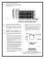
1
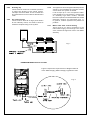
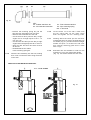
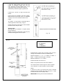
4.4
IMPORTANT NOTICE
4.4.1
If the combination boiler is to be fitted in a
timber framed building it should be fitted in
accordance with the British Gas Publication
Guide for Gas Installations in Timber Frame
Housing Reference DM2, If in doubt advice
must be sought from the local gas supplier. The
combination boiler may be installed in any room
or internal space, although particular attention
is drawn to the requirements of the current
I.E.E. Wiring Regulations, and in Scotland the
electrical provisions of the Building Regulations
applicable in Scotland. With respect to the
installation of the combnation boiler in a room
or internal space containing a bath or shower.
Where a room sealed appliance is installed
in a room containing a bath or shower, any
electrical switch or appliance control, utilising
mains electricity should be so situated that it
cannot be touched by a person using a bath or
shower.
A compartment used to enclose the combination
boiler MUST be designed and constructed
specifically for this purpose. An existing
cupboard, or compartment, may be used
provided it is modified accordingly Samples
of the CSI combination boiler have been
examined by B.G. Technology Notified Body,
and is certified to comply with the essential
requirements of the Gas Appliance,
Directive 90/396/EEC, the Low Voltage,
Directive 72/23/EEC and shows compliance
with the Electro Magnetic Compatibility,
Directive 89/336/EEC and are therefore
permitted to carry the CE Mark.
The appliance has been tested and approved
by the WRc as meeting the requirements of
G3 and L of the Building regulations and water
Bylaws Scheme - Approved Products.
4.5
GAS SUPPLY
4.5.1
A gas meter is connected to the service pipe
by the Local Gas Region or the Local Gas
Region contractor. An existing meter should
be checked preferably by the Gas Region to
ensure that the meter is adequate to deal with
the rate of gas supply required for all appliances
it serves. Installation pipes should be fitted in
accordance with BS 6891. Pipework from the
meter to the boiler must be of adequate size
(22 mm) min To within at least 3 metre of
the boiler (15 mm) min can then be used for
remaining pipe work to the appliance. A smaller
size than the boiler inlet gas connection should
not be used. The complete installation must be
tested for soundness as described in the above
Code.
N.B. if the gas supply for the boiler serves
other appliances ensure an adequate
supply is available both to the boiler and the
other appliances when they are in use at the
same time.
4.6
FLUE SYSTEM
4.6.1
The terminal should be located where dispersal
of combustion products is not impeded and with
due regard for the damage or discolouration
that might occur to building products in the
vicinity (see fig. 5).
The terminal must not be located in a place
where it is likely to cause a nuisance. In cold
and/or humid weather water vapour may
condense on leaving the flue terminal, the
effect of such steaming must be considered
The terminal must not be closer than 25 mm
(1 in) to any combustible material For protection
of combustibles, refer to BS 5440.1.
Where a flue terminal is installed less than
1000 mm. from a plastic, or painted gutter;
or 500 mm from painted eaves, an aluminium
shield 1000 mm long, should be fitted to the
underside of the gutter or painted surface.
Pluming will occur at the terminal so, where
possible, terminal positions which could cause
a nuisance should be avoided.
The flue must be installed in accordance with
the recommendations of BS 5440: Part 1.
IMPORTANT NOTES
For greater flue lengths see twin flue
instructions.
Flue must be positioned in a place not
likely to cause a nuisance.
IMPORTANT: The following notes are intended for
general guidance.
The boiler MUST be installed so that the terminal
is exposed to external air.
It is important that the position of the terminal
allows the free passage of air across it at all
tirnes.
Minimum acceptable spacing from the terminal to
obstructions and ventilation opening are specified
in Fig. 5.
Note positions: Due to the terminal design,
installation is possible with clearances less than
those specified in BS 5440, Part 1.
11