1
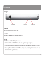
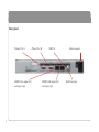
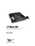
XLogic Delta-Link MADI HD
MADI Interface for Digidesign® HD Systems
Installation and User Guide
XLogic Delta-Link. This is SSL.
C o n te n ts
Safety and Installation Considerations
1. Introduction
XLogic Delta-Link MADI HD
Reading conventions
2. Overview
Front panel
Rear panel
3. Installation
4. Synchronization
Pro Tools HD card
®
Delta-Link MADI HD
WordClock / FrameClock
High Speed and SMUX modes
5. Sample Rates and I/O Mapping
I/O mapping and Sample Rate range
1
3
3
4
5
5
6
8
10
10
10
11
12
12
13
6. Pro Tools® Software
General information
Remote control of Delta-Link MADI HD settings
Known issues
17
17
19
21
7. Troubleshooting
24
Technical support
24
System Resources
8. Specifications
24
26
Safety and Installation Considerations
This section contains definitions, warnings, and practical information to ensure a safe working environment.
Please take time to read this section before installing or using this unit. Please do not dispose of these instructions.
General Safety
• Read these instructions.
• Keep these instructions.
• Heed all warnings.
• Follow all instructions.
• Do not use this apparatus near water.
• Do not expose this apparatus to rain or moisture.
• Clean only with dry cloth.
• Do not block any ventilation openings. Install in accordance with the manufacturer’s
instructions.
• Do not install near any heat sources such as radiators, heat registers, stoves or other
apparatus (including amplifiers) that produce heat.
• There are no user-adjustments, or user-serviceable items, inside this apparatus. Do not
remove the covers of this apparatus; doing so will invalidate your warranty.
• Adjustments or alterations to this apparatus may affect the performance such that
safety and/or international compliance standards may no longer be met.
Caution
• To reduce the risk of electric shock, do not perform any servicing other than that
contained in these Installation Instructions unless you are qualified to do so. Refer all
servicing to qualified service personnel.
Power Safety
• This apparatus is fitted with a universal power supply, approved and certified for
operation in this apparatus. There are no user-replaceable fuses.
• A power cord is supplied with this unit. Alternative power cords may be used if rated
2.5A or above and fitted with a 3-pin IEC320 connector and a 3-core cable.
• This apparatus must be connected to an earthed mains outlet. The earth core of the
power cord must always connect to the mains supply ground – the earth core forms
the safety earth and should not be removed for any reason.
• If an extension power cable or adaptor is used, ensure that the total power rating of
the power cable and/or adaptor is not exceeded.
• An external disconnect device is required for this apparatus; a detachable power cord
– as used for this apparatus – is a suitable disconnect device.
• An external over-current protection device is required to protect the power wiring to
this apparatus. In certain countries this function is supplied by use of a fused plug.
• All power wiring should be installed according to local wiring regulations.
• The mains outlet used for this apparatus should be located nearby and be easily
accessible.
• Unplug this apparatus during an electrical storm or when unused for long periods of
time.
Installation Notes
• When installing this apparatus, either fix it into a standard 19" rack or place the
apparatus on a secure level surface.
• Ensure that no strain is placed on the cables connecting to this apparatus. Ensure also
that such cables are not placed where they can be stepped on, pulled or tripped over.
• Do not operate this apparatus whilst it is covered or boxed in any way.
• Do not operate this unit with the covers removed.
1
2
1. Introduction
XLogic Delta-Link MADI HD
Congratulations on your purchase of the XLogic Delta-Link MADI HD! Please be assured that it will provide you with many
years of reliable service while delivering the pristine audio quality you expect from any Solid State Logic product.
The Delta-Link MADI HD is an elegantly styled, 1U high, rack mountable unit. The front panel design is reminiscent of the
rest of the XLogic Alpha-Link range… rather understated in this case: since the unit is controlled from the computer, the only
front panel controls are the power switch, the power LED and a lock indicator LED.
Using Delta-Link MADI HD you can hook-up a standalone, MADI compatible multi channel I/O and format conversion unit
to a Pro Tools® HD core or Pro Tools® HD Accel card(s). Solid State Logic has a number of such I/O units:
• XLogic Alpha-Link MADI-SX (64 MADI I/O, 12 stereo/24 mono AES/EBU I/O, 24 balanced analogue I/O).
• XLogic Alpha-Link MADI-AX (64 MADI I/O, 24 ADAT I/O, 24 balanced analogue I/O).
The Delta-Link MADI HD is also suitable for applications where Pro Tools® audio hardware is used with third party software
packages (e.g. Logic Pro 7).
IMPORTANT: Please register your XLogic Delta-Link MADI HD on our website. This will ensure that you receive
notification of future updates and other important information, and that your guarantee is registered. Registration will
also make you eligible for technical support.
The Solid State Logic home page is at: http://www.solidstatelogic.com
From there you can go to the Support page, which includes links to the Product Registration and Download pages. You
can also visit the Frequently Asked Questions (FAQ) area for any questions you might have or to contact tech support.
3
Reading conventions
Software menus
Where appropriate, to indicate a “path” under a Solid State Logic or Pro Tools® software menu, the following format will be
used; menu: Header|Submenu 1|Submenu 2|Submenu 3|Item.
Screenshots
The appearance of SSL or Pro Tools® software on your computer screen may be different from the screenshots in this manual.
This could be because you are using a different operating system or operating system version or because you are using different
display settings, etc.
Firmware Version
The information contained in this User Guide is correct for Delta Link firmware version V1.30 or greater.
4
2. Overview
Front panel
Power switch
Power switch
This switch is used to power the unit up or down.
Lock LED
Power LED
Power LED
This LED is lit when the Delta-Link MADI HD is switched on.
Lock LED
This LED indicates that a WordClock signal is received:
• It is lit when the Delta-Link MADI HD is receiving a stable signal at the required sample rate.
• It flashes slowly when the Delta-Link MADI HD is receiving a stable signal at an incorrect sample rate. (See Section 5.)
• It flashes quickly when the Delta-Link MADI HD is receiving no signal, an unstable signal, or a signal at a sample rate
that falls outside the acceptable boundaries.
5
Rear panel
Primary Port A
MADI Port A output (left)
and input (right)
6
Primary Port B
USB Port
MADI Port B output (left)
and input (right)
Mains connector
WordClock input
Primary Port A / Primary Port B
Each Pro Tools® HD port provides 32 input and output channels, regardless of sample rate.
MADI A / MADI B
The two MADI ports provide up to 64 input and output channels, depending on sample rate. Both MADI interfaces are fibre
optic using SC-type connectors; we offer a separate external MADI coaxial to optical converter solution to interface Delta-Link
MADI HD into coaxial systems.
USB
The USB interface can be used to control various settings of the Delta-Link MADI HD hardware and to update the internal
firmware. This interface is USB 1.0 compliant and uses a Style-A USB connector.
WordClock In
This input must be used to supply a clock reference signal to the Delta-Link MADI HD.
Power
The unit is powered by an internal, auto-switching power supply. The connector is an IEC 320 type.
7
3. Installation
The Delta-Link MADI HD package includes:
• The Delta-Link MADI HD unit.
• 2 of 0.9m (35") DigiLink cables.
• The mains connection cable.
• This manual.
NOTE: The maximum allowable length of cables required to connect the Digidesign® cards to the Delta-Link MADI HD
(DigiLink cables) varies as follows according to the sample rate being used:
• 48kHz operation: 1.8m (70")
• 96kHz operation: 0.9m (35")
• 192kHz operation: 0.45m (18")
If required, Delta-Link MADI HD can be rackmounted. It occupies 1U of rack space in a standard 19-inch rack.
It is assumed that your Pro Tools® HD system is already installed in the host computer (Windows PC or Mac OS X).
8
1. Connect Primary Port A of the Delta-Link MADI HD to Primary Port A of your Pro Tools® HD system and Primary Port
B of the Delta-Link MADI HD to Primary Port B of your Pro Tools® HD system via DigiLink cables supplied. The Pro
Tools® software can be used to control internal settings of the Delta-Link Madi HD. This functionality uses Primary Port
A only, so it is important that this connection scheme is followed.
WARNING!
Do not connect or disconnect the Delta-Link MADI HD to/from the Pro Tools® cards or power cycle the unit
while the Pro Tools® software is running. Doing so will loose all interface settings, recovery from which will
require each option to be toggled on the Pro Tools® I/O set up page – refer to Section 6.
2. Connect a suitable Word or Frame clock source to the WordClock input at the rear of the Delta-Link MADI HD.
(see overleaf)
3. Connect the mains cable to the mains connector of the Delta-Link MADI HD.
4. External devices may now be connected to the MADI inputs and outputs.
5. Power up the computer that hosts your Pro Tools® system, and power up the Delta-Link MADI HD (using the power
switch on the front panel).
9
4. Synchronization
Pro Tools® HD card
The Pro Tools® HD card is designed to operate as a Clock Slave, locking to a clock reference signal provided by the audio unit
connected to its primary port.
Delta-Link MADI HD
The Delta-Link MADI HD, like the Pro Tools® HD card, is designed to operate as a Clock Slave. Once the card and
Delta-Link MADI HD are connected together, they can be seen as a unit requiring an external clock reference signal. However,
this unit now has MADI ports, instead of the “Digital and Analogue” connections to other devices provided by Pro Tools®
interfaces.
Although a reference signal is embedded in the Primary port, the MADI connection requires a separate WordClock signal.
Therefore, the Delta-Link MADI HD is equipped with a WordClock input connector.
Depending on the type of unit that is connected to the MADI port, the sample rate will no longer change automatically when
a setting is selected in the PC or Mac software (because there is no command channel). Therefore, the sample rate must be set
manually at both ends (in the Pro Tools® software and on the hardware connected to the MADI port).
10
WordClock / FrameClock
The WordClock input can translate WordClock or FrameClock to the required Sample Rate. The “LOCK” LED on the front
panel indicates reception of a stable signal.
NOTE: When a “multiplexing” mode is used for digital audio transfers, the frame rate of the audio clock is equal to the
audio sample rate at up to 48kHz, half of the audio sample rate at up to 96kHz or a quarter of the audio sample rate at up
to 192kHz. The term “FrameClock” denotes an audio clock signal that is proportional but not always equal to the sample
rate, therefore:
• At 44.1kHz, 88.2kHz or 176.4kHz, the frame rate is 44.1kHz.
• At 48kHz, 96kHz or 192kHz, the frame rate is 48kHz.
NOTE: To understand this topic fully, it is important to read the AES MADI specification – AES 10 –2003 (www.aes.org).
11
5. Sample Rates and I/O Mapping
High Speed and SMUX modes
• Sampling frequencies up to 48kHz are designated as being in the “NFS range” (from NFs, Normal Frequency sampling).
• Sampling frequencies above 48kHz and up to 96kHz are in the “DFS range” (from DFs, Double Frequency sampling).
• Sampling frequencies above 96kHz and up to 192kHz are in the “QFS range” (from QFs, Quadruple Frequency
sampling).
At high sample rates (in the DFS and QFS ranges), the MADI interface can operate in either of two modes; High Speed or SMUX:
DFS range (88.2kHz to 96kHz)
The MADI interface can operate in High Speed or SMUX2 modes. In High Speed mode the MADI-embedded reference signal
has a frequency of 88.2kHz to 96kHz. In SMUX2 mode, the frequency is 44.1kHz to 48kHz.
QFS range (176.4kHz to 192kHz)
The MADI interface can operate in High Speed or SMUX4 modes. In High Speed mode, the MADI-embedded reference
signal has a frequency of 176.4kHz to 192kHz. In SMUX4 mode, the frequency is 44.1kHz to 48kHz.
NOTE: To understand this topic fully, it is important to read the AES MADI specification – AES 10 –2003 (www.aes.org).
12
I/O mapping and Sample Rate range
NFS range (44.1kHz to 48kHz): 64-48 “normal” mode
NFS range (44.1/48kHz)
Normal Mode
Two Primary Ports interact with one MADI Port.
Primary Port A, channel 01 ↔ MADI Port A, channel 01
Primary Port A, channel 32 ↔ MADI Port A, channel 32
Primary
Port A
Channel A
(1..32)
Primary Port B, channel 33 ↔ MADI Port A, channel 33
Primary Port B, channel 64 ↔ MADI Port A, channel 64
MADI A
Channel A
(1..64)
Primary
Port B
Channel B
(33..64)
MADI B
NOTE: The MADI Port B output signals duplicate the MADI Port A output signals, but the MADI Port B inputs are not
connected internally to the Primary Ports in this mode.
13
NFS range (44.1kHz to 48kHz): 64-48 “special” mode
NFS range (44.1/48kHz)
Special Mode
Two Primary Ports interact with two MADI Ports.
Primary Port A, channel 01 ↔ MADI Port A, channel 01
Primary Port A, channel 32 ↔ MADI Port A, channel 32
Primary
Port A
Channel A
(1..32)
Primary Port B, channel 33 ↔ MADI Port B, channel 33
Primary Port B, channel 64 ↔ MADI Port B, channel 64
MADI A
Channel A
(1..32)
MADI B
Channel A
(33..64)
Primary
Port B
Channel B
(33..64)
NOTE: The 64-48 special mode must be selected remotely via software. (For Pro Tools® see the information on page 19 and
table on page 20)
NOTE: This special mode is especially suitable for interfacing with the SSL Alpha-Link range of audio interfaces: two
Alpha-Link MADI audio interfaces can be connected to one Delta-Link MADI HD, providing 48 analogue input/output
channels and 16 digital input/output channels (AES/EBU or ADAT) at 96kHz.
14
DFS range (88.2kHz to 96kHz): 64-96 mode
DFS range (88.2/96 kHz)
Two Primary Ports interact with two MADI Ports.
Primary Port A, channel 01 ↔ MADI Port A, channel 01
Primary Port A, channel 32 ↔ MADI Port A, channel 32
Primary
Port A
Channel A
(1..32)
Primary Port B, channel 33 ↔ MADI Port B, channel 33
Primary Port B, channel 64 ↔ MADI Port B, channel 64
MADI A
Channel A
(1..32)
MADI B
Channel A
(33..64)
Primary
Port B
Channel B
(33..64)
15
QFS range (176.4kHz to 192kHz): 32-192 mode
QFS range (176.4/192 kHz)
One Primary Port interacts with two MADI Ports.
Primary Port A, channel 01 ↔ MADI Port A, channel 01
Primary Port A, channel 16 ↔ MADI Port A, channel 16
Primary Port A, channel 17 ↔ MADI Port B, channel 17
Primary Port A, channel 32 ↔ MADI Port B, channel 32
16
Primary
Port A
Channel A
(1..32)
MADI A
Channel A
(1..16)
MADI B
Channel A
(17..32)
Primary
Port B
6. Pro Tools Software
®
General information
The Delta-Link MADI HD can work with Pro Tools® HD systems running on a Windows PC or Macintosh OS X computer.
Using the Delta-Link MADI HD with the Pro Tools® software is generally straightforward. However, there are a few points
to be aware of:
• The Delta-Link MADI HD appears in the Pro Tools® software as four Digidesign® 192 I/O units, except when operating
at 176.4 or 192kHz, in which case it appears as two Digidesign® 192 I/O units.
• The MADI inputs and outputs appear in the Pro Tools® software as Analogue or Digital (AES/EBU or ADAT) inputs and
outputs belonging to these four Digidesign® 192 I/O units. Therefore, you will not find any MADI inputs or outputs listed
in the Hardware Setup page of the Pro Tools® software (select Setup|Hardware). Please use the inputs and outputs that
are listed, regardless of their denomination – they are really your MADI inputs and outputs – and do not select “None”.
17
The screenshot below was made using a Pro Tools® HD system with a single Delta-Link MADI HD which appears as a set of
192 I/O peripherals (see below, top left). All the inputs and outputs listed belong to this single unit.
18
Remote control of Delta-Link MADI HD settings
Some Delta-Link MADI HD system settings can be controlled via the Analog Out tab of the Pro Tools® software’s Hardware
Setup window (select Setup|Hardware).
19
In the Hardware Setup window, the “Output Trim” settings are irrelevant to the Delta-Link MADI HD because its inputs and
outputs are all digital. Therefore, they can be used to set various Alpha-Link parameters as follows:
Channel Number
If “B” is selected
MADI NFS mode
Normal
Special
Number of MADI channels
3
MADI DFS/QFS mode
5
Sample Rate Deviation
4
*2
If “A” is selected
1
2
*1
Parameter
WordClock input
56/28/14
SMUX
WordClock
Narrow*1
64/32/16
High Speed
FrameClock
(48kHz /44.1kHz)
Wide*2
Narrow deviation is typically used for Audio editing. The Lock LED on the front panel will light when the received
Wordclock is within ±0.5%. This mode is valid for both 56/28/14 and 64/32/16 channel modes.
Wide deviation is typically used for Video editing. In this mode, varispeed is allowed up to ±4.2% (all Sample Rates).
This mode is only valid for 56/28/14 channel mode.
Note: Selecting both wide deviation mode (±4.2%) and 64/32/16 channel mode is invalid and will result in poor audio
performance.
20
Known issues
Start up errors
When the Pro Tools® software starts up, it uses the settings defined during the previous session, e.g. number and type of Audio
Interfaces, I/O setup, etc.
If you have used a Legacy Audio Interface (defined through menu: Setup|Hardware), and then replaced its current Audio
Interfaces with the Delta-Link MADI HD, the Pro Tools® software will display the following error message: “DAE error -1125
was encountered”. This is because the Legacy Audio Interface cannot be detected anymore. After clicking “OK”, the Pro Tools®
software will close without allowing you to change the Hardware setup!
Solution 1. (Mac or PC)
• An easy way to get around this problem is to startup Pro Tools® with the Delta-Link MADI HD switched OFF. The
following message will eventually be displayed: “Unable to find an Audio Interface attached to..”. At this point, power
up the Delta-Link MADI HD and click “OK”. Pro Tools® will then continue its start up procedure.
Solution 2. (Mac Only)
• Another way to solve this problem is to delete the “DigiSetup.OSX” file and the “DAE prefs” folder in the
“Library/Preferences” folder. This will force Pro Tools® to start up using a default configuration (48kHz, limited
“Voices”, no Hardware knowledge...)
For either solution, now go to menu: Setup|Hardware and make sure all Legacy Interfaces are removed from the Peripherals
list (see over leaf).
21
The best way to ensure all Legacy Interfaces are removed is to click the name of a Legacy Audio Interface (e.g. 882/20 or
888/24) and to select “No Interfaces” from the “Interface” drop down box. After the Legacy Interfaces have been removed,
select the 192 I/O device, click the “Main” tab and select “Expansion I/O” in the “Port Settings” section. As a result, you will
see the second 192 I/O device appearing in the “Peripherals” list.
22
Playback Engine
The Delta-Link MADI HD provides up
to 64 input and output channels.
Therefore, the number of voices for the
Playback Engine may need to be
increased.
For instance, in order to playback and
record 64 tracks simultaneously at
96kHz, go to menu: Setup|Playback
Engine and select “128 voices”.
23
7. Troubleshooting
System Resources
The system resource usage can always be checked in the
Pro Tools® software under menu: Window|System Usage:
Firmware Updates
The Delta-link MADI HD features a USB connector on the
back panel to allow for firmware updates.
When a new firmware update is released, an update utility will
be available from the downloads section of the Solid State
Logic Support Website.
NOTE: The interface is USB 1.0 compatible only.
NOTE: Please do not switch the unit off, disconnect the
USB cable or switch off the controlling computer whilst
upgrading the firmwire. Doing so may leave the Delta-Link
MADI HD in an unusable state.
Technical support
If you encounter problems that you cannot solve, please check
out our online knowledge base at http://solid-state-logicen.custhelp.com for trouble shooting tips or to get assistance
from our technical support team.
24
Symptoms
The Delta-Link MADI HD
is not detected by the software.
There is no sound or there is
noise. The Lock LED flashes.
The Delta-Link MADI HD
is recognized by the Pro Tools
software and the Lock LED is lit.
However, there is no sound.
Bad audio.
Possible solutions
Check that the Delta-Link MADI HD is connected to the mains supply and that the
Power switch is in the On position (the Power LED should be lit). Check the
condition of the mains cable. Check that the Delta-Link MADI HD is connected to
the Pro Tools® HD cards via suitable DigiLink cables and check the condition of
these cables.
Check that the Delta-Link MADI HD is receiving a suitable WordClock or
FrameClock signal compatible with the Sample Rate selected in Pro Tools®.
Check the MADI connections and the condition of the MADI cables. In particular,
make sure that the MADI inputs of the Delta-Link MADI HD are connected to
MADI outputs and vice versa of the other device(s). Please note that MADI cables
are sometimes marked “A” at one end and “B” at the other end, which can be
confusing and sometimes results in two MADI inputs or two MADI outputs being
interconnected by mistake.
This may be caused by a MADI mode mismatch between the Delta-Link MADI HD
and the device connected to its MADI ports (e.g. a unit from the SSL Alpha-Link
MADI series). The MADI format allows either 56/28/14 or 64/32/16 input/output
channels, depending on the selected Sample Rate. Devices connected via MADI
must use the same MADI mode! (For an SSL Alpha-Link MADI interface, please
refer to the corresponding manual.)
25
8. Specifications
Physical *
Depth
Height
175mm / 7"
casing only
438mm / 17.25"
482mm / 19"
casing only
inc’ rack ears
44.5mm / 1.75" (1 RU)
Width
2.7kg / 6 pounds
Control
USB
Boxed size
320mm x 550mm x 80mm
12.75" x 21.75" x 3.25"
* All values are approximate
Environmental
Temperature
Relative
Humidity
Vibration
Shock
Altitude
(above sea level)
26
Digital I/O
Primary Port A,
Primary Port B
< 15 Watts
2.2kg / 5 pounds
Boxed weight
Power
MADI A
MADI B
Weight
Power
Connections
Operating:
Non-operating:
Max. gradient:
Operating:
Non-operating:
Max. wet bulb:
(non-condensing)
+5 to 30 deg. C
–20 to 50 deg. C
15 deg. C/hour
20 to 80 %
5 to 90 %
29 deg. C
Operating:
Non-operating,
power off:
< 0.2 G (3 – 100Hz)
Operating:
Non-operating:
0 to 3000m
0 to 12000m
Operating:
Non-operating:
< 0.4 G (3 – 100Hz)
< 2 G (10ms max.)
< 10 G (10ms max.)
WordClock
Performance
Quantisation
Sample Rates
IEC320 3-pin connector, 100 – 240 Vac, 50 – 60 Hz
26-pin Hirose DXM series socket
Twin SC type chassis sockets
Glass Multimode Fibre: 50/125µ
Standard B-type chassis socket.
75Ω BNC, Zin = 75Ω, 3V3/5V TTL compatible.
24bit, fixed point
44.1kHz
48kHz
88.2kHz
96kHz
176.4kHz
192kHz (all ±0.5% for 64/32/16 MADI channels,
±4.2% for 56/28/14 MADI channels)
This equipment has been tested and found to comply
with the limits for a Class B digital device, pursuant
to part 15 of the FCC Rules. These limits are
FOR HOME OR OFFICE USE
designed to provide reasonable protection against
harmful interference in a residential installation. This
equipment generates, uses and can radiate radio frequency energy and, if not installed and
used in accordance with the instructions, may cause harmful interference to radio
communications. However, there is no guarantee that interference will not occur in a
particular installation. If this equipment does cause harmful interference to radio or
television reception, which can be determined by turning the equipment off and on, the
user is encouraged to try to correct the interference by one or more of the following
measures:
Tested To Comply
with FCC Standards
• Reorient or relocate the receiving antenna.
• Increase the separation between the equipment and receiver.
• Connect the equipment into an outlet on a circuit different from that to which
the receiver is connected.
• Consult the dealer or an experienced radio/TV technician for help.
Instructions for Disposal of WEEE by Users in the European Union
The symbol shown here is on the product or on its packaging, which
indicates that this product must not be disposed of with other waste. Instead,
A
it is the user’s responsibility to dispose of their waste equipment by handing
AA
A
AA
it over to a designated collection point for recycling of waste electrical and
electronic equipment. The separate collection and recycling of your waste
equipment at the time of disposal will help to conserve natural resources and ensure that
it is recycled in a manner that protects human health and the environment. For more
information about where you can drop off your waste equipment for recycling, please
contact your local city office, your household waste disposal service or where you
purchased the product.
Standards Conformance
This apparatus fully conforms with the current protection
requirements of the European community council directives on
EMC and LVD.
Warranty
Pursuant to the Solid State Logic Terms and Conditions under European consumer law
the purchaser has full statutory warranty rights for two years from the date of delivery
of the product. The warranty is valid only in those Member States of the European Union
(EU) who have adopted the applicable EU law into their national legislation. The
applicable national legislation governing the sale of consumer goods is not affected by
this warranty. Warranty claims will only be accepted if the purchased product has been
used for its intended purpose. Any purchased product used for an unintended purpose will
not be eligible for warranty protection. For all warranty inquiries or claims please address
the claim to us if the purchase was directly from us or otherwise to the dealer from which
you purchased the product within a period of two months from the date on which you
detected its lack of conformity with the terms of the warranty. Please include your
original proof of purchase when initiating the claim.
Out of Warranty Repairs
In the event of a fault arising after the warranty period has expired the unit should be
returned to Solid State Logic either directly or via your local dealer. You will be charged
for the time spent on the repair (at Solid State Logic's current repair rate) plus the cost
of parts and shipping. Note that no units can be accepted for repair without prior
arrangement (see below).
All Returns
• No unit will be accepted for repair by Solid State Logic unless accompanied by a
valid RMA (Return Material Authorisation) number, obtainable from Solid State
Logic prior to shipping.
• All units should be shipped to Solid State Logic in suitable rigid packaging – Solid
State Logic cannot be held responsible for any damage caused by shipping units in
other packaging. In such cases Solid State Logic will return the unit in a suitable
box, which you will be charged for.
• Do not include the power cable, manual or any other items – Solid State Logic can
not guarantee to return them to you.
27
Visit SSL at URL: http://www.solid-state-logic.com
82S6ALS20D
© Solid State Logic
All Rights reserved under International and Pan-American Copyright Conventions
VHD, VHD logo, Xlogic, XLogic Delta and Xlogic Alpha are trademarks of Solid State Logic
All other product names and trademarks are the property of their respective owners and are hereby acknowledged
No part of this publication may be reproduced in any form or by any means, whether mechanical or
electronic, without the written permission of Solid State Logic, Oxford, OX5 1RU, England
As research and development is a continual process, Solid State Logic reserves the right to change
the features and specifications described herein without notice or obligation.
Solid State Logic cannot be held responsible for any loss or damage arising directly or indirectly
from any error or omission in this manual.
E&OE