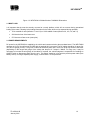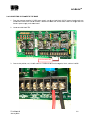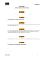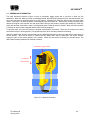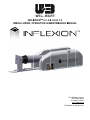
1
M INFLE EXIONTM 2.3, 4.5 5, 6.0 & 7.5 INS STALLAT TION, OPERATION & M MAINTEN NANCE M MANUAL The Will-Bu urt Company 169 S.. Main Street Orrville e, OH 44667 www.willburt.com TP-4 4976401-B, Ja anuary 2014 INFLEXIONTM Inflexion™ Warranty Will-Burt warrants its Inflexion™ masts to be free from defects in material and workmanship for a period of two (2) years, with such time period running from the date of shipment by Will-Burt. Will-Burt shall not be responsible for any damage resulting to or caused by its products by reason of failure to properly install, maintain or store the product; use of the product in a manner inconsistent with its design; unauthorized service, alteration of products, neglect, abuse, accident, or acts of God,. This warranty does not extend to any component parts not manufactured by Will-Burt; provided, however, WillBurt’s warranty herein shall not limit any warranties by manufacturers of component parts which extend to the buyer. THE FOREGOING WARRANTY IS IN LIEU OF ALL OTHER WARRANTIES, AND NO REPRESENTATIONS, GUARANTEES OR WARRANTIES, EXPRESS OR IMPLIED, INCLUDING BUT NOT LIMITED TO, A WARRANTY OF MERCHANTABILITY, FITNESS FOR A PARTICULAR PURPOSE, OR NONINFRINGEMENT ARE MADE BY WILL-BURT IN CONNECTION WITH THE MANUFACTURE OR SALE OF ITS PRODUCTS. NO EMPLOYEE, DISTRIBUTOR, OR REPRESENTATIVE IS AUTHORIZED TO CHANGE THIS WARRANTY IN ANY WAY OR GRANT ANY OTHER WARRANTY ON BEHALF OF WILL-BURT. Claims for defects in material and workmanship shall be made in writing to Will-Burt within thirty (30) days of the discovery of defect. Failure to provide notice as required hereby shall be conclusive evidence that the product was in conformity with the warranty, and Will-Burt shall be released from any and all liability relating to the product. WillBurt may either send a service representative or have the product returned to its factory at Buyer's expense for inspection. If judged by Will-Burt to be defective in material or workmanship, the product will be replaced or repaired at the option of Will-Burt, free from all charges except authorized transportation. THE REMEDIES OF BUYER SET FORTH HEREIN ARE EXCLUSIVE AND ARE IN LIEU OF ALL OTHER REMEDIES. THE LIABILITY OF WILL-BURT WHETHER IN CONTRACT, TORT, UNDER ANY WARRANTY, OR OTHERWISE, SHALL NOT EXTEND BEYOND ITS OBLIGATION TO REPAIR OR REPLACE, AT ITS OPTION, ANY PRODUCT OR PART FOUND BY WILL-BURT TO BE DEFECTIVE IN MATERIAL OR WORKMANSHIP. WILL-BURT SHALL NOT BE LIABLE FOR COST OF INSTALLATION AND/OR REMOVAL, OR BE RESPONSIBLE FOR DIRECT, INDIRECT, SPECIAL OR CONSEQUENTIAL DAMAGES OF ANY NATURE. TP-4976401-B January 2014 iii INFLEXIONTM Document History Manual Version Date Remarks TP-4976401 00 11/12/2013 INITIAL RELEASE A 12/3/2013 Updated warranty page. B 01/06/14 Clarify power requirements (section 1.6), emergency stow procedure (section 3.2) TP-4976401-B January 2014 iv INFLEXIONTM TABLE OF CONTENTS SAFETY SUMMARY..................................................................................................................................... vii 1. INTRODUCTION 1-1 1.1 Safety Precautions ................................................................................................................................ 1-1 1.2 Document Introduction .......................................................................................................................... 1-1 1.3 INFLEXION Description ........................................................................................................................ 1-1 1.4 Dimensions ........................................................................................................................................... 1-2 1.5 Mast Load ............................................................................................................................................. 1-3 1.6 Power Requirements ............................................................................................................................ 1-3 2-4 2. INSTALLATION 2.1 Introduction ........................................................................................................................................... 2-4 2.2 Tools and Materials Required for Installation ....................................................................................... 2-4 2.3 Unpacking ............................................................................................................................................. 2-5 2.4 Attaching to vehicle ............................................................................................................................... 2-5 2.5 Connecting DC Power to the Base ....................................................................................................... 2-6 2.6 Pre-operational Check .......................................................................................................................... 2-7 2.7 Functional Test ..................................................................................................................................... 2-7 3. OPERATING INSTRUCTIONS 3-1 3.1 General Mast Operation........................................................................................................................ 3-2 3.2 Emergency Stow (Loss of Power): ....................................................................................................... 3-3 4. MAINTENANCE AND SERVICE INSTRUCTIONS 4-4 4.1 Introduction ........................................................................................................................................... 4-4 4.2 Cleaning the INFLEXION ...................................................................................................................... 4-4 4.3 Adjustments .......................................................................................................................................... 4-4 4.4 Troubleshooting .................................................................................................................................... 4-6 TP-4976401-B January 2014 v INFLEXIONTM LIST OF ILLUSTRATIONS Figure 1-1 Figure 1-2 Figure 2-1 Figure 3-1 Figure 3-2 Figure 4-1 Figure 4-2 INFLEXION Mast Major Components (INFLEXION 4.5, model 720378040 shown) .............. 1-1 INFLEXION 4.5 Model Number 722069001 Dimensions ........................................................ 1-3 INFLEXION 4.5 Mounting Hole Pattern ................................................................................... 2-5 Hand-held Controller ............................................................................................................... 3-2 Emergency Stow Allen Screw Location ................................................................................... 3-3 Proximity Switches .................................................................................................................. 4-4 Status LEDs on Base Board .................................................................................................... 4-8 LIST OF TABLES Table 2-1 Tools and Materials Required for Installation ........................................................................... 2-4 Table 4-1 Troubleshooting Table .............................................................................................................. 4-8 TP-4976401-B January 2014 vi INFLEXIONTM SAFETY SUMMARY SIGNAL WORD DEFINITION Per the ANSI Z535.4 standard, the following signal words and definitions are used to indicate hazardous situations: DANGER indicates an imminently hazardous situation that, if not avoided, will result in death or serious injury. WARNING indicates a potentially hazardous situation that, if not avoided, could result in death or serious injury. CAUTION indicates a potentially hazardous situation that, if not avoided, may result in minor or moderate injury. It is also used to alert against unsafe practices. GENERAL SAFETY PRECAUTIONS The following are general safety precautions that are not related to any specific procedures and therefore do not appear elsewhere in this publication. These are recommended precautions that personnel must understand and apply during many phases of operation and maintenance. Electrocution Hazard! Contact with high voltage will result in death or serious injury. Observe general safety precautions for handling equipment using high voltage. Do not locate or operate mast near electrical lines, cables or other unwanted sources of electricity. Do not operate mast in lightning. Be certain electrical cables are undamaged and properly terminated. Always disconnect power before performing service, repair or test operations. Safety Instruction - Read Manual! Failure to follow operating instructions could result in death or serious injury. Read and understand the operator’s manual before using the mast. Tip Over Hazard! Mast tip over could result in death or serious injury. Do not operate in high winds. Operate on level ground only. Stand clear of mast and mast payload during operation. Be certain mast is level and secure before and during installation, operation and maintenance. Safety Instruction - Trained Personnel Only! Death or serious injury could result if proper inspection, installation, operation and maintenance procedures are not observed. Installation, operation and maintenance to be performed by trained and authorized personnel only. Proper eye protection should be worn when servicing the mast. Health and Safety Hazard! Solvent used to clean parts is potentially dangerous. Avoid inhalation of fumes and also prolonged contact to skin. Safety Instruction-Do not look at lights! Do not look directly into lights when they are illuminated. Temporary impairment or permanent vision damage could occur. TP-4976401-B January 2014 vii INFLEXIONTM SPECIFIC SAFETY PRECAUTIONS The following are safety precautions that are related to specific procedures and therefore appear elsewhere in this publication for emphasis. These are recommended precautions that personnel must understand and apply during specific phases of installation, operation and maintenance. Safety Instruction-Operation! For outdoor use only. Do not use in areas that have been classified as hazardous as defined in Article 500 of the National Electric Code. Crush Hazard! Death or serious injury could result if mast fails suddenly. Do not stand directly beneath the mast or its payload. Be certain payload is properly installed and secured. Burst Hazard! Over pressurizing mast will trip safety valve and could result in death or serious injury. Do not exceed maximum operating pressure of 20 psi (138 kPa) for Standard Duty masts. Keep personnel clear of safety valve exhaust direction. Fire Hazard! Cleaning solvent, used for maintenance, is flammable and can be explosive resulting in death or serious injury. Do not smoke. Use cleaning solvent in a well-ventilated area. Keep cleaning solvent away from ignition sources. Always store cleaning solvent in the proper marked container. Relocation Hazard! Relocating the mast during operation or after being raised could result in death or serious injury. Do not relocate the mast during operation or while raised. This applies especially to masts mounted to vehicles. Operate the mast only if the vehicle is stationary and the vehicle engine is off. Mounting Structure Hazard! Mounting mast into a structure unable to resist the forces generated from customer-specific loading scenario could result in death or serious injury and could damage the mast. Before operation, be certain mounting structure is capable of resisting forces generated from all loading and environmental conditions, including, but not limited to, mast size and weight, payload size and weight, sail size, wind speed, guy line arrangement, support bracket or roof line location and base plate assembly. Electrocution Hazard! Do not touch live wires. Death or serious injury could result. Safety Instruction – Operation! Make sure all power has been disconnected prior performing maintenance. Safety Instruction -Trained Personnel Only! Only trained and qualified personnel should perform installation, adjustments, and servicing. Only a properly trained and qualified certified electrician should perform electric installations and service. TP-4976401-B January 2014 viii INFLEXIONTM When relamping an installed fixture, make sure all power to fixture is off and that the fixture is cool Safety Instruction – Operation! At all times prior to mast operation, insure that: 1.) 2.) 3.) 4.) 5.) 6.) The mast area is free of personnel and mechanical obstruction; All electrical cables are undamaged and properly terminated; The operator must have full view of the mast during use; Any transit tie-downs on the payload have been removed; The vehicle is not moving; The area above the mast is free of mechanical obstructions. Safety Instruction-Operation! Lamps are extremely hot and should not come into contact with people or combustible and/or explosive materials. Do not operate if breakage occurs or unit is knocked over. Entanglement Hazard! Tangled cables can cause equipment damage. Ensure control cables are not tangled and are free to pay out as mast is raised. Safety Instruction – Operation! Do not operate the mast during an electrical storm. Lifting Hazard! Manually lifting over 55 lb (25kg) is prohibited. In the UK, all lifting equipment must be thoroughly examined annually by a competent person according to the Lifting Operations and Lift Equipment Regulations 1998. Equivalent regulations exist in other EU states. Safety Instruction – Operation! All operators must read the Operation section of this manual and be properly trained. TP-4976401-B January 2014 ix INFLEXIONTM CHAPTER 1 INTRODUCTION 1.1 SAFETY PRECAUTIONS Refer to the Safety Summary for precautions to be observed while operating or servicing this equipment. 1.2 DOCUMENT INTRODUCTION This document covers installation, operation, maintenance, and troubleshooting for the INFLEXION masts. The manual should be reviewed in its entirety. Contact the Will-Burt factory with any questions before performing any procedures outlined in this manual. The INFLEXIONTM 1.5, 2.3, 4.5, 6.0, and 7.5 masts will be referred to as the “INFLEXION” mast in this manual. 1.3 INFLEXION DESCRIPTION The INFLEXION mast is a transportable platform elevation system which serves as a platform for communications antennae, camera, and other payloads. The unit is designed for installation on any vehicle for the purpose of providing temporary communications, or surveillance. See Figure 1-1 for identification of the major components of the INFLEXION mast. Base Covers (base board and actuator inside) Top Three Not Used Platform Saddle Optional Nycoil Mast Compressor Exhaust DC Power In or Handheld Controller Figure 1-1 INFLEXION Mast Major Components (INFLEXION 4.5, model 720378040 shown) TP-4976401-B January 2014 1-1 INFLEXIONTM 1.4 DIMENSIONS Dimensions and mounting hole locations for INFLEXION are shown. Please refer to product literature or www.willburt.com for additional information including length, width and height information. MODEL TP-4976401-B January 2014 DIM "X" inch [mm] 4.5 METER 66 5/8 [1692.3] 6.0 METER 79 7/8 [2028.8] 7.5 METER 94 3/8 [2397.1] 1-2 INFLEXIONTM Figure 1-2 INFLEXION 4.5 Model Number 722069001 Dimensions 1.5 MAST LOAD It is important that the mast be securely mounted to a sturdy platform, which will not overturn during operational loading of the mast. Following is the loading information for the mast, which can be expected during operation: 75 lb at saddle of mast (Inflexion 1.5 and 2.3) or 120 lb saddle of mast (Inflexion 3.0, 4.5, 6.0, and 7.5) 200 lb at the front of the base cover 575 lb at rear of base cover (mast pivot) 1.6 POWER REQUIREMENTS DC power for the INFLEXION is supplied by the vehicle and customer-wired to the mast base board. The INFLEXION operates at 12 VDC, but will accept 24 VDC with the optional 24/12 converter. The DC cables should be 12 gauge (for 12V) and 16 gauge (for 24V). Long runs of cable can introduce power loss. There is a 35-40 amp inrush to the motor (depending on the length and gauge of the wires) that drops to 6-7 amps in 300mS. For long runs, it may be necessary to increase the wire gauge of the cables. If required, the vehicle-integrator is responsible for installing an ON/OFF switch to disconnect power from the unit. This switch should be in line with the positive power cable (from battery source). If using a separate power supply, it should have a 10 amp minimum. TP-4976401-B January 2014 1-3 INFLEXIONTM CHAPTER 2 INSTALLATION Safety Instruction -Trained Personnel Only! Only trained and qualified personnel should perform installation, adjustments, and servicing. Only a properly trained and qualified certified electrician should perform electric installations and service. Safety Instruction -Trained Personnel Only! Only trained and qualified personnel should perform installation, adjustments, and servicing. Only a properly trained and qualified certified electrician should perform electric installations and service. Lifting Hazard! Manually lifting over 55 lb (25kg) is prohibited. In the UK, all lifting equipment must be thoroughly examined annually by a competent person according to the Lifting Operations and Lift Equipment Regulations 1998. Equivalent regulations exist in other EU states. Safety Instruction – Installation! The INFLEXION should be installed on a location that is out of reach from unauthorized personnel. 2.1 INTRODUCTION The INFLEXION has been designed to provide for ease of installation. This section of the manual provides the procedures that must be followed to ensure a successful installation. Be sure to read and understand the entire installation procedure before you begin. 2.2 TOOLS AND MATERIALS REQUIRED FOR INSTALLATION Table 2-1 provides a list of tools and materials required to install and test the INFLEXION. Wrenches Crimping tool or Solder set Screwdrivers Wire cutter/stripper ½ inch or M12 Mounting Hardware (6 each) Multimeter (to verify power is turned OFF) Torque wrench Clean Shop Rags Drill Hoist (minimum 250 lb capacity) Table 2-1 Tools and Materials Required for Installation TP-4976401-B January 2014 2-4 INFLE EXIONTM 2.3 3 UNPACKIN NG Un npack the INFLEXION as fo ollows: 1. Carefully open and rem move all parts s from shippin ng container. 2. Lift the un nit from the shipping conta ainer by the ba ase tube at th he center of g gravity of the m mast shown b by the symbol. 3. Inspect fo or any shippin ng damage. If I damage has occurred, n notify carrier. 4. Be sure that t all compo onents are inc cluded and that the require ed tools are re eadily availab ble. 2.4 4 ATTACHIN NG TO VEHIC CLE If th he INFLEXIO ON is mounted d in a well on n a vehicle, be e certain that adequate dra ainage is provided. A min nimum of (4) dra ain holes (one e per corner) at least half inch in diame eter is recomm mended to be e drilled in the e well around d the unit so tha at water drains out of the well. w While th he unit has be een designed d to withstand d adverse envvironmental cconditions, it can nnot be subm merged. 9/1 16” bolt holes will be needed to mount mast m (Figure 2-1) to the ve ehicle. It is im mportant thatt the surface be flat such tha at the saddle and base pla ate are in the same plane. The areas tto which the u unit is mounted must be rreinforced to witthstand opera ating loading. Torque all hardware h as appropriate ffor its materia al and size. T There are (3)) unplugged stra ain relief hole es in the side of the base fo or cable entry y. Figure F 2-1 INFLE EXION 4.5 Mo ounting Hole Pattern Show wn Se ee section 1.4 4 for other ho le patterns. 401-B TP-49764 January 2014 2 2-5 INFLE EXIONTM 2.5 5 CONNECTING DC POW WER TO THE BASE 1. From the customer supplied 12 VDC power supply, run th he red and black 12V DC power wires tthrough one of the east AWG 12 e strain reliefs s in the side of o the base. Ensure E the ca ables are at le 2 and no long ger than 50ft from the t power sup pply to the ba ase board. 2. Locatte terminal blo ock TB3. Term minal Block TB3 3 3. Connect the positiv ve, red, 12 VD DC cable to 7 PWR and co onnect the ne egative, black, cable to 8 C COM. 401-B TP-49764 January 2014 2 2-6 INFLEXIONTM 4. Upon receipt of the INFLEXION, the hand-held controller should already be wired to the green base board connector. 2.6 PRE-OPERATIONAL CHECK Before beginning installation, make certain that the area is free of overhead power lines and other unwanted sources of electricity. Follow OSHA safety regulations when working near energized power lines. Be sure to allow sufficient clearance on all sides of mast to allow for side sway. This mast is for outdoor use only. Do not use in areas that have been classified as hazardous as defined in Article 500 of the National Electric Code. Do not use in the presence of flammable gases or liquids such as paint, gasoline or solvents. Do not use in areas of limited ventilation or where high ambient temperatures are present. Contact with combustible materials can cause ignition resulting in fire or explosion. Before operating the INFLEXION, be sure that there are no overhead obstructions and that there are no power lines within 20 feet of the mast. Visually inspect the unit for any damage. If damage is apparent, do not use the mast. Have it serviced prior to use. Check for any objects which might obstruct motion of the mast or cause binding. Remove any material that may hinder mast function. 2.7 FUNCTIONAL TESTS To test the installation, proceed as follows. If any part of the testing fails, check the LEDs on the base board as described in Section 4.4: 1. Check for proper clearance above the mast. 2. Press and hold the “Mast Up” button until the mast is fully deployed. The mast should raise to 90o then go fully deployed. There is no Auto-up feature. 3. Release the “Mast Up” button. Press and hold the “Mast Down” button. The mast should lower to 90o then stow and turn power off. There is no Auto-stow feature. TP-4976401-B January 2014 2-7 INFLEXIONTM CHAPTER 3 OPERATING INSTRUCTIONS All operators must read the Operation section of this manual and be properly trained. Keep personnel clear of mast while during operation. For outdoor use only. Do not use in areas that have been classified as hazardous as defined in Article 500 of the National Electric Code. Do not use in the presence of flammable gases or liquids such as paint, gasoline or solvents. Do not use in areas of limited ventilation or where high ambient temperatures are present. Contact with combustible materials can cause ignition resulting in fire or explosion. Before operating, make certain that the area is free of overhead power lines and other unwanted sources of electricity. Be sure to allow sufficient clearance on all sides of mast to allow for side sway. Do not move vehicle until mast has been securely stowed. TP-4976401-B January 2014 3-1 INFLEXIONTM 3.1 GENERAL MAST OPERATION The mast hand-held controller (Figure 3-1).has a momentary toggle switch and a cord that is wired into the baseboard. When the “Mast Up” button is pressed and held, the INFLEXION operates the DC powered actuator and drives the mast from the stowed position to the 90o position. Releasing the “Mast Up’ switch at any time stops mast motion. Note there is no Auto-up feature to automatically raise the mast to 90o. When at 90o, the 90o proximity switch detects the magnet in the actuator arm and stops further driving of the actuator. Pressing and holding the “Mast Up” switch will raise the mast until the mast is fully deployed and the mast up switch is sensed. When the mast up switch is sensed, air into the mast is stopped and the mast is left fully deployed. To stow the mast, you must first ensure the payload is positioned to be stowed. There are no controls on the hand held remote to pan or tilt the payload. The payload may have to be manually positioned for stowing. When the “Mast Down” button is pressed and held, the INFLEXION releases air from the mast and the mast lowers to the 90o position. Once the 90o sensor is reached and the “Mast Down” switch is held down, the electric actuator lowers the mast to the stowed position in the saddle. When the stow switch is sensed, the actuator stops. The INFLEXION remains powered until manually turned off. Momentary Toggle Switch UP Position Down Position Figure 3-1 Hand-held Controller TP-4976401-B January 2014 3-2 INFLEXIONTM 3.2 EMERGENCY STOW (LOSS OF POWER): Make sure all power has been disconnected from the INFLEXION prior to manually lowering mast. In the event of power loss, the INFLEXION mast will vent and lower automatically but the mast will not return to its fully stowed horizontal position. If possible, this must be accomplished manually and must be done with extreme caution. It may be necessary to manually pan the payload so that when it is manually stowed, the payload does not make contact with the mounting surface or the saddle. Consult payload manufacturer to determine if best way to move the payload without power. To emergency stow the mast, proceed as follows: 1. Remove the base access cover. 2. Make sure all power has been disconnected from the system by turning all breakers to the OFF position. 3. Ensure your payload is secure and may by safely lowered. 4. Remove the base cover. 5. Remove the 6mm Allen (set screw) on the end of the actuator cover (Figure 3-2 Emergency Stow Allen Screw Location). 6. Place a long 6mm Allen wrench into the hole to reach the 6mm Allen-head drive screw. A socket Allen wrench may be used but care must be taken not to damage the adjacent air compressor. 7. Turn the socket Allen wrench clockwise to lower the mast. Lower the mast until it seats firmly in the saddle. 8. Replace the 6mm Allen set screw. 9. Replace the right side base cover. Set Screw Figure 3-2 Emergency Stow Allen Screw Location TP-4976401-B January 2014 3-3 INFLEXIONTM CHAPTER 4 MAINTENANCE AND SERVICE INSTRUCTIONS 4.1 INTRODUCTION This section of the manual describes routine maintenance procedures and covers general service information. 4.2 CLEANING THE INFLEXION The exterior of the INFLEXION base should be wiped down periodically to remove dirt and road grime using a soft cloth or sponge and a mild solution of soapy water. 4.3 ADJUSTMENTS The proximity switches (Figure 4-1) are intended to stop the actuator when the mast is at 90o and when it is stowed. It senses the position of the mast as it rotates on the clevis assembly and signals the base circuit board to stop when the actuator is in the correct position. NIGHTSCAN CHIEF Figure 4-1 Proximity Switches TP-4976401-B January 2014 4-4 INFLEXIONTM Adjusting the 90o Proximity Switch Before delivery of a new INFLEXION, all switches are properly set and tested and normally no switch adjustment is necessary. However, if the 90o switch needs adjusted, like after the actuator was replaced, follow these steps to adjust the 90o switch: 1. Make certain that the INFLEXION base is level. 2. Remove the base side cover. 3. Loosen the upper jam nut to lower the switch approximately 1/8”. 4. Raise the mast to 90o by holding the “Mast Up” button until the mast is at 90o. 5. Check that the mast is at 90o by using a level and also ensuring that the mast is square to the sheet metal side plate on the base. A value in the range of 89.5o to 90.5o is acceptable. 6. Raise the 90o switch until it senses the actuator. This will be indicated by the status LED on the base circuit board (Figure 4-2). 7. Secure the switch in position using the upper and lower jam nuts. 8. Raise and lower the mast several times, checking that the mast is plumb each time and adjust the switch if necessary. 9. Replace the cover. Adjusting the Stow Proximity Switch Before delivery of a new INFLEXION, all switches are properly set and tested and normally no switch adjustment is necessary. However, if the stow switch needs adjusted, like after the actuator was replaced, follow these steps to adjust the stow switch: 1. Make certain that the INFLEXION base is level. 2. Remove the base side cover. 3. Loosen the upper jam nut to lower the switch approximately 1/8”. 4. Raise the mast to 90o by holding the “Mast Up” button until the mast is at 90o. 5. Hold the “Mast Down” button until the mast stows firmly into the saddle then release the “Mast Down” button. 6. With the mast stowed, carefully grasp the payload and attempt to slowly lift the payload off the saddle. If the saddle is not snug into the saddle, repeat steps 4 through 6 until the mast is firmly in the saddle. 7. Secure the switch in position using the upper and lower jam nuts. 8. Raise and lower the mast several times, checking that the mast is stowed each time and adjust the switch if necessary. 9. Replace the cover. TP-4976401-B January 2014 4-5 INFLEXIONTM 4.4 TROUBLESHOOTING Refer to Table 4-1 troubleshoot INFLEXION issues. WARNING: Only trained and qualified personnel should install, adjust, service and use INFLEXION. WARNING: Before troubleshooting, read the operating instructions and the safety summary. Always obey the warnings in the operating instructions. TP-4976401-B January 2014 4-6 INFLEXIONTM LED TP-4976401-B January 2014 Definition Power 12V is at the base board Mast active Mast is out of the saddle Lights active Mast is at 90 Tilt Up or Down Not Used Pan Right or Left Not Used Not 90 Deg Mast is not at 90 RCP active Not Used Not up Always lit when the mast is at 90 RCP run Not Used Down Not Used Full lights Not Used Up input Mast up key pressed Down input Mast down key pressed Half lights Not Used o o o 4-7 INFLEXIONTM Figure 4-2 Status LEDs on Base Board PROBLEM Actuator is not functioning at all. Actuator is not functioning properly in the UP direction. Actuator is not functioning properly in the DOWN direction CAUSE EVIDENCE Blown fuse FU1 or FU2 on circuit board. No status LEDs are lit on the control board. MAST UP/DOWN switch in remote Operator Station is defective. Neither the “UP INPUT” nor the “DOWN INPUT” status LEDs light when the corresponding switch is activated. Actuator is defective. Contact Customer Service. MAST 90° limit switch is misadjusted or defective. The “NOT 90 DEG” status LED is not lighted. MAST UP switch in Remote Operator Station is defective. The “UP INPUT” status LED does not light when the switch is activated. Magnetic (MAST RETRACTED) limit switch is misadjusted or is defective. The “NOT 90 DEG.” Status LED is not lighted. MAST DOWN switch in remote Operator Station is defective. The “DOWN INPUT” status LED does not light when the switch is activated. Table 4-1 Troubleshooting Table TP-4976401-B January 2014 4-8