1
VIEßMANN Group
Issue 2010-01
5368 463
CHP accessory range
Subject to changes due to technical improvements
CHP accessory range – 01/2010 5368 463
01/2010
ESS Energie Systeme & Service GmbH
1
Imprint
Subject to technical modifications
Constant development may lead to minor deviations in
the illustrations, functional steps and specifications from
those described/shown.
Updating your documentation
Please let us know if you have any suggestions which
would improve our documentation, or if you have
noticed any errors.
5368 463
Manufacturer’s postal address
ESS Energie Systeme & Service GmbH
Celsiusstraße 9
D-86899 Landsberg
http://www.ess-landsberg.de/
Email: [email protected]
Date of issue: 01/2010
Subject to changes due to technical improvements 2
ESS Energie Systeme & Service GmbH
CHP accessory range – 01/2010
Table of contents
1 Introduction..........................................................................................................................8 2 Transport and installation..................................................................................................9 2.1 Transport within Germany............................................................................................................................................ 9 2.2 Handling..................................................................................................................................................................... 10 2.3 Installation.................................................................................................................................................................. 13 3 Gas .....................................................................................................................................15 3.1 Gas tightness test........................................................................................................................................................ 15 3.2 Natural gas knocking monitoring equipment............................................................................................................. 15 4 Exhaust gas.........................................................................................................................16 4.1 Exhaust silencer.......................................................................................................................................................... 16 5 Heating................................................................................................................................18 5.1 5.2 5.3 5.4 5.5 5.6 Higher heating water return temperatures.................................................................................................................. 18 Heating water temperature control............................................................................................................................. 18 Heating water connection set...................................................................................................................................... 19 Ventilation air via silencer hood................................................................................................................................. 20 (Extract) fan box on silencer hood.............................................................................................................................. 20 Recirculating air damper............................................................................................................................................ 21 6.1 6.2 6.3 6.4 6.5 Data BUS systems / interfaces (gateway)................................................................................................................... 24 Options for power failure .......................................................................................................................................... 24 TeleControl remote monitoring.................................................................................................................................. 26 Management system for multi-module management................................................................................................. 30 Control units............................................................................................................................................................... 33 6
7
Electronics..........................................................................................................................24 Service and training...........................................................................................................35 5368 463
7.1 Service........................................................................................................................................................................ 35 7.2 Training....................................................................................................................................................................... 38 Subject to changes due to technical improvements
CHP accessory range – 01/2010 ESS Energie Systeme & Service GmbH
3
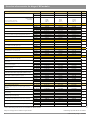
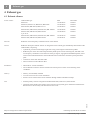
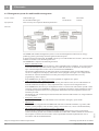
Overview of accessories for natural gas CHP modules
incl. 1) Set of elastic connections,
incl. 2) Calibrated electricity meter
EM-18/36*
EM-50/81*
ESS / internal
700-02-0020
700-02-0050
700-02-0070
700-02-0140
Art. no.
74 111 44
74 111 46
74 111 48
74 111 51
50 kW
81 kW
145 kW
with 1-2
70 kW
115 kW
204 kW
with 1-2
140 kW
207 kW
384 kW
with 1-2
Electrical output
Thermal output
Fuel usage
18 kW
36 kW
56 kW
with 1-2
2. Transport + installation
2.2.1 Lifting eyes (unloading in export destinations)
2.2.2 Additional transport brackets for horizontal transportation
2.2.3 Delivery in sections
2.3.1 Silencer hood and temperature-dependent extract fan
2.3.2 Plinth
EM-18/36
ESS / internal
3.2 Natural gas knocking monitoring
4.1. Exhaust silencer DD, pack 2 pce
EM-70/115
EM-140/207
9
710-00-0061
710-00-0061
10
74 392 50
74 392 50
74 392 50
710-00-0041
710-00-0042
Art. no.
74 177 53
74 177 53
74 177 54
ESS / internal
900-00-0101
900-00-0101
900-00-0102
Art. no.
70 007 81
70 007 81
70 007 82
ESS / internal
standard
standard
standard
standard
Art. no.
equipment level
equipment level
equipment level
equipment level
ESS / internal
710-00-0063
710-00-0063
710-00-0063
710-00-0064
Art. no.
74 392 51
EM-18/36
74 392 51
EM-50/81
74 392 51
EM-70/115
74 392 52
EM-140/207
ESS / internal
710-00-0052
710-00-0052
710-00-0052
standard
Art. no.
74 111 68
Art. no.
11
12
13
14
15
15
74 111 68
74 111 68
equipment level
710-00-0050
710-00-0050
710-00-0050
74 177 55
EM-70/115
74 177 55
EM-140/207
16
16
EM-18/36
74 177 55
EM-50/81
ESS / internal
710-00-0065
710-00-0066
710-00-0066
710-00-0067
Art. no.
74 392 53
74 392 54
74 392 54
74 392 55
ESS / internal
15
16
Art. no.
5. Heating
5.1 Higher heating water return temperatures 90/75 °C
EM-50/81
710-00-0041
ESS / internal
Page
710-00-0061
Art. no.
4. Exhaust gas
4.1. Exhaust silencer DD
EM-140/207*
ESS / internal
3. Gas
3.1 Gas tightness test
EM-70/115*
EM-50/81
EM-70/115
EM-140/207
18
ESS / internal
EM-18/36
710-00-0035
710-00-0035
710-00-0036
Art. no.
74 177 49
EM-50/81
75 177 49
EM-70/115
74 177 50
EM-140/207
18
20
710-00-0046
710-00-0046
710-00-0047
20
6. Ventilation
EM-18/36
6.1 Ventilation air via silencer hood
ESS / internal
Art. no.
74 111 94
74 111 94
74 111 95
6.2 (Extract) fan box on silencer hood
ESS / internal
710-00-0048
710-00-0048
710-00-0049
Art. no.
74 111 96
74 111 96
74 111 97
6.3 Recirculating air damper
(on request factory-fitted to fan box)
ESS / internal
710-00-0030
710-00-0031
710-00-0031
710-00-0032
Art. no.
74 111 75
EM-18/36
74 111 76
EM-50/81
74 111 76
EM-70/115
74 111 77
EM-140/207
7.1 Data BUS systems / interface (gateway)* (either LON BUS, MOD BUS,
CanOpen Bus or ProfiBus DP)
ESS / internal
710-00-0054
710-00-0054
710-00-0054
710-00-0054
Art. no.
74 112 01
74 112 01
74 112 01
74 112 01
7.2.1 Equipment level for operation to VDE 0108
ESS / internal
710-00-0055
710-00-0055
710-00-0055
Art. no.
74 111 79
74 111 79
74 111 79
710-00-0057
7. Electronics
20
21
24
24
24
ESS / internal
710-00-0057
710-00-0057
710-00-0057
Art. no.
74 112 04
74 112 04
74 112 04
74 112 04
ESS / internal
710-00-0021
710-00-0021
710-00-0021
710-00-0021
Art. no.
74 111 90
74 111 90
74 111 90
74 111 90
ESS / internal
710-00-0022
710-00-0022
710-00-0022
710-00-0022
Art. no.
74 111 87
74 111 87
74 111 87
74 111 87
ESS / internal
710-00-0023
710-00-0023
710-00-0023
710-00-0023
Art. no.
74 111 89
74 111 89
74 111 89
74 111 89
ESS / internal
710-00-0059
710-00-0059
710-00-0059
710-00-0059
Art. no.
74 177 56
74 177 56
74 177 56
74 177 56
7.4 Management system for multi-module management MMM Basis*
(additional options on request)
ESS / internal
710-00-0020
710-00-0020
710-00-0020
710-00-0020
Art. no.
74 111 85
74 111 85
74 111 85
74 111 85
7.5.1 Cylinder level control unit SFR*
ESS / internal
710-00-0060
710-00-0060
710-00-0060
710-00-0060
Art. no.
74 245 55
74 245 55
74 245 55
74 245 55
7.5.2 Load controller for 1 module*
ESS / internal
710-00-0053
710-00-0053
710-00-0053
Art. no.
EM-18/36
74 112 05
EM-50/81
74 112 05
EM-70/115
74 112 05
EM-140/207
35
900-00-0003
35
7.2.2 Uninterruptible reverse synchronisation after emergency power mode
7.3.1 Telecontrol LIGHT for single module systems* (not released for export!)
7.3.2 Telecontrol CLASSIC for single module systems* (for export on request!)
7.3.3 Telecontrol EXCLUSIVE* (for export on request!)
7.3.4 Telecontrol GPRS for single module systems* (customer mobile phone
contract + annual server charges) (not released for export!)
8. Service + training
8.1.1 Commissioning (Germany)
(in other countries, subject to costs incurred plus travelling expenses)
ESS / internal
900-00-0003
900-00-0003
900-00-0003
Art. no.
74 277 68
74 277 68
74 277 68
74 277 68
8.1.2 Lubricant TANK initial fill
ESS / internal
710-00-0007
710-00-0010
710-00-0010
710-00-0010
Art. no.
70 000 71
70 000 72
70 000 72
70 000 72
ESS / internal
900-00-0011
900-00-0011
900-00-0011
900-00-0011
Art. no.
70 007 62
70 007 62
70 007 62
70 007 62
ESS / internal
900-00-0100
900-00-0100
900-00-0100
900-00-0100
Art. no.
70 007 80
70 007 80
70 007 80
70 007 80
ESS / internal
900-00-0010
900-00-0010
900-00-0010
900-00-0010
Art. no.
70 007 79
70 007 79
70 007 79
70 007 79
ESS / internal
900-00-0006
900-00-0006
900-00-0006
900-00-0006
Art. no.
70 007 59
70 007 59
70 007 59
70 007 59
ESS / internal
900-00-0007
900-00-0007
900-00-0007
900-00-0007
Art. no.
70 007 76
70 007 76
70 007 76
70 007 76
8.1.3 Additional 8 h supervised test run in conjunction with commissioning
8.1.4 Order processing support for installation inspection in Germany
8.1.5 Warranty preservation after 4 weeks each (in Germany)
8.2.1 Local operating instructions, plus travel expenses
8.2.2 Operating instructions at manufacturing site
(per participant)
25
26
27
28
29
30
33
34
36
37
37
37
38
38
* More detailed specifications are available for these articles.
Subject to changes due to technical improvements 4
ESS Energie Systeme & Service GmbH
CHP accessory range – 01/2010
5368 463
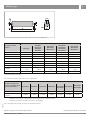
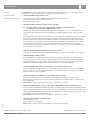
CHP compact module VITOBLOC 200
Overview of accessories for natural gas CHP modules
CHP compact module VITOBLOC 200
EM-199/263*
ESS / internal
Art. no.
incl. 1) Set of elastic connections,
incl. 2) Calibrated electricity meter
Electrical output
Thermal output
Fuel usage
2. Transport + installation
2.2.1 Lifting eyes (unloading in export destinations)
ESS / internal
Art. no.
2.2.2 Additional transport brackets for horizontal transportation
ESS / internal
Art. no.
2.2.3 Delivery in sections
ESS / internal
Art. no.
2.3.1 Silencer hood and temperature-dependent extract fan
ESS / internal
Art. no.
2.3.2 Plinth
ESS / internal
Art. no.
3. Gas
3.1 Gas tightness test
ESS / internal
Art. no.
3.2 Natural gas knocking monitoring
ESS / internal
Art. no.
EM-238/363*
EM-363/498*
EM-401/549*
700-02-0200
700-02-4080
700-02-4050
74 111 53
74 111 55
74 111 52
74 243 98
74 243 99
199 kW
263+20 kW
538 kW
with 1-2
199 kW
293 kW
553 kW
with 1-2
238 kW
363 kW
667 kW
with 1-2
363 kW
498 kW
960 kW
with 1-2
401 kW
549+26 kW
1053 kW
with 1-2
EM-199/263
EM-199/293
EM-238/363
EM-363/498
EM-401/549
9
710-00-0062
74 177 48
710-00-0062
74 177 48
710-00-0062
74 177 48
710-00-0062
74 177 48
710-00-0062
74 177 48
10
11
12
710-00-0080
74 392 92
710-00-0080
74 392 92
710-00-0080
74 392 92
710-00-0081
74 392 93
710-00-0081
74 392 93
EM-199/263
EM-199/293
EM-238/363
EM-363/498
EM-401/549
standard
standard
standard
standard
equipment level
equipment level
equipment level
equipment level
equipment level
EM-363/498
EM-401/549
16
16
4.1. Exhaust silencer DD
ESS / internal
Art. no.
710-00-0068
74 392 56
710-00-0068
74 392 56
710-00-0068
74 392 56
710-00-0069
74 392 57
710-00-0069
74 392 57
4.1. Exhaust silencer DD, pack 2 pce
ESS / internal
Art. no.
710-00-0070
74 392 58
EM-199/263
710-00-0070
74 392 58
EM-199/293
710-00-0070
74 392 58
EM-238/363
710-00-0071
74 392 59
EM-363/498
710-00-0071
74 392 59
EM-401/549
EM-199/263
EM-199/293
710-00-0037
74 177 51
EM-238/363
EM-363/498
EM-401/549
as standard
as standard
as standard
as standard
prepared
prepared
prepared
prepared
ESS / internal
Art. no.
6. Ventilation
6.1 Ventilation air via silencer hood
ESS / internal
Art. no.
6.2 (Extract) fan box on silencer hood
ESS / internal
Art. no.
6.3 Recirculating air damper
(on request factory-fitted to fan box)
ESS / internal
Art. no.
7. Electronics
15
standard
EM-199/293
5.1 Higher heating water return temperatures 90/75 °C
13
14
EM-199/263
5. Heating
Page
700-02-1980
710-00-0051
74 111 69
EM-238/363
4. Exhaust gas
15
15
16
18
18
20
20
20
710-00-0033
74 111 78
EM-199/263
710-00-0033
74 111 78
EM-199/293
710-00-0033
74 111 78
EM-238/363
710-00-0033
74 111 78
EM-363/498
710-00-0033
74 111 78
EM-401/549
710-00-0054
74 112 01
710-00-0054
74 112 01
710-00-0054
74 112 01
710-00-0054
74 112 01
710-00-0054
74 112 01
21
24
7.1 Data BUS systems / interface (gateway)* (either LON BUS, MOD
BUS, CanOpen Bus or ProfiBus DP)
ESS / internal
Art. no.
7.2.1 Equipment level for operation to VDE 0108
ESS / internal
Art. no.
7.2.2 Uninterruptible reverse synchronisation after emergency power
mode
ESS / internal
Art. no.
710-00-0057
74 112 04
710-00-0057
74 112 04
710-00-0057
74 112 04
710-00-0057
74 112 04
710-00-0057
74 112 04
25
7.3.1 Telecontrol LIGHT for single module systems*
(not released for export!)
ESS / internal
Art. no.
710-00-0021
74 111 90
710-00-0021
74 111 90
710-00-0021
74 111 90
710-00-0021
74 111 90
710-00-0021
74 111 90
26
7.3.2 Telecontrol CLASSIC for single module systems*
(for export on request!)
ESS / internal
Art. no.
710-00-0022
74 111 87
710-00-0022
74 111 87
710-00-0022
74 111 87
710-00-0022
74 111 87
710-00-0022
74 111 87
27
7.3.3 Telecontrol EXCLUSIVE* (for export on request!)
ESS / internal
Art. no.
710-00-0023
74 111 89
710-00-0023
74 111 89
710-00-0023
74 111 89
710-00-0023
74 111 89
710-00-0023
74 111 89
28
ESS / internal
Art. no.
ESS / internal
Art. no.
710-00-0059
74 177 56
710-00-0020
74 111 85
710-00-0059
74 177 56
710-00-0020
74 111 85
710-00-0059
74 177 56
710-00-0020
74 111 85
710-00-0059
74 177 56
710-00-0020
74 111 85
710-00-0059
74 177 56
710-00-0020
74 111 85
7.5.1 Cylinder level control unit SFR*
ESS / internal
Art. no.
710-00-0060
74 245 55
710-00-0060
74 245 55
710-00-0060
74 245 55
710-00-0060
74 245 55
710-00-0060
74 245 55
7.5.2 Load controller for 1 module*
ESS / internal
Art. no.
710-00-0053
74 112 05
EM-199/263
710-00-0053
74 112 05
EM-199/293
710-00-0053
74 112 05
EM-238/363
710-00-0053
74 112 05
EM-363/498
710-00-0053
74 112 05
EM-401/549
8.1.1 Commissioning (Germany)
(in other countries, subject to costs incurred plus travelling expenses)
ESS / internal
Art. no.
900-00-0004
74 277 69
900-00-0004
74 277 69
900-00-0004
74 277 69
900-00-0004
74 277 69
900-00-0004
74 277 69
35
8.1.2 Lubricant TANK initial fill
ESS / internal
Art. no.
710-00-0011
70 000 73
710-00-0011
70 000 73
710-00-0012
70 000 74
710-00-0011
70 000 73
710-00-0011
70 000 73
36
8.1.3 Additional 8 h supervised test run in conjunction with
commissioning
ESS / internal
Art. no.
900-00-0011
70 007 62
900-00-0011
70 007 62
900-00-0011
70 007 62
900-00-0011
70 007 62
900-00-0011
70 007 62
37
8.1.4 Order processing support
Installation inspection in Germany
ESS / internal
Art. no.
900-00-0100
70 007 80
900-00-0100
70 007 80
900-00-0100
70 007 80
900-00-0100
70 007 80
900-00-0100
70 007 80
37
8.1.5 Warranty preservation after 4 weeks each (in Germany)
ESS / internal
Art. no.
900-00-0010
70 007 79
900-00-0010
70 007 79
900-00-0010
70 007 79
900-00-0010
70 007 79
900-00-0010
70 007 79
37
8.2.1 Local operating instructions, plus travel expenses
ESS / internal
Art. no.
900-00-0006
70 007 59
900-00-0006
70 007 59
900-00-0006
70 007 59
900-00-0006
70 007 59
900-00-0006
70 007 59
38
8.2.2 Operating instructions at manufacturing site (per participant)
ESS / internal
Art. no.
900-00-0007
70 007 76
900-00-0007
70 007 76
900-00-0007
70 007 76
900-00-0007
70 007 76
900-00-0007
70 007 76
38
7.3.4 Telecontrol GPRS for single module systems* (customer mobile
phone contract + annual server charges) (not released for export!)
7.4 Management system for multi-module management MMM Basis*
(additional options on request)
8. Service + training
5368 463
EM-199/293*
700-02-1950
710-00-0056
74 111 80
24
24
29
30
33
34
35
* More detailed specifications are available for these articles.
Subject to changes due to technical improvements
CHP accessory range – 01/2010 ESS Energie Systeme & Service GmbH
5
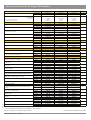
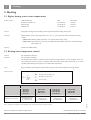
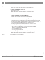
Overview of accessories for biogas CHP modules
ESS / internal
Art. no.
incl. 1) Set of elastic connections,
incl. 2) Calibrated electricity meter
Electrical output
Thermal output
Fuel usage
2. Transport + installation
2.2.1 Lifting eyes (unloading in export destinations)
2.2.2 Additional transport brackets for horizontal transportation
2.2.3 Delivery in sections
2.3.1 Silencer hood and temperature-dependent extract fan
2.3.2 Plinth
4.1. Exhaust silencer DD, pack 2 pce
BM-55/88*
BM-98/150*
700-02-0045
700-02-0065
700-02-0105
74 111 45
74 111 47
74 111 49
36 kW
66 kW
122 kW
with 1-2
55 kW
88 kW
165 kW
with 1-2
98 kW
150 kW
291 kW
with 1-2
BM-36/66
BM-55/88
BM-98/150
9
710-00-0061
74 392 50
710-00-0042
74 177 54
900-00-0102
70 007 82
standard
equipment level
710-00-0064
74 392 52
10
710-00-0061
74 392 50
710-00-0041
74 177 53
900-00-0101
70 007 81
standard
equipment level
710-00-0063
74 392 51
Page
ESS / internal
Art. no.
ESS / internal
Art. no.
ESS / internal
Art. no.
ESS / internal
Art. no.
ESS / internal
Art. no.
710-00-0061
74 392 50
710-00-0041
74 177 53
900-00-0101
70 007 81
standard
equipment level
710-00-0063
74 392 51
BM-36/66
BM-55/88
BM-98/150
16
ESS / internal
Art. no.
710-00-0066
74 392 54
710-00-0066
74 392 54
710-00-0067
74 392 55
16
4. Exhaust gas
4.1. Exhaust silencer DD
BM-36/66*
ESS / internal
12
13
14
16
Art. no.
6. Ventilation
11
BM-36/66
BM-55/88
BM-98/150
20
ESS / internal
Art. no.
ESS / internal
Art. no.
710-00-0046
74 111 94
710-00-0048
74 111 96
710-00-0046
74 111 94
710-00-0048
74 111 96
710-00-0047
74 111 95
710-00-0049
74 111 97
20
BM-36/66
BM-55/88
BM-98/150
24
ESS / internal
Art. no.
ESS / internal
Art. no.
710-00-0054
74 112 01
710-00-0057
74 112 04
710-00-0054
74 112 01
710-00-0057
74 112 04
710-00-0054
74 112 01
710-00-0057
74 112 04
ESS / internal
Art. no.
ESS / internal
Art. no.
ESS / internal
Art. no.
ESS / internal
Art. no.
ESS / internal
Art. no.
ESS / internal
Art. no.
ESS / internal
Art. no.
710-00-0021
74 111 90
710-00-0022
74 111 87
710-00-0023
74 111 89
710-00-0059
74 177 56
710-00-0020
74 111 85
710-00-0060
74 245 55
710-00-0053
74 112 05
710-00-0021
74 111 90
710-00-0022
74 111 87
710-00-0023
74 111 89
710-00-0059
74 177 56
710-00-0020
74 111 85
710-00-0060
74 245 55
710-00-0053
74 112 05
710-00-0021
74 111 90
710-00-0022
74 111 87
710-00-0023
74 111 89
710-00-0059
74 177 56
710-00-0020
74 111 85
710-00-0060
74 245 55
710-00-0053
74 112 05
BM-36/66
BM-55/88
BM-98/150
ESS / internal
900-00-0005
900-00-0005
900-00-0005
70 007 63
70 007 63
70 007 63
8.1.3 Additional 8 h supervised test run in conjunction with
commissioning
ESS / internal
Art. no.
ESS / internal
Art. no.
710-00-0009
70 000 75
900-00-0011
70 007 62
710-00-0009
70 000 75
900-00-0011
70 007 62
710-00-0009
70 000 75
900-00-0011
70 007 62
8.1.4 Order processing support
Installation inspection in Germany
ESS / internal
Art. no.
900-00-0100
70 007 80
900-00-0100
70 007 80
900-00-0100
70 007 80
ESS / internal
Art. no.
ESS / internal
8.2.1 Local operating instructions, plus travel expenses
Art. no.
ESS / internal
8.2.2 Operating instructions at manufacturing site (per participant)
Art. no.
900-00-0010
70 007 79
900-00-0006
70 007 59
900-00-0007
70 007 76
900-00-0010
70 007 79
900-00-0006
70 007 59
900-00-0007
70 007 76
900-00-0010
70 007 79
900-00-0006
70 007 59
900-00-0007
70 007 76
6.1 Ventilation air via silencer hood
6.2 (Extract) fan box on silencer hood
7. Electronics
7.1 Data BUS systems / interface (gateway)* (either LON BUS,
MOD BUS, CanOpen Bus or ProfiBus DP)
7.2.2 Uninterruptible reverse synchronisation after emergency
power mode
7.3.1 Telecontrol LIGHT for single module systems*
(not released for export!)
7.3.2 Telecontrol CLASSIC for single module systems* (for
export on request!)
7.3.3 Telecontrol EXCLUSIVE* (for export on request!)
7.3.4 Telecontrol GPRS for single module systems* (customer
mobile phone contract + annual server charges) (not released for export!)
7.4 Management system for multi-module management
MMM Basis* (additional options on request)
7.5.1 Cylinder level control unit SFR*
7.5.2 Load controller for 1 module*
8. Service + training
8.1.1 Commissioning (Germany)
(in other countries, subject to costs incurred plus travelling
expenses)
8.1.2 Lubricant TANK initial fill
Art. no.
8.1.5 Warranty preservation after 4 weeks each (in Germany)
20
24
25
26
27
28
29
30
33
34
35
35
36
37
37
37
38
38
* More detailed specifications are available for these articles.
Subject to changes due to technical improvements 6
ESS Energie Systeme & Service GmbH
CHP accessory range – 01/2010
5368 463
CHP compact module VITOBLOC 200
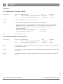
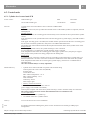
Overview of accessories for biogas CHP modules
CHP compact module VITOBLOC 200
ESS / internal
Art. no.
incl. 1) Set of elastic connections,
incl. 2) Calibrated electricity meter
Electrical output
Thermal output
Fuel usage
2. Transport + installation
2.2.1 Lifting eyes (unloading in export destinations)
2.2.2 Additional transport brackets for horizontal transportation
2.2.3 Delivery in sections
2.3.1 Silencer hood and temperature-dependent extract fan
2.3.2 Plinth
4.1. Exhaust silencer DD, pack 2 pce
6.2 (Extract) fan box on silencer hood
700-02-4055
74 111 50
74 111 54
74 392 62
123 kW
177 kW
343 kW
with 1-2
190 kW
238+16 kW
493 kW
with 1-2
366 kW
437+16 kW
960 kW
with 1-2
BM-190/238
BM-366/437
9
710-00-0062
74 177 48
710-00-0062
74 177 48
10
ESS / internal
710-00-0042
Art. no.
ESS / internal
Art. no.
ESS / internal
Art. no.
ESS / internal
Art. no.
ESS / internal
Art. no.
11
74 177 54
900-00-0102
12
70 007 82
standard
equipment level
710-00-0080
74 392 92
710-00-0081
74 392 93
710-00-0064
BM-123/177
BM-190/238
BM-366/437
16
710-00-0067
74 392 55
710-00-0068
74 392 56
710-00-0069
74 392 57
16
710-00-0070
710-00-0071
74 392 58
74 392 59
ESS / internal
Art. no.
BM-123/177
BM-190/238
BM-366/437
20
710-00-0047
74 111 95
as standard
prepared
as standard
prepared
20
ESS / internal
710-00-0049
Art. no.
20
74 111 97
BM-123/177
BM-190/238
BM-366/437
710-00-0054
74 112 01
710-00-0057
74 112 04
710-00-0054
74 112 01
710-00-0057
74 112 04
7.3.1 Telecontrol LIGHT for single module systems* (not released ESS / internal
for export!)
Art. no.
ESS / internal
7.3.2 Telecontrol CLASSIC for single module systems* (for
export on request!)
Art. no.
ESS / internal
7.3.3 Telecontrol EXCLUSIVE* (for export on request!)
Art. no.
ESS / internal
7.3.4 Telecontrol GPRS for single module systems* (customer
mobile phone contract + annual server charges) (not released for export!)
Art. no.
ESS / internal
7.4 Management system for multi-module management
MMM Basis* (additional options on request)
Art. no.
ESS / internal
7.5.1 Cylinder level control unit SFR*
Art. no.
ESS / internal
7.5.2 Load controller for 1 module*
Art. no.
710-00-0021
74 111 90
710-00-0022
74 111 87
710-00-0023
74 111 89
710-00-0059
74 177 56
710-00-0020
74 111 85
710-00-0060
74 245 55
710-00-0053
74 112 05
710-00-0021
74 111 90
710-00-0022
74 111 87
710-00-0023
74 111 89
710-00-0059
74 177 56
710-00-0020
74 111 85
710-00-0060
74 245 55
710-00-0053
74 112 05
710-00-0021
74 111 90
710-00-0022
74 111 87
710-00-0023
74 111 89
710-00-0059
74 177 56
710-00-0020
74 111 85
710-00-0060
74 245 55
710-00-0053
74 112 05
7.2.2 Uninterruptible reverse synchronisation after emergency
power mode
BM-123/177
BM-190/238
BM-366/437
900-00-0005
900-00-0005
900-00-0005
70 007 63
70 007 63
70 007 63
ESS / internal
Art. no.
ESS / internal
Art. no.
710-00-0009
70 000 75
900-00-0011
70 007 62
710-00-0011
70 000 73
900-00-0011
70 007 62
710-00-0011
70 000 73
900-00-0011
70 007 62
ESS / internal
Art. no.
ESS / internal
8.1.5 Warranty preservation after 4 weeks each (in Germany)
Art. no.
ESS / internal
8.2.1 Local operating instructions, plus travel expenses
Art. no.
ESS / internal
8.2.2 Operating instructions at manufacturing site (per participant)
Art. no.
900-00-0100
70 007 80
900-00-0010
70 007 79
900-00-0006
70 007 59
900-00-0007
70 007 76
900-00-0100
70 007 80
900-00-0010
70 007 79
900-00-0006
70 007 59
900-00-0007
70 007 76
900-00-0100
70 007 80
900-00-0010
70 007 79
900-00-0006
70 007 59
900-00-0007
70 007 76
8. Service + training
8.1.1 Commissioning (Germany)
(in other countries, subject to costs incurred plus travelling
expenses)
ESS / internal
8.1.2 Lubricant TANK initial fill
8.1.3 Additional 8 h supervised test run in conjunction with
commissioning
16
ESS / internal
Art. no.
710-00-0054
74 112 01
710-00-0057
74 112 04
MOD BUS, CanOpen Bus or ProfiBus DP)
13
14
74 392 52
ESS / internal
Art. no.
ESS / internal
Art. no.
7.1 Data BUS systems / interface (gateway)* (either LON BUS,
Page
BM-123/177
7. Electronics
Art. no.
8.1.4 Order processing support for installation inspection in
Germany
5368 463
BM-366/437*
700-02-1955
710-00-0061
74 392 50
6. Ventilation
6.1 Ventilation air via silencer hood
BM-190/238*
700-02-0125
ESS / internal
Art. no.
4. Exhaust gas
4.1. Exhaust silencer DD
BM-123/177*
24
24
25
26
27
28
29
30
33
34
35
35
36
37
37
37
38
38
* More detailed specifications are available for these articles.
Subject to changes due to technical improvements
CHP accessory range – 01/2010 ESS Energie Systeme & Service GmbH
7
1
Introduction
1 Introduction
5368 463
NoteThis product range describes in detail all articles and services provided by ESS which are available
through Viessmann Werke GmbH & Co. KG.
In addition, extra details from the Viessmann catalogue are included.
Subject to changes due to technical improvements 8
ESS Energie Systeme & Service GmbH
CHP accessory range – 01/2010
Transport and installation
2
2 Transport and installation
2.1 Transport within Germany
Article number
CHP module type for all CHP module types Viessmann
0000962
5368 463
Scope of serviceDelivery and unloading
ESS generally delivers from the Landsberg am Lech factory.
Transport from Landsberg am Lech should be arranged separately with a forwarder.
In Germany, Viessmann Logistik is commissioned by Viessmann Deutschland GmbH. Their HGVs are
equipped with lifting eyes to unload CHP modules.
Subject to changes due to technical improvements
CHP accessory range – 01/2010 ESS Energie Systeme & Service GmbH
9
2
Transport and installation
2.2 Handling
2.2.1 Lifting eyes (unloading in export destinations)
Article number CHP module type
EM-50/81, EM-70/115, EM 140/207,
BM-36/66, BM-55/88, BM-98/150, BM-123/177
EM-199/263, EM-199/293, EM-238/363,
EM-363/498, EM-401/549, BM-190/238, BM-366/437
Function
• For unloading and handling with a crane
ESS 710-00-0061
Viessmann
7439250
710-00-0062
7417748
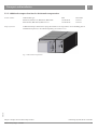
Fig. 1 Transport of a CHP module with a crane using lifting eyes
• 4 lifting eyes and 1 key per set
• Lifting eyes are attached to the exhaust outlet flange with cable ties
Note
• In Germany, the HGVs belonging to Viessmann Logistik are equipped with lifting eyes for unloading.
•Lifting eyes can be supplied free of charge with CHP module EM-18/36 if required. Please state when
ordering!
5368 463
Delivery Subject to changes due to technical improvements 10
ESS Energie Systeme & Service GmbH
CHP accessory range – 01/2010
Transport and installation
2
2.2.2 Additional transport brackets for horizontal transportation
Article number
CHP module type
EM-50/81, EM-70/115, BM-36/66, BM-55/88
EM-140/207, BM-98/150, BM-123/177
Scope of service
Additional transport brackets for laying the module on its long side for on-site handling plus an
installation inspection, to be ordered separately (see section 8.1.3)
ESS
710-00-0041 710-00-0042 Viessmann
7417753
7417754
5368 463
Fig. 2 Horizontal transportation
Subject to changes due to technical improvements
CHP accessory range – 01/2010 ESS Energie Systeme & Service GmbH
11
2
Transport and installation
2.2.3 Delivery in sections
Article number CHP module type
EM-50/81, EM-70/115, BM-36/66, BM-55/88 EM-140/207, BM-98/150, BM-123/177 Function The conditions at the installation location may make it necessary to handle the CHP module in sections.
If so, it is delivered in two sections:
1. Engine generator unit
2. Heat exchanger unit
ESS 900-00-0101 900-00-0102 Engine generator unit
Sectional
delivery
CHP module
Weight
in t
Viessmann
7000781
7000782
Heat exchanger unit
Weight
in t
Dimensions (L x W x H)
in mm
Dimensions (L x W x H)
in mm
EM-50/81
EM-70/115
BM-55/88
approx. 1.0
2000 x 800 x 1000
approx. 1.1
3000 x 900 x 1100
EM-140/207
BM-98/150
BM-123/177
approx. 1.5
2400 x 800 x 1200
approx. 2.1
3700 x 950 x 1200
Tab. 1 Sectional delivery of CHP module – dimensions and weights
Scope of service
The service provided is divided into the following three steps:
1. Dismantling the prepared CHP module at the ESS factory.
2.As a final step in the handling to be completed on site, the engine generator unit is positioned on the
heat exchanger unit (adjusted accordingly) and secured. Suitable lifting gear (e.g. assembly crane,
lifting pallet truck) for this purpose should be provided on site.
For this step, at least 2 other people (e.g. from the transport staff) should be available to assist at no
extra cost.
3.Re-assembling the prepared CHP module at the ESS factory.
Travel expenses and overnight accommodation for the 2 installers assigned to the job are included.
• Additional costs incurred for the extra transport load floor
• Overall transportation
• All lifting gear required
•Additional costs that we incur through unavoidable delays during handling or re-assembling the
CHP module
5368 463
On-site tasks / requirements
Subject to changes due to technical improvements 12
ESS Energie Systeme & Service GmbH
CHP accessory range – 01/2010
Transport and installation
2
2.3 Installation
2.3.1 Silencer hood and temperature-dependent fan
Article number
CHP module type
EM-199/263, EM-199/293, BM-190/238, EM-238/363 EM-363/498, EM-401/549, BM-366/437 Function If installed in areas where noise emissions are critical, the CHP module can be equipped with a ventilated
silencer hood, consisting of the silencer hood for the engine generator unit and the casing of the heat
exchanger unit.
Version •Sound insulation elements made of sheet steel, lined with combination elements made from bitumen
board and highly absorbent flexible foam with additional surface coating; area in contact with hot parts
lined with compound foam (300 kg/m3) with additional aluminium lining.
• The 25 μm thin coating is largely resistant to petrol and motor oil splashes and easy to clean.
• The surface coating protects against mechanical damage and has outstanding ageing resistance.
• Fire characteristics in accordance with FMVSS 302 and DIN 75200.
• In the hot area, the insulation is made of mineral wool/glass fibre and a perforated plate cover.
• The silencer hood elements can be removed for maintenance.
•The support structure can be removed for modification work, in order to be able to work with lifting
gear without hindrance.
•Fresh air inlet through louvres integrated into the side silencer hood casing. Combustion air inlet
through separate air inlet on the roof casing.
• 1 runtime-controlled extract fan.
•In addition, 1 temperature-dependent extract fan to supply the CHP module with sufficient combustion
air and cooling air at max. 500 Pa pressure for extract air duct.
• Average sound insulation of the hood approx. 20 dB.
• Flexible canvas flange to connect the downstream duct.
Delivery As loose accessories or mounted on the CHP module
Viessmann
7439292
7439293
5368 463
ESS 710-00-0080 710-00-0081 Subject to changes due to technical improvements
CHP accessory range – 01/2010 ESS Energie Systeme & Service GmbH
13
2
Transport and installation
2.3.2 Plinth
Article number CHP module type
EM-18/36, EM-50/81, EM-70/115,
BM-36/66, BM-55/88
EM 140/207, BM-98/150, BM-123/177 Function
Version
To mount the CHP module in a higher position (sufficient fresh air inlet from below) for on-site
integration of the exhaust condensate siphon loop/hydraulic seal
• Stainless steel channel section
• Length x width x height 1100 /1200 mm x 260 mm x 90 mm
Delivery As loose accessories
ESS Viessmann
710-00-0063
710-00-0064 7439251
7439252
2.3.3 Flexible feet
Article number on request
Function
With particularly critical foundations and wall bases (e.g. on gravel covers, ceilings with wooden joists),
air-filled damper elements can significantly attenuate structure-borne noise resulting from the effects of
resonance. The air dampers should be checked regularly on site for the correct filling pressure
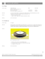
Version Fig. 3 Air-filled damper element
• Elastomer-metal connection with fitted floor plate
• Air chamber made from elastomer, reinforced with steel rings
• Air supply via car tyre valve
Delivery
As loose accessories
5368 463
Subject to changes due to technical improvements 14
ESS Energie Systeme & Service GmbH
CHP accessory range – 01/2010
3
Gas
3 Gas
3.1 Gas tightness test
Article number
CHP module type
EM-18/36, EM-50/81, EM-70/115 Version Function Tightness tester, including installation in the gas train or module control panel
The gas tightness tester consists of a pressure and monitoring PCB for installation in the gas train of the
CHP module. It is suitable for gas trains with two safety valves and monitors the safety function of the
valves following shutdown. The tester establishes any unacceptable leak in any of the gas valves and
prevents the CHP module from starting up if there is a fault.
According to EN 746-2, a tightness test should be carried out from 1200 kW heating output and above. In
DIN 33831-2 it is recommended from 390 kW and above.
Delivery
ESS 710-00-0052 Viessmann
7411168
Integrated into the CHP gas train
3.2 Natural gas knocking monitoring equipment
Article number Version
CHP module type
EM-50/81, EM-70/115, EM-140/207 EM-238/363
Function
If the methane count of the fuel gas (not to be confused with the methane content!) is below the
permissible level for the engine, after successful ignition the thermodynamic properties of the gas will
cause an additional ignition of the air-gas mixture outside the standard combustion range. This results
in significantly faster combustion with several flame fronts. Where these flame fronts meet, powerful
pressure waves are created whose sound emissions are heard as knocking noises.
Knocking causes much greater wear and leads to engine damage; it should always be prevented.
For this purpose, the natural gas knocking monitoring equipment is provided, which reliably prevents
knocking sounds as part of the CHP module control. If knocking persists, the output will decrease. If this
measure is not successful either, the engine must be switched off.
Viessmann
7417755
7411169
• For natural gas with a methane count < 75
• With a methane count between 80 and 75, provide output reduction!
• Knocking control fitted in the module or module control panel
• For EM-50/81, EM-70/115, EM-140/207 in separate control panel
• For EM-238/363 integrated in the CHP module or module control panel
5368 463
Delivery
ESS 710-00-0050 710-00-0051 Subject to changes due to technical improvements
CHP accessory range – 01/2010 ESS Energie Systeme & Service GmbH
15
4
Exhaust gas
4 Exhaust gas
4.1 Exhaust silencer
Article number
CHP module type
EM-18/36
EM-50/81, EM-70/115, BM-36/66, BM-55/88 EM-140/207, BM-98/150, BM-123/177 EM-199/263, EM-199/293, EM-238/363, BM-190/238 EM-363/498, EM-401/549, BM-366/437 2 pce in set
EM-199/263, EM-199/293, EM-238/363, BM-190/238 EM-363/498, EM-401/549, BM-366/437 Function Reduction of low frequency combustion noise in the exhaust
Version
Reflection absorption exhaust silencer for integration in the exhaust pipe immediately downstream of the
CHP module, comprising:
• Cylindrical, pressure-tested and gas-tight steel casing, with integral reinforcement profiles
•Reflection part on the inlet side and permanently fixed special circular silencing link, matched to the
low frequency combustion noise emissions of the gas engine, segregated with bulkhead panels, lined
with moisture-stabilised stainless steel needle felt and covered with 2 mm thick special perforated
plate.
• Connectors on the inlet and outlet sides
• Drain connection in the reflection floor
ESS 710-00-0065 710-00-0066 710-00-0067 710-00-0068 710-00-0069 Viessmann
7439253
7439254
7439255
7439256
7439257
710-00-0070 710-00-0071 7439258
7439259
• Horizontal or vertical installation
•The condensate connector must be located at the lowest point to ensure correct draining of the
condensate.
Delivery
• Delivery not unloaded, insulated
• As loose accessories for on-site installation
• Ensure correct structure-borne noise insulation through suitable installation clamps!
Note
• Internal primary silencers integrated in modules EM-50/81, EM-70/115, EM-140/207.
•Upstream of the stainless steel silencer, there must not be any black pipe in mild steel installed in the
flow direction. The warranty will otherwise become void!
5368 463
Installation
Subject to changes due to technical improvements 16
ESS Energie Systeme & Service GmbH
CHP accessory range – 01/2010
4
Exhaust gas
Fig. 4 Dimensions and connections of the exhaust silencer for a CHP module
CHP module type
Secondary exhaust
silencer
EM-140/207
BM-98/150
BM-123/177
EM-199/263
EM-199/293
EM-238/363
BM-190/238
EM-363/498
EM-401/549
BM-366/437
L1
mm
1,500
2,000
2,200
2,000
2,400
L2 mm
1,300
1,800
2,000
2,000
2,200
Ø D1
mm
237
356
457
508
606
Ø D2
DN
50
80
125
150
200
Ø D3
DN
50
80
125
150
200
½”
½”
¾”
¾”
¾”
40
65
105
120
170
AKO1)
Weight
kg
Stainless steel
1.4571
Material
Pressure stage max.
1)
EM-18/36
EM-50/81
EM-70/115
BM-36/66
BM-55/88
Pa
Stainless steel
1.4571
5,000
5,000
Stainless steel
1.4571
Stainless steel
1.4571
5,000
Stainless steel
1.4571
5,000
5,000
Condensate drain connection
Tab. 2 Dimensions of the exhaust silencer for a CHP module
CHP module type
Exhaust sound pressure
level at 1 m distance in the
open to DIN 45635 1)
EM-18/36
EM-50/81
EM-70/115
EM-140/207
EM-199/263
EM-199/293
EM-238/363
EM-363/437
EM-401/549
46
41
47
57
75
72
74
< 2 mbar
< 2 mbar
< 2 mbar
< 4 mbar
< 4 mbar
< 4 mbar
< 4 mbar
dB(A)
Exhaust pressure drop in
silencer
Tolerance to given levels 3 dB(A); relative to an exhaust silencer. Exhaust air noise
measured 1 m downstream of duct with silencer hood and fan
5368 463
1)
Tab. 3 Residual exhaust sound pressure level with exhaust silencer
Subject to changes due to technical improvements
CHP accessory range – 01/2010 ESS Energie Systeme & Service GmbH
17
5
Heating
5 Heating
5.1 Higher heating water return temperatures
Article number
CHP module type
EM-50/81, EM-70/115 EM-140/207
EM-238/363 Version Equipped with larger heat exchanger and if required matched cooling water pump
ESS 710-00-0035 710-00-0036 710-00-0037 Viessmann
7417749
7417750
7417751
Function Higher heating water return temperatures 90 / 75 °C, e.g. for operation with an absorption cooling
system
• Please note:Heating output reduced by 5 % with the same energy usage
• Please note:After inspection, there may be additional maintenance costs due to the thermal load
of the engine oil
Delivery
Fitted in the CHP module
5.2 Heating water temperature control
Version
See Viessmann catalogue
Function
See Viessmann catalogue
The Vitobloc 200 contains a controller with a continuous output signal 0..10 V as standard. Via an onsite mixing valve with servomotor, it regulates either the heating water return temperature or an on-site
variable speed heating water pump for a constant flow temperature.
Note
Biogas modules should always be fitted with a heating water return temperature raising facility!
Note for mixer
Valve flow rate at 100 % lift
Heating water flow rate
Pressure drop
CHP module type
EM-50/81
EM-70/115
BM-36/66
BM-55/88
Three-way valve body
Internal diameter DN 40
threaded connection
with fitting PN 16
kVS value 25 m3/h
EM-199/263
EM-199/293
BM-190/238
EM-238/363
EM-149/207
BM-98/150
BM-123/177
Internal diameter DN 50
Flange PN 16
kVS value 40 m3/h
EM-363/498
EM-401/549
BM-366/437
Internal diameter DN 65
Flange PN 16
kVS value 63 m3/h
Internal diameter DN 80
Flange PN 16
kVS value 180 m3/h
Subject to changes due to technical improvements 18
5368 463
Tab. 4 Sizing the components in the heating water return temperature raising assembly
ESS Energie Systeme & Service GmbH
CHP accessory range – 01/2010
Heating
5
5.3 Heating water connection set
Version
See Viessmann catalogue
NoteTo complete the heating water connection set, the installation of a heating water pump is additionally
required. It should be sized on site to the required delivery head (and possibly delivery flow rate). (For a
recommendation for heating water pump sizing, see 0). If using a variable speed pump, an input signal of
0-10V is required if the return temperature raising facility is not used.
The shut-off valves for Vitobloc 200 EM-238/363, EM-363/498, EM-401/589 and BM-366/437 should be
ordered separately:
EM-238/363 2 shut-off valves DN 65
EM-363/498, EM-401/589, BM-366/437 2 shut-off valves DN 80
Viessmann article no. corresponding to CHP type
Heating water connection set
EM-18/36
Part no.
EM-50/81
EM-70/115
BM-36/66
BM-55/88
EM-149/207
BM-98/150
BM-123/177
EM-199/263
EM-199/293
BM-190/238
EM238/363
EM-363/498
EM-401/549
BM-366/437
Z007326
Z007327
Z007328
Z007328
Z007329
Z008582
Expansion vessel
9572214
9572214
9572212
9572212
9572215
9572904
Cap valve
9572213
9572213
9572213
9572213
9572213
9572213
Fitting block with pressure gauge
7188380
7188380
7188380
7188380
7188380
7188380
Retainer
9572216
9572216
―
―
―
―
Standard delivery
Safety valve
9572222
9572222
9572226
9572991
9572991
9572992
Thermometer
2 x 9034009
2 x 9034009
2 x 9034009
2 x 9034009
2 x 9034009
2 x 9034009
Shut-off valves
2 x 9572262
2 x 9572263
2 x 9572264
2 x 9572264
―
―
7143894
7143894
7143894
7143894
7143894
7143894
Drain
Tab. 1 Article numbers of components in the heating water connection set in the Viessmann catalogue
CHP module type
Module details
EM-18/36
EM-50/81
BM-36/66
EM-70/115
BM-55/88
EM-140/207
BM-98/150
BM-123/177
EM-199/263
EM-199/293
BM-190/238
EM-238/363
EM-363/498
EM-401/549
BM-366/437
Temperature delta in K
15
20
20
20
20
20
20
Flow rate in m³/h
2.1
3.5
4.9
8.9
12.6
23.5
15.6
DN 25
DN 40
DN 40
DN 50
DN 65
DN 65
DN 80
4
6
6
7
9
9
9
Grundfos
Grundfos
Grundfos
Grundfos
Grundfos
Grundfos
Grundfos
Magna 25-60
Magna 32-100
Magna 32-100
Magna 40-120
Magna 50-120
Magna 50-120 F
Magna 65-120 F
DN 25
DN 32
DN 32
DN 40 (32)
DN 50
DN 50
DN 65
Connection
Pressure drop in m*
Pump recommendation
Manufacturer
Type
Int. diameter
230
230
230
230
230
230
230
Delivery head range in m
Voltage in V
0.5..6
0.5..11.5
0.5..11.5
0.5..12.5
0.5..13
0.5..13
0.5..13
Flow rate range in m³/h
0..8.5
0..11.5
0..11.5
0..22.5
0..32
0..32
0..38
7.5
2
9.5
3
10.5
variable speed
12.0
variable speed
5368 463
Delivery head at CHP
nominal flow rate in m at
speed stage
only variable
speed
7.5
1
7.5
1
* Including plate heat exchanger, return temperature raising facility, heat meter, dirt trap, connectors, shut-off valves etc. (guide values)
Tab. 2 Recommendation for heating water pump sizing
Subject to changes due to technical improvements
CHP accessory range – 01/2010 ESS Energie Systeme & Service GmbH
19
5
Heating
Ventilation
5.4 Ventilation air via silencer hood
Article number Consec. posn CHP module type ESS 6.1.1
EM-50/81, EM-70/115, BM-36/66, BM-55/88 710-00-0046 6.1.2 EM-140/207, BM-98/150, BM-123/177 710-00-0047 Function • Separate supply of cooling air with raised flow rate
Viessmann
7411194
7411195
Version
• CHP module sealed against ingress of ambient air from within the plinth.
• For the ventilation air, a corresponding aperture is provided at the top of the module at the front.
• Please note: Subject to the length of the duct, a separate ventilation air fan may be required. The
permissible over- and underpressure within the silencer hood must not exceed 1 mbar
• Aperture dimensions
EM-50/81, EM-70/115, BM-36/66, BM-55/88 340 x 680 mm
EM-140/207, BM-98/150, BM-123/177 530 x 680 mm
Delivery
Fitted in the CHP module
5.5 (Extract) fan box on silencer hood
Article number
Consec. posn CHP module type ESS 6.2.1
EM-50/81, EM-70/115, BM-36/66, BM-55/88 710-00-0048 6.2.2 EM-140/207, BM-98/150, BM-123/177 710-00-0049 Function The conditions at the installation location may make it necessary to position the fan box on the top of the
CHP module silencer hood.
Version
For a fan mounted on the top of the silencer hood, an additional reinforcement and a new rear cover panel
are required.
Delivery
Installed in the CHP module, option for transportation as loose, fully wired accessories (if confirmed in
the order)
5368 463
Viessmann
7411196
7411197
Subject to changes due to technical improvements 20
ESS Energie Systeme & Service GmbH
CHP accessory range – 01/2010
Heating
5
5.6 Recirculating air damper
5.6.1 Recirculating air damper in profiled fitting for EM-18/36
Article number
Function CHP module type
ESS Viessmann
EM-18/36
710-00-0030 7411175
The recirculating air damper is used for room heating with warm extract air. On a controller, any
temperature from 10 to 35 °C can be set. Subject to room temperature, the damper servomotor constantly
opens or closes the louvre damper to regulate the set temperature.
Please note: In Germany, in accordance with the occupational safety directive, extract air must not be
routed into workrooms or other rooms people have access to!
Please note: If installed upstream of the optional extract air damper, machine/fan noise in the installation
room will be without attenuation!
Version
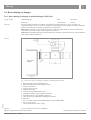
Fig. 5 Connection of the recirculating air damper to a CHP module EM-18/36
1 Branch 90° ID 315 mm, length 500 mm
2 Shut-off damper ID 315 mm, length 250 mm
3 Female connections
4 Fixing clamps 315 mm
5 Damper servomotor
6 Control unit with temperature sensor
7 Flanged collar ID 315 mm (module connection)
8 Plain flange ID 315 mm (module connection)
9 Hose ID 315 mm, length 500 mm (flexible connector)
10Hose clip
• Pos. 7, 8 and 9 are part of the standard delivery of the CHP module
• Pos. 4 and 10 on site
• On-site requirements: 230 V supply
5368 463
Delivery As loose accessories for on-site installation
Subject to changes due to technical improvements
CHP accessory range – 01/2010 ESS Energie Systeme & Service GmbH
21
5
Heating
5.6.2 Recirculating air damper for modules EM-50/81 and EM-70/115
Article number
CHP module type
EM-50/81, EM-70/115
ESS 710-00-0031 Viessmann
7411176
Function The recirculating air damper is used for room heating with warm extract air.
On a controller, any temperature from 10 to 35 °C can be set. Subject to room temperature, the damper
servomotor constantly opens or closes the louvre damper to regulate the set temperature.
Please note: In Germany, in accordance with the occupational safety directive, extract air must not be
routed into workrooms or other rooms people have access to!
Please note: If installed upstream of the optional extract air damper, machine/fan noise in the installation
room will be without attenuation!
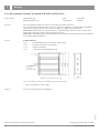
Version Standard delivery:
1 pce
Shut-off damper ID 370 x 370 mm, 120 mm deep
1 pce
Protective grille 370 x 370 mm P20
1 pce
Damper servomotor
1 pce
Control unit with temperature sensor
Abb. 6 Recirculating air damper for modules EM-50/81 and EM-70/115
• On-site requirements: 230 V supply
As loose accessories for on-site installation
5368 463
Delivery
Subject to changes due to technical improvements 22
ESS Energie Systeme & Service GmbH
CHP accessory range – 01/2010
Heating
5
5.6.3 Recirculating air damper for modules EM-140/207 to EM-401/549
Article number
Consec. posnCHP module type 6.3.3.1
EM-140/207 6.3.3.2
EM-199/263, EM-199/293, EM-238/363
EM-363/498, EM-401/549
ESS 710-00-0032 710-00-0033
Viessmann
7411177
7411178
FunctionThe recirculating air damper is used for room heating with warm extract air.
On a controller, any temperature from 10 to 35 °C can be set. Subject to room temperature, the damper
servomotor constantly opens or closes the louvre damper to regulate the set temperature.
Please note: In Germany, in accordance with the occupational safety directive, extract air must not be
routed into workrooms or other rooms people have access to!
Please note: If installed upstream of the optional extract air damper, machine/fan noise in the installation
room will be without attenuation!
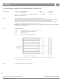
Standard delivery:
1 pce
Shut-off damper ID 545 x 545 mm, 110 mm deep
1 pce
Protective grille 545 x 545 mm P20
1 pce
Damper servomotor
1 pce
Control unit with temperature sensor
Fig. 7 Recirculating air damper for modules EM-140/207, EM-199/263, EM-199/293 and EM-238/363
• On-site requirements: 230 V supply
Delivery As loose accessories for on-site installation
5368 463
Version Subject to changes due to technical improvements
CHP accessory range – 01/2010 ESS Energie Systeme & Service GmbH
23
6
Electronics
6 Electronics
6.1 Data BUS systems / interfaces (gateway)
Article number
CHP module type
for all CHP module types Function
Computer connection according to requirements on site
Version
Plug-in module instead of RS232 with protocol 3964
Possible interfaces
•
•
•
•
•
•
Delivery
Fitted in the CHP module
ESS 710-00-0054 Viessmann
7411201
Gateway RK 512
Gateway ProfiBus DP slave connection
Gateway LON BUS connection
Gateway CANopen connection
Gateway MOD BUS connection
Gateway with DK3964 R multi-module systems
NoteAs part of order processing, the client should provide precise details about the protocol and data interface
to be set up.
6.2 Options for power failure
6.2.1 Equipment level to VDE 0108 for emergency power mode
Article number
CHP module type
EM-50/81, EM-70/115, EM-140/207 EM-238/363
ESS 710-00-0055 710-00-0056 Viessmann
7411179
7411180
Version Equipment level for operation to VDE 0108, comprising
• Batteries to VDE 0510 part 2
• Independent battery voltage monitor
• Key switch for test run
• Key switch for power failure simulation
• Incl. configuration expenditure
• Additional zero volt message contacts for parallel mains mode and emergency power mode
Note:
The standard emergency power mode (without equipment level to VDE 0108) is included in the Vitobloc
standard delivery.
Delivery
Fitted in the CHP module
Subject to changes due to technical improvements 24
ESS Energie Systeme & Service GmbH
CHP accessory range – 01/2010
5368 463
Function The module automatically recognises the power failure and disconnects from the mains.
After on-site load shedding of all consumers not eligible for emergency power, and opening of the on-site
mains coupling switch, the module can switch to emergency power. After restoration of the power supply
and a brief power steadying phase, the module is shut down and the on-site mains coupling switch is
closed. The module then runs according to standard mode.
As heat is still generated in emergency power mode, adequate provision must be made to transfer this
heat and, if necessary, supply a cooling system or buffer cylinder.
Electronics
6
6.2.2 Uninterruptible reverse synchronisation
5368 463
Article number
CHP module type
ESS Viessmann
All CHP module types 710-00-0057 7411204
Function After power is restored following a power failure and CHP emergency power mode stops, the module is
automatically resynchronised to the public grid, as long as the on-site mains isolator is able to perform
synchronisation.
Power failure
The mains isolator is open, the CHP module operates in isolated mode
Power supply restoration
After the mains stabilising time has expired, the synchroniser receives the "enabled for synchronising"
signal.
The synchroniser compares the actual "mains voltage" with the "generator voltage" or the "busbar
voltage" and regulates the CHP module speed via the "higher/lower" adjusting pulses.
If the voltage, frequency and phase angle differential are within the permissible limits, then the start pulse
to the mains isolator is issued.
After switching and feedback (mains isolator is ON), the CHP module automatically enters "parallel
mains mode".
Provide this control for every module; the load stages are managed on site.
The uninterruptible reverse synchronisation is commissioned and the safety interlocks within the modules
are disabled on site.
Additional option:
Uninterruptible emergency power supply when the machine is running with optimised load (consumer
load lower than module output) available on request; load stages are managed on site.
Standard delivery •In separate wall mounted casing
Control panel: 500 x 500 x 210 mm (H/W/D)
IP rating:
IP 41
Colour:
RAL 7035
Max. ambient temperature: 45 °C
Max. relative humidity: 70 %
VDE:
0660/500
Cable entry:
below
Door hinges:
on left
•With the following integral parts:
Fuse 24 VDC (power supply from module control field)
Fuse 400 V mains voltage
Fuse 400 V busbar voltage
Synchroniser SYN
Time relay
2 pce Fleeting relay
5 pce Control relay
Control panel complete with all necessary fuses and relays, wired to terminals ready for connection.
On-site requirements:
•Synchronising mains isolator with
- Motor storage drive 24 VDC
- Switch-on coil 24 VDC
- Trip coil 24 VDC
- Feedback contacts (actual ON / actual OFF)
• Mains test voltage output 400 V / 6 A upstream of mains isolator
•Sufficient cable (cross-section of the 24 VDC cables)
In case of problems such as
- large distances between the CHP and mains isolator
- high current drawn by the motor drive
- high currect drawn by the switch-on/trip coils
a separate on-site buffer voltage 24 VDC must be provided.
Delivery
As loose accessories for on-site installation
Subject to changes due to technical improvements
CHP accessory range – 01/2010 ESS Energie Systeme & Service GmbH
25
6
Electronics
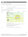
6.3 TeleControl remote monitoring
On-site requirementsAt least an analogue landline, no extension(!), as an option an ISDN connection as well; to be provided
on site.
Specification
This accessory has a separate detailed specification.
DeliveryAs loose accessories for on-site installation in a separate wall mounted casing; with module EM-238/363,
optional integration in the module
6.3.1 Telecontrol Light for single module systems
Article number
Function
CHP module type
for all CHP module types Fig. 8 Telecontrol Light function diagram
The Telecontrol Light is only used to view current live online data for the CHP module on the PC.
► There is no longer-term data recording for representation on graphs
► No fault messages can be sent as SMS, fax or email
► Only one module can be selected
Note
Due to varying telecommunications standards, only enabled for Germany!
Viessmann
7411190
5368 463
ESS 710-00-0021 Subject to changes due to technical improvements 26
ESS Energie Systeme & Service GmbH
CHP accessory range – 01/2010
Electronics
6
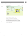
6.3.2 Telecontrol Light for single module systems
Article number
Function
CHP module type
for all CHP module types Fig. 9 Telecontrol Classic function diagram
In the Telecontrol Classic version, the following functions are available:
► Up to one CHP module can be selected
► Hourly, daily and annual rates can be shown on graphs
► The graphs are specified at the factory and cannot be changed
► Display of the current status of the system (online live data view)
► Transmission of fault and maintenance messages by fax, SMS or email
Note
Due to varying telecommunications standards, only enabled for Germany!
For other countries on request.
Viessmann
7411187
5368 463
ESS 710-00-0022 Subject to changes due to technical improvements
CHP accessory range – 01/2010 ESS Energie Systeme & Service GmbH
27
6
Electronics
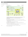
6.3.3 Telecontrol Exclusive
Article number Function
CHP module type
for all CHP module types Fig. 10 Telecontrol Exclusive function diagram
ESS 710-00-0023 Viessmann
7411189
The Exclusive version is required if a host is available in the system whose analogue values, fault
messages and operating messages are also recorded and could be depicted on graphs.
Functionality as per Telecontrol Top version with the following extensions:
► Recall function
► Can connect to the internet via DSL (DSL connection must be available in the CHP system)
► Data export to Excel or as ASCII file
►Additional digital and analogue input/output cards can be connected, for example to connect on-site
temperature sensors
► In addition, the following optional functions are possible:
► LON BUS connection to select the Telecontrol via a higher ranking management system
► M BUS to select up to three heat meters
►OPC-Server: if a visualisation is already available, module data can be read by the OPC server and
made availabe to the third party system for further processing
5368 463
NoteDue to varying telecommunications standards, only enabled for Germany!
For other countries on request.
Subject to changes due to technical improvements 28
ESS Energie Systeme & Service GmbH
CHP accessory range – 01/2010
Electronics
6
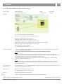
6.3.4 Telecontrol GPRS for single module systems
Article number
Function
CHP module type
for all CHP module types Fig. 11 Telecontrol GPRS function diagram
► Access to the recorded data via D1 mobile network
► Up to one CHP module can be selected
► Module data recording every minute for 1 year
► Additional recording of module data if status changes
► Message list with display of module values at the moment of status change
► Display of the recorded module values on a line graph
► Line graphs are freely adjustable
► Fault message transfer by email
ESS 710-00-0059 Viessmann
7417756
On-site requirementsFor every CHP module whose data must be made available, the following requirements are necessary:
1. Telecontrol GPRS modem hardware
2. Guaranteed reception of the D1 mobile network at the installation location!
Note:
Note the maximum cable lengths when selecting the installation location as well as the quality of
reception of the mobile network. As an aid to determining the area with the highest field strength around
the installation location, a mobile phone with a D1 card can be used.
3. D1 mobile phone card with tariff for GPRS data transmission with data flat rate, without volume
restriction and deactivated PIN scan
Note:
After the customer has purchased and enabled the D1 SIM card, the mobile phone card is checked
and configured together with the modem hardware by ESS. Perfect operation cannot be guaranteed in
different regional areas.
5368 463
Requirement for Written declaration of consent from the owner or CHP operator for external data transmission (as per the
commissioning German Federal Data Protection Act)
Operating costs ► Annual
Delivery
Integration in the module control panel
Note
Due to varying telecommunications standards, only enabled for Germany!
service charge €120 (from year 2)
► Setting up additional users, €200 per user
Subject to changes due to technical improvements
CHP accessory range – 01/2010 ESS Energie Systeme & Service GmbH
29
6
Electronics
6.4 Management system for multi-module management
CHP module type
for all CHP module types This accessory has a separate detailed specification.
Function
ESS 710-00-0020 Viessmann
7411185
MMM-Basis
Automatic mode
Manual mode
CHP module
Boiler
Boiler 1
Boiler
CHP module
DK3964R interface
Heating centre
Emergency power
with 1 module
Boiler 2
CHP module 1
heating base loadpower
with 1 module
Boiler 3
CHP module 2
heating base loadpower
with 1 module
The MMM multi-module management system is a universal management architecture for energyproducing systems, particularly those that generate heat and power.
In electrical mains parallel mode, the MMM controls up to 2 CHP modules and 3 boilers, where the CHP
modules are used to cover the heating base load.
The MMM-Basis comprises the following functions:
•Boiler in automatic mode
Boilers are selected and deselected subject to freely adjustable limits. In addition, every limit can have
a nominated PT100 temperature sensor, subject to which the selection or deselection will take place.
Up to 4 PT100 temperature sensors can be connected in the MMM-Basis.
The selection and deselection can take place subject to temperature, where corresponding heating
curves are configured via the display. The boilers can be equipped with single or two-stage burners.
The order for selection and deselection can take place subject to the boiler hours run or by
programming a boiler sequence.
In the MMM-Basis, the boiler output can be regulated via "higher/lower" pulses.
•CHP in automatic mode / heating base load
The CHP modules should primarily cover the heating base load. For this, the two CHP modules are
selected and deselected subject to freely adjustable limits. Any limit can be assigned a sensor.
In the MMM-Basis, there are up to 4 temperature sensors to choose from. This means cylinder control
is already possible in the MMM-Basis. However, it should be noted that to select and deselect boilers
(if installed), temperature sensors are a prerequisite and therefore not all 4 temperature sensors can
necessarily be used.
The boilers are only started subject to demand if the heat from the CHP module is no longer sufficient
to cover demand.
•Emergency power mode
In the MMM-Basis, up to one CHP module can be selected in emergency power mode.
•Manual level
A manual level is integrated into the MMM with which all connected assemblies (e.g. boiler, CHP
modules, system periphery such as boilers, pumps, control valves etc.) can be controlled manually.
•DK3964R interface for management system or Telecontrol
A serial interface enables the connection of a higher ranking management system or Telecontrol
remote monitoring by ESS. All available measured and control data is made available for transmission.
The computer connection for the transfer of the required data should be implemented on site in
accordance with the installed hardware.
Subject to changes due to technical improvements 30
ESS Energie Systeme & Service GmbH
CHP accessory range – 01/2010
5368 463
Article number
Specification
Electronics
6
Version The MMM-Basis can be supplied either installed in a wall mounted casing or on a mounting plate (for
installation in a separate control panel – not for the CHP control panel).
Optional versions
•OPTION MMM Control panel version
and functions (on request) For the installation of further MMM options, additional space is required:
Control panel 2000 x 800 x 600 mm with plinth
Power supply unit 24 VDC
• OPTION MMM Controller assembly with 4 controllers
E.g. for boiler return temperature raising facility / boiler low end temperature,
or heating circuit control unit / DHW heating system
Control valve regulation according to freely adjustable temperature or set value calculated from two
temperatures (flow temperature/outside temperature), including regulation of one pump per control
circuit.
For the controller assembly with 4 controllers, a total of 4 analogue and 8 digital outputs are available.
For example, the boiler return temperature raising facility thus ensures a freely adjustable internal
minimum boiler water temperature. In addition, a boiler low end temperature control can ensure that
the internal boiler water temperature does not fall below an adjustable "low end temperature" limit.
As a further possible application, with an auxiliary assembly up to four heating circuits can be
controlled subject to the outside temperature. Alternatively, a primary store system for DHW heating
can be controlled and regulated.
• OPTION MMM Modulating operation (for up to 2 boilers)
This optional controller assembly is required for modulating control via an analogue 0 - 10 V signal.
• OPTION MMM Cylinder control
In the MMM-Basis, 4 temperature sensors are already available. This means it is already possible
in the Basis version to achieve simple cylinder control. However, it may be that not all temperature
sensors can be used for cylinder control. If the 4 temperature sensors in the Basis are insufficient,
4 additional PT100 temperature sensors can be connected via an auxiliary assembly.
• OPTION MMM Control of the residual power to be drawn from the mains
In this operating mode, CHP modules are selected and deselected subject to an on-site residual mains
signal 0 - 10 V or 0 - 20 mA. The CHP modules are modulated between 50 % and 100 % in order to
use as little mains power as possible.
•OPTION MMM Load shedding for power failure (up to 16 stages)
If there is a power failure, up to 16 load stages can be enabled for emergency power mode.
Enabling these load stages ensures that no loads are hooked up to the CHP module or modules at an
unfavourable time.
Please note: a separate control panel extension is required for this option!
• OPTION MMM Emergency power mode with 2 CHP modules with active load distributor
If more than one CHP module should be selected in emergency power mode, the active load distributor
option is required. In emergency power mode, the active load distributor ensures even load distribution
to both CHP modules. The current transformers are installed in the optional link-up facility. The wiring
to the MMM panel should be installed on site.
Please note: a separate control panel extension is required for this option!
5368 463
• OPTION MMM Additional auxiliary drive
Fuse outlet 400 V / 16 A
(e.g. for boiler) incl. installation
Please note: a separate control panel extension is required for this option!
Subject to changes due to technical improvements
CHP accessory range – 01/2010 ESS Energie Systeme & Service GmbH
31
6
Electronics
Optional versions
• OPTION MMM Additional auxiliary drive
and functions Fuse outlet 230 V / 16 A (e.g. for boiler) incl. installation
Please note: a separate control panel extension is required for this option!
• OPTION MMM Additional auxiliary drive
Pump control up to 4 kW
Please note: a separate control panel extension is required for this option!
• OPTION MMM Databus connection LON BUS alternative
OPTION MMM Databus connection ProfiBus DP slave alternative
OPTION MMM Databus connection CANopen BUS alternative
OPTION MMM Databus connection MODBUS BUS
Computer connection in each case according to requirements on site
• OPTION MMM Remote monitoring / actual data capture with Telecontrol "Exclusive"
Remote monitoring and actual data capture takes place via an external appliance, the so-called
Telecontrol. The Telecontrol is connected to the MMM via a serial interface. Using the associated
visualisation software, it is possible to dial into the system remotely via the telephone network.
The Telecontrol is available in four different version (see separate Telecontrol Specification). To
connect the Telecontrol to the MMM, the "Exclusive" version is required.
The following functions are implemented in the "Exclusive" Telecontrol version:
-Sending messages if there is a fault (SMS, fax, email)
-These messages can be programmed to be allocated to certain people. For example, CHP faults can
be sent to different people than general boiler or system faults.
-Data recording of all CHP values and up to 16 analogue values from the MMM.
The data is depicted on freely configurable graphs.
- Long-term fault message history
- Long-term operating message history
- Establishing user profiles to save individual settings
-Once a user has registered with the Telecontrol and set up a graph according to their individual
criteria, the same graph can be viewed again on another PC without having to reconfigure it.
Please note: a separate control panel extension is required for this option!
As loose accessories for on-site installation
5368 463
Delivery
Subject to changes due to technical improvements 32
ESS Energie Systeme & Service GmbH
CHP accessory range – 01/2010
Electronics
6
6.5 Control units
6.5.1 Cylinder level control unit SFR
Article number
CHP module type
for all CHP module types Viessmann
7424555
Function Cylinder level control unit SFR to select or deselect a CHP module
Capture:
At the SFR control unit, the top and bottom PT100 sensors of the buffer cylinder are captured, assessed
and displayed.
Module selection:
To select the module, the switching point and time delay can be selected for the top and bottom cylinder
sensors.
If the temperatures in the cylinder fall below both switching points (cylinder empty), the CHP module is
selected.
If the upper switching point is exceeded, the module remains operational until the lower switching point
has also been exceeded (cylinder full). Only then is the CHP module deselected.
The module then remains deselected until the temperatures fall back below both cylinder sensor limits.
Pump selection:
With the upper cylinder sensor, the cylinder discharge is also controlled.
If a set temperature is exceeded, the cylinder discharge pump is selected.
If the temperature falls below the switching point of the upper cylinder sensor, the pump is stopped.
This prevents cold cylinder water being pumped into the heating flow.
Boiler block:
A possible option, if the upper cylinder sensor has exceeded a certain temperature (cylinder full), is to
then block the boiler via a zero volt contact so that the available heat is also drawn from the cylinder.
If the temperature falls below the set value again (cylinder empty), the boiler is re-enabled after an
adjustable delay.
All values and time delays are freely adjustable.
Standard delivery
• Cylinder level control unit SFR in separate wall mounted casing
Control panel: 380 x 380 x 210 mm (H/W/D)
IP rating: IP41
Colour: RAL 7035
Max. ambient temperature: 45 °C
Max. relative humidity: 70 %
VDE: 0660/500
Cable entry: below
Door hinges: right
•Delivery of loose accessories:
2 PT100 sensors 220 mm with sensor well 1/2"
(power supply from module control field)
Control panel complete with all necessary fuses and relays, wired to terminals ready for connection.
The wiring required between control unit and PT100 sensors is installed on site.
On-site requirements:
• 1/2" female connection: cylinder top
• 1/2" female connection: cylinder bottom
Delivery
As loose accessories for on-site installation
Note For further information and diagrams, please see the "Technical series natural gas CHP project
management".
5368 463
ESS 710-00-0060 Subject to changes due to technical improvements
CHP accessory range – 01/2010 ESS Energie Systeme & Service GmbH
33
6
Electronics
6.5.2 Load controller
Article number
CHP module type
For all CHP module types except EM-18/36 Function Load controller to prevent electrical power being fed into the public grid when a CHP module is being
operated in mains parallel mode.
Power modulation:
A value for the power still to be drawn from the public grid can be freely entered.
The CHP module generates power and heat simultaneously. During power modulation there may be
insufficient or excess heat.
With an adjustable start threshold (e.g. load 60 kWel ), the CHP module is selected via a zero volt contact.
The module is subsequently regulated to the set minimum load (e.g. 10 kWel ), using a default value (0 20 mA equates to 50 - 100 % electrical module output).
The digital display shows the current load (e.g. 10 kWel ), the actual output demand (e.g. 60 kWel ) and the
module default value (e.g. 50 kWel ).
If the load drawn from the grid increases (actual output demand), the module is modulated up to the
maximum output. If the load drawn from the grid drops, the module output is reduced down to the
minimum output (50 %) and shut down at an adjustable stop threshold (e.g. load 30 kWel ).
Please note that values below the minimum output value (50 %) cannot be regulated.
Furthermore, please note that a minimum load drawn from the grid or a minimum control grid feed-in
is always selected. If the module is regulated to exactly zero grid load, a "mains power failure" can no
longer be detected and at "power supply restoration", this would lead to asynchronous control.
ESS 710-00-0053 Viessmann
7411205
Standard delivery •Load controller in separate wall mounted casing
Control panel: 300 x 300 x 210 mm (H/W/D)
IP rating:
IP41
Colour:
RAL 7035
Max. ambient temperature: 45 °C
Max. relative humidity: 70 %
VDE:
0660/500
Cable entry: either top/bottom right
Door hinges:
right
•With the following integral parts:
PLC standard module with digital and analogue I/O module and internal control terminal
Fuse 24 VDC
Isolating amplifier for separating the on-site load signal
Interface relay to enable module selection
(Power supply 24 VDC from module control field)
Control panel complete with all necessary fuses and relays, wired to terminals ready for connection.
The wiring required between control unit and load signal is installed on site.
On-site requirements:
• Load signal - x kW to + y kW equates to 0 - 20 mA
or 4 - 20 mA
or 0 - 10 V
(The values x and y can be freely selected according to on-site conditions or requirements.)
As loose accessories for on-site installation
5368 463
Delivery
Subject to changes due to technical improvements 34
ESS Energie Systeme & Service GmbH
CHP accessory range – 01/2010
Service and training
7
7 Service and training
7.1 Service
7.1.1 Commissioning (in Germany)
Article number
CHP module type
EM-18/36, EM-50/81, EM-70/115, EM-140/207 EM-199/263, EM-199/293, EM-238/363, EM-363/498, EM-401/549
BM-36/66, BM-55/88, BM-98/150, BM-123/177, BM-190/238, BM-366/437
Scope of service • Completion of the system includes commissioning and adjusting the system as well as training the
client's operating personnel.
• The required process materials are provided by the client. A list of the lubricants approved by the CHP
manufacturer and other regulations for process materials is included with the quotation.
• The client must be prepared to meet all requirements to ensure trouble-free commissioning and safe
ongoing operation. In particular, the client should ensure the provision of energy and process materials
in accordance with the CHP manufacturer's specifications for process materials, as well as the smooth
transfer of the power and heat generated.
• The operating personnel is available for instruction and assistance at no extra cost.
•Commissioning is completed with the handover of the system to the client. The operating risk transfers
to the client with this handover. No later than when it delivers an economical benefit will the system be
deemed to have been handed over.
•Should a separate journey to site be required through on-site delays, e.g. due to acceptance by the
power supply utility, test body or similar, such additional costs can be invoiced.
ESS 900-00-0003 900-00-0004
Viessmann
7427768
7427769
900-00-0005
7000763
The readiness for commissioning should be advised in writing approx. 2 to 4 weeks prior to the required
date using the registration form to be sent to the service centre in Landsberg.
Order processing
support (international)
In other countries according to costs plus travel expenses beyond the German border upon production of
receipts plus 10 % handling fee (+ art. no. 7428872)
5368 463
Note
Subject to changes due to technical improvements
CHP accessory range – 01/2010 ESS Energie Systeme & Service GmbH
35
7
Service and training
7.1.2 Lubricant TANK initial fill
Article number
ESS 710-00-0007 710-00-0010 710-00-0011 710-00-0012 710-00-0009 710-00-0011 Viessmann
7000071
7000072
7000073
7000074
7000075
7000073
Natural gas CHP module with naturally aspired engine
•Delivery of synthetic gas engine lubricant for operation with natural gas (according to the CHP module
manufacturer's approval list)
•Initial filling of the lubricant tank integrated into the CHP module (engine lubrication oil sump initial
filling included as standard)
•Volume of oil provided per module:
EM18/36 1 container per 20 litres
EM-50/81, EM-70/115, EM-140/207 3 containers per 20 litres
EM-238/363 10 containers per 20 litres
Natural gas CHP module with turbo engine and biogas CHP module
•Delivery of mineral gas engine lubricant for operation with natural gas and biogas (according to the
CHP module manufacturer's approval list)
•Initial filling of the lubricant tank integrated into the CHP module (engine lubrication oil sump initial
filling included as standard)
•Volume of oil provided per module:
EM-199/263, EM-199/293 10 containers per 20 litres
EM-363/498, EM-401/549 10 containers per 20 litres
BM-36/66, BM-55/88, BM-98/150, BM-123/177
3 containers per 20 litres
BM-190/238, BM-366/437 10 containers per 20 litres
The engine manufacturer's approval lists differ in scope to the CHP module manufacturer's approval lists,
since the engine manufacturers establish the standard lubricant oil change interval subject to the results of
the relevant lubricant analyses which have to be carried out.
5368 463
Note
CHP module type
EM-18/36
EM-50/81, EM-70/115, EM-140/207 EM-199/263, EM-199/293, EM-363/498, EM-401/549 EM-238/363
BM-36/66, BM-55/88, BM-98/150, BM-123/177 BM-190/238, BM-366/437 Subject to changes due to technical improvements 36
ESS Energie Systeme & Service GmbH
CHP accessory range – 01/2010
Service and training
7
7.1.3 Test run after commissioning (in Germany)
Article number
CHP module type
for all CHP module types ESS 900-00-0011 Viessmann
7000762
Scope of service
• Additional 8 h supervised test run in conjunction with commissioning
• Suitable testers to be provided on site, e.g. heat and gas meters
Test run after
commissioning
(international) In other countries according to costs plus travel expenses beyond the German border upon production of
receipts plus 10 %
Handling fee (+ art. no. 7000985)
7.1.4 Order processing support / installation inspection (in Germany)
Article number
CHP module type
for all CHP module types Meeting on site (in Germany)
1 day (incl. travelling time), for example for installation inspections, site meetings, additional training,
separate acceptance procedures and similar
Order processing
support (international) In other countries according to costs plus travel expenses beyond the German border upon production of
receipts plus 10 % handling fee (+ art. no. 7000986)
ESS 900-00-0100 Viessmann
7000780
7.1.5 Warranty preservation
Article number
CHP module type
for all CHP module types ESS 900-00-0010 Viessmann
7000779
5368 463
Preservation of the • Preservation to maintain the warranty
CHP system (in Germany) •Preservation of the CHP module on site (in Germany) 24 weeks following delivery or after 12 weeks
out of use; thereafter every 24 weeks
• As part of this, every module must regularly be run on idle for a few minutes to protect the system
against corrosion as a result of the relative humidity. The internal lubrication pump delivers the
lubricant provided on-site, to any parts at risk, particularly to the cylinder head area.
• These tasks should be carried out by qualified specialist contractors.
Subject to changes due to technical improvements
CHP accessory range – 01/2010 ESS Energie Systeme & Service GmbH
37
7
Service and training
7.2 Training
7.2.1 Local operating instructions
Article number
CHP module type
for all CHP module types Scope of service
•Local operating instructions for the customer CHP module as part of a service by the
manufacturer or their representative
• Duration of training approx. 4 hours
• Plus travel expenses (in Germany and other countries!)
Note
ESS 900-00-0006 Viessmann
7000759
In other countries according to costs plus travel expenses beyond the German border upon
production of receipts plus 10 % handling fee (+ art. no. 7000988)
7.2.2 Factory training
Article number
CHP module type
for all CHP module types Scope of service • At the manufacturing site, the operating personnel should be trained for 1 day (or 2 half-days)
in correct operation, handling and simple troubleshooting activities, incl. training material and
drinks during breaks.
• Participation in this training course does not qualify participants to carry out maintenance work!
• The client bears the costs of travel, accommodation and and refreshments.
Viessmann
7000776
5368 463
ESS 900-00-0007 Subject to changes due to technical improvements 38
ESS Energie Systeme & Service GmbH
CHP accessory range – 01/2010
5368 463
Notes
Subject to changes due to technical improvements
CHP accessory range – 01/2010 ESS Energie Systeme & Service GmbH
39
ESS
ESS Energie Systeme & Service GmbH
Celsiusstraße 9, 86899 Landsberg
[email protected]
[email protected]
5368 463
Tel: 00 49 (0)8191 / 92 79 0 Fax: 00 49 (0)8191 / 92 79 23 5368 463
Subject to changes due to technical improvements 40
ESS Energie Systeme & Service GmbH
CHP accessory range – 01/2010