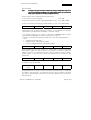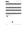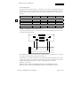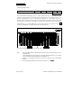
1
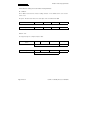
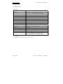
User Manual Absolute shaft encoder RA 58-P with SSI programmable Item no. 2 543 005 Item No. 2 543 005; Release: 3210799hu Release: 3210799hu Page 1 of 32 RA 58-P with SSI programmable by HENGSTLER HENGSTLER claims copyright for this documentation. This documentation shall not be modified, amended, copied or forwarded to third parties without prior written approval by HENGSTLER. HENGSTLER GmbH Postfach 11 51 78 550 Aldingen Telephone: 0 74 24/89 - 317 Telefax: 0 74 24/89 - 370 Date issued: 21.07.1999 Technical modifications and improvements which are serving the further development of HENGSTLER products are reserved. Page 2 of 32 Item No. 2 543 005; Release: 3210799hu RA 58-P with SSI programmable Contents 1 Safety and Operating Instructions ______________________________________ 5 2 Preface ____________________________________________________________ 6 3 3.1 3.2 Introduction ________________________________________________________ 6 On this manual_______________________________________________________ 7 Abbreviations ________________________________________________________ 7 4 4.1 4.1.1 4.1.2 4.2 4.3 4.4 4.4.1 4.4.2 4.4.3 4.4.4 4.4.5 4.4.6 4.4.7 4.4.8 4.4.9 4.4.10 Non-volatile memory in the RA58-P _____________________________________ 8 SSI interface _______________________________________________________ 10 Layout ____________________________________________________________ 10 Transmission procedure ______________________________________________ 11 RS232 interface _____________________________________________________ 13 Data transmission to RA58-P via RS232__________________________________ 13 Variable parameters__________________________________________________ 14 Preset_____________________________________________________________ 14 Offset _____________________________________________________________ 14 Resolution _________________________________________________________ 15 Internal encoder functions _____________________________________________ 16 Limit positions ______________________________________________________ 17 SSI output formats ___________________________________________________ 18 Special functions ____________________________________________________ 19 Switch functions _____________________________________________________ 20 Bit positions in the status byte __________________________________________ 22 Reverse reading of encoder values and set parameters ______________________ 24 5 5.1 5.2 5.3 Transmission sequence _____________________________________________ 25 Sequence of parameter entries _________________________________________ 25 Parameter default settings _____________________________________________ 25 Initial operation______________________________________________________ 25 6 Technical data _____________________________________________________ 26 7 Dimensioned drawings ______________________________________________ 29 8 Ordering Data ______________________________________________________ 32 Item No. 2 543 005; Release: 3210799hu Page 3 of 32 RA 58-P with SSI programmable Page 4 of 32 Item No. 2 543 005; Release: 3210799hu RA 58-P with SSI programmable 1 Safety and Operating Instructions This sign marks paragraphs particularly to be observed to assure proper use and to avoid risks. • The absolute shaft encoders of the type RA 58-P/RA 59-P model series are quality products manufactured in accordance with established electrical engineering standards. The units have been delivered from the factory in perfect conformance to safety regulations. To maintain this condition and to ensure trouble-free operation, please ob-serve the technical specifications of this document. • Installation and mounting may only be performed by an electrotechnical expert! • The units may only be operated within the limits specified by the technical data. • Maximum operating voltages must not be exceeded! The units are designed complying with DIN EN 61010-part 1, protection class III. To prevent dangerous structure-borne currents, the equipment has to be run on safety extralow voltage (SELV) and must be in an area of equipotential bonding. Please use an external fuse for protection (see Electrical Data). • Fields of application: industrial processes and controls. Overvoltage at the connecting terminals must be limited to overvoltage-class-II values. • Please avoid shocks to the housing – especially to the encoder shaft – and axial or radial overload to the encoder shaft. • Maximum accuracy and durability of our shaft encoders are only granted when using suitable couplings. • The high-quality EMC-specifications are only valid together with standard-type cables and plugs. When using screened cables, the screen must broadly be connected with ground on both ends. Likewise, the voltage-supply cables should entirely be screened. If this is not possible you will have to take appropriate filtering measures. • Installation environment and wiring are influential on the encoder's EMC: Thus the installer must secure EMC of the whole facility (device). • In electrostaticly threatened areas please take care for neat ESD-protection of plug and connecting cable during installation work. Item No. 2 543 005; Release: 3210799hu Page 5 of 32 RA 58-P with SSI programmable 2 Preface This manual provides information on the function of the programmable shaft encoder RA 58P and on it´s parameters. The user documentation for this encoder comprises • the installation instructions (Item no. 2543007) with informations for connection and initial operation • this user manual • the user manual (Item no. 2543006) with a description of the PC programming software 3 Introduction Absolute angle encoders supply an absolutely encoded value for any possible angular position. All such values are stored in the form of a code pattern on one or several encoder disks. The encoder disks are scannes opto-electronically. The bit patterns obtained in this procedure are amplified and fed to a microprocessor (µP). The processed values can be enquired at the SSI interface. The absolute angle encoder RA58-P resolves one encoder revolution into 4096 measuring steps (= 12 bits). The number of revolutions is 4096 (= 12 bits). This results in an encoder range of 24 2 measuring steps. The result of 12 bits + 12 bits is output together with an additional status byte as a 4 byte value. Data output is optionally possible in binary or Gray code. The angle encoder RA58-P is available in various mechanical versions (refer to the section "Dimensioned drawings" on page Fehler! Textmarke nicht definiert.). The angle encoder RA58-P can be programmed via RS232 interface. With this function the encoder can be used universally. Thus, a lot of computing time can be saved and additional processing can reduced in the automatic control systems. For remanent storage of parameters the RA58-P is equipped with an EEPROM. When the device is switched on, parameters are automatically loaded into the working memory. The RA58-P is programmed by means of a commercial MS-DOS PC via serial interface RS232. For this purpose a PC program including an adaptor cable is available (Item no. 1 543 014). The program is menu controlled and enables conveient entry and transmission of parameters. Page 6 of 32 Item No. 2 543 005; Release: 3210799hu RA 58-P with SSI programmable 3.1 On this manual In the following the term "number of measuring steps" describes the position determined by the encoder before processing in the "electronic gear". The "actual value" designates the value transmitted to the control system after processing (behind the "electronic gear"). The unit of measure for this actual value is "steps". For programming the RA58-P, the programming device (PC with programming software) transmits the corresponding configuration parameters (in the following called "CP") to the RA58-P unit. The data format in which the data are transmitted to the RA58-P is described in the section "Data transmission to RA58-P via RS232" on page 13. 3.2 Abbreviations The following abbreviations are used in this manual ccw = counter-clockwise cw = clockwise Dt = data transmission AV = actual value CP = configuration parameter LSB = least significant bit/byte MB = middle byte MF = monoflop MSB = most significant bit/byte S/rev = steps per revolution SCF = scaling factor tm = monoflop period Tp = Clock pause rev = revolution S = sign xxx = undefined µP = microprocessor Item No. 2 543 005; Release: 3210799hu Page 7 of 32 RA 58-P with SSI programmable 4 Non-volatile memory in the RA58-P The RA58-P includes two different types of data memory: • A volatile memory (RAM) which is used as a working memory into which the CP are entered after receipt from the programming device. Data stored in the volatile memory are lost when the supply voltage is switched off. • A non-volatile memory (EEPROM) which retains its data independent of the power supply. When the CP are transmitted from the programming device to the RA58-P, they are initially entered only into the working memory. After all required CP have been sent and when the encoder supplies the values in conformance with system configurations, the working memory contents can be transferred to the non-volatile memory with the command »Save into EEPROM«. When switching the power supply on, RA58-P will automatically copy the contents of the nonvolatile memory into the working memory, and the encoder then works with the data specified by the control system. With the command »RAM Default Values« all parameters in the working memory are reset to default values. In this case the encoder will transmit the original encoder steps as actual values to the control system. The originally set parameters can be retrieved with the command »Load from EEPROM «. The command sequence »RAM Default Values«, »Save into EEPROM« resets the non-volatile memory; consequently the encoder will work with an SCF of "1", a zero shift of "0" and code characteristic "cw". Page 8 of 32 Item No. 2 543 005; Release: 3210799hu RA 58-P with SSI programmable EPROM µP 80C32 SSI RS232C RAM EEPROM Preset1 Preset2 Direction Multiturn scanning; Decoding Singleturn scanning Decoding and power supply Codedisc Fig. 1: RA58-P with SSI interface (schematic layout diagram) Item No. 2 543 005; Release: 3210799hu Page 9 of 32 RA 58-P with SSI programmable 4.1 SSI interface 4.1.1 Layout Fig. 2: Block diagram of SSI interface The shift clock is supplied externally by the control system. Electrical insulation from the RA58-P is provided by an optocoupler. Encoder data and status bits are loaded into a 32-bit shift register by the microprocessor. Data are output synchronously with the external shift clock via an RS422 driver (refer to "SSI clock diagram" on page 11). Page 10 of 32 Item No. 2 543 005; Release: 3210799hu RA 58-P with SSI programmable 4.1.2 Transmission procedure Bild 3: Clock burst Bild 4: SSI clock diagram Correct data transmission requires that a defined number of pulses (i.e. a clock burst) is supplied to the shaft encoder input. Then a pause TP is required. As soon as a clock burst is present at the clock input, the current angle information is stored. With the first transition of the clock signal from High to Low c the retriggerable monoflop integrated in the shaft encoder is set; its monoflop period tm must be longer than the period T of the clock signal. With each additional falling edge the active status of the monoflop is prolonged by tm (for the last time at e). The monoflop output controls the shift register via connector P/5 . With the first transition of the clock signal from Low to High d, the most significant bit (MSB) of the angle information is supplied to the serial data output of the shaft encoder. With each additional rising edge the next less significant bit will be shifted to the data output. With a data signal length of 32 bit (single transmission), 7 status bits are output after the transmission of the least significant bit (LSB). The data line then switches to Low until the time tm has elapsed. The next data transmission with a new value can only be started when the data line switches back to High f. Item No. 2 543 005; Release: 3210799hu Page 11 of 32 RA 58-P with SSI programmable If further clock signals are sent before the monoflop period has elapsed, output will respond as follows: • Data signal length = 32 bit (single transmission): With each additional clock signal a "0" will be output. • Data signal length = 25 bit (multiple transmission): After output of 24 data bits the status bit 7 and a pause zero is output, the the output of the stored information begins from the start. At the end of a clock burst the data line remains on log. 0 (»busy«) for the duration of the monoflop period. After the monoflop period has eleapsed, the data line will be set to log. 1 (ready). When the next clock burst begins, the shift register will again be loaded with the current actual value supplied by the µP. Technical data of the SSI interface: Clock frequency: 70 kHz.....1.5 MHz Monoflop period tm: Clock burst: Multiple transmission: Delay time tV: Data refresh: 20µs ≤ tm ≤ 30 µs 32 clock pulses n • 26 clock pulses <100 ns (without cable) every 600 µs Page 12 of 32 Item No. 2 543 005; Release: 3210799hu RA 58-P with SSI programmable 4.2 RS232 interface Function: Transmission of encoder parameters to RA58-P. Reading of stored encoder parameters and encoder actual values from RA58-P. Baud rate (fixed): Byte format: Protocol: Protocol length: 2400 Baud. 1 start bit, 8 data bits, no parity, 1 stop bit. DK3964R (Siemens) 4 Byte to RA58-P 4 Byte from RA58-P (without protocol frame) RxD, TxD, signal ground Signals: DK3964R protocol: PC RA58-P STX CP no. MSB MB LSB DLE ETX BCC DLE ACK Useful data → RA58-P RA58-P PC STX MSB MB LSB XXX 1) DLE ETX BCC DLE ACK Useful data → PC 1) or status byte The "transmitter" starts data transmission with "STX". The "receiver" confirms its ready-toreceive state with "DLE". The "transmitter" then begins to transfer the useful data. The end of the protocol is triggered by the transmitter with "DLE". In order to clearly mark the end of the telegram, the useful data byte is transmitted twice if its value is "10H" (="DLE"). Then follow the characters "ETX" and "BCC" (checksum). The "receiver" acknowledges the proper receipt of the telegram with "ACK" (acknowledge). If the telegram has not been received properly, the "receiver" will answer with the character "NAK" (not acknowleded). The transmitter then repeats the entire telegram. 4.3 Data transmission to RA58-P via RS232 In the DK3964 protocol frame 4 bytes of data are transferred to the RA58-P unit. The RA58-P unit will, in return, answer with an equal set of 4 bytes of data if required. In the first byte transmitted the parameter number (CP no.) is encoded. Then the corresponding data bytes follow. These data bytes are stored in the working memory of the RA58-P unit after data transfer is completed. All data entries are made in the hexadecimal number system (H). Data which will not be evaluated are designated with "XXX" Parameter CP no. Item No. 2 543 005; Release: 3210799hu Data MSB Data MB Data LSB Page 13 of 32 RA 58-P with SSI programmable 4.4 Variable parameters 4.4.1 Preset int. Preset 01H MSB MB LSB The internal preset is an absolute preset value. After transmission of this parameter the actual values change to the set values. ext._Preset1 02H MSB MB LSB External Preset1 is an absolute preset value. After transmission of this parameter the corresponding preset values are saved. By supplying a positive voltage pulse >255 ms (debouncing time) to external preset input 1 resp. by pressing the preset button (version RS485+preset button only), the actual values change to the set value (besides the external activated preset value is also stored automatically into EEPROM). External preset 1 can be disabled or enabled (refer to "Switch functions" on page 20). ext._Preset2 03H MSB MB LSB External Preset2 is an absolute preset value. After transmission of this parameter the corresponding preset values are saved. By supplying a positive voltage pulse >255 ms (debouncing time) to external preset input 2 the actual values change to the set value (besides the external activated preset value is also stored automatically into EEPROM). External preset 2 can be disabled or enabled (refer to "Switch functions" on page 20). 4.4.2 Offset Offset 04H MSB MB LSB The offset value effects a relative shifting of the actual values. After transmission of the offset value the current actual value will be shifted by the amount of the offset value. Presets delete the set offset value. Page 14 of 32 Item No. 2 543 005; Release: 3210799hu RA 58-P with SSI programmable 4.4.3 Resolution Note: A change in the physical encoder encoder resolution by entering a scaling factor only has an effect in the data format »Standard«. In the »Tannenbaum« format, the resolution will always equal 1 regardless of entering a scaling factor or not! Encoder resolution can be modified by three different methods: 1. Direct entry of a scaling factor (SCF): CP no. 08H. 2. Entry of the number of revolutions and (required) number of steps: CP no. 09H and 0AH 3. Entry of the number of measuring steps and (required) no. of steps: CP no. 0BH and 0AH SCALING FACTOR 08H MSB MB LSB The scaling factor (SCF) is used for modifying the encoder resolution. Actual values are multiplied by the SCF. The SCF is interpreted as a number < 1. It is transmitted as an unsigned 3-byte number. Its maximum value is FF FF FFH (≈ 1 in decimal notation). If, for example, resolution is to be halved, the SCF must be 80 00 00H (= 0.5 in decimal notation). An SCF of 40 00 00H corresponds to a decimal factor of 0.25, etc. ⇒ Formula for converting the desired decimal SCF (<1) into the corresponding hexadecimal value: 24 1. multiply the decimal SCF with 2 2. round this value to a decimal integer number 3. convert the rounded number into a hexadecimal number Number of revolutions 09H XXX MB LSB A desired number of steps can be assigned to a certain number of revolutions (measuring distance) (CP no. 0AH). The range of values for the number of revolutions is 1...FFFH. The number of revolutions is an unsigned integer value. After the number of revolutions and the required number of steps have been entered, the RA58-P unit will calculate the SCF automatically. Steps 0AH MSB MB LSB Entry of required number of steps to be output for a measuring distance. The value range for the number of steps is 0...FF FF FFH. Number of measuring steps 0BH MSB MB LSB The required number of steps (CP no. 0AH) can be assigned to a number of measuring steps (measuring distance). The range of values for the number of measuring steps is 1...FF FF FFH. The number of measuring steps is an unsigned integer value. After the number of measuring steps and the required number of steps have been entered, the RA58-P unit will calculate the SCF automatically. Item No. 2 543 005; Release: 3210799hu Page 15 of 32 RA 58-P with SSI programmable 4.4.4 Internal encoder functions Save into EEPROM 1AH XXX XXX XXX The parameters stored in the working memory (RAM) are saved in the EEPROM for remanent storage. After a reset (when switching on the power supply) the parameters will be loaded into the working memory automatically. Load from EEPROM 1BH XXX XXX XXX The parameters held in remanent storage in the EEPROM are reloaded into the working memory. RAM Default Values 1CH XXX XXX XXX The working memory is deleted. All parameters are reset to default. (refer to "Parameter default settings" on page 25.) 32/25 bit mode 1DH XXX XXX LSB=0/1 With this function the physical length of the SSI shift register can be switched. LSB = 0: length= 32 bits LSB = 1: length= 25 bits (refer to "Transmission procedure" on page 11 Page 16 of 32 Item No. 2 543 005; Release: 3210799hu RA 58-P with SSI programmable 4.4.5 Limit positions All limit positions (soft limits) are set as 3-byte values. They can be freely adjusted within the value range of the encoder. A marker bit is set when the corresponding limit position has been reached. This bit can be output as a status bit at the SSI interface (refer to "bit positions on page 22). Limit 1 10H MSB MB LSB Limit 2 11H MSB MB LSB Limit 3 12H MSB MB LSB Limit 4 13H MSB MB LSB Example of an application of these limit positions: A savety range (from limit value 1 to limit value 4) and a working range (from limit value 2 to limit value 3) should be defined. Upon reaching the respective limit values, the related status bit is set and remains set as long as the condition „ current position ≥ limit value“ is fulfilled. A following control can thus evaluate these limit value status bits directly and does not need to compare each position value with the limit values any longer. This reduces the control's workload meaning that it becomes faster and the programming effort is reduced. Evaluation of the control: Current position lies within the safety range when bit 1 is set and bit 4 is not set. Current position lies within the working range when bit 2 is set and bit 3 is not set. Item No. 2 543 005; Release: 3210799hu Page 17 of 32 RA 58-P with SSI programmable 4.4.6 SSI output formats Number of bits, tannenbaum format 14H XXX XXX S/REV rev LSB In the "tannenbaum format" (please refer to chapter "Switch functions" on page 21), bit 13 and bit 14 are always located in the same bit position, independent of the selected resolution. The number of significant bits can be set separately for S/rev and rev. The numbers are 0...12 in decimal notation (= 0...CH) for the steps per revolution and 0...12 in decimal notation (= 0...CH) for the number of revolutions. Both values are encoded in the upper/lower tetrade of the LSB. If the LSB value is, for example, 9BH, 9 bits of steps per revolution (= 512 S/rev) and 11 bits of revolutions (= 2048 rev) are output. Missing bits are filled with zero. Fig. 5: Data bit arrangement in the tannenbaum format Note: 1. The tannenbaum format is designed for an encoder with a resolution of up to 13 bits singleturn data. The Encoder RA58-P however delivers 12 bit single turn data (clock pulse 13...24) and the first status bit with the bit position 7 in clock pulse 25. Therefore, the bit position 7 may not be used as a status bit in the tannenbaum format. 2. In the tannenbaum format the number system must be set to »integer integer«. integer Page 18 of 32 Item No. 2 543 005; Release: 3210799hu RA 58-P with SSI programmable No. of bits in standard format 15H XXX XXX LSB In the standard format (please refer also to "Switch functions") the number of significant bits can be set between 16...24 decimal (= 10H...18H). The data are shifted by (24 - number) bit positions towards the MSB. The remaining LS-bits are filled up with zero. Fig. 5: Data bit arrangement in the standard format. 4.4.7 Special functions Overspeed 16H XXX XXX LSB When the set overspeed value is reached, a marker bit is set (please refer also to "Bit positions" on page 22). The input format is "multiples of 100 rpm". The value range for the input is 0...255 in decimal notation (= 0...FFH) If, for example, the LSB value is 47 in decimal notation (= 2FH), the marker bit will be set at a rotational speed of 4700 rpm. Accuracy of measurement is approx. ± 5%. Item No. 2 543 005; Release: 3210799hu Page 19 of 32 RA 58-P with SSI programmable 4.4.8 Switch functions Switch functions are used for switching on/off or modifying certain encoder functions (enable/disable). In all cases the LS bit of the last byte is used for the switch function. If the LSB is 1 or 2, the function is switched on. The function is switched off when the LSB is 0. ext. Preset1 On/Off 20H XXX XXX LSB=1/0 ext. Preset2 On/Off 21H XXX XXX LSB=1/0 ext. switching forw./rev. On/Off 22H XXX XXX LSB=1/0 Gray/binary code switch 23H Two's complement/ integer/separate sign 24H XXX XXX LSB=1/0 Binary code output: LSB = 0 ; Gray code output: LSB=1 XXX XXX LSB=0/1/2 Two's complement notation: Integer notation: Separate sign: LSB = 0 LSB = 1 LSB = 2 Two's complement notation: -max.value -3, -2, -1 0 1, 2, 3 + max.value In two's complement notation (values signed) the zero point is located in the middle of the value range: (800000H...FFFFFFH, 0, 000001H...7FFFFFH with SCF=1)) Page 20 of 32 Item No. 2 543 005; Release: 3210799hu RA 58-P with SSI programmable Integer notation: 0..... max.value In integer notation (values unsigned) the zero point is located at the beginning of the value range: (000000H...FFFFFFH with SCF=1) Separate sign: VZ| +max.value 3, 2, 1 0 1, 2, 3 + max.value In the notation with separate sign the zero point is located in the middle of the value range: (FFFFFFH...800001, 0, 000001H...7FFFFFH with SCF=1). The sign is encoded separately in the MSB. In the range below zero the sign is 1, in the range above zero the sign is 0. Tannenbaum/standard format 25H XXX XXX Standard format: Tannenbaum format: LSB=0/1 LSB = 0 LSB = 1 Standard format: LSB = 0 In the standard format the number of significant bits can be set to values between 16...24 in decimal numbers. Data are shifted towards the MSB by 24 minus the number of bit positions (the encoder data are output at the SSI in MSB-justified form) The remaining LS-bits are filled with zeros (See CP no. 15H for description). The length of the shift register can optionally be set to 32 bits or to 25 bits (CP no.1DH). Tannenbaum format: LSB = 1 In tannenbaum format bit 12 and bit 13 are always located in the same bit position, independent from the selected resolution setting (see CP no. 14H for description) The length of the shift register can optionally be set to 32 bits or to 25 bits. Internal switch forw./rev. 26H XXX XXX LSB=0/1 Counter sense forward: LSB = 0 Counter sense reversed: LSB = 1 When external direction switching function is activated, LSB = 1 will reverse the counter sense selected by the external control. Item No. 2 543 005; Release: 3210799hu Page 21 of 32 RA 58-P with SSI programmable ext. length measurement (Teach in) On/Off 27H XXX XXX LSB=0/1 External preset inputs are used for starting and stopping length measurements. Requirement: The external presets 1 and 2 are both set to »On«. For starting a measurement the external preset 1 is triggered with a positive pulse. The encoder value jumps to the preset value. Preset 1 must then be deactivated again. After pacing off the measuring distance a positive pulse at external preset 2 stops the measurement for the duration of the pulse. During this period the measurement result can be read out. 4.4.9 Bit positions in the status byte When set limit values such as limit positions, overspeed values or encoder standstill are reached, bit markers will be generated. These markers can be assigned to any position in the status byte. The bit function is set by means of the CP no. Bit positions are encoded in the LSB. Bit position 1...7 is encoded in LSB bits 0, 1, 2; bit 3 is a bit switch (On/Off) for the selected function. Bit 4 switches between 1-active/0-active. Bits 5, 6, 7 are not being used. Please note:Bit position "0" is always log. 0. Bit no.: 7 6 5 4 3 2 1 0 LSB: X X X 1/0 active On/Off B.Pos2 B.Pos1 B.Pos0 Bit positions 1...7 in the status byte can be assigned to the following functions: Bit position for limit1 28H XXX XXX LSB Bit position for limit2 29H XXX XXX LSB Bit position for limit 3 2AH XXX XXX LSB Bit position for limit 4 2BH XXX XXX LSB Bit = 1 when set limit positions are reached. Page 22 of 32 Item No. 2 543 005; Release: 3210799hu RA 58-P with SSI programmable Bit position for overspeed 2CH XXX XXX LSB 2DH XXX XXX LSB 2EH XXX XXX LSB XXX LSB Bit = 1 when set overspeed value is reached. Bit position for encoder standstill. Bit = 1 in case of encoder standstill Bit position for parity Bit = 1, when parity of the 3 SSI data bytes and status byte is even Bit position for encoder error 2FH XXX Bit = 1 in case of internal encoder error (overtemperature, undervoltage, glass breakage). Bit position for direction check 30H XXX XXX LSB Bit = 1 for ccw rotation Item No. 2 543 005; Release: 3210799hu Page 23 of 32 RA 58-P with SSI programmable 4.4.10 Reverse reading of encoder values and set parameters PC → RA58-P CP no. 80H is reserved for the "reverse reading" function. In the LSB the CP no. to be read in reverse is set. Exception: Encoder actual values incl. status byte can be read with CP no. 00H. Read encoder actual values 80H XXX XXX 00H Read parameters 80H XXX XXX CP no. RA58-P → PC The reply message also comprises 4 byte of data. Transmit encoder actual values MSB MB LSB Status byte current encoder actual values Transmit parameters MSB MB LSB XXX set parameter Page 24 of 32 Item No. 2 543 005; Release: 3210799hu RA 58-P with SSI programmable 5 Transmission sequence When programming the RA58-P some parameters require that a certain transmission sequence is observed. 5.1 Sequence of parameter entries 1. »RAM Default Values« 2. Encoding characteristic 3. Scaling factor 4. Preset values 5. remaining functions (data formats, status bit functions, etc.) 6. »Save into EEPROM« (remanent data storage). 5.2 Parameter default settings The RA58-P is preset to the following parameter default values: 1. Preset: "0" 2. Offset: "0" 3. Scaling factor: "1" (encoder resolution 224 steps) 4. Encoding characteristic: cw 5. Binary data output format, two's complement notation, standard format 24 data bit + 7 status bits 6. Status bits: "0"; all status bit functions disabled 7. External inputs: disabled 8. Limit positions "0" 9. Overspeed: "0" 5.3 Initial operation No special procedures are required for taking the device into operation. Power supply, clock and data lines must be laid and connected to the control system as specified in the connection plan in the chapter "Technical data" on page 28. The easiest way for programming the encoder is to use a PC (order programming software with adapter cable under item no. 1543014). For programming via programming unit the signals RxD, TxD and signal ground must be connected. Item No. 2 543 005; Release: 3210799hu Page 25 of 32 RA 58-P with SSI programmable 6 Technical data Mechanical: Shaft diameter 6 mm (synchro-flange), 10 mm (clamping flange) Shaft load 6-mm shaft: 10-mm shaft: Maximum speed 10000 min (short-time basis), 6000 min (continuous duty) Torque ≤ 0.5 Ncm Moment of inertia Synchro-flange: 14 gcm ; clamping flange: 20 gcm Protection class (EN 60529) 1) 2) axial 60 N (13 lbs), radial 110 N (24 lbs) axial 107 N (24 lbs), radial 160 N (35 lbs) -1 -1 2 1) Housing IP 65, Bearing IP 64 2 2) Operating temperature -10 ... +60 °C Storage temperature -25 ... +85 °C Vibration performance (IEC 68-2-6) 100 m/s (10 - 500 Hz) Shock resistance (IEC 68-2-27) 1000 m/s (6 ms) Connections Cable, connector, connector+preset button Housing Aluminium Flange S= synchro-flange, K= clamping flange Weight Multi turn 350 g approx., single turn 300 g approx. Bearing life 1 x 10 revolutions (typ.) at 35% of full rated shaft load 9 1 x 10 revolutions (typ.) at 75% of full rated shaft load 8 1 x 10 revolutions (typ.) at 100% of full rated shaft load 2 2 10 IP 67 on request no standing water allowed at the shaft entrance or the ball bearing Page 26 of 32 Item No. 2 543 005; Release: 3210799hu RA 58-P with SSI programmable Electrical: General design according to EN 61010-part 1, protection class III, contamination level 2, overvoltage category II Supply voltage 10 ... 30 V DC (SELV) Induced current absorption; recommended external fuse max. 0,2 A; T 0,25 A EMC 1) Interference emissions according to EN 50081-2 Interference immunity according to EN 50082-2 Interfaces RS 485 for SSI data output RS 232c for programming Physical resolution 2) SSI baud rate 70 ... 1500 Kbit/s Function: Transmission of encoder parameters to RA58-P. Reading of stored encoder parameters and encoder actual values from RA58-P. Baud rate (fixed): 2400 Baud. Byte format: 1 start bit, 8 data bits, no parity, 1 stop bit. Protocol: DK3964R (Siemens) Protocol length: 4 Byte to RA58-P 4 Byte from RA58-P (without protocol frame) Signals: RxD, TxD, signal ground 4096 increments/4096 revolutions (24 Bit) multiturn Linearity ± ½ LSB Type of code Binary or Gray (programmable) Data update every 600 µs Programmable functions Code sequence (Direction), scaling factor, preset, offset, output format, output code External control inputs Direction, ext. Preset 1 (for version RS485+preset button Preset 1 can be activated by the button), ext. Preset 2; Inputs are only enabled when programmed to „ On“. Function is activated by 1-level (1-level= U≥10 VDC, 0-level=U≤2VDC or open). Pulse time for ext. presets >255 ms (internal fixed debouncing time) Max. cable length 1) 2) 400 m for SSI (refer to „ Recommended data transmission rate for SSI“) 20 m for programming via RS 232 (RxD and TxD) when observing the instructions for screening (see Chapter 1) actual resolution of the encoder disk; in addition, the desired resolution can be minimised by programming the encoder. Item No. 2 543 005; Release: 3210799hu Page 27 of 32 RA 58-P with SSI programmable Recommended data transmission rate for SSI: The maximum data transmission rate depends on the length of cable. For Clock/Clock and Data/Data respectively use twisted wire pairs. Use a screended cable. Cable length Baud rate < 50 m < 400 kHz < 100 m < 300 kHz < 200 m < 200 kHz < 400 m < 100 kHz Pin assignment Electrical connection Flange socket CONIN, 12-pole, ccw. Cable Signal Pin no. Colour Clock 1 green Clock 2 yellow Data 3 pink Data 4 gray RS 232 TxD 5 brown RS 232 RxD 6 white 0 V signal output 7 black Direction 8 blue Preset1 9 red Preset2 10 violet 10...30 VDC 11 white, 0.5mm 0 V (supply voltage) 12 brown, 0.5mm Page 28 of 32 2 2 Item No. 2 543 005; Release: 3210799hu RA 58-P with SSI programmable 7 Dimensioned drawings Synchro flange Item No. 2 543 005; Release: 3210799hu Page 29 of 32 RA 58-P with SSI programmable Clamping flange Page 30 of 32 Item No. 2 543 005; Release: 3210799hu RA 58-P with SSI programmable Clamping flange with connector + preset button: Button Synchro flange with connector + preset button: Button Item No. 2 543 005; Release: 3210799hu Page 31 of 32 RA 58-P mit SSI parametrierbar 8 Ordering Data Accessories: Programming software for DOS (including adapter cable), German Programming software for DOS (including adapter cable), English User manual RA 58-P with SSI, German User manual RA 58-P with SSI, English User manual PC programming software for SSI, German User manual PC programming software for SSI, English Ord. code 1 543 001 Ord. code 1 543 014 Ord. code 2 543 002 Ord. code 2 543 005 Ord. code 2 543 004 Ord. code 2 543 006 HENGSTLER GmbH Postfach 11 51 D-78 550 Aldingen Telefon: Telefax: Internet: Email: 0 74 24/8 94 07 0 74 24/8 93 70 http://www.hengstler.de [email protected] Page 32 of 32 Item No. 2 543 005; Release: 3210799hu