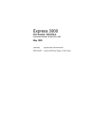
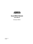
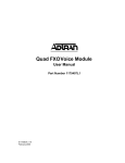
1
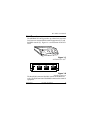
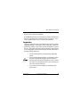
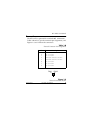
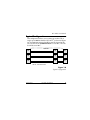
NT1 ACE3
USER MANUAL
1200236L1:
336012VUR01:
61200236L1-1A
June 1998
NT1 ACE3
Power Supply 12 VDC/800 mA
This device complies with Part 15 of the FCC rules. Operation is subject to the following two conditions: (1) This
device may not cause harmful interference, and (2) this
device must accept any interference received, including
interference that may cause undesired operation.
Changes or modifications to this unit not expressly approved by the party responsible for compliance could
void the user's authority to operate the equipment.
Canadian Standards Association
This device must be powered by a CSA approved power
supply or a power supply meeting the requirements of
CS03, Part I Section 1.4.2.
Warranties
ADTRAN will repair or replace this product within five years
from the date of shipment if it does not meet its published specifications or fails while in service. For detailed warranty, repair,
and return information, refer to the ADTRAN Equipment Warranty and Repair and Return Policy Procedure. Return Material
Authorization (RMA) is required prior to returning equipment
to ADTRAN.
901 Explorer Boulevard
P.O. Box 140000
Huntsville, AL 35814-4000
Phone: (256) 963-8000
© 1998 ADTRAN, Inc.
All rights reserved.
Printed in USA.
FCC regulations require that the following information
be provided in this manual:
1. This equipment complies with Part 68 of the
FCC rules. On the bottom of the equipment
housing is a label that shows the FCC registration
number and Ringer Equivalence Number (REN)
for this equipment. If requested, provide this information to the telephone company.
2. If this equipment causes harm to the telephone
network, the telephone company may temporarily
discontinue service. If possible, advance notification is given, otherwise, notification is given as soon
as possible. The telephone company will advise the
customer of the right to file a complaint with the
FCC.
3. The telephone company may make changes in its
facilities, equipment, operations, or procedures that
could affect the proper operation of this equipment;
advance notification and the opportunity to maintain uninterrupted service is given.
4. If experiencing difficulty with this equipment,
please contact ADTRAN for repair and warranty
information. The telephone company may require
this equipment to be disconnected from the network until the problem is corrected, or it is certain
the equipment is not malfunctioning.
5. This unit contains no user serviceable parts.
6. An FCC compliant telephone cord with a modular plug is provided with this equipment. In addition, an FCC compliant cable appropriate for the
dial backup option ordered is provided with this
equipment. This equipment is designed to be connected to the telephone network or premises wiring
using an FCC compatible modular jack, which is
Part 68 compliant.
7. The following information may be required
when applying to the local telephone company for
leased line facilities.
Service
Type
Digital Facility
Interface Code
Service
Order Code
Network
Jacks
ISDN
02IS5
6.0F
RJ-49C
CANADIAN EMISSIONS REQUIREMENTS
This digital apparatus does not exceed the Class B limits for
radio noise emissions from digital apparatus as set out in the
interference-causing equipment standard entitled "Digital
Apparatus," ICES-003 of the Department of Communications.
Cet appareil numerique respecte les limites de bruits radioelectriques applicables aux appareils numeriques de Class B prescrites dans la norme sur le materiel brouilleur: "Appareils
Numeriques," NMB-003 edictee par le ministre des Communications.
CANADIAN EQUIPMENT LIMITATIONS
Notice: The Canadian Industry and Science Canada label identifies certified equipment. This certification means that the equipment meets certain telecommunications network protective,
operational, and safety requirements. The Department does not
guarantee the equipment will operate to the user’s satisfaction.
Before installing this equipment, ensure that it is permissible to
be connected to the facilities of the local telecommunications
company. The equipment must also be installed using an
acceptable method of connection. In some cases, the company’s inside wiring associated with a single-line individual
service may be extended by means of a certified connector
assembly (telephone extension cord). Compliance with the
above conditions may not prevent degradation of service in
some situations.
Repairs to certified equipment should be made by an authorized Canadian maintenance facility designated by the supplier.
Any repairs or alterations made by the user to this equipment,
or equipment malfunctions, may give the telecommunications
company cause to request the user to disconnect the equipment.
Users should ensure for their own protection that the electrical
ground connections of the power utility, telephone lines, and
internal metallic water pipe system, if present, are connected
together. This precaution may be particularly important in
rural areas.
Users should not attempt to make such connections themselves, but should contact the
appropriate electric inspection authority,
or an electrician, as appropriate.
The Load Number (LN) assigned to each terminal device
denotes the percentage of the total load to be connected to a
telephone loop which is used by the device, to prevent overloading. The termination on a loop may consist of any combination of devices subject only to the requirement that the total
of the Load Numbers of all devices does not exceed 100.
Table of Contents
Unit Overview ...............................................................
LED Indicators...............................................................
Inspection .......................................................................
Maintenance...................................................................
Remote Testing ..............................................................
Repair and Return .........................................................
Connections....................................................................
1
2
3
4
4
4
5
Powering with the NT1 ACE3 Power Supply ........... 7
Connecting the Terminal Equipment......................... 8
Typical Configuration .................................................. 9
Troubleshooting .......................................................... 10
Specifications ............................................................... 12
Network Interface (U) ............................................ 12
Customer Interface (S/T) ....................................... 12
Faceplate Indicators................................................ 12
Network Compatibility.......................................... 13
Mechanical............................................................... 13
Power ........................................................................ 13
Environmental......................................................... 13
Power Supply Specifications................................. 13
61200236L1-1
NT1 ACE3 User Manual
i
Table of Contents
FIGURES
Figure 1-1. ADTRAN NT1 ACE3 ........................................1
Figure 1-2. 1Interface Connectors .......................................1
Figure 1-3. Network Connector (RJ-45) ............................. 5
Figure 1-4 . Local Bus Connector (RJ-45) ............................6
Figure 1-5. Power Supply Connection ................................7
Figure 1-6. Typical Configuration........................................9
TABLES
Table 1-A. Status Indicators................................................. 2
Table 1-B. Network Connector Pin Assignments ............. 5
Table 1-C. Local Bus Connector Pin Assignments ........... 6
ii
NT1 ACE3 User Manual
61200236L1-1
NT1 ACE3 User Manual
Unit Overview
The ADTRAN NT1 ACE3 provides up to three basic rate interfaces between customer ISDN terminal equipment (S/T) and
the ISDN network (U). Figure 1-1 is an illustration of the NT1
ACE3.
3
2
1
READY
ERROR
READY
ERROR
READY
ERROR
NT1 ACE3
Figure 1-1
ADTRAN NT1 ACE3
12VDC
3
POWER
S/T
2
U
S/T
1
U
S/T
U
Figure 1-2
Interface Connectors
The three RJ-45 connectors labeled U connect to the ISDN network. The RJ-45 connectors labeled S/T connect to the terminal
equipment.
61200236L1-1
NT1 ACE3 User Manual
1
NT1 ACE3 User Manual
The U-interface complies with ANSI T1.601 and ITUTI.430 recommendation Standard. The S/T-interface complies with ANSI T1.605 and ETSI ETS 300012 Standard.
The ADTRAN NT1 ACE3 is a stand-alone unit. An external
power source is provided for the NT1 ACE3. External power
is supplied by the ADTRAN Power Supply, part number
336012VUR01.
LED Indicators
Table 1-A describes the status of the LEDs located on the
front panel of the NT1 ACE3. There is a Ready and Error indicator for each port of the NT1 ACE3.
Table 1-A
Status Indicators
LED
Color
Description
READY
Green
S/T and U- interfaces ready
to place call
ERROR
Red
S/T or U-interface not ready
If an ERROR indicator is illuminated, check the flash rate of
the READY indicator to determine the source of the error. A
faster 8 Hz flash rate (8 flashes per second) indicates a
2
NT1 ACE3 User Manual
61200236L1-1
NT1 ACE3 User Manual
network problem. A slower 1 Hz rate (1 flash per second) indicates an S/T interface problem.
If an ERROR indicator is not illuminated and the READY indicator is flashing, then a network test is in progress. Network command tests cause a faster 8 Hz flash rate.
Inspection
After unpacking the unit, immediately inspect it for possible
shipping damage. If damage is discovered, file a claim immediately with the carrier; then contact ADTRAN Customer
Service. If possible, keep the original shipping container for
use in shipping the NT1 ACE3 for repair or for verification of
damage during shipment.
• Never install telephone wiring during a lightning
storm.
• Never install telephone jacks in wet locations unless
the jack is specifically designed for wet locations.
• Never touch uninsulated telephone wires or terminals unless the telephone line has been disconnected at the network interface.
• Use caution when installing or modifying telephone lines.
61200236L1-1
NT1 ACE3 User Manual
3
NT1 ACE3 User Manual
Maintenance
The ADTRAN NT1 ACE3 requires no routine maintenance to
operate. In case of equipment malfunction, refer to the sections Remote Testing on page 4 and Repair and Return on
page 4 or remove the unit and replace it with another unit
optioned in an identical manner.
Remote Testing
Network test features include a loopback test initiated at the central office. This test confirms network integrity to the NT1 ACE3.
Repair and Return
Repairs should not be performed in the field. Repair services
can be obtained by returning the unit to the ADTRAN Customer and Product Service (CAPS) Department at the address listed on the inside back cover of this manual.
4
NT1 ACE3 User Manual
61200236L1-1
NT1 ACE3 User Manual
Connections
The NT1 ACE3 is optioned for standard 100Ω termination.
Tables 1-B and 1-C give the connector pin assignments, and
Figures 1-3 and 1-4 show the connectors.
Table 1-B
Network Connector Pin Assignments
Pin
1
2
3
4
5
6
7
8
Description
No connection
No connection
No connection
U-interface network connection
U-interface network connection
No connection
No connection
No connection
PIN 1
PIN 8
Figure 1-3
Network Connector (RJ-45)
61200236L1-1
NT1 ACE3 User Manual
5
NT1 ACE3 User Manual
Table 1-C
Local Bus Connector Pin Assignments
Pin
1
2
3
4
5
6
7
8
Description
No connection
No connection
S/T interface Receive Power Source 1 (Negative)
S/T interface Transmit Power Source 1 (Positive)
S/T interface Transmit Power Source 1 (Positive)
S/T interface Receive Power Source 1 (Negative)
No connection
No connection
PIN 1
PIN 8
Figure 1-4
Local Bus Connector (RJ-45)
6
NT1 ACE3 User Manual
61200236L1-1
NT1 ACE3 User Manual
Powering with the NT1 ACE3 Power Supply
The ADTRAN NT1 ACE3 Power Supply, part number
336012VUR01, provides power to the NT1 ACE3. To connect
the NT1 ACE3 to the external power supply, perform the following steps as illustrated in Figure 1-5.
1. Connect the Power Supply to the NT1 ACE3 at the
POWER jack located on the NT1 ACE3 rear panel.
2. Plug the Power Supply into the nearest wall outlet
supplying 120 VAC, 60 HZ.
3. On the NT1 ACE3, verify that the ERROR indicators are illuminated. After approximately 15 seconds, the READY indicators should flash at a 1 Hz
rate. Should any of the indicators fail to operate as
stated, see the section Troubleshooting on page 10.
100 - 120
VAC
NETWORK
LOCAL
3
2
1
READY
ERROR
READY
POWER
ERROR
READY
ERROR
NT1 ACE3
Figure 1-5
Power Supply Connection
61200236L1-1
NT1 ACE3 User Manual
7
NT1 ACE3 User Manual
Connecting the Terminal Equipment
After successfully powering up the NT1 ACE3, the ERROR
indicators should be on and the READY indicators should be
flashing. Make sure that terminal equipment (TE) is properly terminated. Plug each TE into one of the S/T connectors at
the rear of the unit.
The ERROR indicators should extinguish a few seconds after
power is applied to the TE. If the ERROR indicators fail to go
out, see the section Troubleshooting on page 10.
As ERROR indicators extinguish, READY indicators should
illuminate. A few seconds after the READY indicators illuminate, a call can be placed or received. If the READY indicators
fail to illuminate or if you are unable to place or receive calls,
see the section Troubleshooting on page 10.
8
NT1 ACE3 User Manual
61200236L1-1
NT1 ACE3 User Manual
Typical Configuration
This configuration allows you to connect up to three TEs at
ranges up to 3000 feet from the NT1 ACE3, as shown in Figure
1-6. A termination resistor should be centrally located to the
TEs. The NT1 ACE3 TERMINATION is set to 100 Ω. The TEs
should be set to 100 Ω.
3,000 Feet
*
TR
*
TR
NT1
*
TR
*
TR
NT1
*
TR
*
TR
NT1
*TR= 100Ω Termination Resistor
Figure 1-6
Typical Configuration
61200236L1-1
NT1 ACE3 User Manual
9
NT1 ACE3 User Manual
Troubleshooting
If your NT1 ACE3 does not operate properly, please check
the list of symptoms and solutions below. For further assistance, please contact ADTRAN Technical Support at
888 4ADTRAN.
ERROR and READY indicators not illuminated.
• Check the power source to the NT1 ACE3 for sufficient power.
• The NT1 ACE3 power supply may be defective:
Call ADTRAN Technical Support.
• The NT1 ACE3 may be defective: Call ADTRAN
Technical Support.
ERROR indicators illuminated, READY indicators flash at a
faster 8 Hz rate.
Network activation failure:
• Wall jack wiring is incorrect: Check wall jack.
• Problem with ISDN line: Contact telephone company.
10
NT1 ACE3 User Manual
61200236L1-1
NT1 ACE3 User Manual
ERROR indicators illuminated, READY indicators flash at a
slower 1Hz rate.
Local bus failure:
• TE not connected: Connect TE.
• TE not receiving power from NT1: Consult TE
documentation.
• TE not terminated properly: Correct termination.
• TE ISDN parameters not configured properly: Reconfigure TE (SPIDs, LDNs, switch type, etc.).
READY indicators do not illuminate.
• Problem with ISDN network: Contact telephone
company.
• ISDN line not plugged into U jack: Plug ISDN line
into U jack.
Unable to make or receive a call.
• TE is not compatible with ISDN network: Contact
telephone company.
• TE ISDN parameters not configured properly: Reconfigure TE (SPIDs, LDNs, switch type, etc.).
61200236L1-1
NT1 ACE3 User Manual
11
NT1 ACE3 User Manual
Specifications
Network Interface (U)
Line............................. 2-Wire (Tip and Ring)
Operating Mode .......... Full-Duplex
Data Rate .................... 160 kbps total, 144 kbps to customer
Signal Format............... 2B1Q
Output Amplitude ......... 2.5 volts, zero-to-peak
Tx Source Impedance .... As per ANSI T1.601
Rx Source Impedance.... As per ANSI T1.601
Receiver Sensitivity........ As per ANSI T1.601
Customer Interface (S/T)
Line............................. 4-Wire (Tx and Rx Pair)
Operating Mode .......... Full-Duplex
Data Rate .................... 192 kbps total, 144 kbps to customer
Signal Format............... Alternate Mark Inversion, 100% duty cycle
Output Amplitude ......... 0.75 volt, zero-to-peak
Tx Source Impedance .... As per ANSI T1.605
Rx Source Impedance.... As per ANSI T1.605
Receiver Sensitivity........ As per ANSI T1.605
Faceplate Indicators
ERROR .................. U-interface or S/T interface not ready
READY .................. Steady light - Network ready to place a call
8 Hz (faster) flashing - U-interface not ready
1 Hz (slower) flashing - S/T interface not ready
12
NT1 ACE3 User Manual
61200236L1-1
NT1 ACE3 User Manual
Network Compatibility
U Interface............. ISDN U
S/T Interface.......... ISDN S/T
Mechanical
Size...................... 9.0" wide, 6.375" deep,
1.625" high
Weight ................. 1.5 lbs
Mounting............... Wall or desktop
Power
12 VDC ................ 3.3 W dissipation
Environmental
Temperature .......... 0 to 40 °C (32 to 104 °F) operating
-20 to 70 °C (-4 to 158 °F) storage
Relative Humidity.... Up to 95%, non-condensing
Power Supply Specifications
Size............................ 3.0" long, 2.5“ wide, 1.9" high
Weight ....................... 1.5 lb
Power Input ................. 110 VAC, 60 Hz
Voltage ....................... 12 VDC/800 mA
61200236L1-1
NT1 ACE3 User Manual
13
NT1 ACE3 User Manual
14
NT1 ACE3 User Manual
61200236L1-1
Technical Support and Warranty Information
Presales Inquiries and Applications Support
Please contact your local distributor, ADTRAN Applications
Engineering, or ADTRAN Sales:
Applications Engineering
800) 615-1176
Sales
(800) 827-0807
Post-Sale Support
Please contact your local distributor first. If your local distributor cannot help, please contact ADTRAN Technical Support and have the unit serial number available.
Technical Support
(888) 4ADTRAN
Repair and Return
If ADTRAN Technical Support determines that a repair is
needed, Technical Support will coordinate with the Customer
and Product Service (CAPS) department to issue an RMA
number. For information regarding equipment currently in
house or possible fees associated with repair, contact CAPS
directly at the following number:
CAPS Department
(256) 963-8722
Identify the RMA number clearly on the package (below
address), and return to the following address:
ADTRAN Customer and Product Service
6767 Old Madison Pike
Progress Center/ Building #6 Suite 690
Huntsville, Alabama 35807
RMA # _____________