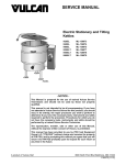
1
Model SEC 400
Hog Splitting Saw
EQUIPMENT
SELECTION . . . . . . . . . . Ordering No.
SEC 400 without Controller
42V/50Hz (21 inch Blade) . . . . . 4004077
230V/60Hz (16 inch Blade) . . . . 4004076
460V/60Hz (16 inch Blade) . . . . 4004086
SEC 400 with Mechanical Brake
for Part Numbers: . . . . . . . . . . See pg. 13
SEC 400 with Thin Head (16 inch Blade)
230V/60Hz (Electric / DC Brake) 4004135
460V/60Hz (Mechanical Brake) . 4004132
SEC 400 with Electric / DC Braking
for Part Numbers: (3 Phase) . See pg. 14
Balancer
Mechanical Brake . . . . . . . . . . . . 4042049
Electric Brake . . . . . . . . . . . . . . . 4042036
JARVIS
6204004;.
TABLE OF
CONTENTS . . . . . . . . . . . . . . . . . . . . . . . . . . . . Page
• Safety Messages to Employer and Safety
Director . . . . . . . . . . . . . . . . . . . . . . . . . . . . . . . . . 2
• Safety Messages to Operators, Maintenance
and Cleanup Personnel . . . . . . . . . . . . . . . . . . . 3
• Parts Diagram and List . . . . . . . . . . . . . . . . . . . . 4
• Wiring Diagrams . . . . . . . . . . . . . . . . . . . . . . . . 16
• Special Tools . . . . . . . . . . . . . . . . . . . . . . . . . . . 19
• Specifications . . . . . . . . . . . . . . . . . . . . . . . . . . . 20
• Installation Instructions . . . . . . . . . . . . . . . . . . . 20
• Operation Instructions . . . . . . . . . . . . . . . . . . . . 20
• Maintenance Instructions . . . . . . . . . . . . . . . . . 21
® PRODUCTS CORPORATION
33 ANDERSON ROAD, MIDDLETOWN, CONNECTICUT 06457--4926
UNITED STATES OF AMERICA
TEL. 860--347--7271
[email protected]
FAX. 860--347--6978
WWW.jarvisproducts.com
safety messages to employer
and safety director
Model SEC 400
page 2 of 24
Keep hands clear.
SAFETY MESSAGES TO EMPLOYER AND SAFETY DIRECTOR
AVOID INJURY
1. Remove and repair any tool that malfunctions. All personnel must be instructed to remove any malfunctioning equipment.
2. Ensure that all employees who use this tool are trained in the proper use of this tool and are aware of
the dangers that may arise if they do not follow procedures outlined in this brochure.
3. Ensure that all employees are instructed not to walk in front of the tool during its use.
4. Enclosed are four (4) copies of “NOTICE TO OPERATORS, MAINTENANCE AND CLEANUP
PERSONNEL.” Post one copy on the employees’ bulletin board; give one copy to the operator(s);
give one copy to the maintenance foreman; and give one copy to the sub--contract cleanup / internal
cleanup foreman. Additional copies will be provided upon request.
5. The tool is designed and intended to be powerful. This fact should be obvious to your employees, but
you must emphasize it to them.
6. Ensure that eye protection is worn in accordance with OSHA’s eye and face protection requirements
(29 CFR 1910.133) when operating tool.
7. Never make modifications or alterations to the tool. Replace any missing or illegible labels.
8. Ensure that proper procedures are established in accordance with OSHA’s lockout/tagout procedures
(29 CFR 1910.147) to prevent accidental startup or release of stored energy.
9. Follow our installation and maintenance instructions for proper installation and care of the tool.
10. Avoid injury. Do not permit the tool to be misused.
11. If you resell or distribute a Jarvis product, you must provide the purchaser with the appropriate safety
sheets and tool brochure. Additional copies of safety sheets and tool brochures will be provided upon
request.
JARVIS
6204004;.
®
PRODUCTS CORPORATION
33 ANDERSON ROAD, MIDDLETOWN, CONNECTICUT 06457--4926
UNITED STATES OF AMERICA
TEL. 860--347--7271
[email protected]
FAX. 860--347--6978
WWW.jarvisproducts.com
safety messages to operators,
maintenance and cleanup personnel
Model SEC 400
page 3 of 24
Keep hands clear.
SAFETY MESSAGES TO OPERATORS, MAINTENANCE AND CLEANUP
PERSONNEL
REMOVE ANY MALFUNCTIONING TOOL FROM SERVICE
REPORT ANY PROBLEMS TO YOUR SUPERVISOR
1. Disconnect the power supply in accordance with OSHA’s lockout/tagout procedures (29 CFR
1910.147) before making any blade changes.
2. Disconnect the power supply in accordance with OSHA’s lockout/tagout procedures (29 CFR
1910.147) before performing any repair or maintenance.
3. Disconnect the power supply -- or have the power supply disconnected -- in accordance with OSHA’s
lockout/tagout procedures (29 CFR 1910.147) before performing any cleanup.
4. Disconnect the power supply when the tool is not being used.
5. Always wear eye protection in accordance with OSHA’s eye and face protection requirements (29 CFR
1910.133) when operating the tool.
6. Never put fingers, hands or other parts of the body on the cutting edge or within the cutting path of the
tool.
7. Never allow people to walk in front of the tool during its use.
8. Never allow people to hold / restrain the carcass while operating the tool.
9. Test the tool prior to use or daily. Depress each trigger separately and the tool should not start. Depress
one trigger, then pause one second and depress the other trigger and the tool should not start. Repeat
this procedure reversing the triggers. Depress both triggers simultaneously and the tool should start.
With the tool running, release one trigger and the tool should stop. Continue holding the depressed
trigger and then depress the other trigger. The tool should not start. Repeat this procedure holding the
other trigger. If the tool malfunctions, remove it from service and report or repair it immediately.
10. Test the brake prior to use or daily. After releasing either or both triggers, the blade should stop within
1.5 seconds. If the tool malfunctions, remove it from service and report or repair it immediately.
11. Never depress the triggers unless you want to use or test the tool.
12. Never make modifications or alterations to the tool. Report or replace any missing or illegible labels.
13. Always use both hands when starting and operating the tool to avoid the risk of possible “kick back”
or “recoil”. Continue holding the tool with both hands until the saw blade comes to a complete stop.
JARVIS
6204004;.
®
PRODUCTS CORPORATION
33 ANDERSON ROAD, MIDDLETOWN, CONNECTICUT 06457--4926
UNITED STATES OF AMERICA
TEL. 860--347--7271
[email protected]
FAX. 860--347--6978
WWW.jarvisproducts.com
parts diagram and list
Model SEC 400
page 4 of 24
Figure A
*
***
*
**
*
ITEM
1
2
3
4
5
6
7
8
9
10
11
12
13
14
15
16
17
18
19
20
21
22
23
24
25
26
27
28
29
30
31
32
33
PART NO.
1055749**
1012076
1023297
1023284
1023290
1010360
1030053
1020222
1055746
1038011
1002312
1035371
1035256
1032322
1021328
1026151
1026199
1013212
1021276
1016462
1055613
1004245
1042266*
1042339
1055743
1018120
1019140
1010334
3005026
1063009
1035375
1002314
1055744
1011305
1001122
1059056*
1014150
PART NAME
QTY
Hex Head Screw
1
Blade Clamp
1
Standard Blade (16 inch)
1
Saw Blade (18 inch)
Saw Blade (21 inch)
Dowel Pin
2
Key
2
Blade Mounting Shaft
1
(includes item 4)
Socket Head Cap Screw
4
Grease Fitting
2
Gear Box Cover
1
O--ring
1
Shaft Seal
1
Bearing Plate
1
Ball Bearing
1
Crown Gear, Std
1
Crown Gear, Low Speed
Retaining Ring
1
Cylindrical Bearing
1
Gear Housing (2.84 dia.)
1
Hex Head Screw
2
Flat Washer
1
Ft Hdl Bkt (2.44 dia Gr Hsg)
1
Ft Hdl Bkt (2.84 dia Gr Hsg)
1
Set Screw
2
Trigger Lever (with Item 33)
1
Front Handle Grip
1
Threaded Pin
4
Switch Assembly
1
Wire Nut
2
O--ring
1
Front Handle Cover
1
Socket Head Cap Screw
3
Connector
1
Molded Plug and Wire
1
Hose Assembly
1
Compression Spring
1
JARVIS
6204004;.
®
*
*
* For spare parts only, not in current tools.
** Tighten to 65 lbf--ft.
*** Install open end facing blade.
ITEM PART NO.
PART NAME
QTY
34
1055753
Hex Head Screw
7
35
1004232
Split Lock Washer
7
36
1035372
O--ring
1
37
1021327
Needle Bearing
1
38
1026164
Pinion Gr. Sft (Splined, 15T)
1
1026180* Pinion Gr. Sft (Tang, 15T)
1026198
Pinion Gr. Sft (Splined, 13T)
Low Speed
39
1063220
Connector
1
40
1036190
Inner Ring Bushing
1
41
1013237
Retaining Ring
1
42
1013243
Retaining Ring
2
43
1021329
Ball Bearing
1
44
1035537
Oil Seal
1
45
1013208
Thrust Ring
1
46
1055617
Socket Head Cap Screw
6
47
1011301
Splined Coupling
1
48
1035534
O--ring
1
49
1030052* Key
2
50
1054132* Special Screw
1
51
1035367
Guard Gasket
1
52
1055748
Socket Head Cap Screw
2
53
1038025* Grease Relief Fitting
1
54
1050607
Hex Head Plug
1
55
1024125
Blade Guard (16 inch blade)
1
1024128
Blade Guard (18 inch blade)
1024131
Blade Guard (21 inch blade)
56
1055750
Hex Head Screw
2
3016271
Gear Hsg. Assy (incls. 1, 2,
4--17, 34--38, 40--46 and 54)
3016381
Gear Hsg. Assy, Low Speed
3019143
Front Handle Assy (incls.
items 18--31, 33, 39 and 52)
3011022
Coupling and Seal Assy
(incls. items 47 and 48)
3013005
Thrust Ring Seal Assy
(incls. items 44 and 45)
PRODUCTS CORPORATION
33 ANDERSON ROAD, MIDDLETOWN, CONNECTICUT 06457--4926
UNITED STATES OF AMERICA
TEL. 860--347--7271
[email protected]
FAX. 860--347--6978
WWW.jarvisproducts.com
parts diagram and list
Model SEC 400
page 5 of 24
Figure B
**
*
* For spare parts only,
*
not in current tools
** Install open end facing fan
ITEM PART NO.
PART NAME
QTY
57 1055751 Hex Head Screw
2
58 1004233 Split Lock Washer
2
59 1042271 Hanger
1
60 1055752 Hex Head Screw
4
61 1004231 Split Lock Washer
15
62 1002308 Front Motor Cover
1
63 1035370 O--ring
2
64 3063037 Stator Assembly, 460/230V,
1
60Hz; 380/200V, 50Hz
3063041 115V, 50Hz
3063042 42V, 50Hz
3063047 575V, 60Hz
3063110
380V, 60Hz
3063123 208V, 60Hz
3063125 415V, 50Hz
3063127 220V, 50Hz
65 1055757 Set Screw (with Item 64)
2
66 1021302 Ball Bearing
1
67 1013207 Bearing Retaining Ring
1
68 1055754 Hex Head Screw
3
69 1064038 Rotor (Spline Drive)
1
1064028* Rotor (Tang Drive)
1
70 1021330 Ball Bearing
1
71 1014101 Wave Spring
1
72 1002307 Rear Motor Cover
1
1002553 Rear Motor Cover, 42 & 115V
73 1035368 Shaft Seal
1
74 1061527 Fan Driver
1
75 1030051 Key
1
76 1061528 Fan
1
77 1004229 Fender Washer
2
78 1055755 Hex Head Screw
6
79 1017081 Danger Label
1
80 1055779* Cheese Head Screw
4
81 1035282 O--ring
1
82 1032397 Adapter Plate
1
83 1011286
Connector, Straight, 42 & 115V
1
84 1055845 Pan Head Screw
4
85 1011304
Connector, Elbow
1
86 1035457 Gasket
1
87 3005042 Switch Assembly
1
88 1004234 Serrated Lock Washer
1
89 1063414 Motor Conduit
1
1063524 Motor Conduit, 42 & 115V
90 1035374 Grommet
1
JARVIS
6204004;.
®
*
*
ITEM
91
92
93
94
95
96
97
98
99
100
101
102
103
104
105
106
107
108
109
110
111
112
113
114
115
116
117
PART NO.
1035373
1035366
1002313
1004230
1017085
1017158
1055039
1010504
1055720
1019139
1018121
1014153
1055838
1032357
1055747
1061530
1055611
1002306
1002315
1002320
1017168*
1030068
1009124*
1029301
1024126
1042272
1055790
see page 6
3019144
8039097
PART NAME
QTY
O--ring
1
Electrical Box Gasket
1
Electrical Box Cover
1
Split Lock Washer
4
Electrical Label
1
Information Label
1
Drive Screw
4
Roll Pin
1
Button Head Screw
2
Rear Handle with item 98
1
Trigger Lever with item 102
1
Compression Spring
2
Oval Head Screw
4
Air Inlet Plate
1
Socket Head Cap Screw
1
Plug
1
Socket Head Cap Screw
5
Fan Cover
1
Motor Cover
1
Motor Cover, 42 & 115V
Nameplate Label
2
Key
1
Sleeve (incl. with item 69)
1
Spacer
3
Splash Guard
1
Splash Guard Bracket
1
Hex Head Screw
2
Cord Assembly
1
Rear Handle Assy (includes
items 24, 34, 35, 61, 81,
87, 98--102)
Complete Tool Kit -- pg 19
PRODUCTS CORPORATION
33 ANDERSON ROAD, MIDDLETOWN, CONNECTICUT 06457--4926
UNITED STATES OF AMERICA
TEL. 860--347--7271
[email protected]
FAX. 860--347--6978
WWW.jarvisproducts.com
parts diagram and list
Model SEC 400
page 6 of 24
Figure C
Mechanical Brake Parts
ITEM
117
PART NO.
3001018
1063634
1063638
1001080
3001021
1063628
1063626
1001080
3001019
1063751
1063805
1012091
1001127
1
3001022
1063760
1063849
1001127
1035538
PART NAME
QTY
DC Brake:
200--460V
Cord and Conn. with Insert
1
Conn. with Male Pins Insert
Insert with Male Pins
Cord, 7 Conductor, 20 ft
575V
Cord and Conn. with Insert
1
Connector Shell
Insert with Male Pins
Cord, 7 Conductor, 20 ft
Mechanical Brake:
200--460V
Cord & Conn, Mech. Brake
1
Conn. with Male Pins Insert
Insert with Male Pins
Cable Clamp
Cord, 9 Conductor
115V Mech. Brake
Cord & Conn., Mech. Brake
1
Conn. with Male Pins Insert
Insert with Male Pins
Cord, 9 Conductor
Oil Seal
1
JARVIS
6204004;.
®
ITEM
2
3
4
5
6
7
8
9
10
11
12
13
14
15
16
17
PART NO.
1055753
1004017
1042347
1016469
1035496
1014155
1013127
1032451
1011311
1055117
1063244
1001126
1002371
1004231
1055934
1072048
1072049
18
19
20
21
1004015
1055946
1055613
1004232
3061215
3061216
3061217
PART NAME
QTY
Hex Head Screw
10
Flat Washer
4
Hanger
1
Brake Housing with item 1
1
O--ring
1
Wave Spring
1
Retaining Ring
1
Splined Plate
1
Splined Coupling
1
Round Head Screw
2
Ring Tongue
2
Wire
4 ft
Front Motor Cover
1
Lock Washer
9
Hex Head Screw
6
Brake Coil, 115--575V
1
Brake Coil, 42V only
(incl. items 18 and 19)
1
Lock Washer
4
Socket Head Cap Screw
4
Hex Head Screw
3
Lock Washer
6
Mechanical Brake Kit, 115V
Mechanical Brake Kit, 230V
Mechanical Brake Kit, 460V
PRODUCTS CORPORATION
33 ANDERSON ROAD, MIDDLETOWN, CONNECTICUT 06457--4926
UNITED STATES OF AMERICA
TEL. 860--347--7271
[email protected]
FAX. 860--347--6978
WWW.jarvisproducts.com
parts diagram and list
Model SEC 400
page 7 of 24
Figure D
Thin Head
*
*
*
* Shim package contains 3 shims 0.005 inch thick
and 6 shims 0.002 inch thick. Install only as
many shims as necessary to obtain proper fit.
ITEM
1
2
3
4
5
6
7
8
9
10
11
12
13
14
15
16
17
18
19
20
21
22
23
24
PART NO.
1007337
1012106
1023297
1023284
1023290
1002413
1010448
1035559
1035558
1010449
1026203
1027067
1021406
1021407
1029350
3069001*
1012107
1027066
1029349
1013271
1030073
1026202
1026201
1050607
1055020
1016552
PART NAME
Hex Nut
Blade Clamp
Standard Blade (16 inch)
Saw Blade (18 inch)
Saw Blade (21 inch)
Gearbox Cover
Dowel Pin
Shaft Seal
O--ring
Dowel Pin (with item 9)
Gear and Blade Shaft
Short Stud
Tapered Bearing Cone
Tapered Bearing Cup
Thin Spacer
Shim Package
Bearing Clamp
Long Stud
Thick Spacer
External Retaining Ring
Key
Helical Spur Gear
Spiral Bevel Ring Gear
Hex Head Plug
Socket Head Cap Screw
Gear Housing
JARVIS
6204004;.
QTY
1
1
1
1
2
1
1
2
1
1
4
4
1
3
1
1
1
1
2
1
1
1
6
1
®
ITEM
25
26
27
28
29
30
31
32
33
34
35
36
37
38
39
40
41
42
43
44
45
46
47
PART NO.
1038011
1035514
1007336
1007335
1021327
1035435
1004272
1055921
1055753
1004232
1016553
1035372
1026200
1036190
1013237
1013243
1021329
1035537
1013208
1055617
1035557
1024210
1024284
1055750
3016382
PART NAME
Grease Fitting
O--ring
Hex Nut, Left Hand
Hex Nut
Needle Bearing
O--ring
Split Lock Washer
Hex Head Screw
Hex Head Screw
Split Lock Washer
Intermediate Housing
O--ring
Spiral Bevel Pinion Gear
Inner Ring Bushing
External Retaining Ring
External Retaining Ring
Ball Bearing
Oil Seal
Thrust Ring
Socket Head Cap Screw
Guard Gasket
Blade Guard, 16 inch
Blade Guard, 18 inch
Hex Head Screw
Gear Housing Assembly
(incls items 1, 2, 4--45)
QTY
2
2
1
1
1
1
2
2
6
6
1
1
1
1
1
2
1
1
6
1
1
2
PRODUCTS CORPORATION
33 ANDERSON ROAD, MIDDLETOWN, CONNECTICUT 06457--4926
UNITED STATES OF AMERICA
TEL. 860--347--7271
[email protected]
FAX. 860--347--6978
WWW.jarvisproducts.com
parts diagram
Model SEC 400
page 8 of 24
Figure E
Thin Head Gear Housing
Assembly
(Section View)
Place Shims Here to Set Bevel Gear Backlash
Long Stud: Use 6 mm Allen Wrench to Hold
Gear Housing
Short Stud: Use 6 mm Allen Wrench to Hold
Bearing Clamp
Left Hand Thread
Tapered Bearing
Cone
Hex Nut
Left Hand
Thread
Hex Nut
Tapered
Bearing Cup
Tapered
Bearing Cone
Clearance Setting
Tapered
Bearing Cone
Intermediate Housing
Tapered Bearing Cup
Spacer
Gear and Blade Shaft
Place or Remove Shims Here
to Set Bearing Cone Clearance.
Clearance Setting
Bevel Gear
Spacer
Retaining Ring
Place or Remove Shims Here
to Set Bearing Cone Clearance.
Notes
1. Set bearing cone clearance:
IF tight, add shims to achieve proper fit; replace spacers if necessary.
2.
3.
4.
5.
IF loose, remove shims to achieve proper fit.
Backlash of bevel gears should be 0.003 to 0.007 inch.
Bevel side of retaining ring must be facing away from gear housing.
Use Loctite 262 on hex nuts.
Pack all bearing cones and bearing cups with Jarvis 1315
White Grease when clearance adjustments are completed.
JARVIS
6204004;.
®
PRODUCTS CORPORATION
33 ANDERSON ROAD, MIDDLETOWN, CONNECTICUT 06457--4926
UNITED STATES OF AMERICA
TEL. 860--347--7271
[email protected]
FAX. 860--347--6978
WWW.jarvisproducts.com
parts diagram and list
Model SEC 400
page 9 of 24
Figure F
Electric Control Box
Mechanical Brakes
(Except 42 Volts)
For part numbers see Table 1
JARVIS
6204004;.
®
PRODUCTS CORPORATION
33 ANDERSON ROAD, MIDDLETOWN, CONNECTICUT 06457--4926
UNITED STATES OF AMERICA
TEL. 860--347--7271
[email protected]
FAX. 860--347--6978
WWW.jarvisproducts.com
parts diagram and list
Model SEC 400
page 10 of 24
Figure G
Electric Control Box 42 Volts only
Mechanical Brakes
For part numbers 1--51 see Table 1
ITEM
52
53
54
55
56
57
58
59
60
61
62
PART NO.
1001119
1061545
1007266
1011262
1001259
1061613
1007249
1011248
1063747
1063550
1004227
JARVIS
6204004;.
®
PART NAME
Cord
Ferrule
Locking Nut
Cord Connector
Cord
Ferrule
Locking Nut
Cord Connector
Outlet
Grommet
Internal Lock Washer
QTY
4 ft
10
2
2
3 ft
7
1
1
1
1
2
PRODUCTS CORPORATION
33 ANDERSON ROAD, MIDDLETOWN, CONNECTICUT 06457--4926
UNITED STATES OF AMERICA
TEL. 860--347--7271
[email protected]
FAX. 860--347--6978
WWW.jarvisproducts.com
parts diagram
Model SEC 400
page 11 of 24
Figure H
Electrical Control Assembly
Direct Current Braking
(except 42 Volts)
(Three Phase)
For part numbers see Table 2
JARVIS
6204004;.
®
PRODUCTS CORPORATION
33 ANDERSON ROAD, MIDDLETOWN, CONNECTICUT 06457--4926
UNITED STATES OF AMERICA
TEL. 860--347--7271
[email protected]
FAX. 860--347--6978
WWW.jarvisproducts.com
parts diagram and list
Model SEC 400
page 12 of 24
Figure I
Electrical Control Assembly 42 Volts only
Direct Current Braking (Two Phase)
3063063
ITEM
1
2
3
4
5
6
7
8
9
10
11
12
13
14
15
16
17
18
19
20
21
22
23
24
25
PART NO.
1063631
1063499
1063757
1011248
1007249
1001014
1001162
1011258
1007255
1001119
1063455
1011262
1007266
1063208
1063209
1063520
1063494
1063495
1063496
1032386
1042300
1016450
1063363
1063456
1055803
PART NAME
Overload Relay
Heater Pack
Suppressor
Cord Connector
Locking Nut
Cord
Cord
Cord Connector
Locking Nut
Cord
Terminal Block, Fuse
Cord Connector
Locking Nut
Outlet
Plug
Terminal Block, Gray
Terminal Block, Gray
Terminal Block, Blue
Terminal Block, Yel/Green
Mounting Plate
Terminal Rail
Electrical Enclosure
Terminal Marker
Terminal Marker
Screw
JARVIS
6204004;.
QTY
1
1
1
1
1
3 ft
4 ft
2
2
4 ft
1
2
2
1
1
6
7
1
1
1
1
1
9
7
6
®
ITEM
26
27
28
29
30
31
32
33
34
35
36
37
38
39
40
41
42
43
44
45
46
47
48
49
50
51
52
53
54
55
PART NO.
1004247
1063570
1063632
1055863
1004242
1063702
1063502
1063571
1029445
1004244
1073072
1061617
1063862
1072310
1055741
1004230
1063607
1017212
1017085
1063446
1004216
1063605
1063744
1063079
1063759
1055845
1060068
1072186
1063745
1063633
PART NAME
Lock Washer
Fuse
Overload Mtg Adapter
Screw
Split Lock Washer
Suppressor
Terminal, Fork
Circuit Board, ATD
Spacer
Lock Washer
Pan Head Slotted Screw
Heat Sink
Fuse
Fuse
Cheese Head Screw
Split Lock Washer
Transformer
Wiring Diagram Label
Danger Label
Terminal, Ring
Flat Washer
Bridge Rectifier
Terminal, Ring
Terminal, Ring
SCR Rectifier
Screw
Threaded Insert
Dual SCR Rectifier
Terminal, Ring
Terminal, Ring
QTY
6
1
1
2
2
1
10
1
4
4
4
1
1
1
8
16
1
1
1
4
2
1
4
1
1
8
6
3
6
6
PRODUCTS CORPORATION
33 ANDERSON ROAD, MIDDLETOWN, CONNECTICUT 06457--4926
UNITED STATES OF AMERICA
TEL. 860--347--7271
[email protected]
FAX. 860--347--6978
WWW.jarvisproducts.com
parts list
Model SEC 400
page 13 of 24
TABLE 1 -- MECHANICAL BRAKE (See Figures F and G)
Saw Voltage/Hz
42V/50Hz
115V/50Hz
230v/60Hz
380V/50Hz
415V/50Hz
460V/60Hz
Part Number (16 inch) Blade
4004226
4004114
4004101
4004110
4004105
4004100 and
4004132 (thin)
4004129
4004095
3063180
3063147
Part Number (18 inch) Blade
4004098
Part Number (21 inch) Blade
4004113
4004097
Control Box Number
3063196
3063161
Item
3063162
Name
3063197
Part Number
1
Yellow/Green Block
1063496
1063521
1063496
1063496
1063496
1063496
2
Terminal Block Plug
1063823
N/A
1063823
1063823
1063823
1063823
3
Terminal Block Base
1063822
N/A
1063822
1063822
1063822
1063822
4
Suppressor 3
1063699
1063709
1063699
1063699
1063699
1063705
5
Overload Relay
1072120
1063704
1072103
1072120
1072119
1072119
6
Connector
1011262
1063761
1063752
1063752
1063752
1063752
7
Gasket/Locking Nut*
1007266*
1060085
1060085
1060085
1060085
1060085
8
Pan Head Screw
N/A
1055724
1055724
1055724
1055724
1055484
9
Flat Washer
N/A
1004225
1004225
1004225
1004225
1004274
10
Lock Washer
N/A
1004241
1004241
1004241
1004241
1004164
11
Hex Nut
N/A
1007276
1007276
1007276
1007276
1007192
12
Cord Connector
1011262
1011262
1011262
1011262
1011262
1011262
13
Locking Nut
1007266
1007266
1007266
1007266
1007266
1007266
14
Cable
N/A
1001127
1001132
1001132
1001132
1001132
15
Mounting Plate
1032482
1032464
1032465
1032465
1032465
1032452
16
Cord Connector
1011248
N/A
N/A
N/A
N/A
1011248
17
Locking Nut
1007249
N/A
N/A
N/A
N/A
1007249
18
Electric Enclosure
1016503
1016483
1016483
1016483
1016483
1016470
19
Fuse Block
1063390
1063390
1063390
1063390
1063390
1063455
20
Terminal Marker
1063456
1063456
1063456
1063456
1063456
1063456
21
Fuse (1FU)
1063768
1063762
1063768
1063768
1063768
1063542
22
Fuse (2FU)
1063797
1063763
1063763
1063763
1063763
1063473
23
Gray/Blue* Block
1063494(5)
1063495(1)*
1063520(3)
1063494(2)
1063494
1063494(5)
1063495(1)*
1063494)(5)*
1063495(1)
1063494
24
Terminal Marker
1063363
1063456(6)
1063363(2)
1063363
1063363
1063363
1063363
25
Relay
1063485
1063483
1063485
1063485
1063485
1063483
26
Pan Head Screw
1055850
1055850
1055850
1055850
1055850
1055482
27
Lock Washer
1004241
1004241
1004241
1004241
1004241
1004006
28
Female Disconnect
1063533
1063533
1063533
1063533
1063533
1063533
29
Pan Head Screw
N/A
N/A
N/A
N/A
N/A
1055490
30
Suppressor 1
1063702
1063702
1063702
1063702
1063702
1063702
31
Suppressor 4
N/A
N/A
N/A
N/A
N/A
1063702
32
Suppressor 2
1063703
1063709
1063703
1063703
1063703
1063709
33
Terminal Wire Fork
1063502
1063502
1063502
1063502
1063502
1063502
34
Terminal Wire Fork/Ring*
N/A
1063555*
1063555*
1063461
1063461
1063461
35
Fuse
1063862
1072091
1063862
1063892
1063862
1072091
36
Pan Head Screw
1055803
1055803
1055803
1055803
1055803
1055010
37
Lock Washer
1004247
1004247
1004247
1004247
1004247
1004022
38
Hex Spacer
1029445
1029445
1029445
1029445
1029445
1029445
JARVIS
6204004;.
®
PRODUCTS CORPORATION
33 ANDERSON ROAD, MIDDLETOWN, CONNECTICUT 06457--4926
UNITED STATES OF AMERICA
TEL. 860--347--7271
[email protected]
FAX. 860--347--6978
WWW.jarvisproducts.com
parts list
Model SEC 400
page 14 of 24
TABLE 1 -- MECHANICAL BRAKE (Cont’d -- See Figures F and G)
Saw Voltage/Hz
Item
42V/50Hz
115V/50Hz
230V/60Hz
Name
380V/50Hz
415V/50Hz
460V/60Hz
1004244
Part Number
39
Lock Washer
1004244
1004244
1004244
1004244
1004244
40
Plastic Screw
1073072
1073072
1073072
1073072
1073072
1073072
41
Terminal Rail/End Clamp
1063554
1042313/1063362
1063554
1063554
1063554
1063554/N/A
42
Contactor
1072128
1072131
1072102
1072128
1072128
1072127
43
Circuit Board
1072072
1072071
1072072
1072072
1072072
1072071
44
Screw
1055914
1055850
1055850
1055850
1055850
1055490
45
Octal Socket
N/A
1063287
1063287
1063287
1063287
1063287
46
Power Supply
1063796
1063753
1063767
1063767
1063767
1063753
47
Power Supply Fuse
N/A
1063862
1063862
1063862
1063862
1063862
48
Connection Diagram
1017289
1017267
1017270
1017279
1017279
1017262
49
Danger Label
1017085
1017085
1017085
1017085
1017085
1017085
50
Motor Transient Suppressor 5
N/A
N/A
N/A
N/A
N/A
3063288
51
“ X” Amps
10.1
33.6
16.8
10.1
9.3
8.4
TABLE 2 -- THREE PHASE DC BRAKE (See Figure H )
Saw Voltage/Hz
42V/50
115V/50
Part Number (16 inch)
4004063
4004052
Part Number (18 inch)
4004087
Part Number (21 inch)
Control Box Number
Item
200V/50
208V/60
4004102
4004065
3063168
3063175
220V/50
230V/60
380V/50
380V/60
415V/50
460V/60
575V/60
4004062
4004051
4004060
4004061
4004064
4004056
4004028
4004112
4004055
4004084
3063173
3063151
3063172
4004054
4004083
3063063
3063176
3063164
Name
3063164
3063174
3063174
Part Number
1
Overload Relay
1063704
1072103
1072115
1072103
1072103
1072120
1072120
1072119
1072119
1072118
2
Mounting Screw
1055726
1055803
1055803
1055803
1055803
1055803
1055803
1055803
1055010
1055010
3
Lock Washer
1004261
1004247
1004247
1004247
1004247
1004247
1004247
1004247
1004022
1004022
4
Mech. Intlk. Cont.
1063707
1072096
1072096
1072096
1072096
1072096
1072096
1072096
1072096
1072096
5
Box End Connect.
1063637
1063635
1063635
1063635
1063635
1063635
1063635
1063635
1063635
1063629
1063627
6
Pan Head Screw
1055724
1055741
1055741
1055741
1055741
1055741
1055741
1055741
1055366
1055484
7
Washer
1004225
1004216
1004216
1004216
1004216
1004216
1004216
1004216
1004216
1004320
8
Lock Washer
1004241
1004230
1004230
1004230
1004230
1004230
1004230
1004230
1004005
1004006
9
Hex Nut
1007276
1007243
1007243
1007243
1007243
1007243
1007243
1007243
1007267
1007192
10
Contactor
1072131
1072104
1072130
1072102
1072102
1072128
1072128
1072128
1072127
1072124
11
Fuse Block
1063455
1063455
1063455
1063455
1063455
1063390
1063390
1063390
1063455
1063455
12
Fuse
1063771
1063771
1063771
1063771
1063771
1063781
1063781
1063781
1063539
1063539
13
Terminal Marker
1063456
1063456
1063456
1063456
1063456
1063456
1063456
1063456
1063456
1063456
14
Cord Connector
1011262
1011262
1011262
1011262
1011262
1011262
1011262
1011262
1011262
1011262
15
Locking Nut
1007266
1007266
1007266
1007266
1007266
1007266
1007266
1007266
1007266
1007266
16
Cord Connector
N/A
N/A
N/A
N/A
N/A
N/A
N/A
N/A
1011248
1011248
17
Locking Nut
N/A
N/A
N/A
N/A
N/A
N/A
N/A
N/A
1007249
1007249
18
Cable
1001132
1001132
1001132
1001132
1001132
1001132
1001132
1001132
1001132
1001132
19
Electric Enclosure
1016509
1016410
1016410
1016410
1016410
1016410
1016410
1016410
1016473
1016511
20
Wire Ring
1063079
1063079
1063079
1063079
1063079
1063079
1063079
1063079
1063079
1063079
21
Bridge Rectifier
1063605
1063605
1063605
1063605
1063605
1063605
1063605
1063605
1063605
1063605
JARVIS
6204004;.
®
PRODUCTS CORPORATION
33 ANDERSON ROAD, MIDDLETOWN, CONNECTICUT 06457--4926
UNITED STATES OF AMERICA
TEL. 860--347--7271
[email protected]
FAX. 860--347--6978
WWW.jarvisproducts.com
parts list
Model SEC 400
page 15 of 24
TABLE 2 -- THREE PHASE DC BRAKE (Cont’d -- See Figure H)
Saw Voltage/Hz
Item
42V/50
115V/50
200V/50
208V/60
220V/50
Name
230V/60
380V/50
380V/60
415V/50
460V/60
575V/60
1032457
Part Number
22
Mounting Plate
1032484
1032466
1032466
1032466
1032466
1032466
1032466
1032466
1032457
23
Wire Ring
1063446
1063446
1063446
1063446
1063446
1063446
1063446
1063446
N/A
N/A
24
Terminal Marker
1063456
1063363
1063363
1063363
1063363
1063363
1063363
1063363
1063363
1063363
25
Gray Block
Blue Block
1063520
N/A
1063494
N/A
1063494
N/A
1063494
N/A
1063494
N/A
1063494
1063495
1063494
1063495
1063494
1063495
1063494
1063494
26
Yel / Green Block
1063521
1063496
1063496
1063496
1063496
1063496
1063496
1063496
1063496
1063496
27
Term. Block Base
N/A
1063822
1063822
1063822
1063822
1063822
1063822
1063822
1063822
1063822
28
Term. Block Plug
N/A
1063823
1063823
1063823
1063823
1063823
1063823
1063823
1063823
1063823
29
Terminal Rail
Term. End Clamp
1063393
1063362
1063458
N/A
1063458
N/A
1063458
N/A
1063458
N/A
1063458
N/A
1063458
N/A
1063458
N/A
1063458
N/A
1063458
N/A
30
Rectifier (SCR)
1063764
1063764
1063764
1063764
1063764
1063764
1063764
1063764
1063764
1063764
31
Screw
1055758
1055758
1055758
1055758
1055758
1055758
1055758
1055758
1055366
1055366
32
Pan Head Screw
N/A
N/A
N/A
N/A
N/A
N/A
N/A
N/A
1055490
1055490
33
Lock Washer
N/A
N/A
N/A
N/A
N/A
N/A
N/A
N/A
1004006
1004006
34
Suppressor 3
1072422
1063827
1063827
1063827
1063827
1063827
1063827
1063827
1063827
1063827
35
Suppressor 5
N/A
N/A
N/A
N/A
N/A
N/A
N/A
N/A
1063702
1063702
36
Suppressor 2
1063702
1063702
1063702
1063702
1063702
1063702
1063702
1063702
1063702
1063702
37
Wire Fork
1063461
1063461
1063461
1063461
1063461
1063461
1063461
1063461
1063461
1063461
38
Wire Fork
1063502
1063502
1063502
1063502
1063502
1063502
1063502
1063502
1063502
1063502
39
Fuse, F1
1063651
1063862
1063862
1063862
1063862
1063862
1063862
1063862
1072091
1072091
40
Fuse, F2
1063651
1063862
1063862
1063862
1063862
1063862
1063862
1063862
1072310
1072091
41
Transformer
1063754
1063754
1063782
1063782
1063782
1063754
1063754
1063754
1063754
1063754
42
ATD Circuit Board
1063765
1063772
1063772
1063772
1063772
1063772
1063772
1063772
1063765
1063765
43
Suppressor 4
1063708
1063757
1063818
1063818
1063818
1063757
1063757
1063757
1063708
1063708
44
Hex Spacer
1029445
1029445
1029445
1029445
1029445
1029445
1029445
1029445
1029445
1029445
45
Lock Washer
1004244
1004244
1004244
1004244
1004244
1004244
1004244
1004244
1004244
1004244
46
Plastic Screw
1073072
1073072
1073072
1073072
1073072
1073072
1073072
1073072
1073072
1073072
47
Suppressor 1
1063708
1063757
1063757
1063757
1063757
1063757
1063757
1063757
1063708
1063708
48
Screw
1055726
1055944
1055944
1055944
1055944
1055944
1055944
1055944
1055501
1055501
49
Lock Washer
1004261
1004261
1004261
1004261
1004261
1004261
1004261
1004261
1004051
1004051
50
Danger Label
1017085
1017085
1017085
1017085
1017085
1017085
1017085
1017085
1017085
1017085
51
Wiring Diagram
1017292
1017274
1017337
1017268
1017268
1017278
1017278
1017332
1017239
1017280
52
Motor Transient
Suppressor 7
N/A
N/A
N/A
N/A
N/A
N/A
N/A
N/A
3063288
3063241
53
“X” Amps
33.6
18.0
18.5
16.8
16.8
10.1
10.1
9.3
8.4
6.7
JARVIS
6204004;.
®
PRODUCTS CORPORATION
33 ANDERSON ROAD, MIDDLETOWN, CONNECTICUT 06457--4926
UNITED STATES OF AMERICA
TEL. 860--347--7271
[email protected]
FAX. 860--347--6978
WWW.jarvisproducts.com
wiring diagrams
Model SEC 400
page 16 of 24
Wiring Diagrams
Mechanical Brakes
460V Tool
42V Tool
JARVIS
6204004;.
®
PRODUCTS CORPORATION
33 ANDERSON ROAD, MIDDLETOWN, CONNECTICUT 06457--4926
UNITED STATES OF AMERICA
TEL. 860--347--7271
[email protected]
FAX. 860--347--6978
WWW.jarvisproducts.com
wiring diagrams
Model SEC 400
page 17 of 24
Wiring Diagrams
Three Phase Brakes
460V Tool
Wiring Diagrams
Two Phase Brake
42V only
JARVIS
6204004;.
®
PRODUCTS CORPORATION
33 ANDERSON ROAD, MIDDLETOWN, CONNECTICUT 06457--4926
UNITED STATES OF AMERICA
TEL. 860--347--7271
[email protected]
FAX. 860--347--6978
WWW.jarvisproducts.com
wiring diagrams
Model SEC 400
page 18 of 24
Wiring Diagrams
Motor Hook--up
For specific voltage and frequency, refer to
Wiring Diagram Label inside control box cover.
JARVIS
6204004;.
®
PRODUCTS CORPORATION
33 ANDERSON ROAD, MIDDLETOWN, CONNECTICUT 06457--4926
UNITED STATES OF AMERICA
TEL. 860--347--7271
[email protected]
FAX. 860--347--6978
WWW.jarvisproducts.com
special tools
Model SEC 400
page 19 of 24
THE FOLLOWING TOOLS ARE RECOMMENDED
FOR PROPER AND EFFECTIVE ASSEMBLY AND
DISASSEMBLY OF THE JARVIS MODEL SEC 400
HOG SPLITTING SAW.
BEARING PULLER
8039101
GEAR PULLER
8039096
COMPLETE TOOL KIT
8039097
NEEDLE BEARING
PULLER
8039080
CONDUIT WRENCH
8039070
BEARING PUSHER
8039071
INNER RING
FIXTURE
8039102
* SPECIAL TOOLS FOR THIN
HEAD MODEL SEC 400 ONLY.
NOT INCLUDED IN KIT.
*BEARING CUP
EXTRACTOR
8039165
NEEDLE BEARING
PUSHER
8039074
JARVIS
6204004;.
®
*NEEDLE BEARING
EXTRACTOR
8039166
PRODUCTS CORPORATION
33 ANDERSON ROAD, MIDDLETOWN, CONNECTICUT 06457--4926
UNITED STATES OF AMERICA
TEL. 860--347--7271
[email protected]
FAX. 860--347--6978
WWW.jarvisproducts.com
specifications, installation
and operation instructions
Model SEC 400
page 20 of 24
SPECIFICATIONS
Voltages 575, 460, 380, 230, 220, 208V, 3 ph, 60Hz
415, 380, 220, 115, 42V, 3 ph, 50Hz
Power
5 hp
3729 W
Capacity
Figure 1
Power Supply
750 / hour
Control Handles
Electric Dual Anti--tie Down
Brake
12V
Electric or Mechanical
Blade Diameter
16 in
18 in
21 in
406 mm
457 mm
533 mm
1400 RPM
5.1 in
6.1 in
7.6 in
37 in
130 mm
155 mm
193 mm
940 mm
4 Suspend the SEC 400 from the balancer.
4.1 Adjust the balancer to the operator’s preference.
110 lbs
130 lbs
49.9 kg
59 kg
OPERATION INSTRUCTIONS
Blade Speed
Cutting Depth (max.)
Overall Length
Weight (Electronic Brake)
(Mechanical Brake)
Vibration
less than (<) 120 dB <1.0 m/sec2
Noise
85 dB
INSTALLATION INSTRUCTIONS
ALWAYS DISCONNECT THE POWER SUPPLY IN ACCORDANCE WITH OSHA’S LOCKOUT/TAGOUT PROCEDURES
(29CFR 1910.147) BEFORE PERFORMING ANY REPAIRS OR
MAINTENANCE.
ALL WIRING MUST BE DONE IN ACCORDANCE WITH NATIONAL, STATE AND LOCAL ELECTRICAL CODES.
1 Install the electrical control box in a convenient
location.
2 Wire the electrical control box. Note: Electrical
control boxes are different for different power supplies. You must have the proper control box for your
power supply. Refer to Tables 1 and 2 for applicable
control box numbers.
2.1 Attach terminals L1, L2, and L3, and earth
ground to the applicable power supply. See wiring diagram inside control box cover.
2.2 The connection between the SEC 400 and the
electrical control box is pre--wired and is
approximately 20 feet long. Tighten the compression nut on the female connector to ensure
proper sealing. Refer to Figure 1.
3 Install a balancer above the work station on a trolley.
3.1 The trolley should have sufficient travel to allow
the operator to reach the entire work area.
JARVIS
6204004;.
®
1 Turn on the power.
2 Each day, before you begin operation, go through
the following checklist:
2.1 Make sure that the SEC 400 moves freely on its
balancer.
2.2 Make sure that the dual anti--tie down control
handles (the front and the rear handles) are
working correctly. Depress one trigger, then
pause one second and depress the other trigger
and the tool should not start. Repeat this procedure reversing the triggers. Depress both triggers simultaneously (within one half second of
each other) and the tool should start. With the
tool running, release one trigger and the tool
should stop within 1.5 seconds. Continue holding the depressed trigger and then depress the
other trigger. The tool should not start. Repeat
this procedure holding the other trigger. If the
tool malfunctions, remove it from service and report the problem to your supervisor immediately.
2.3 Make sure that the brake is working correctly.
Depress both triggers simultaneously to start
the saw. Release either trigger and the saw blade
should stop within 1.5 seconds. If the tool malfunctions, remove it from service and report the
problem to your supervisor immediately.
Always use two hands when starting and stopping the
tool. Continue holding the tool with two hands until the
saw blade comes to a complete stop.
PRODUCTS CORPORATION
33 ANDERSON ROAD, MIDDLETOWN, CONNECTICUT 06457--4926
UNITED STATES OF AMERICA
TEL. 860--347--7271
[email protected]
FAX. 860--347--6978
WWW.jarvisproducts.com
operation and
maintenance instructions
Model SEC 400
page 21 of 24
3 Making the cut:
3.1 Start the saw by depressing both triggers simultaneously.
3.2 Saw through the tail bone. The saw should be
pointing upward when making this cut. Do not
exert pressure on the SEC 400; guide the saw to
insure a straight cut.
3.3 After the tail and aitch bones have been split,
saw through the loin area. The SEC 400 should
be in a horizontal position during this cut.
3.4 Saw through the shoulder and neck.
3.5 When the desired cut is achieved, release the
triggers. Continue to hold the tool with both
hands until the saw blade comes to a complete
stop.
MAINTENANCE INSTRUCTIONS
Refer to Figures A, B and D on pages 4, 5 and 7 for referenced items as applicable.
ALWAYS DISCONNECT THE POWER SUPPLY IN ACCORDANCE WITH OSHA’S LOCKOUT/TAGOUT PROCEDURES
(29CFR 1910.147) BEFORE PERFORMING ANY REPAIRS OR
MAINTENANCE.
1 PRIOR TO USE OR DAILY:
1.1 Add Jarvis 1315 White Grease to grease fittings
(item 8 or 25, for thin head). The gear housing
(item 17 or 24, for thin head) is equipped with
a hex head plug (item 54 or 22, for thin head) to
flush out old grease as new grease is added.
1.2 The SEC 400 is equipped with dual anti--tie
down control handles (the front and the rear handles). Check for the correct operation of the dual
anti--tie down control handles before each shift
every day. Depress one trigger, then pause one
second and depress the other trigger and the tool
should not start. Repeat this procedure reversing the triggers. Depress both triggers simultaneously (within one half second of each other)
and the tool should start. With the tool running,
release one trigger and the tool should stop
within 1.5 seconds. Continue holding the depressed trigger and then depress the other trigger. The tool should not start. Repeat this procedure holding the other trigger. If the tool
malfunctions, repair or remove it from service
immediately.
2.1.1 Loosen hex head screw (item 18) and set
screws (item 21) to rotate front handle grip
(item 23) to desired position.
2.1.2 Re--tighten screws (items 18 and 21) to lock
front handle grip into position.
2.2 Clean and inspect circular blade. Refer to sections 3 and 4 as a procedural guide.
2.3 Disassemble, clean and inspect gear housing assembly. Refer to section 5 as a procedural
guide. For thin head models refer to section 7.
2.4 Disassemble, clean and inspect motor. Refer to
section 9 as a procedural guide.
3 CIRCULAR BLADE REMOVAL:
3.1 Remove hex head screw (item 1), right hand
thread, and blade clamp (item 2).
3.1.1 For thin head models, remove hex nut (item
1), right hand thread, and blade clamp (item
2).
3.2 Remove circular saw blade (item 3).
3.3 Inspect all parts for wear and replace or sharpen
if necessary.
4 CIRCULAR BLADE INSTALLATION:
4.1 Reverse steps and procedures outlined in section
3. See notes below.
4.1.1 To ensure proper fit and safe operation, the
hub of the saw blade (item 3) must face toward and fit securely on the extended lip of
the blade mounting shaft (item 6) or gear
and blade shaft (item 9, for thin head) as applicable. Refer to Figs. 2 and 3 on page 22.
4.1.2 The holes on the blade clamp (item 2) must
align with dowel pins (item 4 or 8, for thin
head) on the blade mounting shaft (item 6)
or gear and blade shaft (item 9, for thin
head), as applicable. Refer to Figures 2 and
3, as applicable.
4.1.3 Tighten hex head screw (item 1) to 65 lbf--ft.
Figure 2
Blade Installation
JARVIS
6204004;.
Blade Mounting
Shaft
Blade
Lip
Blade Clamp
Note: The power supply must be connected
to perform this maintenance check only.
2 AS REQUIRED:
2.1 Adjust handle grip:
®
Holes for
Dowel Pins
Dowel Pins
Screw
Holes for Dowel Pins
PRODUCTS CORPORATION
33 ANDERSON ROAD, MIDDLETOWN, CONNECTICUT 06457--4926
UNITED STATES OF AMERICA
TEL. 860--347--7271
[email protected]
FAX. 860--347--6978
WWW.jarvisproducts.com
maintenance instructions
Model SEC 400
Figure 3
Blade Installation
(Thin Head only)
Blade Clamp
Hex Nut
page 22 of 24
Hole for
Dowel Pin
Gear and
Blade Shaft
Lip
Dowel Pin
Blade
Hole for Dowel Pin
5 GEAR HOUSING DISASSEMBLY:
For thin head gear housing disassembly, see section 7.
5.1 Remove circular blade. Follow steps and procedures outlined in section 3.
5.2 Remove socket head screws (item 52) and separate front handle assembly from gear housing.
5.3 Remove hex head screws (item 56).
5.4 Remove blade guard (item 55) and guard gasket
(item 51).
5.5 Remove hex head screws (item 34) and split
lock washers (item 35). Separate gear housing
from motor.
5.6 Remove socket head screws (item 46) and thrust
ring (item 45).
5.7 Remove splined coupling (item 47) and o--ring
(item 48).
5.8 Remove pinion shaft assembly (items 38 and
40--44) out of the “motor end” of gear housing
(item 17) and disassemble.
5.8.1 To remove inner ring bushing (item 40)
from pinion shaft (item 38), use Jarvis special tool, part number 8039102.
5.9 Remove o--ring (item 36).
5.10 Remove socket head screws (item 7).
5.11 Remove gear assembly (items 4--6 and 8--15).
5.11.1 Lightly tap on gear housing (item 17) with
a nylon mallet while pulling on gear box
cover (item 9).
5.12 Remove cylindrical bearing (item 16) from gear
housing (item 17).
5.12.1 Heat gear housing (item 17) to 200°F. Use
Jarvis special tool, part number 8039101,
to lift bearing out of gear housing. Discard
bearing -- do not re--use.
5.13 Remove needle bearing (item 37) from gear
housing (item 17).
JARVIS
6204004;.
®
5.13.1 Heat gear housing (item 17) to 200°F. Use
Jarvis special tool, part number 8039080,
to pull needle bearing (item 37) out of “motor end” of gear housing (item 17). Discard
bearing -- do not re--use.
5.14 Disassemble gear assembly (items 4--6 and
8--15).
5.14.1 Remove retaining ring (item 15).
5.14.2 Remove both spiral bevel gear (item 14)
and ball bearing (item 13) from blade
mounting shaft (item 6). Use a common
gear puller or Jarvis special tool, part number 8039096, to remove spiral bevel gear.
The spiral bevel gear is threaded to allow
screws to connect gear to puller.
5.14.3 Remove bearing plate (item 12), shaft seal
(item 11), o--ring (item 10) and gear box
cover (item 9).
5.14.4 Remove dowel pins (item 4) and keys (item
5) from blade mounting shaft (item 6).
5.15 Inspect all parts for wear and replace if necessary.
6 GEAR HOUSING ASSEMBLY:
For thin head gear housing assembly, see section 8.
6.1 Reverse steps and procedures outlined in section
5. See special notes below:
6.1.1 Cylindrical bearing (item 16) should be
installed using Jarvis special tool, part
number 8039071. It is recommended that
gear housing (item 17) be preheated to
200°F to ease installation.
6.1.2 Needle bearing (item 37) should be installed
from “motor end” of gear housing (item 17)
using Jarvis special tool, part number
8039074. It is recommended that gear housing (item 17) be preheated to 200°F to ease
installation.
6.1.3 Install inner ring bushing (item 40) using
Jarvis special tool, part number 8039102.
6.1.4 Pack bearings with Jarvis 1315 White
Grease prior to placing gear shaft assembly
(items 4 -- 15) into gear housing (item 17 ).
7 THIN HEAD GEAR HOUSING DISASSEMBLY:
Refer to Figure D on page 7 for referenced items unless
otherwise noted. Refer to Figure E on page 8 as a procedural guide.
7.1 Remove circular blade. Follow steps and procedures for thin head blade removal outlined in
section 3.
PRODUCTS CORPORATION
33 ANDERSON ROAD, MIDDLETOWN, CONNECTICUT 06457--4926
UNITED STATES OF AMERICA
TEL. 860--347--7271
[email protected]
FAX. 860--347--6978
WWW.jarvisproducts.com
maintenance instructions
Model SEC 400
page 23 of 24
7.2 Remove socket head screws (item 52, Figure A,
page 4) and separate front handle assembly from
intermediate housing (item 35).
7.3 Remove hex head screws (item 47).
7.4 Remove blade guard (item 46) and guard gasket
(item 45).
7.5 Remove hex head screws (item 33) and split
lock washers (item 34). Remove gear housing
(item 24) and intermediate housing (item 35) together as one unit, from motor.
7.6 Remove socket head screws (item 23) and gear
box cover (item 4).
7.7 Remove hex nut (item 27), left hand thread.
7.7.1 Hold short stud (item 10) from moving with
6 mm allen wrench while unscrewing hex
nut (item 27), left hand thread . Use heat to
loosen hex if necessary.
7.8 Remove gear and blade shaft (item 9) and gear
bearing assembly (items 10--15), together as one
unit, from gear housing (item 24).
7.9 Unscrew bearing clamp (item 15, left hand
thread) and pull short stud, bearing cones,
spacer, shims and bearing cups (items 10 -- 14)
as one unit out from gear and blade shaft (item
9).
7.10 Disassemble the gear bearing assembly.
7.10.1 Remove short stud (item 10) to separate
bearing cones (item 11) and bearing cups
(item 12).
7.11 Remove hex nut (item 28).
7.11.1 Hold long stud (item 16) from moving with
6 mm allen wrench while unscrewing hex
nut (item 28). Use heat to loosen hex if necessary,
7.12 Slide bevel and spur gear assembly (items 11,
12, 14 and 16 -- 21) out of gear housing (item 24).
Be careful not to lose or damage shims (item 14).
7.13 Disassemble the bevel and spur gear bearing assembly.
7.13.1 Remove long stud (item 16) and separate
gear assembly.
7.13.1.1 Press bearing cups (item 12) with an arbor press and Jarvis special tool, part
number 8039165 from bevel gear (item
21).
7.13.2 Remove external retaining ring (item 18)
and slide off spur gear (item 20) from bevel
gear (item 21).
7.14 Remove splined coupling (item 47, Figure A,
JARVIS
6204004;.
®
page 4) and o--ring (item 48, Figure A, page 4).
7.15 Remove socket head screws (item 44) and thrust
ring (item 43).
7.16 Remove pinion shaft assembly (items 37 -- 41)
out from the “motor end” of intermediate housing (item 35) and disassemble.
7.16.1 Remove external retaining ring (item 40)
and press ball bearing (item 41) from shaft
of pinion gear (item 37).
7.16.2 To remove inner ring bushing (item 38)
from pinion gear shaft (item 37), use Jarvis
special tool, part number 8039102.
7.17 Remove screws (item 32) and washers (item 31)
and separate gear housing (item 24) from intermediate housing (item 35).
7.18 Press out needle bearing (item 29) from intermediate housing (item 35) using Jarvis special
tool, part number 8039166.
7.19 Inspect all parts for wear and replace if necessary.
8 THIN HEAD GEAR HOUSING ASSEMBLY:
Refer to Figure E on page 8 as a guide.
8.1 Reverse steps and procedures outlined in section
7. See special notes below.
8.1.1 Install inner ring bushing (item 38) using
Jarvis special tool, part number 8039102.
8.1.2 If replacing tapered bearing cones and cups
(items 11 and 12), proper clearance between
them must be set with spacers (items 13 and
17) and shims (item 14). Note: Shim package (item 14) contains 3 shims 0.005 inch
thick and 6 shims 0.002 inch thick. Install
only as many shims as necessary to achieve
proper clearance.
8.1.2.1 When assembled, there should be a
slight resistance to the rotation of the
gear and blade shaft (item 9). A slight
clearance between the bearing cone and
bearing cup is acceptable as long as the
gear assembly is stable with no side to
side play on the stud.
8.1.2.2 If bearing cones are tight (with not
enough clearance between bearing cones and bearing cups), add shims until
proper clearance is achieved. Replace
spacer if necessary.
8.1.2.3 If bearing cups are loose (with too much
clearance between bearing cones and
bearing cups), remove shims until proper clearance is achieved.
PRODUCTS CORPORATION
33 ANDERSON ROAD, MIDDLETOWN, CONNECTICUT 06457--4926
UNITED STATES OF AMERICA
TEL. 860--347--7271
[email protected]
FAX. 860--347--6978
WWW.jarvisproducts.com
maintenance instructions
Model SEC 400
page 24 of 24
8.1.3 Install shims (item 14) between gear housing (item 24) and bearing cone (item 11) to
set backlash (0.003 to 0.007 inch) between
bevel gear (item 21) and pinion gear (item
37). Make sure tapered bearing cones and
bearings cups are installed correctly. Refer
to Figure E for proper placement of shims
and orientation of bearing cones and bearing cups.
8.1.4 Pack bearing cones and bearing cups with
Jarvis 1315 White Grease after all clearance adjustments have been made.
8.1.5 Make sure bevel side of retaining ring (item
18) is facing outward away from gear housing (item 24). Refer to Figures D and E as
guide for proper orientation of retaining
ring.
8.1.6 Apply Loctite 262 on hex nuts (items 27 and
28).
8.1.7 Bearing clamp (item 15) and hex nut (item
27) have left hand threads.
8.1.8 Make sure o--ring (items 7, 26, 30 and 36)
are properly installed.
9 MOTOR DISASSEMBLY:
Refer to Figure A on page 4.
9.1 Remove socket head screws (item 52) and separate front handle assembly from gear housing
(item 17) or intermediate housing (item 35, for
thin head).
9.2 Remove hex head screws (item 34) and split
lock washers (item 35). Separate motor from
gear housing (item 17).
9.2.1 For thin head model, remove hex head
screws (item 33) and split lock washers
(item 34). Separate motor from intermediate housing (item 35).
9.3 Rest motor on front motor cover (item 62).
9.4 Remove screws (item 103) and air inlet plate
(item 104).
9.5 Remove socket head screws (items 105 and 107)
and split lock washers (item 61).
9.6 Remove both fan cover (item 108) and rear handle assembly together. The wires must be fed
through motor conduit (item 89) as you remove
the fan cover and rear handle assembly.
9.7 Remove fan (item 76) and shaft seal (item 73).
9.8 Lay motor on its side.
9.9 Remove front motor cover (item 62) and rotor
JARVIS
6204004;.
®
(item 69) together by gently tapping the cover
away from rest of motor.
9.10 Remove screws (item 68) and bearing retaining
ring (item 67) to separate rotor from cover.
9.11 Lift away rotor (item 69).
9.12 Remove wave spring (71) and o--ring (63).
9.13 Remove electrical box cover (item 93).
9.14 Remove all wire nuts on wires leading to motor.
Do not remove wire nuts on wires leading to trigger handles.
9.15 Loosen motor conduit (item 89) two or three
turns with Jarvis special tool part no. 8039070.
9.16 Lift off rear motor cover (item 72) and remove
o--ring (item 63).
9.17 If stator (item 64) needs rewinding, send entire
SEC 400 motor and stator back to Jarvis for repair. Do not remove stator from its housing.
9.18 Inspect parts for wear and replace if necessary.
10 MOTOR ASSEMBLY:
10.1 Reverse steps and procedures outlined in section
9. See special notes below:
10.1.1 Ensure that motor cover (item 109) is fully
seated into front motor cover (item 62).
10.1.2 Lightly lubricate shaft seal (item 73), o--ring
(item 91) and grommet (item 90).
10.1.3 Be sure to install wave spring (item 71), o-rings (item 63) and fan (item 76).
10.1.4 Before installing fan cover (item 108),
screw in motor conduit (item 89) all the way,
then back it off 2 or 3 turns. Hold fan cover
(item 108) over motor with motor resting on
front motor cover (item 62). Slip stator
wires through motor conduit (item 89). Seat
fan cover (item 108) completely on motor
assembly, keeping stator wires taut at all
times.
10.1.5 Secure fan cover (item 108) with socket
head screws (items 105 and 107) and split
lock washers (item 61). Tighten motor conduit (item 89), using Jarvis special tool, part
number 8039070.
10.1.6 Inspection plug (item 106) is provided in fan
cover (item 108) to make sure that motor
conduit (item 89) has entered rear motor
cover (item 72) correctly. Use plug (item
106) to ensure that grommet (item 90) is in
place and no motor wires are visible.
10.1.7 After completing assembly of motor, ensure
that rotor turns freely by hand. Do not connect to power if rotor does not turn freely.
PRODUCTS CORPORATION
33 ANDERSON ROAD, MIDDLETOWN, CONNECTICUT 06457--4926
UNITED STATES OF AMERICA
TEL. 860--347--7271
[email protected]
FAX. 860--347--6978
WWW.jarvisproducts.com