1
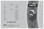
NOT FOR HOME USE
Owner’s Manual For:
PORTABLE POWER SAW
MODEL 400
Table Of Contents: . . . . . . . . . . . . . . . . . . . . . . . . . . . . . . . . . . . . . . . . . Page
•Notice to Employer and Safety Director . . . . . . . . . . . . . . . . . . . . . . . . . . 2
•Notice to Operators, Maintenance and Cleanup Personnel . . . . . . . . . 3
•Parts Diagram . . . . . . . . . . . . . . . . . . . . . . . . . . . . . . . . . . . . . . . . . . . . . . . . 4
•Parts List . . . . . . . . . . . . . . . . . . . . . . . . . . . . . . . . . . . . . . . . . . . . . . . . . . . . 5
•Installation Instructions . . . . . . . . . . . . . . . . . . . . . . . . . . . . . . . . . . . . . . . . 6
•General Safety Instructions . . . . . . . . . . . . . . . . . . . . . . . . . . . . . . . . . . . . . 7
•Operation Instructions . . . . . . . . . . . . . . . . . . . . . . . . . . . . . . . . . . . . . . . . . 8
•Maintenance Instructions . . . . . . . . . . . . . . . . . . . . . . . . . . . . . . . . . . . . . . 10
JARVIS
6205005:::.
®
PRODUCTS CORPORATION
33 ANDERSON ROAD, MIDDLETOWN, CONNECTICUT 06457--4926
UNITED STATES OF AMERICA
FAX 860--347--6978
E--MAIL. [email protected]
TEL. 860--347--7271
WWW. jarvisproducts.com
notice to employer
and safety director
MODEL 400
pg 2 of 12
Keep hands clear.
NOTICE TO EMPLOYER AND SAFETY DIRECTOR
AVOID INJURY
1. Remove and repair any tool that malfunctions. All personnel must be instructed to remove any
malfunctioning equipment.
2. Ensure that all employees who use this tool are trained in the proper use of this tool and are aware
of the dangers that may arise if they do not follow the procedures outlined in this brochure.
3. Enclosed are four (4) copies of “NOTICE TO OPERATORS, MAINTENANCE AND CLEANUP PERSONNEL.” Post one copy on the employees’ bulletin board; give one copy to operator(s);
give one copy to the maintenance foreman; and give one copy to the sub-contract cleanup / internal
cleanup foreman. Additional copies will be provided upon request.
4. The tool is designed and intended to be powerful. That fact should be obvious to your employees,
but you must emphasize it to them.
5. Never make modifications or alterations to the tool. Replace any missing or illegible labels.
6. Always disconnect the tool from its power supply when it is not in use.
7. Follow our installation and maintenance instructions for proper installation and care of the tool.
8. Ensure that employees wear eye protection in accordance with OSHA’s eye and face protection requirements (29 CFR 1910.133) at all times.
9. Hand/Wrist/Arm injury and other Cumulative Trauma Disorders may result from repetitive work,
motion or vibration. You must make your employees aware of hazards, symptoms of injury and appropriate prevention. See OSHA’s “Ergonomics Program Management Guidelines for Meatpacking
Plants.”
10. Avoid injury. Do not permit the tool to be misused.
11. If you resell or distribute a Jarvis product, you must provide the purchaser with the appropriate safety sheets and tool brochure. Additional copies of safety sheets and tool brochures will be provided
upon request.
JARVIS
6205005:::.
®
PRODUCTS CORPORATION
33 ANDERSON ROAD, MIDDLETOWN, CONNECTICUT 06457--4926
UNITED STATES OF AMERICA
FAX 860--347--6978
E--MAIL. [email protected]
TEL. 860--347--7271
WWW. jarvisproducts.com
notice to operators, maintenance
and cleanup personnel
MODEL 400
pg 3 of 12
Keep hands clear.
NOTICE TO OPERATORS, MAINTENANCE AND CLEANUP PERSONNEL
REMOVE ANY MALFUNCTIONING TOOL FROM SERVICE
REPORT ANY PROBLEMS TO YOUR SUPERVISOR
1. Always wear eye protection in accordance with OSHA’s eye and face protection requirements (29
CFR 1910.133), and when needed, a dust mask.
2. Do not operate near flammable liquids or in gaseous atmospheres.
3. Do not operate in outdoor locations or in damp or wet locations.
4. Do not overreach; keep proper footing and balance when using the tool.
5. Disconnect the power supply in accordance with OSHA’s lockout/tagout procedures (29 CFR
1910.147) before changing the blade.
6. Disconnect the power supply in accordance with OSHA’s lockout/tagout procedures (29 CFR
1910.147) before performing any repair or maintenance.
7. Disconnect the power supply -- or have the power supply disconnected -- in accordance with OSHA’s
lockout/tagout procedures (29 CFR 1910.147) before performing any cleanup.
8. Disconnect the power supply when the tool is not in use.
9. Never put fingers, hands or other parts of the body on the cutting edge of the blade or in the cutting
path.
10. Test the tool prior to use or daily. Depress the trigger and the tool should start. Release the trigger
and the tool should stop. If the tool malfunctions, remove it from service and report or repair it immediately.
11. Never depress the trigger unless you are going to use or test the tool.
12. Never make any alterations to the tool. Report or replace any missing or illegible labels.
13. Always use both hands when starting and operating the tool to avoid the risk of possible “kick back”
or “recoil.” Continue holding the tool with both hands until the saw blade comes to a complete stop.
JARVIS
6205005:::.
®
PRODUCTS CORPORATION
33 ANDERSON ROAD, MIDDLETOWN, CONNECTICUT 06457--4926
UNITED STATES OF AMERICA
FAX 860--347--6978
E--MAIL. [email protected]
TEL. 860--347--7271
WWW. jarvisproducts.com
parts diagram
MODEL 400
JARVIS
6205005:::.
pg 4 of 12
®
PRODUCTS CORPORATION
33 ANDERSON ROAD, MIDDLETOWN, CONNECTICUT 06457--4926
UNITED STATES OF AMERICA
FAX 860--347--6978
E--MAIL. [email protected]
TEL. 860--347--7271
WWW. jarvisproducts.com
parts list
MODEL 400
pg 5 of 12
IT.
1
2
3
4
5
6
7
8
9
10
11
12
13
14
15
16
17
18
19
20
21
22
23
24
25
26
27
28
29
30
31
32
33
34
35
36
37
38
39
40
41
42
43
44
45
46
47
48
49
OLD
JARVIS
PART NO. PART NO.
1063112 501022--005
1063111 501022--004
1063110 501022--003
1015006 501174
1002191 501002
1055428 100101--004
1055427 100101--002
1021215 100243--003
1063119 501224--003
1063120 501224--004
1027040 501021
1007164 100105--001
1063117 501224--001
1063118 501224--002
1026072 501225
1021227 100422--004
1035193 501120--001
1035192 501103
1036116 501171
1036117 501186
1027041 501046
3065009 501058
8030031 100099--001
1002192 501003
1007162 100022--006
1055439 100102--002
1054076 501380
1002203 501004--002
1005038 100739--001
1055454
1055438 100101--003
1012046 501042
1012047 501043
1027048 501272
1036120 501273
1055424 100035--002
1017030 501023
1017031 501084
1017052
1017235
1054173
1045013 100131--001
1004149 100426--001
1021218 100425--001
1027043 501081
3026024 501223
1020133 501377
1035191 501008
1002193 501005
1055452
1055426 100101--001
3028030 501053
1029185 501082
1013310 100069--013
1021216 100424--001
3001008 501337
3001011 501337
1063125 501294
1013137 501295
PART NAME
QTY
Brush Cap
2
Brush and Spring
2
Brush Holder
2
Deflector
2
Top Cap
1
Screw, Flat Head Phil
4
Screw, Set of 12
Ball Bearing
1
Stator 115V
1
Stator 230V
1
Stator Stud
2
Locknut
4
Armature 115V
1
Armature 230V
1
Pinion Gear
1
Ball Bearing
1
Seal
1
Seal
1
Bushing
1
Bushing Spacer
1
Rod Stud
1
Push Rod and Stud
1
Hex Key
1
Blade Support Clamp
1
Cap Nut
6
Screw
2
Coated Screw
3
Handle Cover
1
Switch
1
Screw, Round Head
3
Screw, Set of 12
”S” Clip
1
“U” Clip (rubber)
1
Stud
3
Insert
3
Set Screw
1
Info Label 115V, English 1
Info Label 230V, English 1
Info Label 115V, French 1
Info Label 230V, French 1
Label Retaining Screw
4
Label Retaining Rivet
4
Thrust Bearing Race
1
Needle Thrust Bearing
1
Drive Stud
1
Gear and Drive Stud
1
Gear Stud
1
Gasket
1
Bottom Plate
1
Screw, Flat Head Phil
4
Screw, Set of 12
Connect. Rod & Brg
1
Spacer
1
Snap Ring
1
Needle Bearing
2
Cord and Plug 115V
1
Cord and Plug 230V
1
Strain Relief
1
Clamp Ring
1
JARVIS
6205005:::.
®
JARVIS
IT. PART NO.
50 1063109
51 1016213
52 1007166
53 1055429
54 1006021
55 1027042
OLD
PART NO.
100647
501001--005
501376
100102--003
501066
501065
PART NAME
Grommet
Housing
Gear Stud Nut
Screw
Knob
Handle Stud
QTY
1
1
1
2
1
1
blades, blade supports
and accessories
IT.
56
57
58
59
60
JARVIS
PART
NO.
1058065
1058069
1058066
1058097
1023122
1023121
1023125
1023126
1023127
1023128
1023129
1023166
1023120
3058037
OLD
PART
NO.
501007T
501071
501058T
PART NAME
QTY
Blade Support 8 inch
1
Blade Sup. 8” depth gage 1
Blade Support 16 inch
1
Blade Support 24 inch
1
501246
Blade, 8 inch (4 TPI)
1
501247
Blade, 16 inch (4 TPI)
1
501104
Blade 8 inch (8 TPI)
1
501108
Blade 8 inch (12 TPI)
1
501116
Blade 16 inch (8 TPI)
1
501151
Blade 8 inch (knife)
1
501155
Blade 16 inch (knife)
1
Blade 24 inch (knife)
1
501121
Blade 16 inch (combo)
1
501352--002 Depth Gage Assembly
replacement kits
JARVIS
OLD
PART
PART
NO.
NO.
IT.
PART NAME
3063010 501351--001 Armature & Bearing
without Pinion Gear 115V
3063011 501351--002 Armature & Bearing
without Pinion Gear 230V
3063007 501235--001 Armature & Bearing
with Pinion Gear 115V
3063008 501235--002 Armature & Bearing
with Pinion Gear 230V
3063013 501232
Armature & Pinion 115V
3063014 501233
Armature & Pinion 230V
3001008 501006
Cord Assembly 115V
3001010 501089
Cord Assembly 230V
3026023 501088
Gear & Bearing Assembly
3016118 501168--001 Housing, Seals & Bushing
PRODUCTS CORPORATION
33 ANDERSON ROAD, MIDDLETOWN, CONNECTICUT 06457--4926
UNITED STATES OF AMERICA
FAX 860--347--6978
E--MAIL. [email protected]
TEL. 860--347--7271
WWW. jarvisproducts.com
installation instructions
MODEL 400
pg 6 of 12
SPECIFICATIONS
Motor Power
Operating Volt/Amp
wire to a live terminal. If your Jarvis Wellsaw is the 115
1 hp
745 W
volt model, it has a plug that looks like figure ”A”. If
230V/7.5A, 1 phase, 50/60 Hz
115V/15A, 1 phase, 50/60 Hz
your Jarvis Wellsaw is the 230 volt model, it has a plug
Stroke
1.13 in
Blade Speed
Control Handle
29 mm
8000 strokes / min
Single Trigger
Electric
Blade Length
8 in
16 in
203 mm
406 mm
Overall Length (16 in blade)
32 in
813 mm
9.8 lbs
4.5 kg
Weight (without blade)
that looks like figure ”B”.
figure A
figure B
grounding blade
grounding blade
Do not use any adapters with the Jarvis Wellsaw
INSTALLATION INSTRUCTIONS
These instructions have been prepared to assure you of
satisfactory operation through proper use of your Jarvis
Wellsaw.
Read them carefully and keep them for future reference.
POWER SUPPLY
Your Jarvis Wellsaw operates on 50 or 60 Hz., single
phase alternating current. Its voltage rating is indicated
on the name plate (either 115 or 230 Volt). If an extension cord is to be used, be sure that the wire size is adequate to maintain full line voltage to the tool.
EXTENSION CORDS
Make sure your extension cord is in good condition.
When using an extension cord, be sure to use one heavy
enough to carry the current your Jarvis Wellsaw will
draw. An undersized cord will cause a drop in line voltage resulting in loss of power and overheating. The table
below shows the correct size to use depending on cord
length and nameplate ampere rating. If in doubt, use the
next heavier gage. The smaller the gage number, the
heavier the cord.
Minimum Wire Gage for Extension Cords
Volts
Total Length of Cord in Feet
120
240
GROUNDING
Your Jarvis Wellsaw should be grounded to prevent the
user from electric shock or electrocution. The Jarvis
Wellsaw is equipped with an approved three conductor
0--25
0--50
Amp Rating
0--6
6--10
26--50
51--100
51--100 101--150
101--200 201--300
Wire Size (AWG)
18
18
16
16
16
14
14
12
cord and three prong grounding--type plug to fit the proper grounding--type receptacle. The green conductor in
the cord is the grounding wire. Never connect the green
JARVIS
6205005:::.
®
When tool is used outdoors, use only extension cords labeled for outdoor use.
PRODUCTS CORPORATION
33 ANDERSON ROAD, MIDDLETOWN, CONNECTICUT 06457--4926
UNITED STATES OF AMERICA
FAX 860--347--6978
E--MAIL. [email protected]
TEL. 860--347--7271
WWW. jarvisproducts.com
general safety instructions
MODEL 400
pg 7 of 12
GENERAL SAFETY INSTRUCTIONS
For Operators, Employers and Maintenance Personnel
WARNING: When using electric tools, basic safety precautions should always be followed to
reduce the risk of fire, electric shock and personal injury, including the following:
Working Precautions:
1. READ ALL INSTRUCTIONS.
• Know your Jarvis Wellsaw and understand safety notices, manuals and instructions
in the literature provided. Become familiar with the Jarvis Wellsaw, its dangers,
limitations and applications.
2. INSTALL THE TOOL PROPERLY.
• Ground the tool. See instructions provided in the installation section of this manual.
• Use the proper extension cord. See instructions provided in the installation section of this
manual.
3. USE THE RIGHT TOOL AND ATTACHMENTS.
• Select the proper tool to do the job. The Jarvis Wellsaw is designed for meat and bone
cutting; wood cutting; non--woven and geo--textile cutting. Do not use the Jarvis Wellsaw
for non--intended purposes.
4. KEEP WORK AREAS CLEAN AND WELL LIT.
• Cluttered, oily and poorly lit work areas invite accidents.
• Keep visitors a safe distance from the work areas.
5. AVOID DANGEROUS ENVIRONMENTS.
• Do not expose the power tool to rain.
• Do not use the tool in presence of flammable liquids or gases.
6. WEAR PROPER APPAREL.
• Avoid being pulled by moving parts of the Jarvis Wellsaw. Do not wear loose clothing or
dangling objects. Restrain long hair.
• Wear safety glasses when operating the tool.
7. MAINTAIN THE JARVIS WELLSAW AND ACCESSORIES WITH CARE.
• Keep the Jarvis Wellsaw sharp and clean for the best and safest performance.
• Follow the instructions for lubricating and changing the blades.
• Inspect the Jarvis Wellsaw regularly. If the Jarvis Wellsaw is malfunctioning, remove it
from service and report any problems to your supervisor immediately.
• Keep the handles dry, clean and free from oil and grease.
8. STAY ALERT.
• Watch what you are doing and use common sense.
9. SAVE THESE INSTRUCTIONS.
JARVIS
6205005:::.
®
PRODUCTS CORPORATION
33 ANDERSON ROAD, MIDDLETOWN, CONNECTICUT 06457--4926
UNITED STATES OF AMERICA
FAX 860--347--6978
E--MAIL. [email protected]
TEL. 860--347--7271
WWW. jarvisproducts.com
operation instructions
MODEL 400
pg 8 of 12
OPERATION INSTRUCTIONS
B. LARGE CROSS SECTIONS:
Before starting regular operation of the Jarvis Wellsaw,
we recommend that you make a few cuts with a fine pitch
blade to acquaint yourself with the operation of the tool
before using any of the coarser blades.
1. Rocking the saw in the cut will speed up the cutting action. An 8--tooth blade is recommended.
C. SINKING THE BLADE THROUGH A SURFACE:
A. AVERAGE CUTTING AND RIPPING:
1. Place your work piece on a solid support at a
convenient working height.
2. Adjust the material so that the line of cut will be
close to the support. Secure it firmly.
1. Your power hand saw is not designed for regular
use in starting its own hole by sinking blades
through a surface, commonly called “plunge
cutting”. If attempted, the operator must:
a. Keep the saw blade as parallel to the work
as possible.
3. To prevent starting torque of the motor from
pulling the saw away from line of cut, the operator should make a few short strokes until the
blade has cut into the material about 1/4 inch before squeezing trigger switch.
b. Immediately, as the blade makes contact
with the work piece, start to draw the saw
back slowly from the starting point.
c. Repeat the operation outlined in “b”, if necessary.
4. Both hands should be on the saw at all times
while cutting. Continue holding the tool with
both hands until the saw blade comes to a
complete stop.
d. Have room to draw the saw at least 4--6 inches before cutting through a 1 inch thickness.
5. The saw should be kept at a 90 degree angle to
the work piece while cutting material that is
thicker then 1 inch. For thin materials a 12-tooth blade and a 30 degree cutting angle are recommended.
e. Do not force the saw blade, but keep it
moving slowly on the draw back from the
starting point. After the break through cut
has been made and the end of the blade support extends through the material at least
1--1/2 inches, the saw may be tipped to a
normal cutting angle.
6. The saw should be pushed firmly into the material while cutting.
7. Do not allow the saw blade or the blade support
to leave the work piece while cutting.
8. Never allow the saw blade to float into material
while cutting.
9. Never permit any part of the saw, except the
blade or the blade support, to contact the work
piece during the cut.
JARVIS
6205005:::.
®
D. NOT FOR CUTTING METAL:
1. Due to the blade speed and design, your Jarvis
Wellsaw is not for cutting metal.
E. NOT FOR CUTTING SMALL RADII:
PRODUCTS CORPORATION
33 ANDERSON ROAD, MIDDLETOWN, CONNECTICUT 06457--4926
UNITED STATES OF AMERICA
FAX 860--347--6978
E--MAIL. [email protected]
TEL. 860--347--7271
WWW. jarvisproducts.com
operation instructions
MODEL 400
pg 9 of 12
F. HEAVY AND CONTINUOUS WOOD CUTTING:
SAW:
1. For heavy or continuous wood cutting, lubricate
the blade grove with oil or Jarvis Wellsaw lubricant 1062023.
2. When cutting wet or gummy wood or other material where there is a tendency for a deposit to
build up on the sides of the blades, use a 50--50
mixture of kerosene and lubricating oil and
place it on the sides of the blade and the blade
support.
JARVIS
6205005:::.
G. ALWAYS KEEP A SHARP BLADE ON THE
®
1. Cutting with a dull or badly worn blade can
overload the saw and cause damage from overheating.
2. New blades can be purchased from Jarvis.
PRODUCTS CORPORATION
33 ANDERSON ROAD, MIDDLETOWN, CONNECTICUT 06457--4926
UNITED STATES OF AMERICA
FAX 860--347--6978
E--MAIL. [email protected]
TEL. 860--347--7271
WWW. jarvisproducts.com
maintenance instructions
MODEL 400
pg 10 of 12
MAINTENANCE INSTRUCTIONS
7. Install handle stud (item 55) using two larger
phillips screws (item 53).
Always disconnect the saw from its power supply
before performing any maintenance.
NOTE: Your Jarvis Wellsaw is equipped with a
Item numbers: refer to the parts diagram on page 4.
hex key (item 20) for removing the blade. This
wrench is located in the housing directly behind
A. LUBRICATION:
1. The gear case should be kept 1/3 full of grease.
To check the grease level, remove the bottom
plate (item 41) and its gasket (item 40). It should
be checked every thirty days for saws that are
used moderately and every two weeks for saws
that are used daily. If replacement grease is required it should be obtained from Jarvis.
1. Tap (3) inserts (item 31) gently into the bores on
blade support clamp (item 21).
2. Align the blade support clamp onto saw housing
(item 51), making sure the inserts stay in place.
3. Assemble (3) studs (item 30) with cap nuts (item
22) and place them through the saw housing and
the blade support clamp.
4. Draw down all (3) cap nuts evenly until the inserts are bottomed out into the saw housing.
5. Remove the cap nuts and the blade support
clamp. The inserts should now be properly set
into the saw housing.
6. Assemble blade support (item 56) over the inserts on the saw housing. Place the blade support clamp on the saw housing and fasten with
the studs, the cap nuts and phillips screws (item
23).
6205005:::.
®
the blade support knob (item 54).
1. Insert the hex key through the hole in the outer
end of blade (item 57, 58 or 59) and pull the
blade to the outer end of the stroke.
2. Loosen the blade holding set screw (item 32)
about 1/2 turn. The set screw must be loosened
through the hole in the housing.
3. Reinsert the hex key in the hole at the outer end
of the blade and pull the blade out.
B. BLADE SUPPORT INSTALLATION:
JARVIS
C. BLADE REMOVAL:
D. BLADE INSTALLATION:
1. Insert hex key (item 20) into set screw (item 32).
2. Fasten the set screw (through the hole in housing) into the hole in the end of push rod (item
19). The hole in the housing must be aligned
with the hole in the push rod for the set screw to
be fastened. (It may be necessary to turn the armature fan to adjust the push rod properly). Do
not tighten.
3. Align blade (item 57, 58 or 59) with blade support (item 56). The blade should extend approximately 3 inches from the end of the blade support.
4. Slide the blade onto the blade support until the
crimp in the blade is touching the end of the
blade support.
PRODUCTS CORPORATION
33 ANDERSON ROAD, MIDDLETOWN, CONNECTICUT 06457--4926
UNITED STATES OF AMERICA
FAX 860--347--6978
E--MAIL. [email protected]
TEL. 860--347--7271
WWW. jarvisproducts.com
maintenance instructions
MODEL 400
pg 11 of 12
5. Use a rubber hammer and tap the end of blade towards the body of the saw until the crimp in the
blade slides into the slot in the blade support.
6. Slide the blade into the push rod as far as it will
go.
7. Tighten set screw (item 32) with the hex key.
The set screw must be fully tightened before
running the saw or damage to the saw will occur.
E. GENERAL DISASSEMBLY:
1. Remove blade (item 57, 58 or 59) and blade support (item 56).
2. Remove handle cover (item 25).
3. Remove switch (item 26). Remove the top two
wires by inserting a 1/16 inch diameter pin
punch directly adjacent to the stator wires.
4. Remove brush cap (item 1) and brushes (item 2).
8. Remove bottom plate (item 41) and gasket (item
40).
9. Insert a small block of wood between the connecting rod (item 43) and the housing (item 51)
to stop the rotation of the connecting rod. Remove lock nuts (item 10). Remove the connecting rod.
10. Using a 5/16 inch hex key, loosen gear stud (item
39) -- left hand thread. Be sure not to spin gear
stud nut (item 52). Remove items 35--39, 45 and
46.
11. Remove the push rod and stud (item 19) through
the center of the housing.
12. Clean the gear housing cavity to remove any
contaminated lubricant.
13. Remove and replace any faulty parts and reassemble by reversing these steps.
NOTE (when reassembling):
5. Remove deflectors (item 4).
6. Remove top cap (item 5) -- stator (item 8) will
be attached.
7. Remove armature (item 11). Hold the armature
in one hand and tap housing (item 51) with a rubber hammer with the other hand to loosen the armature. (Pinion gear -- item 12 -- on armature
has a left hand thread).
JARVIS
6205005:::.
®
a. Step 10: Use Loctite 271 on gear stud nut
(item 52) before fastening gear stud (item
39).
b. Step 7: Reassemble armature (item 11) in
housing (item 51) by using a center punch
to tap the armature until its bearing is fully
seated.
PRODUCTS CORPORATION
33 ANDERSON ROAD, MIDDLETOWN, CONNECTICUT 06457--4926
UNITED STATES OF AMERICA
FAX 860--347--6978
E--MAIL. [email protected]
TEL. 860--347--7271
WWW. jarvisproducts.com
MODEL 400
pg 12 of 12
GENERAL SAFETY INSTRUCTIONS
For Operators, Employers and Maintenance Personnel
READ ALL INSTRUCTIONS BEFORE USING TOOL AND SAVE THEM FOR FUTURE REFERENCE
ATTENTION: When using electric tools, basic safety precautions should always be followed to reduce
the risk of potentially dangerous tools and personal injury, including the following:
Working Precautions:
1. KNOW YOUR JARVIS WELLSAW.
• Read and understand safety notices, manuals and instructions on the Jarvis Wellsaw in
the literature provided. Become familiar with the Jarvis Wellsaw, its dangers, limitations
and applications.
2. USE THE RIGHT TOOL AND ATTACHMENTS.
• Select the proper tool to do the job. The Jarvis Wellsaw is designed for meat and bone
cutting; wood cutting; non--woven and geo--textile cutting. Do not use the Jarvis Wellsaw
for non--intended purposes.
3. KEEP WORK AREAS CLEAN AND WELL LIT.
• Cluttered, oily and poorly lit work areas invite accidents.
• Keep visitors a safe distance from the work areas.
4. AVOID DANGEROUS ENVIRONMENTS.
• Do not expose the power tool to rain.
• Do not use the tool in presence of flammable liquids or gases.
5. WEAR PROPER APPAREL.
• Avoid being pulled by moving parts of the Jarvis Wellsaw. Do not wear loose clothing or
dangling objects. Restrain long hair.
6. MAINTAIN THE JARVIS WELLSAW AND ACCESSORIES WITH CARE.
• Keep the Jarvis Wellsaw sharp and clean for the best and safest performance.
• Follow the instructions for lubricating and changing the blades.
• Inspect the Jarvis Wellsaw regularly. If the Jarvis Wellsaw is malfunctioning, remove it
from service and report any problems to your supervisor.
• Keep the handles dry, clean and free from oil and grease.
7. STAY ALERT.
• Watch what you are doing and use common sense.
PRODUCTS CORPORATION
JARVIS
JARVIS
CORPORATION
PRODUCTS
CORPORATION
® ® PRODUCTS
33 ANDERSON ROAD, MIDDLETOWN, CONNECTICUT 06457--4926
6205005:::.
6205005:::.
33 ANDERSON ROAD, MIDDLETOWN, CONNECTICUT 06457--4926
UNITEDUNITED
STATESSTATES
OF AMERICA
E--MAIL.E--MAIL.
[email protected]
OF AMERICA
[email protected]
FAX 860--347--6978
TEL. 860--347--7271
WWW. jarvisproducts.com
FAX 860--347--6978
TEL. 860--347--7271
WWW. jarvisproducts.com