1
SysLINK
Administrator's
Guide
SYSTECH
C O R P O R A T I O N
Document number 80-001113
Revision A
Created 2012, and Protected Under the U.S. Copyright Act of 1976.
Copyright © 2012, SYSTECH Corporation
All Rights Reserved
This document is subject to change without notice.
Table of Contents
CHAPTER 1: INTRODUCTION .................................................................................. 3
CHAPTER 2: CONFIGURATION................................................................................ 5
Gateway Configuration ................................................................................................... 5
Setting the IP Address .................................................................................................... 5
DHCP/BOOTP.............................................................................................................. 5
Port Server Utility ......................................................................................................... 5
How to Use the Ports ...................................................................................................... 6
Configuring Dial to IP on Terminal Ports ...................................................................... 6
Configuring Modem Emulation on a Serial Port ............................................................ 7
Configuring Outgoing Network Connections on a Serial Port ....................................... 7
Configuring Incoming Network Connections via Telnet Server ..................................... 8
Configuration via the Web Browser Interface ............................................................... 9
Serial Settings ............................................................................................................ 10
Port Services .............................................................................................................. 12
Service Types .........................................................................................................................14
No Outgoing Service ....................................................................................................................... 14
Modem Service ............................................................................................................................... 14
Outgoing Network Connection ........................................................................................................ 16
Outgoing Telnet Connection ........................................................................................................... 16
Network Connection Options........................................................................................................... 16
Telnet Options ................................................................................................................................. 17
Remote Port Access........................................................................................................................ 18
Phone Number Translation ......................................................................................... 19
Network Translation ................................................................................................... 21
Protocol Settings ........................................................................................................ 22
Raw or Secure TCP ................................................................................................................23
(Secured) Simple POS Terminal Protocols .............................................................................24
(Secured) Converted POS Terminal Protocols .......................................................................25
SSL Options ............................................................................................................................28
Type of Peer............................................................................................................................28
Peer Identity Verification .........................................................................................................28
List of Allowable Ciphers .........................................................................................................29
Network Settings ........................................................................................................ 31
IPv4 Address ...........................................................................................................................31
IPv4 Netmask ..........................................................................................................................31
Default Gateway......................................................................................................................32
Ethernet MTU ..........................................................................................................................32
TCP Keep-Alive.......................................................................................................................33
HTTP Server Configuration .....................................................................................................33
Remote Management..............................................................................................................34
DNS Settings .............................................................................................................. 35
IP Routing .................................................................................................................. 37
PPP Settings .............................................................................................................. 39
Time Settings ............................................................................................................. 41
Security Settings ........................................................................................................ 43
System Password ...................................................................................................................43
Network Isolation Configuration ..............................................................................................44
Security Log ............................................................................................................................45
SSL Security Certificates ............................................................................................ 46
Online Update ............................................................................................................ 48
Lightweight Heartbeat Settings ................................................................................... 52
Cellular Settings ......................................................................................................... 54
DHCP Server Management ........................................................................................ 55
Accessing the Gateway from a Remote Network ....................................................... 56
CHAPTER 3: TROUBLESHOOTING AND UPDATING ........................................... 57
Troubleshooting ............................................................................................................ 58
Serious System Error Codes ...................................................................................... 60
Port Status ..................................................................................................................... 61
OS and Network Information........................................................................................ 63
Temperature Monitor Settings ..................................................................................... 63
Motion Detection Settings ............................................................................................ 64
Log/Debug Settings ...................................................................................................... 65
Ping ................................................................................................................................ 67
Reset/Reboot ................................................................................................................. 68
Flash Management ........................................................................................................ 69
Flash Update .............................................................................................................. 70
Download Flash Information ....................................................................................... 70
Restore Factory Defaults ............................................................................................ 71
PDA Compaction ........................................................................................................ 71
Other Debugging ........................................................................................................... 72
CHAPTER 4: MODEM EMULATION ........................................................................ 73
Modes ............................................................................................................................ 73
Escape Sequence.......................................................................................................... 73
Types of TCP/IP connections ....................................................................................... 73
Outgoing and Incoming Calls ...................................................................................... 74
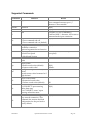
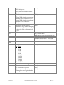
AT Commands ............................................................................................................... 74
Supported Commands................................................................................................ 75
S-Registers .................................................................................................................... 77
Supported S-registers ................................................................................................ 77
Response Codes ........................................................................................................... 77
Modem Signal Behavior ............................................................................................... 78
Phone Numbers ............................................................................................................ 79
Port Settings ................................................................................................................. 79
CHAPTER 5: LICENSE AND COPYRIGHT INFORMATION ................................... 80
INDEX ................................................................................................... 83
Chapter 1: Introduction
The Systech family of SysLINK devices enables secure communication among a wide variety
of wired and wireless devices and Internet connectivity via Wi-Fi, Ethernet, and cellular
connections. Key applications include secure cellular and Internet access for ATM payment
processing; vending machine telemetry and payment processing; POS payment processing
and internet connectivity; remote information display; and kiosk internet connectivity. The
SysLINK family also supports home and building security and automation applications, and
mobile health.
The SysLINK gateway family provides communication between a variety of local devices
and computers connected to a network – either a private network or the Internet. Local
devices may have dial, serial, Ethernet, or wireless (Wi-Fi, Zigbee, Z-Wave, or Bluetooth)
interfaces. The connection to network may be Ethernet, Cellular, Wi-Fi or dial.
When a SysLINK unit is connected to your LAN and to one or more devices, it manages
device traffic over the network, routing it to/from the correct host. The SysLINK may have
terminal (phone line) ports and/or serial ports that emulate external modems.
As system administrator, you will have responsibility for setting up and configuring the
gateway to meet your usage requirements. The gateway has been designed to make your job
easy. The hardware is simple to install, and a browser interface ensures that management is
just as simple. In addition to configuration tools, the communications server provides tools
for monitoring and managing your port activity and for diagnosing and troubleshooting
system problems.
80-001113
SysLINK Administrator’s Guide
Page 3
Chapter 2: Configuration
Gateway Configuration
Before configuring the gateway, it must obtain an IP address as described below. After it
has an IP address, the gateway is configured primarily through the web browser interface.
Setting the IP Address
The factory default configuration for the gateway typically has no IP address. To use the
gateway you must assign it an IP address. There are several ways to do this. When the
gateway has a good IP address (that is, not temporary), the status light will blink green.
DHCP/BOOTP
If the gateway does not have an IP address, or if it obtained a temporary one via the method
described below, it will attempt to get one from a DHCP/BOOTP server on the local
network. If an IP address is obtained from a DHCP server, the gateway will also ask the
DHCP server for a subnet mask, a default gateway, an NTP time-server, and a DNS name
and server.
Port Server Utility
You can use the Systech Port Server Utility, or NCCTool to assign an IP address to your
gateway. Once you have done this, DHCP/BOOTP is disabled. The Port Server Utility
always uses the default subnet mask for the given IP address class. If you are subnetting
your network, the NCCTool allows you to override the default subnet mask.
80-001113
SysLINK Administrator’s Guide
Page 5
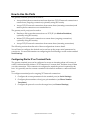
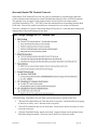
How to Use the Ports
The gateway terminal port(s) can be used to:
Accept dialed phone connections and turn them into TCP/IP network connections to
remote hosts (outgoing connections) optionally using SSL security
Accept TCP/IP network connections from remote hosts (incoming connections) and
make a phone connection to an attached device.
The gateway serial port(s) can be used to:
Emulate a dial-up modem connection over TCP/IP (via Modem Emulation)
optionally using SSL security
Initiate TCP/IP network connections to remote hosts (outgoing connections)
optionally using SSL security
Accept TCP/IP network connections from remote hosts (incoming connections)
The following sections describe each of these configurations in more detail.
You will need to configure the desired service and set up the proper serial parameters for
your device. For more information on configuring the serial settings, see the section entitled
Serial Settings.
Configuring Dial to IP on Terminal Ports
The gateway terminal ports can be configured to accept an incoming phone call, answer it
with it’s internal modem, initiate a TCP connection to a remote host, and then route all data
over this connection. This connection is configured to match the protocol required by the
host. It is generally used to connect a terminal with a built-in modem to a network-based
host.
To configure a terminal port for outgoing TCP network connections:
1. Configure the correct parameters for the terminal port (see Serial Settings)
2. Configure phone number to host/port pair translation (see Phone Number
Translation)
3. Configure the protocol to use for the target host (see Protocol Settings)
80-001113
SysLINK Administrator’s Guide
Page 6
Configuring Modem Emulation on a Serial Port
The gateway can be configured to allow legacy devices that interact with external modems
to communicate over a TCP/IP network instead of a phone line. When modem emulation is
enabled, the gateway will respond to AT commands generated by the attached device. After
receiving the dial command, the gateway will make a TCP connection to the specified host,
optionally translating the phone number into a TCP host and port. The gateway will also
accept incoming TCP/IP connections and generate the appropriate response codes. Each
Systech serial port accepts incoming TCP connections on two TCP ports: an 8000-series port
(for raw data), and a 9000-series port (for telnet data).
To enable modem emulation:
1. Configure the correct serial parameters on the serial port (see Serial Settings)
2. Enable modem emulation (see Port Services)
3. Optionally configure phone number to host/port pair translation (see Phone
Number Translation)
4. Configure connection protocols for the target host(s) (see Protocol Settings)
Once modem emulation is enabled, verify correct operation by connecting a terminal to the
appropriate serial port and issuing an 'AT' command. If the gateway returns the 'OK' result
code, modem emulation is now functioning properly. You may now establish an outgoing
connection with the 'ATD' command (see Phone Numbers for more information on IP
address formats).
Configuring Outgoing Network Connections on a Serial Port
The gateway can be configured to initiate TCP connections to remote hosts from a serial
port. This connection can be configured for a variety of host protocols. It is generally used
when the gateway must initiate the network connection to the remote host.
This option can provide telnet logins for terminals attached to the gateway, or it can
establish raw data paths for other serial devices. To configure a port for outgoing TCP
network connections:
1. Configure the correct serial parameters on the serial port (see Serial Settings)
2. Configure the desired TCP protocol parameters (see Port Services)
3. Configure connection protocols for the target host(s) (see Protocol Settings)
80-001113
SysLINK Administrator’s Guide
Page 7
Configuring Incoming Network Connections via Telnet Server
The gateway is pre-configured to accept incoming TCP connections from TCP socket-based
applications. Each Systech serial port accepts incoming TCP connections on two TCP ports:
an 8000-series port (for raw data), and a 9000-series port (for telnet data).
The 8000-series port (8001 for port 1, or 800N for port N) is a raw data path that passes all
data back and forth between the network and the serial device without further processing. It
should be used by applications that support simple TCP connections and do not implement
the telnet protocol. There is no protocol involved beyond TCP/IP.
The 9000-series port (9001 for port 1, or 900N for port N) implements the telnet protocol and
supports the following telnet options: SUPPRESS GOAHEAD, BINARY, ECHO, COMPORT-OPTION and TIMING MARK. It should be used by the Systech NativeCOM driver,
and by other applications that support telnet.
80-001113
SysLINK Administrator’s Guide
Page 8
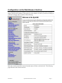
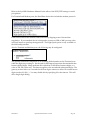
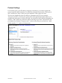
Configuration via the Web Browser Interface
Once the gateway has an IP address, you can use a web browser to monitor and configure it.
Simply specify the IP address of the gateway as the address or URL in your browser and you
will see a web page that is similar to the following:
Select the section you wish to access from the menu of links on the left side. The following
pages discuss each of these sections.
80-001113
SysLINK Administrator’s Guide
Page 9
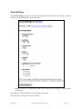
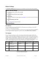
Serial Settings
The Serial Settings page allows you to specify the baud rate, character size, parity, stop bits,
and flow control behavior for each serial port:
NOTE: an RFC-2217 telnet client with COM-PORT-OPTION support overrides these
parameters.
Enabling flow control enables it on both input and output.
The default port settings are as shown above.
80-001113
SysLINK Administrator’s Guide
Page 10
Refer to the SysLINK Hardware Manual for the effect of the DCE/DTE settings on serial
port pinouts.
For Terminal and Modem ports, the Baud Rate choices also include the modem protocols.
FastConnect reduces the modem connection time by skipping some of the modem
negotiation. If your attached device is designed to connect at 1200 or 2400 you may often
use FastConnect to speed up the negotiation. The High-Speed option is only available on
the dial-backup modem.
Also for Terminal and Modem ports, the following may be configured:
The gateway detects the completion of an incoming dialed number on the Terminal ports
when the digits stop coming in. Set the end-of-dial timeout larger than the maximum time
between dialed digits. Many modems dial with about 70-100 msecs between digits, so a
value of 120-150 works well. The timeout applies to the second and subsequent digits. The
gateway waits a little over 2 seconds for the first digit to timeout to allow for external access
digits (such as 9,1-800…). You may disable this by specifying 0 for the timeout. This will
allow single digit dialing.
80-001113
SysLINK Administrator’s Guide
Page 11
Port Services
By default, all ports are configured to accept incoming TCP connections from TCP/telnet
clients and no outgoing service is configured. You may configure the ports to initiate
outgoing raw TCP (with or without SSL) or telnet connections to remote servers. In
addition, the modem emulation feature may be enabled to allow a serial port to mimic a
modem interface.
A note about port naming and numbering: the gateway ports are labeled “POS Serial” (1 and
2), “POS Terminal” (1, 2, 3 and 4), and “Modem”. In this manual and in the web
configuration screens the ports are referred to as Serial1, Serial2, Terminal1, Terminal2,
Terminal3, Terminal4 and Modem. For incoming connections, the ports are numbered as
follows:
Incoming
Telnet Port
Raw TCP
Port
Serial1
9001
8001
Serial2
9002
8002
Terminal1
9003
8003
Terminal2
9004
8004
Terminal3
9005
8005
Terminal4
9006
8006
Modem
9007
8007
Port
When using the modem service on a port, the phone number will be translated to a
host/port pair then a TCP connection will be established to the remote host.
When using outgoing connections on a port, the settings configured on the Serial Settings
page will be applied to the port, and a TCP connection will be established to the remote host.
If Require carrier/Generate hangups is set, the service will wait for the presence of the DCD
modem signal before connecting.
Once connected, data received on the port is sent to the remote server over the network
connection and data received on the network connection is sent out the port.
The following screen shot represents most of the options available for configuration.
Depending on the Service Type you have selected, not all of these options will be displayed.
80-001113
SysLINK Administrator’s Guide
Page 12
80-001113
SysLINK Administrator’s Guide
Page 13
Service Types
No Outgoing Service
Selecting this option disables outgoing port services on the specified port. Incoming
connections are still allowed. All Port Services options will reset to defaults.
Modem Service
Selecting this option on a Terminal (phone line) port will enable phone number translation
on that port.
Selecting this option on a serial port will enable modem emulation on both the incoming and
outgoing network connections. See Modem Emulation for details on commands and
responses.
In both cases, the target peer (specified in the Phone Number Translation table and
configured in the Protocol Settings page) determines the type of outgoing connection that
will be made.
When Modem Service is selected, you may also configure the Source TCP Port (see below)
and enable or disable automatically detecting the serial baud rate.
The gateway's Modem Emulation service on a serial port has the ability to automatically
detect when the baud rate of the attached device is different from the one configured on the
gateway serial port. In many cases, it is possible to guess the speed of the attached device
and to automatically switch the serial port to match that speed.
80-001113
SysLINK Administrator’s Guide
Page 14
In some instances this functionality can cause inappropriate baud rate changes to be made
that will cause communications to break down. Two additional settings may help prevent
inappropriate changes: “Make autobaud persistent” and “Autobaud Baud Rates”
Checking “Make autobaud persistent” causes the SysLINK to lock in the baud rate once it
has successfully detected it.
“Autobaud Baud Rates” allow you to limit the baud rates that the SysLINK will cycle
between during autobaud detection. This is particularly useful if you know that a device
uses a limited set of baud rates but may change between them during normal operation.
80-001113
SysLINK Administrator’s Guide
Page 15
Outgoing Network Connection
Selecting this option enables an outgoing connection to the specified host. The Network
Connection Options (below) identify the host.
Outgoing Telnet Connection
Selecting this option enables an outgoing telnet connection to the specified host. The
Network Connection Options identify the host and the
Telnet Options (below) configure the specific type of telnet connection.
Network Connection Options
Destination Hostname/IP Address
Specify the IP address or Host name of the remote host in the Destination IP Address field.
Destination TCP Port
Specify the destination TCP port. The default port for telnet servers is 23, but it is usually
different for other types of servers.
Source TCP Port
In most cases, the value used for the source port is arbitrary and you can leave this field set
to 0 for "any". However, if your server or firewall has specific requirements you may specify
an explicit source port number in the Source TCP Port field. If this port is not available
when the TCP service starts up, an error will occur and the TCP service will reset and try
again.
Require carrier/Generate hangups
If you have configured a serial port with an outgoing service, you may want to delay the
TCP connection establishment until an attached terminal is powered up or an attached dialin modem has received a call. In this case, select the Require carrier/Generate hangups
option. The TCP session will not begin until the gateway senses the presence of DTR (in
DCE mode) or DCD (in DTE mode) on the port and it will close the TCP session if
DTR/DCD is lost.
Telnet clients usually do not want the operation of the port to be affected by the presence,
absence, or loss of modem signals. You probably do not want this option selected for those
applications.
Restart Delay
The Restart Delay keeps the TCP service from constantly retrying if the remote host
becomes unavailable, or in the event of network errors or other unexpected situations.
80-001113
SysLINK Administrator’s Guide
Page 16
When the TCP session ends, it will pause for the number of seconds specified by the Restart
Delay. The default value (and minimum value) for the Restart Delay is 1 second.
Wait for Keyboard Hit
You may configure the TCP connection to wait for a “keyboard hit” before starting the TCP
session. Enabling this mode will display a message on the serial port (after DCD is present if
DCD is required to use the port) asking the user to type a character to begin the TCP session.
Telnet Options
The following options apply only if an Outgoing Telnet Connection is configured.
Telnet Mode
The TCP service can connect to a server using the telnet protocol in either Binary mode (8bit) or Human mode (7 bit, performs line and character processing for terminals). The telnet
client will negotiate telnet parameters with the remote telnet server. The parameters that it
will request are as follows:
Binary mode: DO BINARY, WILL BINARY
Human mode: DO SUPPRESS GOAHEAD, WILL SUPPRESS GOAHEAD
The gateway also supports the following telnet modes if negotiated by the remote telnet
server: ECHO, COM-PORT-OPTION, TERMINAL-TYPE, and TIMING MARK. (Note that
the gateway does not support local echo. However, it will accept a WILL ECHO request for
remote echoing and will respond with DO ECHO.)
Terminal Type
If the remote host requests the DO-TERMINAL-TYPE telnet option, and the Terminal Type
field is configured, the gateway will respond with this value. This field is useful when you
are connecting serial terminals to the gateway and the remote host needs to know how to
format output to the terminal. Otherwise, you can leave this blank.
Quiet Mode
By default, the telnet session will display various status messages as it makes, loses, or
breaks connections to the remote server. Selecting Quiet Mode will suppress these
messages. This is useful when using serial devices that may be confused by these status
messages.
Telnet Escape Character
When the telnet client is in the 7-bit “Telnet mode”, it parses serial input for a special escape
character. The default escape character is “CTRL-]” (or ASCII 29). If it sees this character, it
breaks into the telnet command mode and displays a command prompt that allows the user
to execute some telnet session commands. You may specify a different character (as decimal
ASCII) to use as the Telnet Escape Character, or specify -1 to disable this feature entirely.
80-001113
SysLINK Administrator’s Guide
Page 17
Remote Port Access
Remote Port Access (RPA) allows a unit to make an outbound connection to a server to
allow that server, or a client that connects to that server, to access a port.
You may define RPA service on a port but not enable it. Then use LWHB to enable RPA
dynamically.
80-001113
SysLINK Administrator’s Guide
Page 18
Phone Number Translation
This table can be used to translate phone numbers into IP addresses or Hostnames. If an
attached device dials one of the specified telephone numbers, the corresponding IP address
and port are used to make the TCP connection. Note that all non-numeric characters except
the “,” (comma) in the phone number are ignored.
Terminal ports detect the dialed numbers from the DTMF tones generated by the attached
device. Serial ports, when modem emulation is enabled, detect the phone number from
ATD commands. Although the IP address of the remote host can be embedded directly into
the ATD command, certain devices can't always be easily configured to do this.
The Default Translation entry is used if the dialed phone number is not found in the list. If
there is no default entry, then the call will be routed to the modem (dial-backup) port, if
present.
The dial backup port will also be used if the host associated with a given phone number is
not available. In this case, by default, the modem will dial the same number that came in the
port. However, you may specify a Dialout Phone Number to be used on dial backup
instead.
The phone number table has a number of features to ease initial configuration. When an
attached device dials a number that is not in the table, the gateway creates a dummy entry in
the table. This entry will consist of just the phone number. Until you fill in the remainder of
the entry (IP Address/Hostname and Port) this entry will not be used.
80-001113
SysLINK Administrator’s Guide
Page 19
Once you have created an entry in the table, a link to the associated entry on the Protocol
Settings page appears on the right. If the protocol is not yet defined, this link, “Define
protocol”, will create a new entry on the Protocol Settings page, otherwise the link will be
“Edit protocol”.
The translation table screen allows you to add up to 5 new entries at a time. A total of 256
entries may be configured including the default entry.
In the example above, if the attached device dials 18005551212, the port will be connected to
the host at 192.168.1.100 on TCP port 5004. This host is not yet defined, so it will use the
default TCP protocol. If that host is not available, the dial backup port will dial 1-800-5555555. If the attached device dials any other number, the port will be connected to
host.testloc.com:5003, whose protocol is defined. And the terminal has actually dialed 5551212, generating an automatic, but not yet saved, entry.
80-001113
SysLINK Administrator’s Guide
Page 20
Network Translation
The gateway is capable of accepting incoming TCP connections and redirecting them to
remote TCP hosts. This functionality is called network translation and behaves much like a
TCP "pipe" between two systems.
It is also possible to modify the network protocol traveling through the TCP pipe by using
the Protocol Settings page to define the remote host's protocol requirements. The most
common use for this functionality is to add SSL encryption to an incoming TCP connection
prior to sending it along to the remote host.
The Network Translation table is used to define network mappings for TCP pipes. You must
first specify the incoming TCP port to which your device or application will connect. Then,
you must specify the outgoing hostname and destination TCP port for the TCP pipe.
You may also specify the source TCP port for the outgoing TCP connection. Usually, this
should be set to 0 to allow automatic selection of the source port. However, if you have a
firewall that imposes limits on source TCP ports then you may need to set this to something
specific. Note that if you specify something other than 0, you will be limited to only 1 TCP
pipe at-a-time for any given destination port.
In the example above, if the gateway receives an incoming TCP connection on TCP port
5000, a TCP pipe will be established to www.myhost.com on TCP port 443. Since the TCP
source port is 0, any number of simultaneous connections are allowed and the TCP source
port will be automatically chosen for each one.
As in the phone number translation table, the protocols for the outgoing Host and TCP Port
combinations are defined in the Protocol Settings page.
80-001113
SysLINK Administrator’s Guide
Page 21
Protocol Settings
For each host (peer) you will make an outgoing connection to, you need to specify the
protocol options used for that host. For each host, select the Host from the “Select peer to
edit” selection box. Select “Add a new peer definition” link to add a new host.
The hosts are identified by their IP address or Hostname and TCP port (example:
“host.peer.com:443”). You may also specify wild cards. Specific host names and/or port
numbers take precedence over the wild cards. An asterisk for the IP address/hostname (for
instance “*:443”) means any other host when connecting on port 443. An asterisk for the
port number (for instance “host.peer.com:*”) refers to any other port on that host. And a
double asterisk (“*:*”) refers to all other hosts.
80-001113
SysLINK Administrator’s Guide
Page 22
For each host, select the protocol to use for the connection and the options for that
connection. The available options vary depending on the protocol chosen. You may select
option under either:
Non-Secure Protocols for Private Networks - The options in this column are only for
use with Private Network connections such as Satellite, Frame Relay or VPN. These
are non-secure protocols.
SSL-Secured Protocols for Internet Connections - The options in this column use SSL
to securely send transactions over public Internet connections. These connections
generally go to SSL gateway sites that have their own private connection to the
payment processors.
or
To remove a host from the list, select “Delete the protocol settings for this peer”.
Raw or Secure TCP
In Raw or Secure TCP mode, the gateway establishes a TCP connection to the host but does
no additional processing. Data arriving from either the terminal or the host is sent to the
other side as soon as it is detected.
80-001113
SysLINK Administrator’s Guide
Page 23
(Secured) Simple POS Terminal Protocols
With Simple POS Terminal Protocols, the gateway establishes a pass-through connection
with a payment authorization server that communicates directly with a local POS terminal.
The gateway does recognize Visa2 packet formats and will wait for an entire packet
(typically bounded by STX … ETX LRC) from the terminal before forwarding terminal data
to the host. Data not in packet boundaries are forwarded as soon as they are detected.
There are a number of options when using Simple POS protocol. Note that these settings are
independent of the serial settings for the port.
“Data Encoding” determines how the data is processed going to and from the host.
“Encode POS terminal data as 7-bit data with even parity” sends the data bytes going
to the host as if they were 7-bit data with even parity.
“Pass all POS terminal data as raw 8-bit data” sends data to the host exactly as it was
received on the port
“Perform TeleCheck binary mode processing” supports binary mode packets from a
TeleCheck Eclipse terminal. These are sent to the host in 8-bit raw mode.
80-001113
SysLINK Administrator’s Guide
Page 24
“Perform FirstData Buypass processing (multi-threaded)” support Buypass mode
packets which have a binary length included. These are sent to the host in 8-bit raw
mode.
“Strip parity from host response packets” Some hosts respond with the parity bit set.
Selecting this option strips the parity bit from the bytes before transmitting them out
the local port interface.
“Initial ENQ Generation” selects whether the host or the gateway will generate the initial
ENQ to the terminal port.
“Packet Delivery” selects parameters for communicating with the host.
“Terminal Packet Format” selects how the gateway determines the end of the incoming
packet.
“LRC Calculation for Terminal-to-Host Packets” and “LRC Calculation for Host-to-Terminal
Packets” enable the gateway to use the LRC’s provided in the packets or to locally calculate
them either going to the host or to the terminal.
(Secured) Converted POS Terminal Protocols
In the case of Simple POS, the communication supported by the original terminal (perhaps a
dial-up or serial based device) and the IP-based host generally match. But in some cases an
IP-based host does not communicate exactly like its dial-up counterpart. The gateway is
capable of converting standard POS terminal packets into network packets that are suitable
for use with several types of network transaction authorization protocols. In virtually all
cases, the gateway does not modify the contents of the payload of the transaction, but is
simply “re-wrapping” the transaction in a different communication protocol.
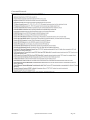
A wide variety of Converted POS protocols are supported (see partial list below). Which
protocol is appropriate for your application is determined by the device you are using –
which determines how the gateway communicates with the local device – and by the host
you are using – which determines how the gateway communicates with the host, converting
the data in both directions.
After selecting “SSL-Secured Protocols for Internet Connections”, select the appropriate
protocol from the list. Some protocols require additional information. If this is the case,
when you select that protocol an additional selection area will be visible under the “POS
Terminal to Network Host Conversion Settings” section.
80-001113
SysLINK Administrator’s Guide
Page 25
Converted Protocols
80-001113
SysLINK Administrator’s Guide
Page 26
Additional Converted Protocols
80-001113
SysLINK Administrator’s Guide
Page 27
SSL Options
When SSL is configured on an outgoing connection, you must also specify the SSL
connection parameters for each SSL peer. An SSL peer is the remote system that will be on
the other end of the secure SSL connection.
Type of Peer
For an outgoing connection the SSL Peer is normally an SSL Server. However, either side
can be a server or client. This option decides which is which during the SSL handshake.
Peer Identity Verification
This field can be used to enable verification of the remote peer's identity. Peer identity
verification must be enabled in order to guarantee that your secure data is not being
intercepted by an unwanted third-party. If you have specified the fully qualified domain
name (FQDN) in the peer address and this matches the SSL peer’s certificate, then click the
‘Certificate must match peer “”’ button. If you are using an IP address for the peer address,
check the ‘Certificate must belong to’ button and enter the FQDN. Or you may select ‘Don’t
verify peer’s identity’.
Caution: choosing ‘Don’t verify peer’s identity’ opens the possibility for an unwanted thirdparty to masquerade as a given peer on the Internet and intercept transactions. Normally
you should not choose this option.
SSL verifies peer identity by using signed certificates. To verify a remote peer's identity:
1) The remote peer must provide a valid certificate.
The remote peer must be configured to provide a valid certificate that proves its
identity.
2) The certificate must be signed by a trusted certification authority (CA).
80-001113
SysLINK Administrator’s Guide
Page 28
Certification authorities, or CAs, are organizations that issue and sign digital
certificates. To verify the integrity of a remote peer's certificate, its digital signature is
compared with the signatures of the CAs that are trusted by your application.
All trusted CAs must be pre-configured in the /usr/local/ssl/cert.pem file found in
the gateway’s local filesystem. This file contains certificates for trusted CAs and is
used to verify the integrity of remote peer certificates.
3) The certificate must be owned by the correct DNS domain.
For optimum security, signed certificates should contain a fully qualified domain
name (or FQDN) that ties the certificate to a particular host or domain. Otherwise,
anyone with a valid certificate from one of your trusted CAs could intercept your
secure transmission.
This field allows you to specify which domain name to expect in the certificate. If the
certificate does not contain the expected domain name, the connection will be
aborted.
Example
Supplying a peer FQDN of ssl.yourdomain.com will require that the remote peer provide a
certificate registered to ssl.yourdomain.com, and that the certificate is signed by one of the
certification authorities found in the gateway’s /usr/local/ssl/cert.pem file.
List of Allowable Ciphers
This field specifies which authentication and encryption protocols will be allowed for this
SSL connection. To maintain maximum security, it is important to allow only those ciphers
that are sufficiently secure.
The default cipher list allows only reasonably secure ciphers to be used. If the remote peer
does not support sufficiently modern ciphers, you may need to enable some of the lesssecure ciphers.
The cipher list is specified using the same format as the standard OpenSSL cipher lists. This
list is a set of cipher strings, separated by colons, that represents the available cipher suites:
ALL: All ciphers
HIGH: High-encryption ciphers (more than 128-bits)
MEDIUM: Medium-encryption ciphers (equal to 128-bits)
LOW: Low-encryption ciphers (56- and 64-bits, excluding export ciphers)
EXP: Export encryption ciphers
TLSv1: Transport Layer Security v1.0
SSLv3: Secure Sockets Layer v3.0
SSLv2: Secure Sockets Layer v2.0
DH: Diffie-Hellman Ciphers (including anonymous DH)
ADH: Anonymous Diffie-Hellman Ciphers
80-001113
SysLINK Administrator’s Guide
Page 29
kRSA: RSA Public Key Exchange
aRSA: RSA Authentication
3DES: Triple DES Encryption
DES: DES Encryption
RC4: RC4™ Encryption
RC2: RC2™ Encryption
MD5: MD5 128-bit Message Digest
SHA1: SHA1/DSS1 160-bit Message Digest
Each cipher may also be prefixed with one of the following operators:
-: Exclude cipher from list (may be re-added by later options)
+: Move cipher to the end of the list
!: Permanently exclude cipher from this list
Finally, the @STRENGTH cipher string may be appended to the end of the list to specify that
SSL negotiations give preference to higher-strength ciphers.
Click the help associated with this field to find the set of ciphers currently supported in the
software on your Gateway.
Example
The cipher string ALL:!SSLv2:!ADH:!LOW:!EXP:!MD5:@STRENGTH is commonly used to
disallow all the ciphers that are considered unacceptably weak. This cipher string enables all
the supported SSL ciphers except for: SSL version 2 handshaking, Anonymous DiffieHellman, low-encryption ciphers, export encryption ciphers, and MD5. In addition, the SSL
negotiation is instructed to choose the strongest ciphers supported by both SSL peers.
80-001113
SysLINK Administrator’s Guide
Page 30
Network Settings
The Network Settings page allows you to set a number of local IP options on the gateway.
IPv4 Address
You may permanently assign the IP address of the gateway by specifying it in this field.
Doing so will disable BOOTP/DHCP.
If you want to re-enable BOOTP/DHCP, you can do so by setting the IP address to 0.0.0.0, or
by restoring the default configuration (see the section called Restore Factory Defaults).
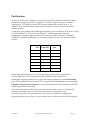
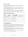
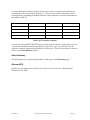
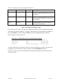
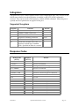
IPv4 Netmask
Every IP address contains two pieces of information: the network number and the host
number. A network number is assigned to each local area network and is shared by all the
network devices on that network. Each network device, or “host”, is assigned a unique host
number. The IP netmask defines which portion of an IP address contains the network
number, and which portion contains the host number. The default netmask depends on the
“class” of the IP address that you are using. These classes are defined in Table 2-1.
Class
IP Address
Default Netmask
Network Number
Host Number
A
0.0.0.0 to
127.255.255.255
255.0.0.0
n.0.0.0
0.h.h.h
B
128.0.0.0 to
191.255.255.255
255.255.0.0
n.n.0.0
0.0.h.h
C
192.0.0.0 to
223.255.255.255
255.255.255.0
n.n.n.0
0.0.0.h
Table 2-1: Default Netmasks
80-001113
SysLINK Administrator’s Guide
Page 31
It is often desirable to partition larger networks into a series of smaller networks that are
separated by routers (also called “gateways”). This process is called “subnetting” and is
accomplished by extending the default netmask. Some examples of common netmasks can
be found in Table 2-2.
IP Address
IP Netmask
Network Number
Host Number
192.168.10.1
255.255.255.0
192.168.10.0
0.0.0.1
10.11.12.13
255.0.0.0
10.0.0.0
0.11.12.13
10.11.12.129
255.255.255.0
10.11.12.0
0.0.0.129
10.11.12.129
255.255.255.248
10.11.12.128
0.0.0.1
Table 2-2: IP Netmask Examples
If you are not using DHCP/BOOTP and your network uses subnets (or supernets), you can
override the default net mask by specifying it in this field. Once you click the "Save IP
Address/Netmask" button these parameters will be saved. They will take effect on the next
reboot (see the Reset/Reboot section).
Default Gateway
The default gateway may be specified either on this page or the IP Routing page.
Ethernet MTU
Specifies the maximum size of packets sent on the local area network – the Maximum
Transmit Unit or MTU.
80-001113
SysLINK Administrator’s Guide
Page 32
TCP Keep-Alive
TCP keep-alive is a standard feature of TCP/IP that can be configured to automatically
monitor the state of TCP connections. If one end of an idle TCP connection is severed (like
by a network or power failure), it is possible for the other end to remain open indefinitely. If
a network host fails while it has an open TCP connection to one of the gateway’s serial ports,
that serial port might remain unavailable until it is manually reset.
The optional TCP keep-alive feature sends special “keep-alive” packets to the remote TCP
host in order to detect the situation where the remote host fails. If a failure is detected, the
TCP connection is reset to allow other hosts to access the serial port.
To enable TCP keep-alives on serial-related network connections, enter the total time (in
seconds) that you will allow TCP connections to remain idle before resetting them. The first
keep-alive packet will be sent after the connection has been idle for half of this total time.
After that, four more TCP keep-alive packets will be sent at regular intervals until a TCP
response is received from the remote host. If no response is received before the total keepalive time runs out, the TCP connection will be reset.
CAUTION: Enabling TCP keep-alives will increase the amount of network traffic on
your network. Unless you have a specific need for this feature, it is best to leave it
disabled. If you do enable it, it is best to make the keep-alive timeout larger to
reduce network traffic.
HTTP Server Configuration
You may specify the HTTP and HTTPS ports that the gateway will listen on for
configuration settings.
80-001113
SysLINK Administrator’s Guide
Page 33
Remote Management
Remote Management (RM) allows administrators to access a unit when it is behind a
firewall. When RM is enabled the gateway makes an outbound connection to an RM server
and waits for HTTP traffic. When a client (administrator) wants to access the gateway, they
point their browser at the RM server which connects the two.
You may manually specify a host and port and optionally select SSL, or you may click either
“Use Systech Secure Server” or “Use Systech Non-Secure Server” to select the default host
and SSL settings.
You may also configure RM but not enable it, then use the Light Weight Heart Beat
mechanism to enable RM only when it is needed.
80-001113
SysLINK Administrator’s Guide
Page 34
DNS Settings
The DNS Settings page allows you to specify a DNS name for your unit, specify the
addresses of DNS servers to resolve names, and to pre-define some host names. The DNS
name and servers can also be obtained from a DHCP server.
80-001113
SysLINK Administrator’s Guide
Page 35
If the gateway is configured to use DHCP, it will try to get DNS configuration information
from the DHCP server. You may also manually set up static DNS entries on this page.
Having DNS configured allows you to specify names in place of IP addresses in your
configuration.
The DNS Domain Name is used as the default domain for any names you specify. For
instance, if you specify the name “foo” in the ping command and the domain name
“company.com” in the DNS Domain Name above, the ping command will do a DNS lookup
on the name “foo.company.com”.
The DNS Server IP Addresses are used to specify the addresses of one or more machines that
can be used to resolve names to IP addresses.
The Static Hosts entries are used to define local host name to IP address mappings.
80-001113
SysLINK Administrator’s Guide
Page 36
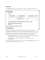
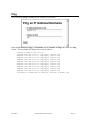
IP Routing
The IP Routing page lets you configure network routes for accessing remote networks:
If the gateway is configured to use DHCP, it will try to get gateway configuration
information from the DHCP server. You may also manually set up static routes on this page.
Each IP route consists of a destination IP address, a netmask, and a gateway IP address.
Depending on the netmask, the destination IP can specify one of two route types:
Network route: This is a route to an IP network. The netmask defines which portion
of the destination IP address contains the network number.
Host route: This is a route to a specific IP host. The netmask is always
255.255.255.255.
The special destination IP address of 0.0.0.0 or default specifies a default route, which is used
whenever a more specific route does not exist.
80-001113
SysLINK Administrator’s Guide
Page 37
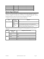
This is all summarized by the examples in Table 2-3.
Destination IP
Netmask
Gateway
Meaning
192.168.2.100
255.255.255.255
192.168.2.1
Host route: Send all packets destined for
IP address 192.168.2.100 to the router at
192.168.2.1
192.168.2.0
255.255.255.0
192.168.2.2
Network route: Send all packets destined
for the network 192.168.2.x to the router
at 192.168.2.2
0.0.0.0
ignored
192.168.2.3
Default route: Send all other packets to
the router at 192.168.2.3
Table 2-3: Examples of IP Route Types
For each route you wish to add, specify a destination address, select a destination netmask
and specify the gateway address. To specify a default route, set the destination address to
the word default or to the IP address 0.0.0.0, and select the Net destination netmask.
Some examples of valid routes are:
Destination AddressDestination NetmaskGateway Address
default
Net
192.168.2.1
10.10.10.0
Net
192.168.2.200
10.10.10.13
Host
192.168.2.201
10.0.0.0
Custom (255.255.255.0)
192.168.2.202
You must click the "Save Gateways" button to save any changes you make. The new route
configuration will take effect on the next reboot (see the Reset/Reboot section).
To remove a static route, clear the destination and gateway addresses then click the "Save
Gateway" button.
80-001113
SysLINK Administrator’s Guide
Page 38
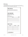
PPP Settings
The PPP Settings page lets you configure PPP on one or more ports. Typically this is used
for communication with some cellular modules. It may also be use for dial backup to a
dialup Internet Service Provider.
Basic settings:
Up to 5 PPP sets may be defined. Select the one you want to use. The specify the following:
Port to use for PPP connection
Phone number to dial
Username for PPP account
Password for PPP account
Inactivity timeout
Chat script
The PPP chat script entries consist of pairs of command/command arguments or expect
expressions/send text.
Two commands are supported: ABORT and TIMEOUT. The ABORT command argument is
a text string to be matched with the incoming chat text. When the chat processing sees a text
string matching an ABORT command argument, the current chat expression is aborted. The
TIMEOUT command argument is the number of seconds to use for the timeout.
80-001113
SysLINK Administrator’s Guide
Page 39
The expect expressions typically consist of text to be matched by the chat processing. When a
match is found, the corresponding send text is sent. Expect expressions can contain subexpressions separated by hyphens (-). Send text supports the following escape characters:
Escape
Substitution
\\L
username
\\P
password
\\T
phone number
\\c
suppress carriage return, linefeed
\r
carriage return
\n
linefeed
In some situations, the \\L and \\P escapes can be used in the expect expression to capture the
username and password.
80-001113
SysLINK Administrator’s Guide
Page 40
Time Settings
The Time Settings page allows you to configure NTP or HTTP time-servers to get the
system time from.
80-001113
SysLINK Administrator’s Guide
Page 41
If the gateway is configured to use DHCP, it will try to get NTP server information from the
DHCP server. You may also manually set up the addresses on this page.
If you are using SSL for peer verification or you are using the automatic update feature, the
gateway must obtain a valid time from an external time server.
The HTTP server you specify need not be a designated time server – just a reliable server.
The gateway derives the system time from the HTTP header the server returns.
The NTP service uses UDP port 123. If your gateway is behind a firewall you may need to
allow accesses to this port through the firewall.
80-001113
SysLINK Administrator’s Guide
Page 42
Security Settings
The security settings link includes settings for the System Passwords, Network Isolation and
access to the Security Log as defined in the following sections.
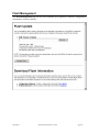
System Password
The gateway’s user interface and administrative functions can be protected with usernames
and passwords.
Two levels of authentication are supported – user and administrator. Users may view status.
Administrators may view status and logs and change settings.
Once a password is set, your web browser will prompt you for the authentication whenever
you try to access sensitive configuration pages. The browser will ask for a username and
password. The default username is “admin”. You may add other usernames and specify
both their password and authentication level. The admin username and password is also
used by Systech host utilities that manage the gateway.
A password must contain at least one numeric digit and one alpha character and be at least 7
characters in length. It may not contain any whitespace or control characters. A password
may not be longer than 15 characters. A password must be different than the previous four
passwords used for a given username.
Use the Reauthenticate button to request that the browser authenticate again.
80-001113
SysLINK Administrator’s Guide
Page 43
Network Isolation Configuration
By default, all network services are enabled. However, for security, any or all listening
services may be disabled. Unselect any services that you wish to disable. These changes
will not take effect until the next reboot.
80-001113
SysLINK Administrator’s Guide
Page 44
Security Log
The security log records security events. These include logins, changes to code,
configuration, or file system (FS). Both successful and failed events are logged along with
the timestamp of the event. The log is stored in non-volatile memory. You may view or
save the log but may not clear the log.
Click View to display the log (example below). Click Save to save the log to a file. You may
also configure the Online Update to periodically send the log to an update host.
80-001113
SysLINK Administrator’s Guide
Page 45
SSL Security Certificates
This page displays two sets of SSL certificates – the unit’s Identification Certificate and a list
of SSL peer and Certifying Authority certificates.
The SSL identification certificate identifies unit to remote SSL peers. During initialization,
the unit checks to see if an identification certificate exists. If not, it automatically generates
one and keeps it secure.
The public key portion of this certificate can be used by remote SSL servers to uniquely
identify the unit. This is sometimes known as client-side SSL authentication. To configure
client-side authentication on your server, perform one of the following steps:
Download the public key from the unit using the Download Public Key link and add
it to your SSL server's list of trusted SSL peers.
Use the Register/Install link to send the certificate to an HTTP server which supports
registration.
All SSL identity certificates have a private key which must be kept secret in order to
guarantee SSL security. The unit's firmware protects this private key by hiding it in internal
memory and never letting its contents leave the device. However, note that debug versions
of firmware remove these protections. In order to maintain the security of past and future
SSL transactions, the private key is destroyed whenever switching from secure production
firmware to debug firmware, and vice versa.
If the private key is destroyed by new firmware, the unit will automatically create a new
identity certificate after reboot. This new certificate must then be re-registered with your SSL
server(s).
80-001113
SysLINK Administrator’s Guide
Page 46
This list defines which SSL peers are trusted by this unit. When establishing an SSL
connection with an SSL peer, the unit checks this list to see if the peer's SSL certificate is
either: 1) in this list; or 2) signed by a certificate in this list. If so, the SSL peer is deemed to
be trusted and the SSL session is allowed to continue.
By default, this list is loaded with a number of popular Certifying Authorities (CAs) who sign
and issue SSL certificates to Internet hosts. To change the contents of this list, contact
customer support.
80-001113
SysLINK Administrator’s Guide
Page 47
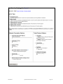
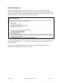
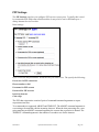
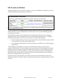
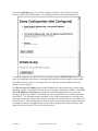
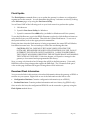
Online Update
You may configure your gateway to make a connection to an update server and obtain
updated software or configuration information from the server or send information to the
server. If your gateway supports SSL, this update may be over a secure SSL connection. You
may schedule the updates to happen periodically, or on every startup, or only when
manually selected. The automatic update capability can be used along with Network
Isolation to provide a way for the gateway to “call out” to get updates if all the incoming
connections are disabled.
To configure updates, first, select the update server to use and the SSL parameters for
connecting to it. You may specify both the server name and the path for obtaining the
updates. If the server requires HTTP authentication from the gateway, specify the username
and password to use.
80-001113
SysLINK Administrator’s Guide
Page 48
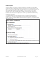
Then select when and what to update. Select “Perform update at startup” to have the
gateway check for updates every time it is booted. (Note: this will cause the startup to take
longer than normal. Do NOT interrupt the unit when it is updating or flash memory may be
corrupted. The unit will blink the status LED at four times the normal rate when it is
updating flash.) Or select a frequency and time of day to periodically check for updates.
80-001113
SysLINK Administrator’s Guide
Page 49
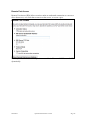
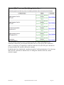
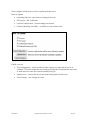
Then configure which items to send to the server or update from the server.
Send Information To Server:
Product Data – manufacturing configuration data, error records
Configuration Database – current settings on the unit (BDNL, text or URL-encoded
format)
System Log – trace activity
SSL Identity Certificate
Informational Fields
Alerts
o
Select the number of consecutive transaction failures to trigger a failure alert
o
Select the number of consecutive good transactions to trigger a subsequent
success alert (after a transaction failure alert)
Security Log – either the full log or only records changed since the last update.
80-001113
SysLINK Administrator’s Guide
Page 50
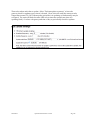
Then configure which items to send to update from the server.
Items to Update:
Operating Software – the software running in the unit
File System – SSL certificates
Current Configuration – current settings on the unit
Preferred Roaming List (PRL) – available on some cellular units
Finally, you can
Test Configuration – check to make sure the settings are right and the server is
available. This will contact the server and go through the communication necessary
to send and receive the files without actually doing so.
Update Now – contacts the server and sends and updates the files now.
Save Changes – save changes for later.
80-001113
SysLINK Administrator’s Guide
Page 51
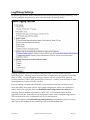
Lightweight Heartbeat Settings
The Lightweight Heartbeat (LWHB) feature is designed to provide a low overhead method
for units to check in more frequently than existing SOUP methods. This is particularly useful
when used with cellular data plans that provide only a few MB of data per month. Full
SOUP updates can be scheduled at most every day and have relatively high overhead (2030Kbytes per update). SOUP heartbeats can be scheduled more often but still relatively high
overhead (5-6K per heartbeat). The LWHB allows units to:
Check in frequently - providing an "I'm up" indicator
Check to see if there are further actions that should take place - like a full SOUP
update
The LWHB server can record the source IP address which, in the cellular world can change
multiple times a day
LWHB does not use SSL. It connects to a server using either UDP or TCP (configurable) on a
configurable port number. The local IP port can also be configured if necessary to receive
replies from the server through a firewall.
Using UDB, each LWHB takes about 60 bytes. Using TCP, each LWHB takes about 650 bytes.
You must also take into account periodic DNS lookups for the hostname.
80-001113
SysLINK Administrator’s Guide
Page 52
Specify the Hostname (or IP address), IP Destination Port and IP Protocol of the LWHB
server. Typically the IP Source Port should be 0, allowing the unit to use the next available
port.
The Lightweight Heartbeat client remembers the IP address of the server so that it does not
need to perform a DNS lookup for each heartbeat. The DNS Cache Period specifies how
long the server IP address is remembered before performing another DNS lookup. If a
heartbeat should fail to contact the server, then a DNS lookup is forced for the next attempt.
The Heartbeat Period defines how often to send a LWHB message.
A server response is optional, so the server may just hangup (TCP). For TCP, the client
detects the hangup and ends the heartbeat, but for UDP, the LWHB client wait for Response
Timeout seconds for any possible response.
If the server does respond, the response is a single string of comma-separated messages or
commands.
Response
Definition
"S"
Perform a full SOUP update action.
"C"
Perform a SOUP configuration database update action.
"P"
Perform a SOUP PRL update action.
"O"
Perform an Over-the-air (OTA) PRL update.
"R"
Reboot the unit.
"DR"
Disable Remote Management
"ER"
Enable Remote Management (must already be configured)
"Dn"
Disable Remote Port Access on port n
"En"
Enable Remote Port Access on port n (must already be configured)
Example: the following response string will cause the unit to do a SOUP update and enable
Remote Management:
C,R
80-001113
SysLINK Administrator’s Guide
Page 53
Cellular Settings
On units with Cellular modules, a Cellular Settings page is available to view the status of the
cellular module and, in some cases, change some settings. The following is an example of
the type of information available. This may vary depending on the module.
One some modules you may set the Service Programming Code (sometimes also called the
Master Subsidy Lock – MSL – or Alternative Lock). Under most circumstances this value is
not used. For some operations, like reconfiguration, it is used to reset values in the module.
80-001113
SysLINK Administrator’s Guide
Page 54
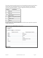
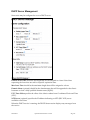
DHCP Server Management
Some units may be configured to act as a DHCP server.
Default Lease Time should be the length that will be assigned to a lease if the client
requesting the lease does not ask for a specific expiration time.
Max Lease Time should be the maximum length that will be assigned to a lease.
Domain Name (optional) should be the domain name that will be appended to the client's
hostname to form a fully-qualified domain-name (FQDN).
UTC Time Offset specifies the offset of the client's subnet from Coordinated Universal Time
(UTC).
NTP Server (optional) specifies the IP address indicating an NTP (RFC 1035) server
available to the client.
When the DHCP service is running, the DHCP Status section displays any messages from
the service.
80-001113
SysLINK Administrator’s Guide
Page 55
Accessing the Gateway from a Remote Network
When attaching TCP/IP devices to a local Ethernet network, all that is required for basic
communication is to assign an IP address to the network device. However, if your network
devices need to communicate with remote networks, you must also configure IP routing
information to tell TCP/IP where to send these remote network packets.
A remote network is a network that must be reached via one or more routers. To send
packets to a remote network, you must configure the following information:
1. IP Netmask: The IP netmask defines how your network is subnetted. See the section
called IPv4 Netmask for more information.
2. IP Routes: The IP routes define where your routers are and when to use them. See
the section called IP Routing for more information.
80-001113
SysLINK Administrator’s Guide
Page 56
Chapter 3: Troubleshooting and
Updating
There are a number of tools built into the gateway to facilitate troubleshooting problems and
managing the unit. These are accessible via the web browser interface under the menu
sections Status and Logs and Commands.
Troubleshooting displays high level information about transactions
System Log displays informational and error messages from the unit and can also be
configured to display debug trace data
OS Task Information displays the state of the onboard software tasks
Error! Reference source not found. displays the status of network services and current
connections
Error! Reference source not found. displays the status of the currently active network
interfaces
Port Status displays the current state of the port(s)
Log/Debug Settings configures the type of trace data to collect in the System Log
Ping can be used to test network connections
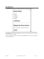
Reset/Reboot can be used to clear errors on individual ports or to reboot the gateway
Flash Management allows you to update the unit’s software, save and update
configuration information, and manage the error history of your gateway
80-001113
SysLINK Administrator’s Guide
Page 57
Troubleshooting
The troubleshooting section displays high level information about transactions. Example:
80-001113
SysLINK Administrator’s Guide
Page 58
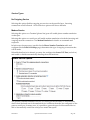
System Log
By default, the gateway stores informational and error messages in the system log. You can
also configure the gateway to record debug trace data in this system log buffer (see the
section entitled Log/Debug Settings). To display the system log and trace information in
your browser window, select the System Log link in the menu:
This will open a connection to the gateway that will display the current contents of the
system log buffer. As long as you keep this window open in your browser, new messages
added to the buffer will automatically be sent to your web browser.
Log entries begin with a timestamp. The first item “(0)” is the number of days since the unit
was booted. The next 12 digits are the time in UTC time including microseconds.
Click the “save” link next to System Log to save the log as an HTML file. Click the “clear”
link next to System Log to clear the log.
You can also view and save the system log using a telnet client. To do this, connect to the IP
address of your gateway on TCP port 9096. Data in the trace buffer will be automatically
formatted and displayed in your telnet window. For example:
telnet 192.168.1.1 9096
80-001113
SysLINK Administrator’s Guide
Page 59
You can also use the r4000 host utility –s or –t options. –s gets the current contents of the
trace log then quits and –t gets the log continuously.
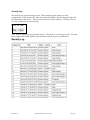
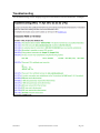
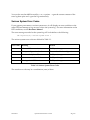
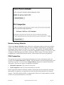
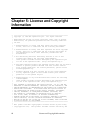
Serious System Error Codes
If your gateway encounters a serious system error, it will display an error condition on the
status LED and attempt to log an error code to the system log. For more information on the
LED conditions, see the Hardware Manual.
The error message recorded to the system log will look similar to the following:
382 log-error[10]: Serious system error 1
The serious system error codes are defined in Table 3-1.
Error Code
Meaning
Action
1
Ethernet MII communication error
Call Systech support
2
Corrupt configuration database.
Restore the default configuration
4
Unknown backplane ID
Call Systech support
8
Unknown network module
Call Systech support
16
Missing or bad DSP device
Call Systech support
Table 3-1: Serious System Error Codes
The actual error code may be a combination (sum) of these.
80-001113
SysLINK Administrator’s Guide
Page 60
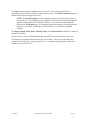
Port Status
The Port Status page shows the current state of the port(s):
The DCD, RTS, CTS, DTR, DSR, and RI columns indicate the status of the modem signals
for the specified port. If the modem signal is present (either asserted if it is an outgoing
signal, or detected if it is an incoming signal) its name will appear in the corresponding
column.
80-001113
SysLINK Administrator’s Guide
Page 61
The State column indicates whether the port is open, closed, waiting for DCD, or
experiencing any notable conditions (such as flow control). The Serial Parameters column
indicates the current settings for the port.
NOTE: The Serial Parameters column reflect the actual, real-time serial settings in
use by the port. The settings that are specified via the serial configuration pages are
applied each time the port is opened. If the port is closed, the serial parameters
reported by Port Status may not necessarily match the settings you configured until
the port is re-opened. Furthermore, some clients can override the configured
settings.
The Input, Output, Parity Errors, Framing Errors, and Overrun Errors columns are tallies of
activity on the port.
Under each port row is a field indicating the current TCP connection status on the port.
The display will update automatically every few seconds. You can stop the automatic
update by selecting "Stop" from your browser. To restart the updating, select "Refresh" or
"Reload" from your browser.
80-001113
SysLINK Administrator’s Guide
Page 62
OS and Network Information
The OS and Network Information page shows the current state of system and application
tasks as well as memory usage information and displays the status of network services and
current connections. This may include:
OS Information
CPU Information
Memory Information
Filesystem Information
Network Information
TCP Sockets – established connections and listeners
UDP Listeners – UDP ports the unit is listening on
Network Interfaces
Current Route Table
Network Interface Statistics
Temperature Monitor Settings
On units with temperature monitoring hardware, the following page is present.
The sampling period determines how often the temperature monitor takes a temperature
reading. This period, combined with the counts, determines the amount of time and
80-001113
SysLINK Administrator’s Guide
Page 63
hysterisis in triggering over and under temperature events and return to normal
temperature events.
An event is currently defined as an Alert which is sent to the SOUP server.
Motion Detection Settings
On units with motion monitoring hardware, the following page is present.
The detection sensitivity determines how much motion is needed to generate a motion
event. The motion detection sensitivity can be chosen from a predefined list of values.
Choices are Disabled, Low, Medium, and High.
A motion event action occurs when the number of motion events (or more) occurs during
the detection period. After a motion event action occurs, any additional motion events will
be ignored for the reset time period.
An event is currently defined as an Alert which is sent to the SOUP server.
80-001113
SysLINK Administrator’s Guide
Page 64
Log/Debug Settings
By default, the gateway stores informational and warning messages in the system log. You
can also configure the gateway to save trace data in this system log buffer:
Tracing is generally used for troubleshooting problems. You can enable tracing on
individual ports – selecting low-level serial events or higher-level port service events (like
telnet or LPD). Or you can enable tracing on system services such as HTTP (the web
browser interface), DHCP, SDP (Systech Device Protocol - used by Systech utilities to find
Systech gateways on the network), and SSL.
For port tracing, you must select both the port(s) and the events that you want to trace.
Note that unlike most other options, the logging configuration will not be saved after a
reboot unless you explicitly check the Remember this configuration after reboot box.
Selecting “Record modem negotiations to WAV files” will record the latest modem
negotiation from the Terminal ports (from the time it dials until it completes negotiation).
This can then be saved to a standard WAV file for later analysis.
Refer to the chapter on Troubleshooting and Updating for information on how to access
and capture the contents of the system log or the recorded modem data.
80-001113
SysLINK Administrator’s Guide
Page 65
From the Log/Debug page you can also configure the unit to save a dump of system
memory under some circumstances. Scroll the page down to the dump information:
A memory dump may be obtained either manually using the Initiate Dump button on this
page or pressing the reset button or automatically when the unit encounters a catastrophic
error that causes it to reboot. No dump will occur with any of these methods unless the
dump is first configured.
The Device Server IP Address specifies the IP address the unit should use as its own when
initiating a dump. If left blank, the unit uses it’s currently configured IP address. The TFTP
Server IP Address and Filename specify the host and filename on that host to send the
dump to. If the server address is left blank, the unit uses the TFTP server address obtained
from DHCP. The filename must be specified. If any of these parameters are invalid at the
time of the dump, the dump will be aborted. The filename must be that of a writeable file on
the TFTP server. The two IP addresses must be on the same segment (the dump facility does
not support routing). The r4000 utility can be used to configure and initiate a dump. This
utility can also act as the TFTP server for this purpose.
80-001113
SysLINK Administrator’s Guide
Page 66
Ping
You can use the Ping command to test a network connection:
Enter the IP address to Ping or a Hostname and the Number of Pings then press the Ping
button. The command will display the results as follows:
Sending 10 PINGs to 209.75.217.6...
Response from 209.75.217.6: icmp_seq=0, time=10.0 ms
Response from 209.75.217.6: icmp_seq=1, time=10.0 ms
Response from 209.75.217.6: icmp_seq=2, time=10.0 ms
Response from 209.75.217.6: icmp_seq=3, time=10.0 ms
Response from 209.75.217.6: icmp_seq=4, time=10.0 ms
Response from 209.75.217.6: icmp_seq=5, time=10.0 ms
Response from 209.75.217.6: icmp_seq=6, time=10.0 ms
Response from 209.75.217.6: icmp_seq=7, time=10.0 ms
Response from 209.75.217.6: icmp_seq=8, time=10.0 ms
Response from 209.75.217.6: icmp_seq=9, time=10.0 ms
10 packet(s) transmitted, 10 packet(s) received, 0% packet loss.
80-001113
SysLINK Administrator’s Guide
Page 67
Reset/Reboot
The Reset/Reboot page lets you reset individual ports, or the entire gateway:
You can reset an individual port or ports by selecting the desired port(s) and pressing the
Reset Port(s) button. This will kill whatever service was on the port and reset it back to the
current configuration settings.
You may reboot the entire gateway by pressing the Reboot button. This is the equivalent of
power cycling the unit.
80-001113
SysLINK Administrator’s Guide
Page 68
Flash Management
The Flash Management page allows you to maintain your gateway’s software, configuration
information, and error history:
80-001113
SysLINK Administrator’s Guide
Page 69
Flash Update
The Flash Update command allows you to update the gateway’s software or configuration
segment across the network. You can determine the gateway’s software revision by looking
at the Welcome page, or by using the Port Server Utility.
You will need ONE of the following tools on your local network to perform the update:
1. Web browser
2. Systech’s Port Server Utility for Windows
3. Systech’s command-line r4000 utility (available for Windows and Unix systems)
To use the Web Browser, type in the BDNL filename to upload or click the Browse button to
select the file from your local machine. Then click the Update Flash button. To use one of
the Systech utilities, refer to the appropriate documentation.
During the time when the flash memory is being programmed, the status LED will blink at
four times its normal rate. Do not interrupt or reboot the unit during this time.
CAUTION: SPECIAL CARE MUST BE TAKING WHEN UPDATING THE
SOFTWARE. REGARDLESS OF WHICH UPDATE METHOD YOU USE, DO NOT
INTERRUPT THE UPDATE ONCE IT HAS BEGUN. LOSING POWER DURING
THE UPDATE WILL RISK CORRUPTING THE SOFTWARE IMAGE AND MAKING
THE GATEWAY UNUSABLE. If this does happen, call Systech to arrange for the
gateway to be returned and reprogrammed at the factory.
Note: you may only download an OS image that will fit in the flash memory. Units with
1MB flash will not accept images that require the 2MB flash. The “Firmware flash space”
value on this page indicates the largest OS image that will fit in this unit.
Download Flash Information
You can use the links in this section to download information about the gateway to BDNL or
text files on your system. Right-click on one of the links and save the link to a file:
Configuration Database: Contains configuration information (text or BDNL)
Product Data Area: Contains product information and error history log (BDNL-only)
Once saved to the host, the configuration BDNL file can be restored to a gateway using the
Flash Update method above.
80-001113
SysLINK Administrator’s Guide
Page 70
Restore Factory Defaults
Clicking the Restore Defaults button will set the configuration back to the factory default
values. You can also restore the gateway’s factory default configuration by pressing and
holding the "Reset" button for a little over 5 seconds. The gateway will initially blink the
status LED red and yellow to notify you that the configuration is about to be restored. After
it changes to blinking green and yellow, release the “Reset” button. The factory default
configuration is restored and the unit reboots. Either method will reboot the gateway.
PDA Compaction
The gateway stores factory configuration information, boot time information, and error
records in the Product Data Area (or PDA). This information is stored in flash memory and
can fill up over time. You can use the Compact Flash command to reclaim Product Data
Area space. There are two types of compaction operations:
Standard Compaction: only removes old records
Total Compaction: removes old records and error records
Each Compaction method will list the number of bytes that can be reclaimed by selecting
that method. In general, you should never need to do this unless directed to by Systech
support. The flash used by the PDA is independent of the rest of system memory, and has
no effect on system performance or resources.
80-001113
SysLINK Administrator’s Guide
Page 71
If you select Total Compaction, you should save the PDA to a host file before compacting.
The error records may be useful to Systech support personnel for debugging hardware and
software problems on your gateway. Select the type of compaction you would like and
press the Compact Flash button.
Other Debugging
Refer to the hardware manual for a description of the LED activity during operation of the
gateway.
If you are using RTN on the host system, you can also use the debugging tools in that
product with the gateway.
80-001113
SysLINK Administrator’s Guide
Page 72
Chapter 4: Modem Emulation
The gateway can be configured to allow legacy devices that interact with a Hayes
compatible modem to function over a TCP/IP network. When modem emulation is enabled
on a serial port, the gateway will respond to AT commands generated by the attached
device. After receiving the dial command, the gateway will make a TCP connection to the
specified host. The gateway will also accept incoming TCP/IP connections and generate the
appropriate response codes. As with incoming TCP connections, each Systech serial port
accepts incoming TCP connections on two TCP ports: an 8000-series port (for raw or SSL
data), and a 9000-series port (for telnet data).
Modes
A port with modem emulation enabled can be in one of two modes: command or data. The
port starts out in command mode. In command mode, the port is only interacting with the
host/device connected to the serial port. It accepts AT style command interaction and
responds appropriately. Successfully making an outgoing connection, ("dialing" with the
ATD command) or accepting an incoming connection ("answering" with the ATA command)
switches the port to data mode. In data mode, characters received on the serial port are
transmitted to the TCP connection and vice versa.
Escape Sequence
When in data mode, the gateway looks for an incoming escape sequence on the serial port.
The escape sequence consists of a pause, three break characters ('+'), and a final pause. Upon
receiving this sequence, the port switches to command mode. The default pause is one
second but can be changed in the S12 register. The escape character ("+")is not
programmable.
Types of TCP/IP connections
TCP/IP connections may be in raw TCP mode (with or without SSL security), telnet or telnet
binary mode. These are the same settings available for the Incoming/Outgoing network
connection services on the gateway. In raw mode, TCP data is passed to/from the TCP/IP
connection without any modification. In telnet and telnet binary mode, data coming in the
TCP/IP connection is scanned for telnet sequences that are handled appropriately. In telnet
binary mode, outgoing TCP/IP connections attempt to negotiate telnet binary mode. Telnet
and telnet binary connections may negotiate RFC 2217 mode.
80-001113
SysLINK Administrator’s Guide
Page 73
Outgoing and Incoming Calls
After automatically accepting an incoming connection, the gateway will begin generating
"RING" response codes to the device at 6-second intervals. Incoming network data is
buffered until the device completes the connection by entering data mode. The device may
enter data mode either manually by issuing the "ATA" command, or automatically after
receiving the number of rings specified in register S0. If the gateway is configured such that
DCD will follow the connection status (AT&C1), DCD will remain low until the connection
is completed. If not (AT&C0), DCD will remain asserted at all times.
Outgoing calls are made by the ATD command. This initiates an attempt to make a
connection to the specified IP:port pair (see Phone Numbers below). A successful
connection will send the "CONNECT" result code out the serial port and enter data mode.
However, if the dialstring was suffixed with a ';', the modem will return to command mode
after establishing a connection. If the connection fails for any reason, the "NO CARRIER"
result code is returned.
AT Commands
All AT command strings, with the exception of the break sequence ("+++") and the repeat
command ("A/"), must be terminated with the command line termination character, defined
in S3 (default is CR). All characters before 'AT' are ignored. Unsupported commands are
ignored and generate an "OK" result code. Multiple commands may be combined on a
single line, however the AT command string is currently limited to 40 characters.
Example:
AT&FE0V0
80-001113
SysLINK Administrator’s Guide
Page 74
Supported Commands
Command
Function
/
Repeat last command
Result
Varies
Note: command executes upon "/"
character. CR not needed.
OK(0)
<blank>
Attention
A
Answer
Dial
OK(0), NO CARRIER(3)
CONNECT(1), NO CARRIER(3)
If suffixed with ";" character, will return to
command mode upon connection.
Echo Mode
0=Turn command echo off
1=Turn command echo on (default)
Hangup
Terminate connection.
Optional argument has no function
Information
0=Serial Port Speed
3= Model and Version
Return to data mode from command
mode
Result Codes
0=Enable result codes (default)
1=Supress result codes
Set register to specified value (see
below)
Return current value formatted as 3
digit decimal
Result Code Format
0=Numerical result codes
1=Verbose result codes (default)
OK(0)
D
En
Hn
In
O
Qn
Sn=mm
Sn?
Vn
Xn
Zn
80-001113
Result Code Format
0="CONNECT" upon entering
online data state
1-4="CONNECT <text>" upon
entering online data state
Load factory default settings and
drop current connection. This
command also restores the flash
configuration for the port back to
factory default.
OK(0)
33600 (Note: Actual value equals current
port speed)
OK(0)
<blank>
OK(0)
0
OK
OK(0)
OK(0)
SysLINK Administrator’s Guide
Page 75
&Cn
&Dn
&F
&Fn
&V
&V0
&V1
DCD Control
0=DCD always on
1=DCD follows connection status
(default)
DTR Control
0=ignore
1=loss of DTR switches to command
mode and leaves connection open
2=loss of DTR switches to command
mode and closes connection
(default)
Load factory default settings
Equivalent to ATZ without dropping
the connection. This command does
not affect the flash configuration for
the port.
Display S-register values
OK(0)
Status
Returns reason for the last disconnect:
OK(0)
OK(0)
Ex:
E0 Q1 V0 &C1 &D2
S00:002 S02:043 S03:013 S04:010 S05:008
TERMINATION REASON......DTR LOSS
TERMINATION REASON….CARRIER LOSS
&W
&Wn
&Xnnn
Write current configuration to flash
OK(0)
Change baud rate.
Nnn Baud
3
300
12
1,200
24
2,400
48
4,800
96
9,600
14
14,400
19
19,200
28
28,800
38
38,400
57
57,600
115
115,200
OK(0)
&x
%x
Any other & command is ignored
Any % command is ignored
OK(0)
OK(0)
+x
$xn
Any + command is ignored
Any $ command is ignored
including 0 or more digits after the
command.
OK(0)
OK(0)
80-001113
SysLINK Administrator’s Guide
Page 76
S-Registers
S Registers are 1 byte, volatile registers used to store configuration data. They are reset to the
default state whenever modem emulation is enabled, or the ATZ/AT&F command is
received. They can be saved to flash memory with the AT&W command. When the port is
opened, the saved parameters are applied to the port.
Supported S-registers
Register
S0
S1
Contents
Automatic Answer(# of RING's)
Number of RING's Received
Default
0(disabled)
0
S3
S4
S5
S12
Command Line Termination Character CR(13)
Response Formatting Character
LF(10)
Command Line Editing Character
BS(08)
Guard time on either side of the +++ 50
sequence to break into command
mode. Specified in 50ths of a second.
Response Codes
Result Code
(ATV1)
Numeric
(ATV0)
Reason
OK
CONNECT
RING
0
1
2
Command Successful
NO CARRIER
ERROR
CONNECT 1200
3
4
5
Connection Terminated
NO DIALTONE
BUSY
6
7
Not Used
NO ANSWER
CONNECT 2400
8
10
Not Used
CONNECT 4800
11
Connected – Serial Port Speed is 4800 baud
CONNECT 9600
CONNECT 14400
CONNECT 19200
CONNECT 28800
12
13
14
15
Connected – Serial Port Speed is 9600 baud
80-001113
Connection Established
Incoming connection awaiting answer
Error in AT command string
Connected – Serial Port Speed is 1200 baud
Not Used
Connected – Serial Port Speed is 2400 baud
Connected – Serial Port Speed is 14400 baud
Connected – Serial Port Speed is 19200 baud
Connected – Serial Port Speed is 28800
SysLINK Administrator’s Guide
Page 77
CONNECT 38400
28
Connected – Serial Port Speed is 38400 baud
CONNECT 57600
18
Connected – Serial Port Speed is 57600 baud
CONNECT 115200
CONNECT 230400
31
65
Connected – Serial Port Speed is 115200 baud
Connected – Serial Port Speed is 230400 baud
Modem Signal Behavior
The gateway serial ports should be set to DCE mode when modem emulation is enabled. A
DCE port is designed to be connected to a DTE device via a straight-through cable. Refer to
the gateway hardware manual for specific pinout information for your unit.
To emulate a modem properly, the gateway does the following:
Mode
Command/Data
Modem DCD
Settings
Always on
(&C0)
Follow
connection
(&C1)
Behavior
DCD is asserted
DCD is asserted only when TCP/IP connection is
present and has been accepted via ATA or auto-answer.
DCD is de-asserted when connection is lost
The gateway monitors the device's DTR signal. The following behaviors occur on loss of
DTR only.
Mode
Offline
Online
80-001113
Modem DTR
Settings
AT&D0
AT&D1
AT&D2
AT&D0
Response to loss of DTR
Ignore
Ignore
Ignore
Ignore
AT&D1
AT&D2
Drop to command mode, preserving connection
Drop to command mode, terminating any connection
SysLINK Administrator’s Guide
Page 78
Phone Numbers
The "phone number" used in an outgoing connection for an "ATD" command may be a real
phone number that is translated to an IP/port pair (see Phone Number Translation) or it
consists of an IP address and port number. All leading non-numeric characters (such as the
T or P dial modifiers) are ignored. A number of formats are accepted for the “IP” phone
number.
Format
Dotted decimal
Example
a.b.c.d
192.168.1.1
Notes
Numbers are from 0 to 255
Comma decimal
a,b,c,d
192,168,1,1
For programs that don't allow dots in phone numbers
Fixed format
aaabbbcccddd
192168001001
:xxxxx
12 digit IP address, each number is three decimal digits
with leading zeroes
Decimal TCP port number from 0..65535
Port number
The source port for the TCP connection follows the Source TCP Port configured for
the port.
Port Settings
Serial ports used for modem emulation should be set to DCE mode. Most of the other serial
port settings (like baud rate) are controlled by the configured port settings on the gateway.
Modem emulation does not support changing these from AT commands.
80-001113
SysLINK Administrator’s Guide
Page 79
Chapter 5: License and Copyright
Information
/*
*
*
*
*
*
*
*
*
*
*
*
*
*
*
*
*
*
*
*
*
*
*
*
*
*
*
*
*
*
*
*
*
*
*
*
*
*
*
*
*
*
*
*
*
*
*
*
*
*
80
====================================================================
Copyright (c) 1998 The OpenSSL Project. All rights reserved.
Redistribution and use in source and binary forms, with or without
modification, are permitted provided that the following conditions
are met:
1. Redistributions of source code must retain the above copyright
notice, this list of conditions and the following disclaimer.
2. Redistributions in binary form must reproduce the above copyright
notice, this list of conditions and the following disclaimer in
the documentation and/or other materials provided with the
distribution.
3. All advertising materials mentioning features or use of this
software must display the following acknowledgment:
"This product includes software developed by the OpenSSL Project
for use in the OpenSSL Toolkit. (http://www.OpenSSL.org/)"
4. The names "OpenSSL Toolkit" and "OpenSSL Project" must not be used to
endorse or promote products derived from this software without
prior written permission. For written permission, please contact
[email protected].
5. Products derived from this software may not be called "OpenSSL"
nor may "OpenSSL" appear in their names without prior written
permission of the OpenSSL Project.
6. Redistributions of any form whatsoever must retain the following
acknowledgment:
"This product includes software developed by the OpenSSL Project
for use in the OpenSSL Toolkit (http://www.OpenSSL.org/)"
THIS SOFTWARE IS PROVIDED BY THE OpenSSL PROJECT ``AS IS'' AND ANY
EXPRESSED OR IMPLIED WARRANTIES, INCLUDING, BUT NOT LIMITED TO, THE
IMPLIED WARRANTIES OF MERCHANTABILITY AND FITNESS FOR A PARTICULAR
PURPOSE ARE DISCLAIMED. IN NO EVENT SHALL THE OpenSSL PROJECT OR
ITS CONTRIBUTORS BE LIABLE FOR ANY DIRECT, INDIRECT, INCIDENTAL,
SPECIAL, EXEMPLARY, OR CONSEQUENTIAL DAMAGES (INCLUDING, BUT
NOT LIMITED TO, PROCUREMENT OF SUBSTITUTE GOODS OR SERVICES;
LOSS OF USE, DATA, OR PROFITS; OR BUSINESS INTERRUPTION)
HOWEVER CAUSED AND ON ANY THEORY OF LIABILITY, WHETHER IN CONTRACT,
STRICT LIABILITY, OR TORT (INCLUDING NEGLIGENCE OR OTHERWISE)
ARISING IN ANY WAY OUT OF THE USE OF THIS SOFTWARE, EVEN IF ADVISED
OF THE POSSIBILITY OF SUCH DAMAGE.
====================================================================
This product includes cryptographic software written by Eric Young
([email protected]). This product includes software written by Tim
License and Copyright Information
* Hudson ([email protected]).
*
*/
__________________________________________________________________________
Original SSLeay License
__________________________________________________________________________
Copyright (C) 1997 Eric Young ([email protected])
All rights reserved.
This package is an SSL implementation written by Eric Young ([email protected]).
The implementation was written so as to conform with Netscapes SSL.
This library is free for commercial and non-commercial use as long as
the following conditions are aheared to. The following conditions
apply to all code found in this distribution, be it the RC4, RSA,
lhash, DES, etc., code; not just the SSL code. The SSL documentation
included with this distribution is covered by the same copyright terms
except that the holder is Tim Hudson ([email protected]).
Please note that MD2, MD5 and IDEA are publically available standards
that contain sample implementations, I have re-coded them in my own
way but there is nothing special about those implementations. The DES
library is another mater :-).
Copyright remains Eric Young's, and as such any Copyright notices in
the code are not to be removed.
If this package is used in a product, Eric Young should be given attribution
as the author of the parts of the library used.
This can be in the form of a textual message at program startup or
in documentation (online or textual) provided with the package.
Redistribution and use in source and binary forms, with or without
modification, are permitted provided that the following conditions
are met:
1. Redistributions of source code must retain the copyright
notice, this list of conditions and the following disclaimer.
2. Redistributions in binary form must reproduce the above copyright
notice, this list of conditions and the following disclaimer in the
documentation and/or other materials provided with the distribution.
3. All advertising materials mentioning features or use of this software
must display the following acknowledgement:
"This product includes cryptographic software written by
Eric Young ([email protected])"
The word 'cryptographic' can be left out if the rouines from the library
being used are not cryptographic related :-).
4. If you include any Windows specific code (or a derivative thereof) from
the apps directory (application code) you must include an acknowledgement:
"This product includes software written by Tim Hudson ([email protected])"
THIS SOFTWARE IS PROVIDED BY ERIC YOUNG ``AS IS'' AND
ANY EXPRESS OR IMPLIED WARRANTIES, INCLUDING, BUT NOT LIMITED TO, THE
IMPLIED WARRANTIES OF MERCHANTABILITY AND FITNESS FOR A PARTICULAR PURPOSE
ARE DISCLAIMED. IN NO EVENT SHALL THE AUTHOR OR CONTRIBUTORS BE LIABLE
FOR ANY DIRECT, INDIRECT, INCIDENTAL, SPECIAL, EXEMPLARY, OR CONSEQUENTIAL
DAMAGES (INCLUDING, BUT NOT LIMITED TO, PROCUREMENT OF SUBSTITUTE GOODS
OR SERVICES; LOSS OF USE, DATA, OR PROFITS; OR BUSINESS INTERRUPTION)
HOWEVER CAUSED AND ON ANY THEORY OF LIABILITY, WHETHER IN CONTRACT, STRICT
LIABILITY, OR TORT (INCLUDING NEGLIGENCE OR OTHERWISE) ARISING IN ANY WAY
OUT OF THE USE OF THIS SOFTWARE, EVEN IF ADVISED OF THE POSSIBILITY OF
SUCH DAMAGE.
The licence and distribution terms for any publically available version or
derivative of this code cannot be changed. i.e. this code cannot simply be
copied and put under another distribution licence
[including the GNU Public Licence.]
License and Copyright Information
81
The reason behind this being stated in this direct manner is past
experience in code simply being copied and the attribution removed
from it and then being distributed as part of other packages. This
implementation was a non-trivial and unpaid effort.
82
License and Copyright Information
Index
A
AT commands, 75
B
baud, 12
bits per character, 12
BOOTP, 7
browser, 11
C
character size, 12
class, IP, 33
compaction, 73
configuration, 7
D
DCD, 18
DCE/DTE, 13
debugging, 74
default configuration, 73
default gateway, 39
default route, 39
destination IP address, 18
destination TCP port, 18
DHCP, 7
DNS, 37
domain name, 38
DTR/DSR, 12
dump memory, 68
E
End-of-Dial Timeout, 13
error code, 62
Errors
Framing, 64
Overrun, 64
Parity, 64
escape character, 19
F
factory default, 73
FastConnect, 13
Flash Management, 71
Flash Update, 72
flow control, 12
DTR/DSR, 12
RTS/CTS, 12
XON/XOFF, 12
FQDN, 30, 31
G
gateway, 39, 41
H
host route, 39
I
incoming connection, 10, 14, 76
IP
address, 33
class, 33
destination address, 18
netmask, 33, 34, 58
route, 39, 41, 58
K
keep-alive, 35
keyboard hit, 19
L
log, 61
Log/Debug, 67
Index
83
M
memory dump, 68
modem
response codes, 79
modem emulation, 9, 16, 75
modem signals, 63, 80
N
name server, 37
netmask, 33, 34, 58
network route, 39
network settings, 33
NTP, 43
O
outgoing connection, 8, 9, 14, 16, 18, 76
P
parity, 12
password, 45
phone number, 81
phone number translation, 21
Ping, 69
Port Server Utility, 72
port services, 14
port status, 63
Product Data Area, 72
Q
quiet mode, 19
R
r4000 utility, 72
reboot, 70
remote network, 39, 58
Require carrier, 18
require DCD, 18
reset ports, 70
response codes, 79
restart delay, 18
restore default configuration, 73
84
RFC-2217, 12
routes, 58
RTS/CTS, 12
S
S Registers, 79
serious system error, 62
SSL mode, 30
status, port, 63
stop bits, 12
system log, 61
system password, 45
T
task, 65
TCP
destination port, 18
keep-alive, 35
port 8000-9000, 10, 75
port 9096, 62
telnet, 19
telnet binary mode, 19
telnet escape character, 19
telnet mode, 19
Telnet Mode, 19
terminal type, 19
time server, 43
troubleshooting, 59, 67
U
update software, 59, 72
utility
Port Server, 72
r4000, 62, 72
W
wait for keyboard hit, 19
web browser, 7, 11, 72
X
XON/XOFF, 12
Index