1
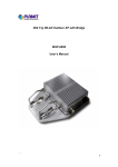
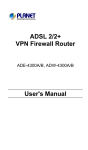
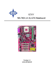
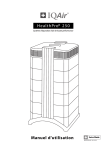
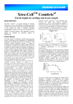
DCTS-900
Wireless Handset
USER’S MANUAL
MobiCel Systems, Inc. has made every effort to
ensure the technical accuracy of this manual.
Features and technical data are subject to
change without notice.
Copyrightã 1997, MobiCel Systems, Inc. All
Rights Reserved.
WARNING
MobiCel Systems, Inc. doesn’t represent this
unit to be waterproof. To reduce the risk of
fire, electrical shock, or damage to the unit, do
not expose this unit to rain or moisture.
NICKEL METAL
HYDRIDE BATTERY
WARNING
One Nickel Metal Hydride battery is provided
with each handset. This battery may not be
fully charged when received. Charge the
battery before using the wireless handset. Refer
to “Charging the Handset Battery” in the
Installation section of this manual. The
charging time is approximately one (1) hour.
TO PREVENT FIRE OR SHOCK
HAZARD, DO NOT EXPOSE THE UNIT
TO RAIN OR MOISTURE.
IMPORTANT SAFETY
INSTRUCTIONS
When using your telephone equipment, basic
safety precautions should always be followed to
reduce the risk of fire, electrical shock, and
injury to persons, including the following:
1. Read and understand all instructions.
2. Follow all warnings and instructions
marked on the product.
3. Unplug this product from the wall outlet
before cleaning. Do not use liquid cleaners
or aerosol cleaners. Use a dry cloth for
cleaning.
4. Do not use this product near water; for
example, near a sink or in a wet area.
5. Do not place this product on an unstable
cart, stand, or table. The telephone may
fall, causing serious damage to the unit.
6. To protect the product from overheating,
do not block or cover any slots or openings
i
in the cell unit. This product should never
be placed near or over a radiator or heat
register. This product should not be placed
in a built-in installation unless proper
ventilation is provided.
7. This product should be operated only from
the type of power source indicated on the
marking label.
8. Do not allow anything to rest on the power
cord. Do not locate this product where the
cord will be damaged by persons walking
on it.
9. Do not overload wall outlets and extension
cords, as this can result in the risk of fire
or electrical shock.
10. Never push objects of any kind into this
product through the cell unit slots, as they
may touch dangerous voltage points or
short out parts that could result in a risk of
fire or electric shock.
11. To reduce the risk of electric shock, do not
disassemble this product. Contact
qualified service personnel when some
service or repair work is required.
Opening or removing covers may expose
you to dangerous voltages or other risks.
Incorrect reassembly can cause electric
shock when the product is subsequently
used.
12. Unplug this product from the wall outlet
and refer servicing to qualified service
personnel under the following conditions:
a. When the power supply cord is
damaged or frayed.
b. If liquid has been spilled into the
product.
c. If the product has been exposed
to rain or water.
d. If the product does not operate
normally when following the
operating instructions. Adjust
only those controls that are
covered by the operating
instructions. Improper
adjustment of other controls may
ii
result in damage and will often
require extensive work by a
qualified technician to restore the
product to normal operation.
e. If the product has been dropped
or the cabinet has been damaged.
f. If the product exhibits a distinct
change in performance.
13. Do not use the telephone to report a gas
leak in the vicinity of the leak.
CAUTION
To reduce the risk of fire or injury to persons by
the battery, read and follow these instructions:
1.
2.
3.
4.
5.
6.
Use only the appropriate type and size
battery pack specified in this manual.
Do not dispose of the battery pack in a fire.
Refer to the Installation section concerning
proper battery disposal.
Do not open or mutilate the battery pack.
Released electrolyte is corrosive and may
cause damage to the eyes or skin. It may
be toxic if swallowed.
Exercise care in handling the battery in
order not to short out the battery with
conducting materials such as rings,
bracelets, and keys. The battery or
conductor may overheat and cause burns.
Charge the battery pack provided with or
identified for use with this product only in
accordance with the instructions and
limitations specified in the instruction
manual provided for this product.
Observe proper polarity orientation
between the battery pack and battery
charger.
SAVE THESE INSTRUCTIONS
iii
TABLE OF CONTENTS
INTRODUCTION
1. Becoming Familiar With Your Handset
2. The Display
3. The Features
4. What’s Included With Your Handset
5. Other Optional Accessories
1
3
4
5
6
INSTALLATION
1. Site Planning
2. Configuration
3. Installing The Antenna
4. Installing the Handset Battery Charger
5. Installing/Changing the Handset Battery
6. Charging the Handset Battery
7. Standby Mode
8. Power Down/Power On Mode
9. Setting the Identification
10. Setting the Ringer and Receive Volume
11. Assigning CO Line Ringing
12. Adjusting the Ringer Tone Setting
7
7
7
7
11
13
14
14
15
17
18
19
PROGRAMMING
1. Flash
2. Speed Dial
21
22
BASIC OPERATION
1. Making an Outside Call
2. Answering an Outside Call
3. Making an Intercom Call
4. Answering an Intercom Call
5. Placing a Call on Hold
6. Retrieving a Call on Hold
7. Last Number Redial
8. Muting a Call
9. Do Not Disturb
10.
Transferring a Call
11.
Receiving a Transferred Call
12.
Receiving a Transfer Recall
13.
Conferencing
14.
Using the Flash Button
15.
Using the Pause Feature
16.
Speed Dialing
25
26
26
28
29
30
31
31
32
32
33
34
34
36
36
37
iv
17.
18.
19.
20.
21.
22.
23.
Tone Dialing
Battery Low Warning
Handset Auto Roaming
Handset Forced Roaming
Call Handoff
Out of Range Signal
Using a Headset
38
38
38
39
39
40
40
CALLER ID OPERATION
1. Setting the Area Code
2. Receiving a Call
3. Reviewing a Call
4. Dialing a Telephone Number
5. Erasing a Call
6. Storing a Call in Speed Dial
42
44
46
48
48
49
OTHER SYSTEM FEATURES
1. Paging
50
PRODUCT SPECIFICATIONS
QUICK PROGRAMMING CARD
BATTERY CHARGER TEMPLATE
v
INTRODUCTION
1. Becoming Familiar With Your
Handset
The DCTS-900 handset provides you with the
most advanced technology and features such as
conference, speed dialing, intercom and paging.
Each handset has a display and various buttons
as shown below.
ANTENNA
RECEIVER
DISPLAY
LINE BUTTONS
FEATURE BUTTONS
KEYPAD
MIC
Feature Buttons:
MEM – for programming
CID – for caller ID review
ICM – intercom button
HLD – hold button
LNR – last number redial
FLS – flash button
CLR – clear button
1
FNC – function button
FNC + 1 – backspace
FNC + 2 – pause
FNC + 3 – conference
FNC + 4 – do not disturb (DND)
There are feature buttons on both
sides of the handset:
2
2. The Display
The display provides valuable information
concerning the status of the lines, station
identification, ringer volume, etc.
Other Symbols:
Row 1:
Ear Shape - indicates headset operation
Row 3 (line status):
General information shown on the display:
n The numbers you are dialing when you
make a call (row 1).
n Your Handset ID number (appears next to
the handset or headset shape in row 1).
3
n
n
n
n
n
The Base Station ID number for the current
cell being used. (appears next to “BS” in
row 2).
The ringer volume level (“Low”, “Mid”, or
“Hi” appears next to the Bell shape in row
1).
Call duration will appear next to the Base
Station ID (on the right side of row 2).
“DND” replaces ringer volume level
display when the Do Not Disturb feature is
enabled (right side in row 1).
“F” will be displayed briefly to the left of
the Line 4 Status when the
is pressed.
button
3. The Features
Your DCTS-900 system provides many features
such as:
Four (4) CO Line/PBX Capacity
Tone/Pulse Dialing Modes
Speed Dialing (10 Numbers)
Last Number Redial
Intercom Calling
Paging
Conference
Call Forwarding (from console only)
Call Transfer
Hold
Flash
Pause
Push-to-Mute
Headset Compatibility
Automatic Roaming
Select CellTM Hand-Off (for stronger signaling)
Smart Charge Monitors Battery Charge to
Prevent Overcharging
Optional Caller ID Integration
Hearing Aid Compatible
4
4. What’s Included With Your
Handset
Handset Battery Charger
“Fast Charger”
Wall Mounting
Screws & Anchors
Power Adapter
For Charger
Nickel Metal Hydride
Battery
User’s Manual
5
5. Other Optional Accessories
5.1 Caller ID Server
The Caller ID Server provides the DCTS 900
Wireless Handsets with Caller ID capability.
The server enables the handsets to identify both
the name and number (if provided by the
telephone company) of a caller. Only one
server is needed for each system. The server
will store caller ID information for forty (40)
calls received on any of four (4) caller ID lines.
You must subscribe to Caller ID service from
your local telephone company.
5.2 DCTS 900 Wired Console
The following features are provided with the
wired console telephone:
Handsfree Speakerphone
Supertwist 2 x 16 Dot Matrix Liquid Crystal
Display
Four (4) CO Lines with Line Status Indication
Intercom with Direct Station Select Buttons
Line-In-Use Detection of Other Connected
Telephones (fax, modem, etc.)
Speed Dialing (40 Number w/Shift Button)
Call Forward to Wireless Extensions or Other
Console
Auto Busy Redial
Page
Toll Restriction
Privacy Release
Conference
Call Transfer
Delayed Ring
Optional Caller ID (Requires Caller ID Server)
5.3 Belt Clip
The optional belt clip can be installed on the
back of the handset for carrying ease.
6
INSTALLATION
1. Site Planning
For optimum operation, site planning
considerations are always important. Refer to
the Installation section of the DCTS-900 Cell
Unit User’s Manual for site planning
recommendations.
2. Configuration
The DCTS-900 system consists of a cell unit,
wireless handsets, and answering positions
(telephone consoles). Each cell unit provides
two (2) talk channels for intercom and outside
calls. A system may consist of one (1) to seven
(7) cell units wired together to accommodate a
maximum of sixty (60) wireless handset users!
3. Installing The Antenna
Place the antenna into the hole at the top of the
handset. Screw the antenna into the handset
until it is secure (do not overtighten).
4. Installing the Handset Battery
Charger
You may choose from two (2) installation
options:
n locate the charger on a desk or
tabletop, or
n mount the charger on the wall.
You will need to locate the charger near a
standard 120V AC outlet. The power adapter
used with the charger has an extended length
cord (10 feet).
Note:
Use only the AC power adapter
provided with the charger.
!
7
4.1 Desk/Tabletop Mounting
1.
Plug the AC power cord into the back side
of the charger. Route the cord through the
channel.
2.
Plug the AC power cord adapter into a
standard 120V AC wall outlet. The red
lamp located at the front of the charger will
briefly light and then turn off.
3.
Ensure that all cords are positioned to
prevent tripping and rubbing which could
create a potential electrical hazard.
4.2 Wall Mounting - Directly on the Wall
You will want to ensure the following:
n The location where the charger will
be mounted should be away from
electrical cables, pipes, or other items
which may be punctured when the
screws are inserted into the wall.
n The wall should be capable of
supporting the charger weight.
n Use the screws and anchoring devices
provided with the charger..
8
n
The charger is located near an
AC outlet.
A template is provided at the back of this
manual to assist you with the installation of the
charger unit directly onto the wall.
1.
Insert the two (2) screws and anchoring
devices into the wall 2 inches apart
horizontally, allowing approximately 1/5
inch between the wall and screw heads for
mounting the charger. Ensure that the
screws are secure.
2.
Plug the AC power cord into the back side
of the charger. Route the power cord
through the channel on the bottom of the
charger.
3.
Position the charger on the two screws in
the wall and slide the charger downward to
secure it to the wall.
9
4.
Plug the AC power cord adapter into a
standard 120V AC wall outlet. The red
lamp located at the front of the charger will
briefly light and then turn off.
Note:
Use only the AC power adapter
provided with the charger.
!
5.
Ensure that all cords are positioned to
prevent tripping and rubbing which could
create a potential electrical hazard.
10
5. Installing/Changing the
Handset Battery
Typically, the battery will last more than one
year with normal charging and use.
When you unpack your handset, the battery is
installed backward in the handset battery
compartment so it is not in use.
Note:
When the battery is removed from the
handset all programmable memory is retained.
1.
Remove the battery cover located on the
back side of the handset by pushing the
cover in the direction of the arrow.
2.
Install the battery by aligning the contacts
on the battery with the contacts in the
battery compartment.
3.
Re-install the battery cover.
11
Optional (Reserve) Battery
An optional Ni-MH battery can be ordered for
your DCTS-900 handset. This battery can be
charged in the combo charger while the handset
is being used.
To Charge the Battery:
The “fast charger” will fully charge the battery
in less than 2-1/2 hours.
1.
Place the handset in the charging unit so
the display and buttons are facing you.
The charger lamp will light steady while
the battery is charging. If the battery is
extremely low, the lamp may not light
immediately. When the battery is fully
charged the lamp will flash.
12
2.
Lift the handset from the battery charger.
The lamp will turn off. Your handset is
now fully charged and ready for operation.
6. Charging the Handset Battery
The handset includes an extended use Nickel
Metal Hydride (Ni-MH) battery. The battery is
located in the handset battery compartment.
Refer to section 5 to properly install the battery
for operation. You may charge the battery
while it remains in the handset. When you
charge the battery ensure the following:
n Do not charge the battery for more than 24
hours since this may decrease the battery
life.
n Do not charge the battery in temperatures
below 32°F (0° C) or over 104°F (40°C).
n Do not charge the battery in direct sunlight
or in high humidity.
n Only use the battery intended to be used
with the wireless handset.
n Do not dispose of the battery in a fire.
This may result in battery leakage or the
battery may becoming hot and may cause
personal injury.
n Do not short-circuit the battery. This may
also result in battery leakage or the battery
may become hot and cause personal injury.
n Do not attempt to disassemble the battery.
n Fully discharge the battery prior to long
periods of disuse.
When the handset is in the standby mode the
battery may remain charged for up to seven (7)
days. The display will show “BATT” to
indicate a low battery. During a telephone call,
you will hear a low battery warning tone
repeated every sixty (60) seconds. The battery
talk time is approximately twelve (12) hours.
Refer to the Product Specifications section at
the end of this manual for further details
concerning the battery.
13
Using the Power Down feature will prolong the
life of the battery. Refer to section 8 in the
Installation section of this manual for more
information concerning this feature.
DISPOSAL OF NICKEL METAL
HYDRIDE BATTERY
The Nickel Metal Hydride battery must be
disposed of properly. In some areas the
disposal of Nickel Metal Hydride batteries in
household or business trash may be prohibited.
Do not handle a damaged or leaking Nickel
Metal Hydride battery.
7. Standby Mode
Once you have installed the battery and it is
charged, the handset remains in the standby
(idle) mode. All functions are performed from
the standby mode.
The display shows the following information in
the standby mode.
8. Power Down/Power On Mode
You can place the handset in power down or
“battery save” mode but you will not receive or
be able to make calls. This mode preserves the
battery and standby time.
To power down the handset, simply press and
hold
for about 2 seconds. You will
14
hear confirmation tone and the display will turn
off.
In the Power Down mode, you will not hear any
ringing when a call is received and the display
will not show the status of the lines.
To power up the handset again, press and hold
until the display turns on.
9. Setting the Identification
Default Setting: 11
It is strongly recommended that you change the
handset identification (ID) from the default
setting on all handsets prior to complete system
installation. This will eliminate the potential
problem of interference which will occur when
any two handsets are assigned the same ID.
While the handset is in the Standby mode;
1.
Press and hold
handset.
2.
Press
to power up the
. The display will show:
15
3.
Dial
. The display will show:
(where xx is the handset ID number).
4.
Dial a two-digit intercom station
number (11-70).
For instance, if you dial 12 the display will
show:
5.
. You will hear confirmation
Press
tone and the programming mode is
terminated. The display will briefly show:
16
10. Setting the Ringer and
Receive Volume
10.1 Ringer Volume
Default Setting: Mid Level
You may adjust the handset ringer volume to a
low, medium, or high level. Each time the level
is changed you will hear the new ringer volume
setting. You may adjust the ringer volume
while the handset is in the Standby mode, or
during CO Line or intercom ringing.
While the handset is in the Standby mode the
display will show the current ringer volume
level setting. For instance, if the volume is set
to the middle level the display will show:
or
on the left side of the
Press
handset. The handset will briefly ring enabling
you to hear the new setting and the display will
also show the new setting.
If you are adjusting the ringer volume level
while the handset is ringing, the display will not
show the current or adjusted setting.
17
10.2 Receive Volume
You can adjust the receive volume during a call.
or
on the left side of the
Press
handset during an intercom or CO line call
(service will not be disrupted).
11. Assigning CO Line Ringing
Default Setting: All Lines Ring
You may turn off the ringing of any of the lines
at your handset.
1.
2.
3.
Press.
.
Dial
.
to select the first CO line.
Press
The display will show:
18
4.
Dial any number on the dial pad to turn the
ringing off for that CO line. (Dialing a
number on the dial pad allows you to
toggle between the “on” and “off”
selections).
The display will show the following if you turn
the ringing off for CO line 1:
5.
Press
. The display will show:
Repeat Steps 1 through 5 above to program the
ringing for all four (4) lines. When you
perform step 3, press
twice to program
CO line 2; three times to program CO line 3,
etc.
12. Adjusting the Ringer Tone
Setting
Default Setting: Type 1
There are four (4) different ringing sounds you
may select. The tone which you select will be
applied to all four (4) lines and intercom
ringing.
19
1.
Press
2.
Dial
3.
Press
4.
Dial a number (1-4) for a different ringing
sound. You will briefly hear the ringing
sound which you have selected and the
display will also indicate which type you
selected. For instance, if you selected type
2 the display will show:
5.
Press
.
.
until the display shows:
. The display shows:
20
PROGRAMMING
13. Flash
Default Setting: 0.6 seconds
The system Flash time for all handsets may be
changed by any handset. The Flash time setting
is adjustable from 0.1 second to 2 seconds.
1.
Press
.
2.
Dial
3.
Press
4.
Dial the desired flash time (1 for 0.1
second, 2 for 0.2 seconds…0 for 1 second,
* for 1.5 seconds, # for 2 seconds).
5.
Press
. You will hear
confirmation tone.
.
until the display shows:
21
14. Speed Dial
14.1 Storing a Telephone Number
You may store ten (10) frequently dialed
numbers in speed dial memory.
. The display will show:
1.
Press
2.
Dial the bin location(0-9) where you wish
to store the number. The display will show:
3.
Dial the telephone number (up to 16 digits)
to be stored. (To store a pause: Press FNC
and dial 2. To store a flash: Press FLS.
Dial * to store a pulse-to-tone switchover).
If you incorrectly dial a digit, you can press
to backspace.
4.
Press
. You will hear confirmation
tone and the display will briefly show the
following display prior to returning to the
Stand By mode.:
22
Note:
You may also press
or
after step 1 or 2 to view the individual memory
locations.
14.2 Storing the Last Number Redial
Contents
1.
2.
.
Press
Dial the bin location where you wish to
store the number.
3.
Press
.
4.
Press
.
14.3 Erasing the Contents of a Speed Dial
Bin
1.
2.
Press
.
Dial the bin location you wish to erase.
3.
Press
. The display will show:
4.
Press
. The display will show:
23
5.
Press
to erase the memory. You
will hear confirmation tone and the display
shows:
24
BASIC OPERATION
1. Making an Outside Call
Each cell provides two (2) RF links (paths)
which will accommodate a maximum of two (2)
calls (intercom and outside calls). A path must
be available to make a call.
1.1 If a cell unit is available
1.
2.
Press a line button.
Dial the telephone number. The display
will show:
3.
Press
to hang up when you’ve
completed your call.
1.2 If a cell unit is busy
If the cell that you are accessing is busy when
you attempt to access a line, you will hear a
warning tone and the display will show the
following:
25
2. Answering an Outside Call
1.
Press the line button corresponding to the
ringing line. The display will show:
2.
to hang up when you’ve
Press
completed your call.
Note: You may also dial any number on the
keypad (0-9, *, #) to answer a ringing call. The
call is answered according to the following
priority: 1) Ringing Intercom Calls, 2)
Transferred Calls, 3) CO Line Calls, 4) Hold
Recall Calls. When you directly press the line
button to answer a call, you override the answer
priority.
3. Making an Intercom Call
Each cell provides two (2) paths which will
accommodate a maximum of two (2) calls
(intercom and outside calls). A path must be
available to make a call.
3.1 Calling an Idle Telephone
Let’s assume you are Station 12 and you are
calling Station 15;
1.
Press
. The display will show:
26
2.
Dial the intercom number. For instance, if
you dial intercom number 15 the display
will show:
While the call is ringing at your station, the
display will show:
3.
When the person you called answers your
handset display will show:
4.
Press
to end the call.
Note:
If you dial an intercom number that
has not been assigned, or a number for a station
which has lost its link to the system, your
handset will display:
27
3.2 Calling a Busy Telephone
If the extension you are calling is busy, or if the
cell cannot find an idle RF link (path) to
connect the called extension, your handset
display will show:
Note:
The person you are calling will not
receive any indication of the intercom call.
3.3 Calling a Telephone in Do Not
Disturb
If the person you are calling has their telephone
in DND your handset display will show:
Note:
The person you are calling will not
receive any indication of the intercom call.
4. Answering an Intercom Call
For example, if Station 12 is calling you, your
handset will ring and the display will show:
28
Press
(or any key on the keypad) to
answer the intercom call. Your handset will
display:
5. Placing a Call on Hold
While on a call;
1.
Press
show:
2.
Wait for 8 seconds or press
if you
want to make an intercom call without
transferring the line. The display will
change to:
. The display will briefly
29
6. Retrieving a Call on Hold
The display will show the following when a call
is placed on Hold:
After a call has been placed on Hold for 1
minute, the system sends a brief reminder tone
to all of the handsets. The display will show:
Press the line button corresponding to the
holding line. The display will show:
Note:
You will hear a call waiting triple
tone when you are on the line and receive the
Hold Reminder ring.
30
7. Last Number Redial
To dial the last number dialed from the
telephone:
1.
Press
to review the number first.
The display will show:
2.
Press
a line button and the number
is automatically redialed.
3.
Press
to end the call.
8. Muting a Call
The Mute feature turns off the telephone
microphone so the distant party cannot hear you
or to block out background noise momentarily.
The
button is located on the left
side of the handset.
While on a line;
1.
Press and hold
will show:
2.
Release
feature.
. The display
to deactivate the
31
9. Do Not Disturb
You may use the DND feature to avoid
telephone interruptions. When activated, you
will not hear incoming ringing.
While the telephone is idle;
1.
Press
2.
Dial
. The display shows:
to activate DND. The
display shows:
Note:
Follow Steps 1 and 2 above to also
deactivate DND.
10. Transferring a Call
While on a call;
1.
Press
. The display will show:
32
2.
You have 10 seconds to dial the station
number where you wish to transfer the call.
Let’s assume the call is transferred to
Station 15. The display will show:
Note: You do not have to find an available
intercom or RF link (path) to transfer ringing to
another party.
11. Receiving a Transferred Call
If you are not using your telephone, you will
hear transfer ringing and your handset display
will show:
Note:
If you are talking on your telephone
you will hear a camp-on triple tone when you
receive transfer ringing. Multiple lines can be
camped-on to your busy handset. When you
hang up, the camped-on line will ring at your
handset.
33
12. Receiving a Transfer Recall
If a transferred call is not answered within one
(1) minute, the call will recall to all the
handsets. The handset display will show:
Press the line button corresponding to the
recalling line (or press any key on the keypad).
13. Conferencing
A three-way conference call may consist of two
(2) outside lines or one (1) outside line and two
(2) stations.
13.1 Conferencing Two (2) Outside Lines
While on a call on the first line;
1.
. The first line is placed on
Press
Hold and the handset display shows:
2.
3.
Press a second line button.
Dial the telephone number for the second
party.
4.
Press
. The display will show:
34
5.
Dial
to conference the two
lines
together with your extension. The display
will show:
13.2 Conferencing One (1) Outside Line
and Two (2) Stations
While on a call on the first line;
1.
Press
. The first line is placed on
Hold and the handset display shows:
2.
Press
3.
Dial the intercom number for the other
internal party. Your handset display will
show:
4.
Press
.
. The display will show:
35
5.
Dial
conference.
to establish the
14. Using the Flash Button
You may use Flash instead of pressing the
hookswitch to access custom calling features
provided by your telephone service such as call
waiting, 3-way calling, etc.
While on a line;
to obtain new dial tone.
1. Press
Dial the new telephone number or service code
15. Using the Pause Feature
You may use the Pause feature to insert a delay
in a dialing sequence which may be needed to
access certain banking and long distance
services. Each pause is 3 seconds. You may
repeatedly to create a
press
longer delay. A pause can be stored in speed
dial memory.
While on a line;
1.
Dial the numbers prior to the pause.
2.
Press
. The display will show:
36
3.
Dial
to insert a pause. The
display will show:
4.
Dial the remaining numbers after the
pause. The display will show:
16. Speed Dialing
16.1 Dialing a Number Stored in Speed
Dial
1.
Press a line button.
2.
3.
Press
.
Dial the bin location where the number is
stored. The telephone automatically dials
the number and the display shows:
16.2 Reviewing a Number Stored in Speed
Dial
You may review the contents of the speed dial
bins without actually dialing the telephone
numbers.
1.
Press
.
37
2.
Dial the bin location which you wish to
review.
If you wish to dial the number after reviewing
it, simply press any idle line button.
17. Tone Dialing
If you have pulse dialing service you may need
to access a computer or calling services that use
tone dialing.
While on a line;
1. Dial the telephone number in pulse mode.
2.
3.
Dial
to change to the tone
dialing mode.
Dial the remaining numbers to be dialed in
the tone mode. The display will show:
Note:
When you hang up the telephone will
return to the pulse dialing mode.
18. Battery Low Warning
While you are using the handset, if the handset
battery becomes weak you will hear a warning
tone every minute and the display will show:
You must recharge the handset or install a fully
charged battery.
38
19. Handset Auto Roaming
While the handset is idle and you move
between cell coverage areas, the handset will
automatically switch to the cell with the
stronger signal.
20. Handset Forced Roaming
(located on the right
You may press
side of the handset) to force the handset to
switch to another cell.
While on a call, press the
button.
The system will automatically select another
available cell unit.
21. Call Handoff
While on a call, if the handset is too far from
the cell unit or if you hear noise on the channel,
you can “handoff” the outside call to another
cell unit for better voice quality and extended
coverage.
Press the
button on the right side of
the handset to switch to another cell unit. Your
handset switches to another cell in less than one
second. However, you may still want to ask the
other party to pause speaking for a few seconds
during the switch.
Note:
If there is only one cell unit on the
system, or the other cell unit is busy, the initial
cell will be selected. However, if the handset is
too far from any cell unit the call will be placed
on Hold automatically.
Note: Intercom calls cannot be “handed off”.
39
22. Out of Range Signal
You may hear a signal (out of range warning
signal) repeated whenever the handset is too far
from the cell unit. The display will show:
If you remain out of range for more than 3
seconds the handset will preserve your call by
placing it on Hold for 15 seconds. Within that
15 seconds, if you move back into range the
system will automatically reconnect you with
the outside caller. However, if you do not move
back into range within the 15 seconds the call
will be disconnected.
Whenever an Out of Range situation occurs,
move closer to the cell to ensure that you are
within range and to maintain a clear
conversation. You may also have the option of
handing the call to another cell.
23. Using a Headset
You may plug a headset into the headset jack
button on the right
located below the
side of the handset. When you enable the
headset, the handset microphone will be
automatically muted.
40
23.1 To Enable the Headset
While the handset is idle or in the Talk mode;
. The display will show:
1.
Press
2.
Dial
to activate the headset. The
display will show:
23.2 To Disable the Headset
1.
Press
.
2.
Dial
to deactivate the headset.
Note: To adjust the headset volume, refer to
section 10.2 in the Installation section.
41
CALLER ID OPERATION
Your system must be equipped with a 4-Line
Caller ID Server to interface with the caller ID
service provided by your telephone company.
1. Setting the Area Code
Default: empty
When you receive a local call from a person
with your same home area code, the telephone
will not store the area code. This feature will
enable you to redial the caller in the future, if
desired.
1.1 To Program the Area Code
1.
Press
. The display shows:
2.
Dial
3.
Press
or
shows the following:
. The display shows:
42
until the display
4.
Dial the 3-digit area code. For example,
let’s use “123” as the area code to be
programmed.
5.
Press
. The display shows:
1.2 To Erase the Programmed Area Code
. The display shows:
1.
Press
2.
Dial.
3.
Press
or
shows the following:
. The display shows:
43
until the display
4.
Press
. The display will show:
5.
Press
. The display will show:
6.
Press
. The display shows:
2. Receiving a Call
You will need to subscribe to the Caller ID
service from your telephone company to receive
caller ID information.
When a call is received, the display will show
the name and number of the caller, and the date
and time the call is received. Some telephone
companies send both the name and number of
the caller. Other telephone companies may only
provide the number of the calling party.
Note: When the DCTS-900 system is connected
behind a PBX or key system, the caller ID
features cannot be used.
44
2.1 Receiving a Name and Number Call
The display will show:
Where:
1234567 is the number of the caller
ABC Co. is the name of the caller
L1 is the ringing line number
2.2 Receiving a Number Only Call
The display will show:
2.3 Receiving a Blocked Call
Sometimes a caller will prevent his/her number
from being displayed on your telephone:
2.4 Receiving a Call from Outside the
Calling Area
If a caller is outside of your Caller ID area:
45
3. Reviewing a Call
3.1 While the Telephone is Idle
.
1.
Press
2.
Press
to review the CID
information for the most recent call
received. (Allow approximately 2
seconds for the call to be displayed).
3.
to
Dial any key or press
review the telephone number, and
date and time the call was received.
The time is displayed in 24-hour
format (i.e. 3 pm is displayed as
15:00).
4.
to review calls from most
Press
recent to oldest call received.
Note:
When you reach the end of the caller
ID list the display will show:
46
If there are no calls in the caller ID memory the
display will show:
3.2 While Two Lines are Ringing
If two lines are ringing simultaneously you may
review the caller ID information for each line.
The display will first show the caller ID
information for Line 1 (or if you are currently
on a line, press
to review the caller
information for Line 1):
1.
Press
to review the caller ID
information for Line 2:
2.
Press
mode.
to return to the standby
47
3.
Press
to review the caller ID
information for Line 1 again:
Note: Information for a maximum of forty (40)
calls will be maintained. If more than 40 calls
are received the newest call received replaces
the oldest call in the list.
4. Dialing a Telephone Number
The area code must be programmed to use this
feature. Refer to section 1 in the Caller ID
Operation section to program the area code.
1.
Press
2.
Press
to display the most recent
call received.
3.
until the desired telephone
Press
number is displayed.
Press a line button.
4.
5.
.
Press
and the handset will
automatically dial the telephone number.
Note: If you are dialing a long distance
telephone number, dial
5.
prior to Step
5. Erasing a Call
1.
Refer to section 3 of the Caller ID
Operation section to display the call
that you want to erase.
2.
Press
.
48
3.
Press
. The display will show:
6. Storing a Call in Speed Dial
1.
Refer to section 3 of the Caller ID
Operation section to display the call
that you want to store.
2.
Press
3.
Dial the bin location(0-9) where you
wish to store the number.
4.
Press
. The display will show
the number that you want to store:
5.
Press
show:
.
. The display will
49
OTHER SYSTEM
FEATURES
DCTS 900 WIRED TELEPHONE
OPERATION
You may page a DCTS 900 wired console using
the wireless handset.
1. Paging
1.1 To Page a DCTS 900 Wired Console
Using the Handset
Let’s assume that your handset is station 12 and
you want to page DCTS 900 Wired Telephone
Station 15:
1.
2.
.
Press
Dial the intercom number. You will hear
tone ringing.
3.
Press
again to change the intercom
ring to a voice paging call.
4.
Press
Note:
to end the page.
If you want to return to intercom
ringing, simply press
again.
50
1.2 To Voice Page All DCTS 900 Wired
Consoles Using the Handset
.
1.
Press
2.
Dial
. If the intercom path is
available, your handset will display:
If the intercom path is busy, your handset will
display:
51
PRODUCT
SPECIFICATIONS
The MobiCel DCTS-900 Digital Wireless
Office Communications System can be installed
behind any PBX, or as a stand alone SOHO
(small office home office) application with
MobiCel Executive Speakerphones.
Capacity
System Capacity: 7 Digital Cell Units (DCU)
60 DCTS-900 Handsets
12 Executive
Speakerphones
1 Inter-Cell Intercom Link
4 CO/PBX/Centrex Lines
DCU Capacity:
2 RF Talk Links
4 CO/PBX/Centrex Lines
2 Intra-Cell Intercom Links
60 DCTS-900 Handsets
Security Codes:
3-7 million
Coverage
Cell Coverage:
Indoor up to 30,000 sq.ft.
Outdoor 300-500 ft.(line of
sight)
Multi-Floor:
1-7 Floors
DCTS-900 HANDSET
Physical:
Belt clip holster options,
external headset option
Power:
Nickel-Metal Hydride
Battery 1200mA/Hr
RF:
902-928MHz TDMA
52
LCD:
3 x 10 Alpha-Numeric
Headset Jack:
2.5mm
Function Keys:
Side Mount: Push-to-Mute
Volume Up & Down, HandOff
Other: Intercom, Function,
Memory, Flash, CO Line
1/2/3/4, Hold/Xfer
Dial Keys:
12 Keys, continuous DTMF
Talk Time:
8+ hours
Standby Time:
7 days
Dimensions(case): 154 mm tall
57 mm wide
36 mm deep
Weight:
6.1 oz without battery
8.9 oz with battery
Specifications, features, and availability of
optional accessories are all subject to change
without prior notice.
53
QUICK PROGRAMMING
CARD
To program:
n
n
n
n
n
n
Speed Dial
Handset ID
Ringing
Ring Tone
Flash Timing
Area Code
code,MEM
Code Sequence:
MEM, bin, number, MEM
MEM, *, ID, MEM
MEM, *, t, key, MEM
MEM, *, t, (1-4), MEM
MEM, *, t, (0-9),MEM
MEM, *, t,area
Remember to continue to press t until the
desired programming field is displayed.
To program:
Code Sequence:
n
n
n
n
n
n
n
FNC, CLR
FNC, CID
FNC, 1
FNC, 2
FNC, 3
FNC, 4
FNC, 5
Erase Memory
Review Calls
Backspace
To insert a Pause
Conference
DND
Headset Mode
54
BATTERY CHARGER
WALL MOUNTING
TEMPLATE
55
Mobicel Systems, Inc.
PHD9400A
56