1
Owner’s Manual
1
Dear Customer,
We thank you for having chosen a MASERATI.
This vehicle is the end result of the MASERATI tradition and experience in the design and production of sports, touring and
racing cars.
The purpose of this manual is to provide you with an understanding of the equipment, systems and controls in the car and
to explain how they work.
In the final section of this manual you will also find instructions for basic maintenance procedures and the complete
Scheduled Maintenance plan, which are needed to maintain steady levels of performance, quality and safe driving. In
addition, keep in mind that proper maintenance is an essential factor contributing to the value of the vehicle over time and
to protection of the environment.
For Scheduled Maintenance or any other intervention, simply contact the Maserati Service Network: you can trust our
constantly updated technical staff, which is provided with the equipment required and will ensure that all procedures are
carried out properly and reliably.
For your own safety and the safety of others, we advise you to read this manual carefully before driving the car.
The Owner's Manual is an integral part of the vehicle and therefore it must always be kept on board.
This manual refers to vehicles with two types of transmission: manual gearbox and electronically controlled “Cambiocorsa"
gearbox; therefore, some indications may vary on the basis of the specific version.
2
3
Historical Background
1914
"Alfieri Maserati Garage Workshop"
begins its activity in Bologna.
1926
Targa Florio, Type 26: debut and
victory for the car which carries the
Trident emblem on its hood, symbol of
Bologna Neptune statue.
1927
Emilio Maserati wins the Italian
champion title with Type 26.
1929
Baconin Borzacchini, Type V4: breaks
the world speed 10 km record at 246
km/h.
1930
Borzacchini, V4: first victory in a Grand
Prix, at Tripoli.
1933
Maserati is the first among the
European manufacturers to introduce
hydraulic brake controls on its racing
cars. Giuseppe Campari, with Type
8CM, wins the Grand Prix of France and
Tazio Nuvolari the Grand Prix of
Belgium and of Nice.
4
Historical Background
1934
1961
Giuseppe Furmanik, Type 4CM: breaks
the world speed record for the 1100
class at 222 km/h.
The 3500 GT is the first Italian car
available with fuel-injection.
1939
Wilbur Shaw with 8CTF wins the 500
Auto Race in Indianapolis: Maserati
still remains today the first and only
Italian manufacturer to have won this
legendary track.
1963
Creation of Mistral and Quattroporte,
the fastest saloon in the world.
1966
Presentation of Ghibli, a coupé
designed by Giugiaro.
1940
1968
Maserati moves to Modena.
1947
Citrôen joins as a partner, and the V6
engine production is started.
Presentation of 2+2 Indy.
Presentation of the first GT car: the A6
1500, with Pininfarina bodywork.
The racing version A6GCS comes out
winning with Alberto Ascari on the
Modena track.
Presentation of Bora, the first Maserati
GT with central engine.
Merak will follow a year later.
1954
1973
The 250F is victorious in Argentina; this
single-seater will enable Maserati to
win the Formula 1 World
Championship.
Khamsin, designed by Bertone,
replaces Ghibli.
1957
Fangio wins the world titles with the
250F. At the end of the year Maserati
officially retires from racing.
1971
1975
Citrôen leaves the company, taken
over by Alejandro de Tomaso.
1976
The new Quattroporte, designed by
Giugiaro, is introduced as a high
profile car and will be used even by the
President of the Italian Republic.
1981
De Tomaso changes strategy and starts
producing Biturbo, a saloon with 2
doors with 6-cylinder engine.
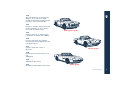
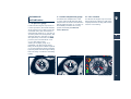
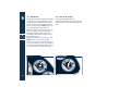
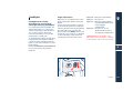
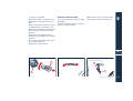
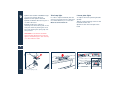
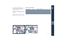
3500 Vignale spyder
1989
Shamal is the first car featuring the
new Biturbo 8-cylinder with 3200 hp.
1993
Fiat Auto purchases the complete
share package and in 1998 presents the
new Quattroporte.
1997
Ferrari acquires the control of
Maserati.
Mistral spyder
1998
Quattroporte Evoluzione V8 3.2 - V6
2.8.
3200 GT V8.
1999
3200 GT V8 Automatica.
2000
The Officine Alfieri Maserati program.
Ghibli spyder
Historical Background
5
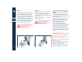
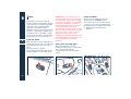
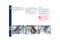
Introduction
Consulting the Manual
To facilitate reading and rapid use, the
topics are subdivided into SECTIONS
and CHAPTERS.
The important parts requiring
particular attention are easily
identifiable in the sections and
chapters.
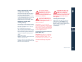
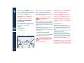
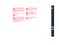
EXTREME CAUTION
REQUIRED: non-compliance
with the instructions can
cause SERIOUS DANGER involving the
safety of persons and damage to the
vehicle!
WARNING warning to prevent any
damage to the vehicle and thus
hazards involving the safety of
persons.
6
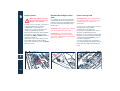
Introduction
Abbreviations
Updating
Some descriptions and terms with
particular meanings are found in this
manual in an abbreviated form:
A.C. - AIR CONDITIONING
ABS - ANTILOCK BRAKING SYSTEM Wheel locking prevention
system during braking
ASR - ANTI SLIP REGULATION Prevention of skidding during
acceleration
EBD - ELECTRONIC BRAKE-FORCE
DISTRIBUTION - Electronicallycontrolled distributor of
braking force
ECU - ELECTRONIC CONTROL UNIT
MSP - MASERATI STABILITY PROGRAM
Yaw prevention monitoring
system
“Cambiocorsa” - Electronically
controlled gearbox.
The vehicle's high quality level is
guaranteed by constant
improvements. Therefore, there may
prove to be differences between this
manual and your vehicle.
All specifications and illustrations
contained in this manual refer to those
resulting as of the printing date.
Service
“Cambiocorsa" gearbox
The information contained in this
manual is limited to those instructions
and indications that are strictly
required for the use and good
preservation of the vehicle.
The Owner will certainly obtain
greater satisfaction and the best
performance from the vehicle by
following these instructions carefully.
We also advise you to have all the
maintainance and checking
procedures carried out at the Maserati
Service Network, as this Network has
specialized staff and suitable
equipment available.
See the Manual entitled "SALES AND
SERVICE NETWORK" for locations of
AUTHORISED MASERATI DEALERS AND
SERVICE CENTRES.
The Maserati Service Network is at the
Client’s complete disposal for any
information and suggestions required.
The vehicle can be equipped with a
mechanical gearbox system with dry
double-disk clutch, controlled by an
electro-hydraulic system using steering
wheel levers.
Although the system can be used in
"automatic" mode, the
"Cambiocorsa" should not be
considered as an automatic
transmission. Therefore, for correct
use, carefully follow the instructions in
the respective section of this manual.
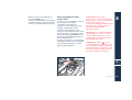
Introduction
7
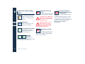
Symbols
There are specific colored plates on or
near some of the components on your
MASERATI. The related symbols are
important warnings that the user must
follow when using the particular
component at hand.
All of the symbols included in the
labelling on your MASERATI are listed
concisely here below, along with the
component involved with that symbol.
In addition, the meaning of the symbol
shown is also indicated in terms of the
following sub-division: danger,
prohibited, warning, compulsory with respect to that same symbol.
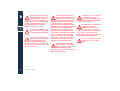
Danger symbols
Battery
Corrosive liquid.
Battery
Do not approach with naked
flames.
Battery
Explosion.
Battery
Keep children at a safe
distance.
Fan
Can start up automatically
even with the engine stopped.
Heat guards - belts - pulleys fans
Do not rest your hands on it.
Expansion tank
Do not remove the cap when
the coolant is hot.
Coil
High voltage.
Belts and pulleys
Moving members; Keep body
parts and clothing away.
Air-conditioning lines
Do not open. Gas under high
pressure.
8
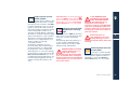
Symbols
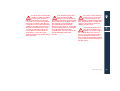
Symbols of prohibitions
Warning symbols
Catalytic muffler
Do not park or stop over
flammable surfaces. Refer to
section: “Pollution control
devices”.
Hydraulic steering
Do not exceed the maximum
level of fluid in the tank. Only
use lubricants of the type
prescribed in the chapter
“Capacities and technical
specifications”.
Brake circuit
Do not exceed the maximum
level of fluid in the tank. Only
use fluids of the type
prescribed in the chapter
“Capacities and technical
specifications”.
Windshield wiper
Only use fluids of the type
prescribed in the chapter
“Capacities and technical
specifications”.
Engine
Only use lubricants of the type
prescribed in the chapter
“Capacities and technical
specifications”.
Symbols indicating compulsory
measures
Battery
Protect your eyes.
Battery - Jack
Refer to the Owner's Manual.
Vehicle using lead-free
gasoline
Only use lead-free gasoline
with an octane number
(R.O.N.) of no less than 95.
Expansion tank
Only use fluid of the type
prescribed in then chapter
"Capacities and technical
specifications".
Symbols
9
10
Symbols
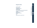
General contents
Car identification data
1
Active and passive safety
2
Instruments and controls
3
Before you drive
4
Using the vehicle
5
In an emergency
6
Capacities and technical specifications
7
Maintenance
8
Contents
9
Symbols
11
12
Symbols
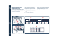
Car identification data
Identification plates (European version)
Identification data (European version) summary plate
Key codes
Electronic anti-theft device code
14
15
16
17
Symbols
1
13
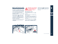
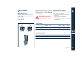
Identification plates
(European version)
Chassis marking
1
The vehicle's registration number is
punched on the dashboard panel in
front of the passenger seat.
To read this number, lift the mat and
open the flap A.
Engine marking
Paint identification plate
The registration number B is punched
on the cylinder block and includes the
type and serial number.
The engine type is also given on the
summary plate located on the front
crossmember of the car.
The plate C is applied to the bonnet.
A
C
B
14
Identification plates (European version)
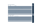
Identification data
(European version)
summary plate
The plate is applied in the engine
compartment, on the front
crossmember and gives the following
data:
G - Maximum admissible weight on
second (rear) axle
H - Engine type
I - Vehicle version code
L - Assembly number.
1
A - Manufacturer's name
B - Type approval number
C - Identification code of the
manufacturer (ZAM) and type of
basic vehicle
D - Serial number
E - Maximum admissible weight
F - Maximum admissible weight on
first (front) axle
A
E
F
G
B
C
I
D
H
L
Identification data (European version) summary plate
15
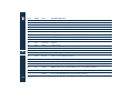
Key codes
1
A CODE CARD is supplied with the
keys. This card indicates the following:
– the electronic code A to be used for
“emergency starting”
– the mechanical code B for the keys,
to be given to the Maserati Service
Network in the case that you request
duplicates of the keys.
A
B
16
Key codes
WARNING The code numbers shown
on the CODE CARD must be kept in a
safe place.
WARNING You are advised to always
keep the CODE CARD number with
you, because it is absolutely necessary
in the event of “emergency starting”.
WARNING In the event of a vehicle
ownership transfer, it is essential that
the new owner is provided with all the
keys and with the CODE CARD.
WARNING It is advisable to write down
and keep the codes listed on the plates
delivered with the keys and the remote
control in a safe place (not in the car)
in order to request duplicates if
needed.
Electronic anti-theft
device code
Rolling Code
1
Each time the radio operated control is
used, the code changes.
Keep the plate with the Rolling Code
with care and in a safe place. To order
extra keys fitted with radio operated
controls, contact your Maserati Service
Network indicating your complete
Rolling Code.
Electronic anti-theft device code
17
18
Electronic anti-theft device code
Active and passive safety
Seat belts
Safe transport of children
Front and side airbags
MSP System
ABS and EBD systems
ASR system (electronic anti-skid device)
Parking sensors (optional)
Fire extinguisher (optional)
Fuel cut-off inertia switch
20
24
30
37
38
40
41
44
45
2
19
Seat belts
2
The vehicle is equipped with seat belts
with automatic retractor for maximum
freedom of movement.
The seat belts are equipped with
electronically-operated pretensioners
and the lower attachments points are
connected directly to the seat, to
guarantee maximum protection
whatever the seat position.
Before fastening the seat
belts make sure they are
correctly fitted into the guide
A on the seat.
The passenger seat belt (US version
only) is fitted with the KISI system,
which improves safety when children
are travelling in special child seats. The
system is activated by pulling out the
belt to its full length: once the child
seat is securely fastened, the belt can
no longer be pulled out and hence the
belt/child seat system is exceptionally
secure. When the belt is released and
fully retracted, the system deactivates
and resumes its normal operation.
Fastening the seat belts
After recovering the lower part of the
seat belt from the external side of the
seat, grasp the connection tab to
fasten the belt B and pull the seat belt
out until the tab is fully inserted in the
buckle C.
The belt is correctly engaged when the
lock clicks into position. Press the
button D to release the seat belts..
If the driver's seat belt is not fastened,
when the ignition key is rotated into
position MAR, the < warning light on
the instrument panel will switch on
and a buzzer will activate for
approximately 8 seconds.
The retractor locking device is
activated whenever the belt is pulled
out too rapidly or in case of sudden
braking or collision.
If the belt locks due to too rapid
extraction, allow it to retract a short
distance to disengage the locking
device.
The retractor allows the belt to
automatically fit to the passenger’s
body, allowing him to move freely.
When the vehicle is parked on a steep
slope, the retractor may lock: this is
normal.
WARNING Feed the belt back into the
retractor by hand to avoid twisting and
snagging.
B
A
C
D
20
Seat belts
Load limiting devices
To increase the passive safety, the seat
belt retractors are equipped with load
limiting device which makes it possible
to control the belt reeling out so that
the force exerted on the shoulders
while the seat belt is in restraining
mode can be limited.
Pretensioners
To make the seat belts still more
efficient, the vehicle is equipped with
pretensioners.
These devices "are notified" by a
sensor that the vehicle is in a collision
and retract the belts by a few
centimeters. This ensures that the belt
perfectly adheres to the occupants’
bodies before it brakes their forward
motion.
When the belt locks, this indicates that
the pretensioners have been activated;
a small amount of smoke may be
visible.
The smoke is not toxic and is not
indicative of fire.
Following the pretensioner activation,
the seat belt can be normally released
by pressing the button on the buckle.
The pretensioners do not require
maintenance or lubrication.
Tampering with the devices will
compromise their efficient operation.
If, as a result of exceptional natural
circumstances (floods, heavy seas, etc.),
the device has been in contact with
water and sludge, it is absolutely
essential to replace it.
To ensure the best protection from the
pretensioners, secure the belt snugly
across your chest and pelvis.
The pretensioners will
operate only once, and will
operate even if the belts are
not fastened. Therefore, they must be
replaced by the Maserati Service
Network after operation. The units
have a ten year service life from the
date of manufacture; they must be
replaced when their service life is near
to expiry.
WARNING Work on the vehicle which
involves blows, vibrations or localized
heating (over 100°C for 6 hours max.)
in the area of the pretensioners may
damage or activate them: vibrations
due to bad road surfaces or mounting
the pavement, for instance, do not
affect the units. Please contact the
Maserati Service Network if
interventions must be carried out.
2
Do not tamper with the
pretensioner components.
Any intervention must be
carried out only by qualified and
authorized personnel. Always contact
Maserati Service Network.
Seat belts
21
General warnings regarding the
seat belts
The driver is obliged by law to
respect and enforce the
provisions of local legislation
regarding the compulsory use of seat
belts.
2
To guarantee maximum
protection, you are advised to
keep the seatback in the most
upright position possible and the seat
belt close to your chest and pelvis. If
the seat belt is loose, in the event of
an accident you would be move too
far forward and could be injured.
Travelling with the seatback too far
reclined could be dangerous: even if
the seat belts are fastened, they may
not work correctly. In fact, the belt
itself may not be close enough to your
body and, if it is in front of you, it
could cause neck wounds or other
injuries in an accident. What is more,
in an accident, the lower section of the
belt could press against the upper part
of your stomach rather than the pelvic
area, causing serious internal injuries.
Always fasten the seat belts.
Traveling without the seat
belts fastened increases the
risk of injury in the event of a collision,
22
Seat belts
even with the airbags. In the event of
a collision, the seat belts reduce the
possibility of the vehicle's occupants
being thrown against the parts of the
passenger compartment or out of the
vehicle. The airbags are designed to
work together with the seat belts, not
to substitute them. The front airbags
only intervene in the event of head-on
collisions of medium or high intensity;
They will not be activated if the
vehicle rolls over, or in the event of
rear or low intensity frontal collisions.
Do not fasten your seat belt
using the buckle for the other
seat: in the event of an
accident, the lower section of the belt
could press against the upper part of
your stomach rather than the pelvic
area and cause you serious internal
injuries.
It is extremely dangerous to
travel with the belt positioned
underneath your arm. In the
event of an accident you would be
thrown forward and would very
probably suffer head and neck
injuries. What is more, if the belt
presses against your ribs, it could
cause serious internal injuries.
The belt itself must not be
twisted; make sure that it is
snugly fitted to the occupants’
bodies. In fact, in an accident, the
restraining force would not be
distributed evenly across the belt and
would consequently cause injuries.
The upper section of the belt must be
correctly fitted in the seat guide and
pass over the shoulder and diagonally
over the chest. The lower section must
be adhere to your pelvis, not the
stomach, to avoid sliding forward in
case of collision. Do not use devices
(clamps, fasteners etc.) to hold the
seat belts away from the passengers'
bodies.
Do not carry children on a
passenger’s lap using only one
seat for both of them.
If the seat belt has been
subjected to strong
mechanical stress, for
example during a collision, it must be
completely replaced together with its
anchorages, the anchor point screws
and the pretensioner. In fact, even if
there are no visible defects, the seat
belt could have lost some of its
resistance.
Pregnant women must
scrupulously observe local
legislation regarding the use
of seat belts. Make sure in any case
that the lower section of the belt is
secured well down on the hips, below
the abdominal region of the body.
Safe use of the seat belts
1) Always use the seat belts with the
belt completely flat, not twisted; Make
sure the belt can move freely and is not
obstructed by anything.
2) The seat belts must be replaced any
time the pretensioners are activated or
whenever the belt is clearly damaged
or worn.
3) Wash the seat belts by hand using
water and Ph neutral soap, rinse them
and allow them to dry in the shade. Do
not use strong detergents, bleaches,
colorants or other chemicals which
may weaken the belt fabric.
4) Make sure the retractors do not get
wet: they are only guaranteed to work
correctly if kept dry.
Seat belts
2
23
Safe transport of children
2
For the best protection in the event of
a collision, all the vehicle's occupants
must travel seated and protected by all
the suitable restraining systems. The
seat belts are designed to be used by
persons whose physical characteristics
(age, height, weight) are provided for
by established legislation in each
country. Anyone who does not comply
with these provisions may not travel in
the passenger seat.
This also applies to children. Their
heads are proportionally heavier and
larger than those of adults, while their
bones and muscles are relatively
undeveloped. For children to be
restrained correctly in the event of a
collision, suitable restraining or safety
systems must be used.
Children must never travel
seated on a passenger's lap. A
child weighs very little until a
collision occurs! In a collision, a child
becomes so heavy it is impossible to
hold onto him or her. For example, in a
collision at only 25 mph (40 km/h), a
child weighing 12 lb. (5.5 kg) exerts a
force of 240 lb. (110 kg) against the
arms of the person holding him or her.
Children must always be protected by
a suitable restraining system when
travelling.
Children who are resting on
the airbag or are too close to it
when it is activated, may be
seriously injured. The airbags and
pretensioners offer suitable protection
for adults and teenagers, but not for
children and babies. Neither the seat
belts or the airbags are designed for
them. Children and babies must travel
in suitable restraining systems.
Babies must be supported
completely, including their
head and neck. This is
necessary because a baby's neck is
weak while the head is much bigger
and heavier in proportion to his/her
body. In a collision, if a baby is
travelling in a backwards-facing seat
the forces of an impact are distributed
throughout the more solid parts of the
body, i.e. the back and shoulders.
Babies must always be protected by a
suitable restraining system when
travelling.
A child traveling in a
backwards-facing seat could
be seriously injured by an
airbag being activated. This could
happen because the seat back of the
child's seat may be positioned
extremely close to the airbag at the
moment it is inflated.
Check that the airbag has
been deactivated before
positioning a backwardsfacing child's seat on the passenger
seat.
24
Safe transport of children
The structure of a child's body
is completely different from
adult's or a teenager's (who
the seat belts are designed for). A
child's hips are so small that seat belt
will not stay in the correct position on
them. The belt may rise up on the
child's stomach and, in the event of a
collision, cause serious internal
injuries. Even children must always be
protected by suitable restraining
systems.
All minors whose physical
characteristics (age, height, weight)
meet the limit values provided by the
established legislation in each country
must be protected by special restraint
or safety systems (certified child seats,
cradles, cushions).
Make sure to use certified universal
child restraining systems.
Follow the manufacturer’s installation
and user instructions for child
restraining systems, as supplied with
the equipment itself.
To guarantee the best
restraining function of the
child seat, we advise to
choose the model which better suits
the passenger seat shapes. Before
purchasing a child seat, we
recommend to try installing it on your
car.
In the event of an accident , a
badly fastened child
restraining system increases
the risk of injury.
2
When installing the child seat,
the car seat must be
positioned completely
backwards and downwards. This is
indispensable for guaranteeing the
maximum protection of the child.
Safe transport of children
25
2
Backwards-mounting child
seats must not be used on
front passenger seats
equipped with active airbags, as these
could cause serious injury during
inflation, even in minor collisions.
Backwards-mounting child seats can
be used on the front passenger seat
only in European models, which are
provided with the airbag de-activation
switch. In this case, it is absolutely
essential to make sure, by checking
the F warning light on the
instrument panel, that the airbag has
been deactivated.
On no account must any
modifications be made to the
seat belts and the child
restraining systems. Established
legislation in some countries already
provides that children under 12 years
of age may not travel in the front
passenger seat.
26
Safe transport of children
As for the European model, the results
of research into child passenger safety
are embodied in the European
standard ECE-R44, which not only
makes the use of special restraint
system compulsory, but divides such
equipment into four categories:
Group 0 0-10 kg passenger weight
Group 1 9-18 kg passenger weight
Group 2 15-25 kg passenger weight
Group 3 22-36 kg passenger weight
As can be seen, the groups partially
overlap and commercially available
equipment may cover more than one
weight group.
All the restraining devices must bear
the approval data, together with the
check mark on a plate - which must
never be removed - fixed soundly to
the device.
Over 36 kg weight and 1.50 m height,
children, for the purposes of restraint
systems, are considered equivalent to
adults and wear seat belts in the
normal way.
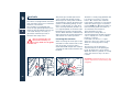
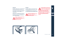
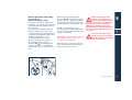
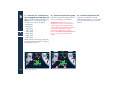
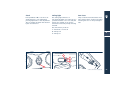
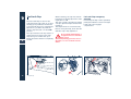
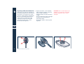
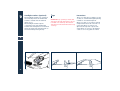
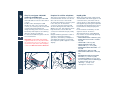
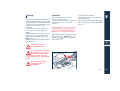
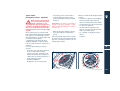
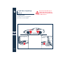
Group 0
Group 1
Children weighing up to 10 kg must be
transported facing to the rear on a
rocker-style child seat, which provides
head support for protection against
neck strain in case of sudden
deceleration.
The rocker is secured by the vehicle’s
seat belts as shown in the figure, and
must itself restrain the child with its
own integrated belts.
Children weighing over 9 kg must be
transported facing forwards in a child
seat equipped with a front cushion
into which the vehicle seat belt is fitted
to secure both the seat and the child.
Figures are purely illustrative.
Secure the child seat
according to the instructions
provided with the product.
Certain child seats meet the
requirements for groups 0 and
1 with a rear fixing point for
the seat belt and integrated harness
for child restraint. Due to their
weight, they may be hazardous if
incorrectly secured to the vehicle seat
belts with a cushion. Follow the
instructions provided with the
product.
2
Figures are purely illustrative.
Secure the child seat
according to the instructions
provided with the product.
Safe transport of children
27
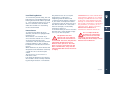
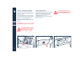
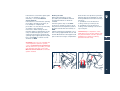
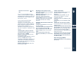
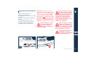
Group 2
2
Children weighing over 15 kg must be
secured directly by the vehicle seat
belt. The child seats have the sole
function of correctly positioning the
child with respect to the belt, in such a
way that the diagonal section of belt
fits snugly against the chest rather
than the neck and the lower horizontal
section of the belt fits against the
pelvis rather than the stomach.
Figures are purely illustrative.
Secure the child seat
according to the instructions
provided with the product.
Group 3
Children weighing over 22 kg need
only use a cushion to raise their
position. The depth of the child’s chest
is sufficient to make a distancing back
rest unnecessary.
Children over 1.50 m in height can use
seat belts like adults.
Figures are purely illustrative.
Secure the child seat
according to the instructions
provided with the product.
To summarize, the following safety
regulations apply to the transport of
children:
If the car is equipped with active
passenger airbags, children may not
travel on the front seat in a backwardsmounted child seat.
When the passenger's airbag should
be deactivated, always check the
relevant warning light F on the
instrument panel to ensure it has
actually been deactivated.
Always and strictly follow the
instructions which the manufacturer is
obliged by law to enclose with the
seat. Keep the instructions in the
vehicle together with the documents
and this handbook. Do not use a seat
which does not have any instructions
for use.
WARNING We advise to choose the
child seat model which better suits the
passenger seat shapes and, before
purchasing any child seat, we
recommend to try installing it on your
car.
Always pull on the seat belt to check
that it is locked in.
All restraint system is for use by a
single passenger only: Never carry two
children in the same seat.
Always check that the seat belts are
not resting against the child's neck.
28
Safe transport of children
Do not allow the child to assume
incorrect positions or undo the seat
belt /child seat safety harness during
travel.
Do not carry children in your arms,
even new born children. Nobody,
however strong, can hold on to a child
in the event of a collision.
After an accident, always replace the
child's seat with a new one.
2
Safe transport of children
29
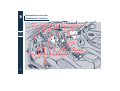
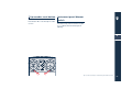
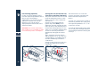
Front and side airbags
11
2
2
1
3
4
6
8
10
5
30
Front and side airbags
7
9
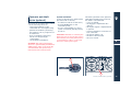
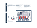
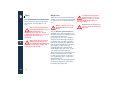
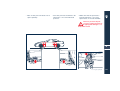
The vehicle is equipped with 4 airbags
(2 frontal and 2 side) and
electronically-operated pretensioners.
The system components connected to
the ECU are as follows:
1) Electronic Control Unit
2) Driver's frontal airbag
3) Passenger's frontal airbag
4) Airbag cut-out switch (not included
on the US version)
5) Driver's side airbag
6) Passenger's side airbag
7) Left-hand seat belt pretensioner
8) Right-hand seat belt pretensioner
9) Left-hand satellite sensor
10) Right-hand satellite sensor
11) Air bag system failure warning
light
Front airbags
The frontal airbags (for the driver and
passenger) are safety devices which
intervene in the event of a head-on
collision.
It consists of an instantaneously
inflating bag contained in a special
housing:
– in the center of the steering wheel
on the driver side;
– in the dashboard and with a larger
size bag (full size airbag) on the
passenger side.
The frontal airbags (for the driver and
passenger) are safety devices designed
to protect the occupants in the event
of a medium or high intensity head-on
collision, which act by placing a
cushion (bag) between the occupant
and the steering wheel or the
instrument panel dashboard.
In the event of a collision, an ECU
processes signals from a deceleration
sensor and triggers, whenever
necessary, the inflation of the bag.
The bag inflates instantaneously
between the front passengers and
potentially harmful structures. The
bag deflates immediately afterwards.
Front and side airbags
2
31
2
32
In the event of a collision,
anyone not wearing a seat
belt will be thrown forward
and will come into contact with the
bag before it is fully inflated. This
reduces the protection offered by the
bag. It follows that the front airbags
(driver and passenger side) do not
replace or substitute the seat belts but
complement them, and hence the seat
belts must always be worn as
provided by established European
legislation and in most other parts of
the world.
Front and side airbags
In case of low impact head on collisions
(in which the retaining action of the
seat belts affords adequate
protection), the airbags do not inflate.
In case of rear collisions (e.g. impact
from behind by another vehicle) and
side collisions, the airbags do not
inflate as they do not offer any
additional protection.
Therefore the bag's failure in these
cases is not an indication of a system
malfunction.
Passenger side airbag
(full size airbag)
The passenger side airbag is designed
to afford supplementary protection to
a person wearing the seat belt.
It therefore inflates to fill the larger
part of the space between the
occupant and the dashboard.
SERIOUS HAZARD: the
vehicle is fitted with a
passenger side airbag.
Before mounting a child seat on the
passenger seat, always de-activate the
passenger side airbag. Even where not
required by the law, we recommend
for the safety of adult passengers that
the airbag be immediately reactivated as soon as the seat is no
longer in use for child transport.
Manual passenger side airbag
de-activation
(European models only)
If a child is to be transported in the
passenger seat, always de-activate the
passenger side airbag before fitting
the child seat.
This can be de-activated, when the
vehicle's ignition key is in position,
using the relevant key-operated switch
located on the right-hand side of the
dashboard. The switch is only
accessible with the door open.
The key switch has two positions:
1) Passenger airbag activated:
(position ON P) instrument panel
warning light off; it is forbidden to
transport children on the passenger
seat.
2) Passenger airbag deactivated:
(position OFF F) instrument panel
warning light on; children protected
by appropriate restraint systems may
be transported in the passenger seat.
The F warning light on the
instrument panel remains switched on
continuously until the passenger side
airbag is reactivated.
WARNING Passenger side front airbag
de-activation does not affect the
operation of the side bag.
When the passenger side
airbag is cut out, because a
person considered by the laws
in force to be at risk is travelling and
must therefore be protected by an
additional restraining system, the
passenger will not have the additional
protection of the airbag in the event
of a collision.
2
Only deactivate the airbag
when a person at risk is being
carried, and always reactivate
it at the end of the journey.
When the door is open, the ignition
key can be fitted and removed from
the switch in both positions.
Front and side airbags
33
Side airbags (side bags)
2
34
The side airbags improve occupant
protection in case of moderate to
severe lateral collision.
They consist of instantaneously
inflating bags housed in the door
panels.
In case of lateral collision, the
electronic control unit processes the
signals from the two satellite sensors
mounted near to the rear wheelhouse
to determine the local acceleration
and it activates the side air bag if
necessary. This inflates by bursting
through the special seam in the door
knob.
The bag inflates instantaneously
between the passenger body and the
door. It then deflates immediately.
Front and side airbags
In case of low impact lateral collisions
(for which the retaining action of the
seat belts affords adequate
protection), the airbags do not inflate.
It follows that the front airbags (driver
and passenger side) do not replace or
substitute the seat belts but
complement them, and hence the seat
belts must always be worn as provided
by established European legislation
and in most other parts of the world.
The side bags are not de-activated
when the front passenger airbag is deactivated with the key switch, as
described in the preceding section.
Thus even children being transported
in the front passenger seat are
protected from lateral collisions by the
side bags.
WARNING The front and/or side
airbags may inflate if the vehicle
suffers a violent impact beneath the
car body, for example when mounting
the pavement, colliding with steps or
speed bumps, potholes etc.
WARNING Airbag inflation releases a
small amount of powder. This powder
is not harmful and does not indicate
the presence of fire; furthermore the
surface of the deployed bag and the
interior of the vehicle may be covered
with a powdery residue: this powder
may irritate skin and eyes. If contact
occurs, wash with a pH neutral soap
and water.
If the
warning light
switches on when the vehicle
is running (indicating a fault),
contact the Maserati Service Network
in due time to have the system
checked.
WARNING The airbag system has a
service life of ten years. When this
expiry date is approaching, contact
the Maserati Service Network.
In case of a collision with
consequent airbag inflation,
contact Maserati Service
Network for replacement of the entire
safety system, electronic control unit,
seat belts, pretensioners, and to have
the vehicle’s electrical system checked.
All testing, repairs and
replacements of the airbag
system must be done by
Maserati Service Network.
WARNING To scrap the vehicle, please
contact the Maserati Service Network
to have the system deactivated.
WARNING If the vehicle is sold, the
new owner must be informed of how
to use the vehicle and of the aforesaid
warnings and he must also get hold of
the "Owner's Manual".
The electronic control unit
activates the pretensioners
and front/side airbags on the
basis of different criteria according to
the type of collision. Failure of one or
the other system to activate is not
indicative of system malfunction.
General warnings
When the ignition key is
rotated to the MAR position
the
warning light
switches on, but it should switch off
after approximately 5 seconds. If the
light fails to come on at this time, or
stays on, or lights up when driving,
contact Maserati Service Network
immediately.
2
When the ignition key is
rotated to the MAR position
the warning light F (with
the deactivation switch passenger side
frontal airbag in position ON) switches
on for approximately 4 seconds, then
flashes for the next 4 seconds to
remind the occupants that the
passenger side airbag will be activated
in the event of a collision, after which
it switches off.
Under no circumstances
remove the steering wheel;
this procedure, if necessary,
must be carried out by a Maserati
Service Network operator.
Front and side airbags
35
Drive with both hands on the
steering wheel so that if the
airbag inflates it can do so
freely without encountering obstacles
which can cause serious injuries. Do
not drive with the body curved
forwards but keep the seat back
upright to support your back.
2
Do not apply stickers or other
objects to the steering wheel
or the passenger side airbag
housing.
Do not travel with objects in
your lap, in front of your chest
or especially with a pipe,
pencil or other object held in your
mouth; in the event of a collision, the
intervention of the airbag could result
in serious injury.
36
Front and side airbags
Note that with the ignition
key inserted and turned to the
MAR position, even with the
engine switched off, the airbags can
inflate even if the vehicle is stationary,
if it is run into by another vehicle.
Thus, even with the vehicle stationary,
children must be seated in the specific
restraint systems mounted on the
passenger seat, and the passenger
airbag must be deactivated. On the
other hand, the airbags will not inflate
in case of collision with the vehicle
stationary if the key is not inserted
and turned; failure of the airbags to
inflate in these circumstances is not
indicative of system malfunction.
If the vehicle has been the
object of theft or attempted
theft, if it has been vandalized
or involved in flooding, contact
Maserati Service Network to have the
airbag system checked.
If interventions are carried out
on the electrical system
incorrectly, the airbag could
be activated, thereby causing injuries
to anyone in the vicinity.
The airbags do not replace the
seat belts but afford
supplementary protection.
Furthermore, in case of low impact
head on or side collisions, rear impact
or roll-overs, the passengers are
protected exclusively by the seat belts,
which must always be secured.
Do not wash the door panels
with water or pressurized
vapor.
MSP System
The vehicle is equipped with an MSP
(Maserati Stability Program) yaw
prevention monitoring system
encompassing all of the vehicle's
control systems: ABS, EBD, ASR and
MSR. It has a model within it that
predicts the vehicle's behaviour with
extreme accuracy. The system is
capable of detecting whether the
driver is about to lose control of the
vehicle. In this case, it can activate the
brake calipers individually and engine
control, in order to create a torque
sufficient to resist the vehicle's yawing
moment.
Activating the MSP system
The MSP system is automatically
enabled each time the engine is
started. During the activation phases,
the initials MSP switch on in green on
the multi-function display. To disable
it, press button A for about 2 seconds.
When the system is disabled, the
initials, on the multi-function display
and the LED on the button light up.
Press button A to switch on the system
again: the warning light on the multifunction display and the button led go
off.
Fault signals
In the event of a fault, the system is
automatically disabled and cannot be
re-activated. When driving, this
condition is signalled by the LED on the
button switching off and by the
initials lighting up on the multifunction display. When the engine is
started, any system malfunction is
signalled by the
initials lighting
up on the multi-function display.
WARNING In the event of a
malfunction with the MSP disabled,
the vehicle will react as if it were not
equipped with this system. In any case,
have the MSP system checked at the
Maserati Service Network as soon as
possible.
WARNING If you have to tow the car
with 2 wheels raised, ensure that the
ignition key is in the STOP position.
Otherwise, with the MSP switched on,
the respective control unit stores a
malfunction in the memory resulting
in the
initials lighting up on the
instrument panel, which requires the
intervention of the Maserati Service
Network for resetting of the system.
2
WARNING In low grip conditions
(when there is ice, snow, sand etc.) It is
advisable not to use the SPORT mode
function, even with the MSP enabled.
A
MSP System
37
ABS and EBD systems
2
38
The vehicle is equipped with ABS
(Antilock-Blocking System) and EBD
(Electronic Brakeforce Distribution)
systems which, via the ECU and the ABS
sensors, increase the braking system's
performance.
In the event of an emergency stop or
braking on slippery surfaces (where
there is snow, ice etc), the ABS,
together with the conventional
braking system, allow the driver to
apply maximum braking force without
the wheels locking and the driver
consequently losing control of the
vehicle.
The system is based on an ECU which
processes the signals transmitted by
the 4 sensors located on the 4 wheels.
When a wheel is tending to lock, the
sensor warns the ECU which, in turn,
informs to the electro-hydraulic unit to
intervene by modulating the pressure
exerted on the brake calipers; The
driver will feel a 'pulsing' sensation
coming from the brake pedal, which is
quite normal.
In the event of a failure, the system will
be deactivated, but this will not affect
the efficiency of the standard braking
system.
ABS and EBD systems
The failure is indicated by the red
warning ABS > switching on on the
instrument panel.
In this case, we recommend you
contact the nearest Maserati Service
Network workshop, which, thanks to
the self-diagnostics system the vehicle
is equipped with, will be able to
identify the problem immediately.
The vehicles must be fitted
with wheel rims, tires and
brake lining of the kind and
make approved for this model by the
manufacturer.
Although this device
contributes greatly to the
vehicle's safety, it is still
essential to drive with particular care
when the road is wet or there is snow
or ice on the ground.
The vehicle is equipped with
the EBD (Electronic Brakeforce
Distribution) system. If the
warning light
switches on when
the engine is running, this indicates a
malfunction in the EBD system; in this
case sharp braking could lead to the
rear wheels locking too early, and the
vehicle may skid. Driving extremely
carefully, go straight to the nearest
Maserati Service Network workshop
to have the system checked.
If only the > warning light
switches on while the engine
is running, this normally
indicates a malfunction in the ABS
only. In this case, the braking system
maintains its efficiency, but the antilocking device cannot be used. In these
conditions the EBD system may also
function less efficiently. Also in this
case we recommend you go to the
nearest Maserati Service Network
immediately to have the system
checked, avoiding any sharp braking
while you drive.
If the minimum brake fluid
level warning light
switches on, stop the vehicle
immediately and check the brake fluid
level in the tank: if the level is below
the minimum, top it up with the
prescribed fluid and contact the
Maserati Service Network to have the
system checked. In fact, any fluid leaks
from the hydraulic system will
jeopardize the operation of both the
standard braking and the ABS
systems.
The system's performance, in
terms of active safety, must
not lead the driver to run
futile and unjustified risks. The vehicle
must always be driven suitably with
regards to the weather conditions,
visibility and the traffic.
The maximum deceleration
that can be reached always
depends on the tires' grip on
the roadbed. Obviously, if there is
snow or ice on the road, the grip is
greatly reduced and therefore, in
these conditions the braking distance
is greater, even with the activation of
the ABS system.
2
ABS and EBD systems
39
ASR system (electronic
anti-skid device)
2
40
The ASR system prevents the driving
wheels skidding during acceleration
via the engine's ECU action (delayed
spark advance, reduced engine supply
throttle opening and injection cut-off)
and that of the rear brakes.
The ASR's action helps to increase the
stability and the vehicle's active safety
when it is running, especially in the
following situations:
– internal wheel skidding on curves
because of the dynamic variations of
the load or excessive acceleration
– excessive power transmitted to the
wheels, also in relation to the
roadbed conditions
– acceleration on slippery surfaces or
where there is snow or ice,
– in the event of loss of grip on wet
roadbeds (aquaplaning).
ASR system (electronic anti-skid device)
The ASR acts in combination with the
electronic suspension adjustment
system: in normal conditions (SPORT
mode disabled) stability is prioritized
in low and medium grip conditions,
while with the SPORT mode enabled
the system gives priority to the
traction, optimizing the vehicle's
performance and allowing it.
MSR function (engine braking
torque adjustment)
The ASR system also controls the
engine braking torque when the
accelerator pedal is released under low
grip conditions (snow, ice etc.): in these
conditions, in fact, the engine's high
braking torque may cause instability of
the vehicle.
The system, using the same sensors as
the ABS, detects the skidding arising
on one or both of the driving wheels
when the accelerator is released and
opens the engine supply motorized
throttle, therebt reducing the braking
torque and restoring the driving
wheels' maximum grip conditions.
WARNING However, the maximum
deceleration that can be obtained with
the engine brake still depends on the
tire grip on the roadbed. Obviously,
snow or ice on the road greatly reduce
the grip values.
Parking sensors (optional)
During parking maneuvers, the
parking sensors provide the driver with
information on the distance between
obstacles found behind the vehicle.
The information on the presence and
distance of the obstacle is transmitted
to the driver by warning beeps which
sound with an increasing frequency as
the car approaches.
By supplementing his/her direct visual
information with that provided by the
system's warning sound signals, the
driver can avoid potential collisions.
However, the driver remains
responsible during parking
maneuvers and in other
potentially dangerous situations. The
system has actually been designed
only as a supplementary aid during
parking maneuvers, since it allows the
driver to detect obstacles outside the
field of vision.
The parking system sensors, housed in
the rear bumper, are activated
automatically when the key is turned
to the MAR position and the reverse
gear is engaged. When the reverse
gear is engaged, a beep warns the
driver that the system is active. The
system then begins to beep as soon as
an obstruction is detected, with the
frequency increasing as the vehicle
approaches the obstacle.
When the obstacle is located at a
distance of less than 30 cm, the beep is
continuous.
The warning beep stops immediately
if the distance between the vehicle and
the obstacle increases. The tone cycle is
constant if the distance measured by
the central sensors remains unaltered,
while if this occurs with the lateral
sensors, the signal stops after
approximately 3 seconds, to prevent
for example continuous beeps in the
event of maneuvers alongside walls.
2
Sensors
To detect the distance of the obstacles,
the system uses 4 sensors housed in the
rear bumper.
For the system to operate
correctly the sensors
positioned on the bumper
must be kept clean (remove any mud,
dirt, snow or ice).
Parking sensors (optional)
41
2
42
WARNING When cleaning the sensors,
take special care not to scratch or
damage them; therefore, do not use
dry, rough or hard cloths. The sensors
must be washed with clean water,
possibly with car shampoo added. In
car-washes which use steam jet or high
pressure cleaning machines, keep the
nozzle at least 10 cm away from the
sensors.
Parking sensors (optional)
Sensor range
The sensors allow the system to
monitor the rear of the vehicle; in fact,
their position covers the central and
lateral zones at the rear of the vehicle.
If there is an obstacle located in the
central zone, it will be detected at
distances of less than 1.50 m.
If the obstacle is located in a lateral
position, it will be detected at
distances of less than 0.6 m.
Fault signals
The system's ECU runs all the checks on
the components every time the reverse
gear is engaged.
A parking sensor system failure is
indicated by a continuous warning
signal from the buzzer when the
reverse gear is engaged.
In the event of a failure signal, stop the
vehicle and rotate the ignition key to
the STOP position. Then try cleaning
the sensors or moving the vehicle away
from any possible ultrasound sources
(e.g. pneumatic truck brakes or
pneumatic hammers) and rotate the
ignition key to the MAR position. This
way, if the cause of the operating fault
has been removed, the system will start
functioning again automatically and
the failure buzzer will stop.
If however, the failure beep continues,
contact the Maserati Service Network
to have the system checked.
WARNING During parking maneuvers,
always take the utmost care over
obstacles that could be located above
or underneath the sensors. In fact, in
certain circumstances, objects located
near the rear of the vehicle are not
detected by the system and therefore
could damage the vehicle or be
damaged themselves.
WARNING The signals transmitted by
the sensors can also be altered by
damage to the sensors or by dirt, snow
or ice on the latter or even by
ultrasound systems (e.g. pneumatic
truck brakes or pneumatic hammers) in
the vicinity.
However, the driver remains
responsible during parking
maneuvers and in other
potentially dangerous situations.
When these maneuvers are
performed, always make sure there
are no people (especially children) or
animals in the maneuvering area. The
parking sensors must be considered an
aid for the drivee who, in any case,
must never take less care during
potentially dangerous maneuvers,
even if they are carried out at low
speeds.
Parking sensors (optional)
2
43
Fire extinguisher
(optional)
2
A portable fire extinguisher is located
on the passenger compartment floor
for immediate accessibility in case of
need. The extinguisher is fastened be
means of specific brackets.
Charged with powder, it has a 2 kgcapacity (8 second nominal discharge
time) and does not contain
chlorofluorocarbons.
Check the pressure and the charge
status using the pressure gauge A
regularly.
A
44
Fire extinguisher (optional)
The fire extinguisher must always be
fastened to its special brackets. If it is
not used, we recommend you remove
the entire device to free the passenger
foot area from the fire extinguisher
brackets.
WARNING To use the fire extinguisher,
follow the specific instructions
indicated on the device.
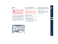
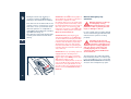
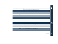
Fuel cut-off inertia switch
The vehicle is equipped with a safety
switch which intervenes in the event of
a collision, cutting off the fuel supply
and consequently causing the engine
to stop. It also prevents the fuel
spreading if the fuel lines are damaged
during the accident.
The intervention of the safety switch is
indicated by the
warning light
coming up on the instrument panel.
The switch is positioned inside the lefthand service compartment, in the
luggage compartment.
To gain access to the switch, open the
compartment hatch by pulling the
handgrip A.
After impact, if you smell fuel
or note any leakage from the
fuel supply system, do not
reactivate the switch in order to
prevent any fire risks.
Check that the
warning light on
the instrument panel is switched off.
Check once again that there are no
fuel leaks.
Resetting the switch
Rotate the ignition key to the STOP
position.
Check that there is no leakage from
the fuel system.
If no leaks are found, reset the inertia
switch which stops the fuel pump
operation, by pressing the button B on
the switch.
Rotate the ignition key to the MAR
position, wait for a few seconds and
then move it to the ACC. position.
2
B
A
Fuel cut-off inertia switch
45
46
Fuel cut-off inertia switch
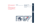
Instruments and controls
Dashboard (version with "Cambiocorsa" gearbox)
Dashboard (version with manual gearbox)
Instrument panel
Indicators and warning lights
Instruments and indicators
Trip recorder reset button
Instrument panel dimmer switch
Controls and interior equipment
48
50
52
54
57
61
61
62
3
47
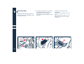
Dashboard (version with
"Cambiocorsa" gearbox)
14 15
1
2
3
4
5
6
7
8
9
10 11 12 13 14 15
3
16
17
18
19
20 21 22 23
32 35 34 36 33 30 29 28 27 19 26 24 25
31
48
Dashboard (version with "Cambiocorsa" gearbox)
1) Instrument panel
2) Lower gear activation lever DOWN
3) Interior temperature sensor
4) Driver’s airbag
5) Upper gear activation lever UP
6) Windshield/headlight wiper/washer
control lever (optional)
7) Upper ventilation and heating
outlet
8) Clock
9) Central air-conditioning and heating
vents
10) Fuel tank flap control button
(located in the glove compartment)
11) Luggage compartment lid control
button (in the glove compartment)
12) Passenger’s airbag
13) Glove compartment
14) Air conditioning and heating
system vents
15) Side windows vents
16) Emergency light switch
17) Info Centre display and controls
18) Ventilation and heating controls
19) Electric window controls
20) Handbrake lever
21) External rear-view mirror controls
22) Top open/close push-button
23) Ashtray and cigarette lighter
24) Pushbutton for “low grip” del of
the "Cambiocorsa" gearbox
25) Push button for "Cambiocorsa"
gearbox “automatic mode”
26) "Cambiocorsa" gearbox reverse
gear control lever
27) Switch unit
28) Starter/steering wheel lock switch
29) Lower air-conditioning/heating
vents
30) Horn control
31) Seat adjustment controls
32) Engine lid opening lever
33) Steering wheel height and depth
adjuster lever
34) Low beam height adjustment
control (excluding versions with
xenon-headlights)
35) External lights control
36) Cruise Control control lever
(optional), direction indicators and
low/high beam switch
3
Dashboard (version with "Cambiocorsa" gearbox)
49
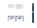
Dashboard (version with
manual gearbox)
12 13
1
2
3
4
5
6
7
8
9
10 11 12 13
3
14
15
16
17 18 19
28 31 30 32 29 26 25 24 23 22 21 20
27
50
Dashboard (version with manual gearbox)
1) Instrument panel
2) Interior temperature sensor
3) Driver’s airbag
4) Windshield/headlight wiper/washer
control lever (optional)
5) Upper ventilation and heating
outlet
6) Clock
7) Central air-conditioning and heating
vents
8) Fuel tank flap control button
(located in the glove compartment)
9) Luggage compartment lid control
button (in the glove compartment)
10) Passenger’s airbag
11) Glove compartment
12) Air conditioning and heating
system vents
13) Side windows vents
14) Emergency light switch
15) Info Centre display and controls
16) Gearshift lever
17) External rear-view mirror controls
18) Top open/close push-button
19) Ashtray and cigarette lighter
20) Handbrake lever
21) Electric window controls
22) Switch unit
23) Ventilation and heating controls
31) External lights control
32) Cruise Control control lever
(optional), direction indicators and
low/high beam switch
3
24) Starter/steering wheel lock switch
25) Lower air-conditioning/heating
vents
26) Horn control
27) Seat adjustment controls
28) Engine lid opening lever
29) Steering wheel height and depth
adjuster lever
30) Low beam height adjustment
control (excluding versions with
xenon-headlights)
Dashboard (version with manual gearbox)
51
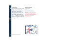
Instrument panel
3
4
5
6
7
8
9
10 11 12 13 14 15 16 17 18
3
23
2
19
24
1
20
26
25
27
32
52
Instrument panel
31
30
29
28
22
21
1) Oil pressure gauge and low pressure
warning light
2) Coolant thermometer and high
temperature warning light
3) Seat heating warning light
4) High beams warning light
5) Parking lights/low beams warning
light
6) Left-hand direction indicators
warning light
7) Air bag/pretensioners failure
warning light
8) Light failure warning light
9) EBD system failure warning light
10) EOBD engine control system failure
warning light
11) Catalytic converters' high
temperature warning light
12) ABS system failure warning light
13) Front brake pad worn/low brake
fluid warning light
14) Handbrake on warning light
15) Right-hand direction indicators
warning light
16) Maserati CODE system warning
light
17) Seat belts warning light
18) Passenger's airbag deactivated
warning light (European version only)
19) Voltmeter and generator warning
light
20) Fuel level gauge and low fuel
indicator
21) Rev. Counter
22) Instrument panel dimmer switch
23) Multi-function display
24) Doors, engine/luggage
compartment open display
25) Inertia switch activated warning
light
26) Front brake pad worn/low brake
fluid warning light
27) Indicator for "Cambiocorsa" gear
engaged / parking lights on
28) External temperature gauge
29) External temperature LED: it
switches on when the temperature is
equal to or lower than + 2 °C (icy road
surface hazard)
30) Electronic anti-theft device LED
31) Speedometer and distance trip
recorder
32) Trip recorder reset button
3
Instrument panel
53
Indicators and warning
lights
Seat heating (optional)
Indicates that the heating
device of one or both front
seats is turned on.
3
High beams
When the high beams are
turned on or flashing.
Parking lights/low beams
It switches on when the
dipped lights, low beams or
parking lights are turned on.
Direction
indicators
They switch on
when the direction lights or the hazard
warning lights are turned on.
54
Indicators and warning lights
Airbag/pre-tensioner
failure
When the pre-tensioner and/
or airbag system is defective.
Turning the key to MAR, the
light comes on but it should
go out after a few seconds
with the engine running.
If the light stays on or if it
does not come on or if it
comes on during running,
stop immediately and consult the
Maserati Service Network.
Light failure warning
light
It switches on in the case of
system failure or burning-out of the
bulbs for the parking, license plate,
stop or rear fog lights.
Electronic brakeforce
distribution (EBD) failure
warning light
It switches on when the EBD system is
defective.
In this case abrupt braking can cause
early locking of the rear wheels and
possible side skid of the car. Drive with
the utmost care and consult the
Maserati Service Network
immediately.
Engine control system
failure (EOBD)
Under normal conditions, the
warning light should switch on when
the ignition key is turned to the MAR
position and switch off as soon as the
engine is started. This will show that
the warning light is working properly.
If the warning light remains on or
switches on while driving, it indicates
that there is a failure in the fuel supply/
ignition and emission control systems.
The failure could cause high exhaust
emissions, loss of performance, poor
driving conditions and high
consumption levels.
Under these conditions you can
proceed slowly without demanding
engine performance or high speed.
Prolonged use of the car when the
warning light is on can cause damage.
For this reason, you should contact the
Maserati Service Network as soon as
possible. The warning light will go out
if the problem disappears. The error
will be stored by the system in any
case.
WARNING When you turn the ignition
key to the MAR position and the U
does not light up or switches on when
driving the car, contact the Maserati
Service Network as soon as possible.
Catalytic converter high
temperature warning
light
Turning the key to MAR the warning
light comes on for self-diagnosis, but
should go out after starting the
engine.
This warning light starts flashing or
comes on with a fixed light when
engine malfunction results in high
exhaust system temperature.
WARNING LIGHT FLASHING:
catalyst temperature is too
high. Reduce speed
immediately until the warning light
goes out and then drive carefully at
moderate speed. Contact the Maserati
Service Network as soon as possible to
remove the failure.
IF THE WARNING LIGHT
CONTINUES FLASHING OR
STAYS ON AFTER HAVING
REDUCED THE SPEED: dangerous
temperature in the catalytic
converters, catalysts can be damaged.
Stop the car immediately and have it
towed to a Maserati Service Network
workshop by a road service vehicle to
remove the failure.
Maserati declines all
responsibility for whatever
damage deriving from non
compliance with the above mentioned
warnings.
3
Defective wheel anti-lock
system (ABS)
It switches on when the ABS
system is defective. The normal brake
system remains operational, but it is
advisable to contact the Maserati
Service Network as soon as possible.
Indicators and warning lights
55
Front brake pads worn/
brake fluid low
It switches on when the front
brake pads reach the wear limit or the
brake fluid level drops below the
minimum level. The operation of the
warning light can be checked by
pressing the button on the brake fluid
reservoir cover located in the engine
compartment.
3
WARNING When replacing the front
brake pads, also check the rear brake
pads for wear.
If the warning light comes on
when the car is travelling
check immediately brake fluid
level. If fluid level is below the
minimum limit there could be a
leakage. Contact the Maserati Service
Network before restarting the car.
56
Indicators and warning lights
Handbrake on
The warning light flashes
when the handbrake is
operated.
Seat belts
It switches on when the
driver's seat belt is not
fastened or fastened incorrectly. A
buzzer is also activated for 8 seconds
when the light is on.
Maserati CODE
When the ignition key is
turned to the MAR position,
it may switch on under three possible
conditions:
– One flash - key code recognised. The
engine can be started.
– Fixed light - key code not recognised.
To start the engine, follow the
emergency starting procedure as
specified in the chapter "emergency
situations", after having attempted
to start it with other keys.
– Flashing light - vehicle not protected
by the Maserati CODE. The engine
can, however, be started but, contact
the Maserati Service Network as
soon as possible because the car is
not protected against attempts at
theft.
Passenger's airbag
deactivated (European
version only)
This warning light turns on when the
passenger’s airbag is deactivated.
Fuel shut-off inertia
switch on
It switches on when the
inertia switch has been activated
following a collision, thereby shutting
off the fuel supply.
After impact, if fuel is smelt or
leakage is noted from the fuel
system do not re-activate the
switch in order to prevent the risk of
fire.
Instruments
and indicators
1 – Oil pressure gauge
It indicates the engine oil pressure. In
normal operation, the needle must be
at the centre (2.5 to 5 bar). If it moves
towards 0 and at the same time the
warning light switches on, stop the car
and carry out the necessary checks. The
warning light also switches on when
the igntion key is turned to the MAR
position, but it should switch off as
soon as the engine starts.
A delay in the light going out is
permitted only when the engine is
idling. If the engine has been required
to work at maximum rate, the warning
light may flash with the engine idling
but it should go out when accelerating
lightly.
2 – Coolant temperature gauge
21 – Rev. Counter
It indicates the temperature of the
coolant. If the needle indicates high
temperatures and at the same time the
warning light switches on, stop the car
immediately and have the cooling
system checked by the Maserati
Service Network.
It indicates the engine's r.p.m. Correct
driving allows the driver to exploit the
engine performance fully, without the
need for over-revving.
3
Instruments and indicators
57
3
58
19 – Voltmeter
20 – Fuel level gauge
It indicates the battery voltage and the
consequent normal operation of the
charging system. With the battery in
good condition, with the engine off
and the starter key in MAR position, it
is located between 10V and 13V.
With the engine running the indicator
moves to values over 13V. The low
recharge warning light inside the
voltmeter indicates anomalies in the
recharging system.
When the starter key is turned to the
MAR position, the warning light
switches on, but it should switch off as
soon as the engine starts. Any delay in
its switching off with the engine idling
is not indicative of malfunctioning.
The warning light inside the
instrument switches on to indicate that
there are about 18 liters fuel left in the
tank.
Instruments and indicators
23 – Multi-function display
MSP
Switches on when the MSP
system is activated.
Indicates deactivation or
failure of the MSP system.
†
Indicates opening/closure
of the top or failure of the
top activation system.
SPORT
Indicates electronic
suspensions "sporty"
setting.
PWR
Indicates that the SPORT
mode is set for the
"Cambiocorsa" gearbox.
CRUISE
Indicates that the Cruise
Control is activated.
Indicates a failure in the
electronic suspensions
system.
v
Engine oil pressure
low.
t
Indicates a failure in the
“Cambiocorsa" gearbox.
)
Indicates windshield/
headlights washer fluid
low.
AUTO
Indicates that the
"automatic transmission"
mode is set for the
"Cambiocorsa" gearbox.
LEVEL
Indicates low
"Cambiocorsa" gearbox oil
level.
ICE
Indicates that the "low
grip" mode is set for the
"Cambiocorsa" gearbox.
24 – Doors and engine/luggage
compartment open display
Indicates that doors and bonnet/boot
are open or not properly closed.
3
Instruments and indicators
59
27 – Indicator for "Cambiocorsa"
gear engaged / parking lights on
When the ignition key is turned to the
MAR position, it indicates that the
"Cambiocorsa" gear is engaged:
– N (neutral)
– R (reverse)
– 1 (1st gear)
3
– 2 (2nd gear)
– 3 (3rd gear)
– 4 (4th gear)
– 5 (5th gear)
– 6 (6th gear)
When the key is removed, it indicates,
through the warning light F, that the
parking lights are on.
27
28 – External temperature gauge
29 – Outside temperature LED
Indicates the external temperature in
°C or °F, according to the market.
It switches on when the outside
temperature is equal to or lower than
+ 2 °C to indicate the risk of icy road
surfaces.
WARNING When the letter "E" is
displayed for several seconds (when
starting the engine and before the
outside ambient temperature appears)
it indicates a malfunction in the
heating/air-conditioning system.
Contact the Maserati Service Network
as soon as possible to remove the
failure.
27
29
60
Instruments and indicators
28
Trip recorder reset button
Press button A to set the trip recorder
to zero.
Instrument panel dimmer
switch
Turn button B, with the external lights
on, to adjust the instrument panel
lighting.
3
A
B
Trip recorder reset button / Instrument
panel dimmer
switch
Trip recorder
reset button
61
Controls and interior
equipment
Hazard warning lights
3
Press button A to turn on the hazard
warning lights. Their operation does
not depend upon the position of the
ignition key. Press the button again to
turn them off.
When these lights are on, the direction
indicators, the related warning lights
on the instrument panel and the
button are flashing.
Front fog lights
Press button B to switch on the front
fog lights. They only work with the
parking lights or dipped beam
headlights on. The LED on the
pushbutton switches on when the
lights are on.
Rear fog lights
Press button C to switch on the rear
fog lights. They only work with the
front fog lights or low beams on. The
LED on the pushbutton switches on
when the lights are on.
WARNING When the hazard warning
lights are activated, the direction
indicators control is disabled.
Do not use the rear fog lights
in normal visibility conditions
to avoid dazzling vehicles
behind.
A
B
62
Controls and interior equipment
C
D
Heated side window and sideview mirror defroster
Activation of the heated side window
and of the side rear view mirror
defroster is only possible when the
ignition key is in the MAR position and
by pressing button D. Although
activation of the heated side window is
timed, it is advisable to turn it off as
soon as the window is cleared of mist
or frost to avoid overloading the
battery. When the heated side window
is activated, the LED on the button
lights up.
WARNING To prevent the battery from
going flat, it is advisable to activate the
heated side window only when the
engine is running.
Opening the luggage
compartment
Press pushbutton E (located inside the
glove compartment) to open the trunk
lid.
Operation is possible only with the
ignition key removed or in the STOP
and ACC positions.
Opening the fuel tank flap
Press the F pushbutton (inside the
glove compartment) to open the fuel
tank flap on the right-hand rear side of
the car.
Operation is possible only with the
ignition key removed or in the STOP
position.
Low beam height adjuster
(excluding the version with
xenon-headlights)
It operates only with the ignition key
in the MAR position.
With the control turned upwards or
downwards G, the height of the low
beams varies for adjustment to the car
load.
WARNING The version with gas
(xenon)-emitting headlights is
equipped with a system that
automatically keeps the headlight
setting steady even with any variation
in the loads being transported.
E
3
F
G
Controls and interior equipment
63
MSP system
3
The MSP system is automatically
activated when starting the engine.
It is possible to disconnect or reconnect
the system during running by pressing
button H. To prevent inadvertent
deactivation, the button is to be
pressed for about 2 seconds for
deactivating the MSP system.
When the MSP system is on, the button
led is off, when the system is on the
MSP warning light on the multifunction display lights up.
When the system is off, the leds on the
pushbutton and the letters
on
the multifunction display light up.
H
64
Controls and interior equipment
Electronic setting of the
suspensions (optional)
Press button L to set suspensions in the
"Sport" mode.
When the "Sport" setting is on, the
LED on the pushbutton and the word
SPORT on the multi-function display
light up.
L
SPORT setting
On the "Cambiocorsa" gearbox
version, which does not feature the
suspension electronic setting mode,
the pushbutton M (PWR) activates the
gearbox SPORT setting, which enables
the car to reach its maximum
performance for a sport-type driving
on demanding tracks.
When the POWER function is selected,
the LED on the pushbutton and the
letters PWR on the instrument panel
light up.
If the car is equipped with electronic
setting for the suspensions, the
POWER function is switched on
automatically when the suspension
sport setting is selected.
M
Clock
Ceiling light
Sun visors
Press pushbutton N to set the clock:
slight pressure = slow adjustment
prolonged pressure = fast adjustment.
The clock lights up when the external
lights are turned on.
The ceiling light switches on
automatically when one of the doors is
opened and after a door is closed (the
switch-off is timed). It can also be
switched on manually or kept off using
switch P.
The switch has 3 positions:
1 – Automatic on and off
0 – Always off
2 – Always on.
They can be moved towards the front.
The courtesy mirror can be accessed by
lowering the visor on the passenger's
side.
3
P
1
0
2
N
Controls and interior equipment
65
3
Ashtray and cigarette lighter
Glove compartment
They are found on the central console
under a cover. Press the rear part to
open the cover.
Press button Q down to turn on the
cigarette lighter, which automatically
returns to its initial position and is
ready for use after 20 seconds.
Remove the tray in order to clean the
ashtray.
It is positioned in the lower part of the
dashboard on the passenger's side,
and the opening pushbutton R is
equipped with a lock. The
compartment is lit by a courtesy light
when it is opene.
WARNING Always check to ensure that
the cigarette lighter has been switched
off.
The cigarette lighter reaches
high temperatures. Handle it
carefully and do not allow
children to use it: risk of fire and
burns!
Q
R
66
Controls and interior equipment
To ensure passenger safety,
the compartment must always
remain closed when the car is
running.
Glove compartment
Rear glove compartment
Map pocket
It is found in the rear side of the
central console. For access, lift the lid
which is pressed shut.
It is positioned in the rear section of
the passenger compartment and it
includes a lock. To open, pull lever S
after releasing the lock.
It is found in the rear section of the
passenger compartment and serves to
hold light objects that are not bulky
(road maps, newspapers, etc.).
WARNING Do not place heavy or sharp
objects in the map pocket.
3
S
Controls and interior equipment
67
Coat hook
This is positioned on the rear side of
the passenger seat back, at the base of
the headrest.
3
68
Controls and interior equipment
Before you drive
Doors
Engine compartment lid
Luggage compartment
Fuel tank flap
Keys
Ignition switch
Electronic anti-theft device (optional)
Seats
Rear-view mirrors
Steering wheel
External lights and direction indicators
Windshield wipers and headlight washers (optional)
Top
Maserati Info Centre
Sound system
Air conditioning and heating system
Specific luggage set (optional)
Windstop (optional)
70
72
73
74
75
78
79
83
86
88
89
91
92
98
108
110
116
117
4
69
Doors
Opening doors from the outside
Switch off the anti-theft alarm and the
centralized door locking by the radio
operated control (see paragraph
“Electronic anti-theft alarm”).
With the central lock released, lift the
handle to open the door. With antitheft alarm off it is possible to open
the door by inserting and turning the
key in the lock of one of the doors.
4
From the inside
The central door lock is switched on or
off from the inside of the car using the
safety button A on any one of the
doors.
The central door locking is
automatically released by pulling the
internal handle of one of the doors.
WARNING If one of the doors is not
closed properly or there is a problem in
the system, the central door lock will
not switch on and after some attempts,
the device is disabled for several
minutes. During that time , the doors
can still be locked or unlocked
manually without the activation of the
electrical system. After this period the
unit is once again ready to receive
instructions. If the cause of the
malfunction has been eliminated, the
device will resume normal operation. If
not, the disabling cycle will be
repeated.
Doors
Activation is possible only with the
ignition key in the MAR position.
The controls are found on the central
console, in front of the gearshift lever.
B - Open/close front left-hand window
C - Open/close front right-hand
window.
Doors open warning lights
These warning lights, on the
instrument panel, come on when the
doors, engine and luggage
compartment lids are not properly
closed.
A
70
Power windows
B
C
Pressing the window button on the
driver side B with the key in the MAR
position operates the window in
automatic mode: the window is closed
when it reaches the limit stop (or
pressing the button again).
WARNING If operated with the door
open, the window stops before
reaching its upper threshold. This is to
to prevent it from interfering with the
top’s strip when closing the door.
When the door is opened, the
window is slightly lowered
and then closes automatically
after the door is closed: take the
utmost care to avoid passengers
(especially children) being near the
windows when opening/closing the
doors.
Improper use of electric
window controls can be
dangerous. Check that
passengers are away from the side
windows before closing them. Always
remove the ignition key when you get
out of the car in order to avoid
accidental activation of the power
windows - they represent a hazard for
passengers remaining in the car.
Never leave children
unattended inside the vehicle:
If one or both doors are open
or not closed properly, both power
windows work even if the ignition key
is in the STOP position or if it has been
removed. The possibility of the
window controls being operated can
be very dangerous.
Leaving children in a parked
car with the windows shut is
dangerous. The temperature
inside the car can reach very high
levels, causing fainting and serious
injury.
WARNING Before disconnecting the
battery, lower the side windows by
about 4÷5 centimeters, in order to
avoid damaging the top strips when
opening and closing the doors. When
the battery is connected and loaded,
this operation is carried out
automatically upon opening and
closing the door. The windows must
remain lowered until the battery is
connected once again. If the battery
runs flat when the windows are fully
raised, open the door only if necessary
and taking utmost care. Do not close
the door as long as the window cannot
be lowered.
WARNING After reconnecting the
battery, before operating the top, raise
the windows fully in order to allow the
ECU to be reactivated correctly.
Door open indicator
Each door is fitted with a reflector D
fitted to the door rabbet.
Door courtesy light
Each door is equipped with a courtesy
light E, fitted on the lower part of the
door panel to light up the access/exit
area of the car.
4
D
E
Doors
71
Engine compartment lid
To open the engine compartment lid:
pull lever A located on the lower left
hand side of the dashboard.
WARNING If necessary, the engine
compartment lid can be released by
pulling the eyelet on the emergency
cable found near the lever.
Release the safety device by lifting
button B located in the middle of the
grille.
Lifting the lid: The procedure is
facilitated by the side gas struts.
The lid positions itself at the maximum
opening position and does not require
support stays.
To close the engine compartment lid:
lower it to about 20 cm from the
engine compartment and let it drop; it
closes automatically.
4
B
B
A
72
Engine compartment lid
Always check that the hood is
properly shut so that it cannot
open whilst the car is moving.
Luggage compartment
The luggage compartment lid can be
opened from the inside or outside of
the car. The button A to open it from
the inside is found in the glove
compartment. Operation is possible
only with the ignition key removed or
in the STOP or ACC position.
To open the trunk from the outside,
use the ignition key.
Raising the lid is is facilitated by the
action of the gas struts.
A
WARNING The struts are calibrated to
guarantee proper operation with the
weights specified by the manufacturer.
Arbitrary additions of objects (spoilers,
trunk racks, etc.) can jeopardize proper
operation and safety in the use of the
luggage compartment lid.
WARNING If there is a heavy load in
the trunk, and you are traveling at
night, you should check the height of
the low beams (disregard this notice in
the case of versions with xenonheadlights). See section on "Adjusting
low beam headlight height".
When using the trunk, never
exceed the maximum loads
allowed (see chapter on
“Capacities and technical
specification”). Also check that the
objects contained in the trunk are
arranged properly.
The luggage compartment is
illuminated by the ceiling light B which
switches on automatically when the lid
is opened and it switches off after a
timed interval.
If the luggage compartment lid is left
open, the light switches off after
several minutes. To switch it on again,
close the lid and then re-open it.
4
B
Luggage compartment
73
Fuel tank flap
4
The fuel tank flap is found on the
right-hand rear side of the car. To open
the flap, press pushbutton A which is
located inside the glove compartment.
Operation is possible only with the
ignition key removed or in the STOP
position.
The cap’s hermetic seal may result in a
slight pressure increase in the tank.
Any hissing noise whilst the cap is
being released is therefore completely
normal.
When refueling, the cap must remain
hanging from the flap by means of the
respective hook B.
The cap is joined to the filler neck with
a strap to prevent misplacement while
refueling.
The flap must be re-closed manually.
Before closing the flap, check that the
fuel filler cap is fully tightened.
Fuel tank flap emergency
opening
If necessary the flap can be opened by
pulling the cable C located on the right
hand side of the luggage
compartment.
Do not bring naked flames or
lit cigarettes close to the filler:
risk of fire!
Also avoid putting your face close to
the filler so as not to inhale noxious
fumes.
C
A
B
74
Fuel tank flap
Keys
The Maserati CODE system
In order to increase protection against
attempts at theft, the car is equipped
with an electronic engine immobilizer
system (Maserati CODE), which is
automatically activated when the
starter key is removed.
Each starter key contains an electronic
device which transmits a code signal to
the Maserati CODE control unit, and
engine ignition is enabled only if the
key code is recognised by the system.
Two keys A, are supplied with the car.
The key serves to:
– start the engine
– lock/unlock doors (centralized door
locking)
– lock/unlock glove compartment
– activate/deactivate the passenger's
airbag (European version only)
– lock/unlock the luggage
compartment lid (manual and power
opening)
– alarm activation/deactivation.
A
Operation
Each time the ignition key is removed
from the STOP position the protection
system activates the engine
immobilizer.
Upon starting the engine, when the
key is turned to the MAR position:
1) If the code is recognized, the CODE
on the instrument panel turns off
within a second, while the EOBD
warning light, once the ECU diagnosis
has been completed switches off after
about four seconds. Under these
conditions, the protection system
recognizes the key code and
deactivates the engine immobilizer.
When the key is turned to AVV, the
engine starts.
2) If the warning light CODE
remains on and the warning light
EOBD
, switches off and comes on
again immediately, after the four
second diagnostics for the ECU control
units, the code has not been
recognized. In this case, it is advisable
to turn the key back into position STOP
and then back to MAR; if the
immobilizer stays on, try with the
other keys. If it is still not possible to
start the engine, try the emergency
start-up procedure (see chapter
"Emergency starting") and contact the
Maserati Service Network.
Keys
4
75
4
76
Driving with the ignition key on MAR:
1) If the warning light CODE
switches on, it means that the system is
carrying out a self-diagnosis check. At
the first stop you can test the system:
turn the engine off by rotating the
ignition key to the STOP position and
then turn the key back into position.
MAR: the warning light CODE
will
switch on and off within a second. If
the led stays on, repeat the procedure
described previously leaving the key at
STOP for more that 30 seconds. If the
problem persists, please contact
Maserati Service Network.
2) If the warning light CODE
is
flashing, it means that the vehicle is
not protected by the engine
immobilizing device. Contact the
Maserati Service Network immediately
to have all the keys stored in the
memory.
Keys
WARNING Strong impact can damage
the electronic components in the key.
WARNING Each key supplied has its
own specific code, which must be
stored in the memory of the system
control unit.
Duplicating the keys
When ordering additional keys,
remember that memorizing (up to
maximum of 7 keys) must be carried
out on all the keys, including those
already in your possession. Contact the
Maserati Service Network directly,
bringing with you all the keys in your
possession, the Maserati CODE system
CODE CARD, the electronic anti-theft
device CODE CARD, a personal ID and
the identification and registration
documents proving ownership of the
car. The codes of any keys that are not
available when the new storage
procedure is carried out will be deleted
from the memory to prevent any lost
or stolen keys being used to start the
car.
Emergency starting
The Maserati CODE is unable to
deactivate the engine immobilizer, the
warning light CODE
remains on,
whereas the warning light EOBD
switches off for four seconds to come
on again immediately, and the engine
does not start. The engine can only be
started with the emergency procedure.
WARNING It is recommended to read
the whole procedure through carefully
before carrying it out.
If an error is made, turn the key back
into position STOP And repeat the
procedure starting from step 1.
1) Read the 5-digit electronic code
found on the CODE CARD.
2) Turn the key to position MAR: at this
point, the CODE
and EOBD
warnig lights stay on.
3) press the accelerator pedal down
and keep it pressed. After about 8
seconds, the warning light EOBD
switches off. Release the accelerator
pedal and count the number of times
the warning light EOBD
flashes.
4) Wait until the number of flashes is
the same as the first digit on the CODE
CARD and then press the accelerator
pedal down and keep it pressed until
the warning light EOBD
switches
off, after being lit for about 4 seconds,
then release the accelerator.
5) The warning light EOBD
will
start flashing again. As soon as the
displayed number of flashing is equal
to the second digit of your CODE
CARD, press down the accelerator
pedal and keep it pressed.
6) Proceed in the same manner for the
remaining digits in the code on the
CODE CARD.
7) When the last digit has been
entered, keep the accelerator pedal
pressed down. The warning light EOBD
will switch on for 4 seconds and
then switch off; release the
accelerator.
8) Rapid flashing of the warning light
EOBD
(for about 4 seconds)
confirms that the procedure has been
completed.
9) Start the engine by turning the key
from position MAR. to position AVV.
If the warning light EOBD
remains
on, turn the key to position STOP and
repeat the procedure from step 1.
WARNING After an emergency start-up
procedure, we advise you to contact
the Maserati Service Network since
the emergency procedure must be
performed after each start.
4
Keys
77
Ignition switch
4
The starter switch can turn in 4
positions:
STOP - Engine off, engine immobilizer
and steering wheel lock activated,
connected devices excluded apart from
those that are not key-controlled (e.g.
centralized door lock, trunk opening
control, etc.). The key is removable.
ACC - Position for cigarette lighter. The
key is not removable.
MAR - ON position. All electrical
devices can operate.
AVV - Engine start up.
STOP
78
Ignition switch
ACC
MAR
AVV
In the event of tampering
with the starter switch (e.g.
attempted theft), have it
checked by the Maserati Service
Network before restarting the car.
When you get out of the car,
always remove the key to
prevent someone from
accidentally activating the controls.
Remember to apply the handbrake
and, if the car is on a hill, put it in first
gear.
If the car is on a downward slope,
engage reverse gear.
With the “Cambiocorsa" transmission,
always shift to the P position.
Never leave children unattended in
the car.
Electronic anti-theft
device (optional)
The electronic anti-theft device carries
out the following functions:
– remote management of the
centralized door locking/unlocking
– perimetral surveillance, detecting
the opening of doors, engine hood
and trunk lid
– motion surveillance, detecting
intrusion in the passenger
compartment
– car movement surveillance.
System activation
To turn on the electronic alarm system,
press button A on the key:
– the direction indicators flash twice;
– the red LED B flashes on the
instrument panel;
– the car's centralized door locking
system is activated, thereby locking
the doors.
WARNING If the button on the key has
been pressed out of its range for more
than 16 times, it must be pressed twice
consecutively in order to control the
electronic alarm system again.
The alarm system becomes operative
after approximately 25 seconds and
the alarm is activated with:
– a door is opened
– the luggage compartment lid is
opened
– the engine engine compartment lid
is opened
– someone attempts to enter the car
from a window
– the power supply is off
– the siren is disconnected
– the car is moved.
4
WARNING The engine immobilizer
function is guaranteed by the Maserati
CODE system, which is automatically
activated when the ignition key is
removed from the starter switch.
A
B
Electronic anti-theft device (optional)
79
4
80
Should direction indicators be flashing
8 times when you activate the alarm
system, this means that one of the
doors or the boot/bonnet is not
perfectly closed and therefore is not
protected by the perimetral
surveillance. Check for correct closing
of doors, hood/trunk and close the
open one without deactivating the
alarm system: the direction indicators
flashing once indicate that now the
door, hood/trunk are closed properly
and are protected by the perimetral
surveillance.
WARNING If the direction indicators
flash 8 times when the alarm system is
activated with doors, hood and trunk
properly closed, it means that the selfdiagnosis function has detected a
malfunction in the system and that you
should contact the Maserati Service
Network to have the system checked.
Electronic anti-theft device (optional)
Deactivation
To switch the electronic car alarm off,
press the key button A:
– the direction indicators flash once;
– the red led B on the instrument
panel switches off;
– the centralized door lock system is
activated and the doors are
unlocked.
The alarm system is off and it is
therefore possible to get into the car
and to start the engine.
Exclusion of passenger
compartment motion sensor
(ultrasound system)
If you wish to leave a child or pets in
the car, or park the car with the top
down and activate the alarm system,
the motion sensor must be deactivated.
To activate the electronic alarm system
excluding the passenger compartment
motion sensor control, keep the key
button pressed for approximately 3
seconds during activation:
– the direction indicators flash once;
– the red LED on the instrument panel
remains on for about 25 seconds.
The system is operative after about 25
seconds, but movement inside the
passenger compartment or intrusions
through the open top will not activate
the alarm.
Alarm memory
Ministerial homologation
Should the red led B on the instrument
panel be flashing when you deactivate
the alarm system, this means that
during your absence the alarm system
was activated.
1 switching off for 6 seconds =
passenger compartment volume
control alarm
2 switching offs for 6 seconds = door
alarm
4 switching offs for 6 seconds = hood/
trunk alarm
16 switching offs for 6 seconds = selfpowering alarm.
The electronic anti-theft device is
compliant with the current legislation
covering radio frequencies in each
Country.
The homologation number is indicated
at the end of this manual, before the
contents.
For those markets that require the
transmitter and/or receiver marking,
the approval number is found on the
component.
The alarm system memory is reset
when you turn the ignition key.
Ordering extra radio operated
controls
For purchasing new keys with a remote
control contact the Maserati Service
Network and remember to bring with
you:
– all the keys in your possession with
related remote control
– the Maserati CODE system CODE
CARD
– the electronic anti-theft device
CODE CARD
– a personal ID
– the identification and registration
documents proving ownership of the
car.
4
WARNING Radio-operated controls
that are not provided for the new code
storing procedure will be
automatically deactivated in order to
prevent any lost or stolen radiooperated controls from being used to
deactivate the electronic anti-theft
device.
Electronic anti-theft device (optional)
81
Replacing radio control batteries
If pressing one of the two key buttons,
A or B, the related function (activation/
deactivation of the electronic alarm,
opening of the luggage compartment
lid) is not activated, check that the
alarm system is working using the
other key. If it functions using the
other Key, the first radio control
battery must be replaced.
To replace the radio control battery:
– separate the two halves of the key
using a small screwdriver.
– take the battery C off the retaining
ring D
– insert a new battery of the same type
under the ring, observing the
indicated polarity
– put the two halves of the key back
together.
WARNING: Do not use sharp tools to
separate or join the key casing and
take the maximum care to avoid
damages.
4
B
A
82
Electronic anti-theft device (optional)
C
D
Seats
Only adjust the seat when the
car is stationary. You could
lose control of the car while
driving. Moving the seat could distract
you or make you press a pedal
unintentionally. Adjust the driver's
seat only when the car is stopped.
Seat adjustment is possible only with
the ignition key in the MAR position.
However, with the door closed , seat
adjustment operation is possible for
about 15 seconds after turning the
ignition key to the STOP position and
then for another 15 seconds after the
last operation.
A
Back/forward adjustment
Seat back rake adjustment
Push control A on the outer side of the
seat forward or back.
Push lever B forwards or backwards to
bring the seat backrest to raise or
lower the backrest.
WARNING On vehicles equipped a fire
extinguisher (supplied on request),
forward movement of the passenger
seat is limited in order to prevent
interference with the fire extinguisher.
Lumbar support adjustment
Push lever B up or down to the most
comfortable position.
Height adjustment
Grip control A at the centre and push
down or up.
4
Seat angle adjustment
– Front part of seat: push the front end
of control A up or down.
– Rear part of seat: push the rear end
of control A up or down.
B
Seats
83
Seat heating (optional)
To turn on the seat heating option,
press the respective pushbutton C for a
few seconds. Seat heating is
independent: you can heat only the
right seat or the left one or both.
Heating of one or both seats is
displayed by the relevant led on the
instrument panel.
WARNING Turn off the seat heating
option when it is not needed, in order
to avoid useless power consumption.
4
Storing the seat and outside rear
view mirror positions (optional)
The system allows the user to store and
recall two different positions of the
driver’s seat and of the outside rear
view mirrors.
Storage is only possible with the
ignition key in the MAR position.
Adjust the seat and outside rear view
mirror positions, then shift the gear to
reverse and arrange the mirrors once
again so as to find the optimum field
of view for executing maneuvers.
Afterwards, disengage the reverse
gear.
Then, simultaneously press button
“M“ and button“1“ or “2“, each one
corresponding to a storable position,
until the double beep is heard for
confirmation.
Storage of the seat position does not
include the lumbar area seat-back
adjustment.
1
C
84
Seats
2
M
The memorisation of a new seat
position cancels the one previously
memorised with that particular
button.
To recall one of the positions saved in
the memory, with the door open, press
the respective pushbutton “1“ or “2”
for about 3 seconds.
To recall the memorised position with
door closed, press the required button
until hearing the buzzer indicating the
seat stop.
WARNING To stop the seat, press one
of the following pushbuttons "M", "1"
or "2", or one of the adjustment
controls.
WARNING Malfunctioning of the seat
control unit is indicated by a sequence
of 5 tones emitted when the ignition
key is turned to the STOP position:
consult the Maserati Service Network
to remove the failure.
Headrest
Headrests are integrated in the seats.
Front armrest/Storage
compartment
Front seat armrest is found in the back
of the central console.
Rise the armrest to access the storage
compartment.
4
Seats
85
Rear-view mirrors
External rear-view mirrors
4
They can be adjusted electrically (with
the ignition key in the MAR position)
and they are equipped with anti-mist
resistors.
– Mirror selection (right-hand or lefthand): move the selector A to the
right or left, depending upon the
mirror you wish to adjust. Bring the
selector back to the center to
prevent mirror position being
changed involuntarily.
– Mirror positioning: control B allows
each mirror to be adjusted with four
movements (up – down – right –
left).
C
B
A
86
Rear-view mirrors
– Mirror retraction: when button C is
pressed, both mirrors retract to
allow parking in restricted spaces.
Pressing the button again returns
the mirrors to their open position.
The mirrors will yield in both directions
in the event of a collision.
WARNING Do not retract the mirrors
manually as this could damage the
powering mechanism.
The mirrors must always be in
the open position when the
car is moving.
On the versions equipped with
memory seats, the position of the
outside rear view mirrors is
automatically stored along with that
of the seat, whether they are aimed for
normal driving or for reverse
maneuvers.
To store a new outside rear view mirror
position, turn the ignition key to MAR
and adjust the mirrors; then shift the
gear to reverse and arrange the
mirrors once again so as to find the
optimum field of view for executing
maneuvers. Afterwards, disengage the
reverse gear. Lastly, simultaneously
press button “M” and button “1” or
“2”, each one corresponding to a
storable position, until the double
beep is heard for confirmation. The
new outside rear view mirror position
will be stored automatically along with
the seat position. It is also possible to
modify the outside rear view mirror
position for normal driving only or for
reverse maneuvers.
Internal rear-view mirror
Adjustable, with anti-glare position.
Move the lever D under the mirror to
obtain the desired position (normalday, anti-glare night).
It is fitted with an accident-prevention
release system if it is knocked.
Electrically-shaded interior rearview mirror (optional)
The electrically shaded rearview mirror
automatically operates an anti-dazzle
function by gradually shading as the
light shining on the mirror increases.
This function is automatically
deactivated in reverse to ensure
maximum visibility of obstacles.
4
D
Rear-view mirrors
87
Steering wheel
The steering wheel can be adjusted for
height and depth.
– Move lever A to position 1.
– Make the steering wheel
adjustments.
– Move lever A back to position 2 to
re-lock the steering wheel.
4
1
A
88
Steering wheel
2
Do not adjust the steering
wheel with the car moving.
External lights and
direction indicators
The external lights and direction
indicators switch on only with the
ignition key in the MAR position, with
the exception of the parking lights,
which can be turned on at any time.
Light switch
Switch A has 4 settings:
0 – Lights off
6 – Dipped lights and number plate
lights on
2 – Low beams on
F – Parking lights
High beams
Flashing the headlights
To turn on the high beams with the
light switch in the 2 position, push
the left lever towards the dashboard.
Subsequently pushing the lever
towards the steering wheel will switch
off the high beams and switch on the
low beams.
Headlights can be flashed by pulling
the left-hand lever towards the
steering wheel.
Headlights can be flashed even with
the lights switched off, if the ignition
key is in the MAR position.
WARNING For the use of the high
beams, follow current driving
regulations.
WARNING Flashing takes place with
the high beams. Keep to the
regulations in force to avoid penalties.
4
A
External lights and direction indicators
89
4
Parking lights
Direction indicators
The parking lights work only with the
ignition key in the STOP or ACC
positions, or with the key removed.
They are switched on by turning the
light switch to the F position.
When the parking lights are on, the
warning light on the F switches on.
With the parking lights turned on, the
dipped lights only on the left-hand
side can be turned on by lowering the
left-hand lever, whereas only the righthand dipped lights turn on when you
shift it upwards.
3-position lever:
B - Off
C - Lever up: right indicators
D - Lever down: left indicators.
WARNING To indicate a temporary
lane change, requiring only the
slightest turn of the steering wheel, it
is possible to shift the lever without
clicking it into position (nonpermanent position).
C
B
D
90
External lights and direction indicators
Windshield wipers and
headlight washers
(optional)
The windshield wiper and washer
work only with the ignition key in the
MAR position.
Windshield wiper
The lever has 5-settings:
A - Windshield wiper stopped.
B - Adjustable intermittent operation
(lever stopped on the first click).
C - Slow continuous operation (lever
stopped on the second click).
D - Fast continuous operation (lever
stepped on the third click).
E - Fast temporary operation and
washer started (non-permanent
position).
The windshield wiper and washer are
started by shifting the lever in the E
position.
Windshield washer operation is timed,
whwereas windshield wiper operation
is limited to the time in which the lever
is manually held in that position. Upon
release, the lever automatically returns
to the A setting and the windshield
wiper stops.
Windshield washer
Intermittent operationfrequency
WARNING Do not start the windshield
washer during the cold months until
the windshield has warmed up. If it has
not warmed up, the liquid could freeze
on the glass and block the view.
To regulate the frequency of
intermittent operation, with the lever
on the B position, turn lockring F.
Turning the coaxial lockring clockwise,
intermittent operation varies from fast
intermittent wipe to slow intermittent
wipe.
Pulling the lever towards the steering
wheel (non-permanent position)
activates the windscreen washer and
wiper.
When the windshield washer is
activated, the windshield wiper starts
automatically. Releasing the lever cuts
off the jet of fluid whilst the blades
continue to wipe for a little while.
4
E
A
B
F
C
D
Windshield wipers and headlight washers (optional)
91
Headlight washers (optional)
The headlight washers are activated
automatically when the windshield
washer is started and the external
lights are on.
The headlight washer liquid is
contained in the same windshield
washer tank and depletion is indicated
when the respective warning light on
the instrument panel lights up.
Top
WARNING Top "opening" means the
operation through which the soft top
is folded in its rear bay. The reverse
operation is indicated in the text as top
"closing".
Precautions
1) Do not open the top when it is wet
or dirty. it could be damaged by being
folded for an extended period.
2) Do not open or close the top with
temperatures below 0° C and do not
use sharp objects to remove ice.
3) Cover the top with a protective
sheet when it is going to be parked
outdoors for a long period of time.
4
Top open
92
Top
Top closed
When operating the top,
make sure that the space
available is sufficient for safe
performance of the procedure and
that there are no objects in the way or
persons near the moving parts. In the
event of a hazard, release the top
operation pushbutton to stop its
movement. Do not place hands near to
the top’s levers, in its housing, on the
upper edge of the windshield or
between the top and its cover.
WARNING Do not stop the opening or
closing procedure when the top is in
the mid position because, after several
minutes with the ignition key in the
MAR position or turning the key
immediately to the STOP position, he
pressure drops in the hydraulic circuit
and the top top is released, dropping
forward or backward, thereby causing
possible damage.
WARNING At the beginning of the top
opening or closing procedure, always
ensure that the door windows have
lowered automatically. If not, release
the top operation pushbutton and
lower both door windows using the
respective pushbuttons or open the
doors slightly.
WARNING Before disconnecting the
battery, lower the side windows by
about 4÷5 centimeters, in order to
avoid damaging the top strips when
opening and closing the doors. When
the battery is connected and loaded,
this operation is carried out
automatically upon opening and
closing the door. The windows must
remain lowered until the battery is
connected once again. If the battery
runs flat when the windows are fully
raised, open the door only if necessary
and taking utmost care. Do not close
the door as long as the window cannot
be lowered.
Opening and closing
WARNING The top must be operated
with the vehicle stationary, the
handbrake engaged and, as a general
rule, with the engine idling.
The operation must be carried
out outdoors. Exhaust gases
contain carbon monoxide
which is strongly toxic and potentially
lethal.
If necessary, (e.g. procedure performed
indoors), the manouver can be carried
out with the engine off and the
ignition key in the MAR position.
The top opening or closing procedure
is admissible only if all of the following
conditions occur:
1) Vehicle stationary with handbrake
engaged.
2) Engine and luggage compartment
lids completely closed.
3) Ignition key in the MAR position.
4) Windows fully up.
4
WARNING After reconnecting the
battery, before operating the top, raise
the windows fully in order to allow the
ECU to be reactivated correctly.
Top
93
During the entire top opening or
closing procedure, the † light is
flashing on the multifunction display.
Press the front end of button A on the
central console to open the top, or the
rear end to close it, and hold it down
until the operation is completed as
indicated by the multifunction display
light † switching off.
The operation starts with the windows
lowering and terminates with them
raising.
4
A
94
Top
WARNING If the † warning light on
the multifunction display continues to
flash after completion of the
procedure, the top or top covering are
not properly fastened and they could
be damaged when the car is moving. In
this case, open or close the top and
repeat the operation. If the † light
continues to flash, please contact the
Maserati Service Network.
WARNING When pressing the top
operation pushbutton, the † light
on the multifunction display switches
on permanently, but with dim intensity
it means that the battery is partially
discharged. In this case, the engine
must be started before operating the
top (this operation must be carried out
only outdoors).
WARNING The top operating system is
equipped with a self-diagnostics
system; Upon each start or with the
ignition key in the MAR position, the
† warning light on the
multifunction display flashes for about
2 seconds. When the system detects a
malfunction, the light flashes for 10
seconds; In the case of malfunctioning,
please contact the Maserati Service
Network.
Manual emergency top
operation
Manual operation of the top
for emergency closing
requires the presence of two
persons in order to prevent personal
injury or damage to the car.
In case of need, the top can be opened
and closed manually, provided that the
vehicle electric system is working
properly.
Fastening of the rear top
hooks and of the top covering
locks will not take place if no
electrical power is being supplied. In
this case, that is, if the unit is not
locked properly, do not continue
operation and contact the Maserati
Service Network.
The emergency procedure described
below must be used to close the top if
it is not possible for you to contact the
Maserati Service Network immediately
and you cannot keep the top open.
If the failure occurs while opening the
top, do not attempt to open it
manually - contact the Maserati
Service Network.
If the failure occurs when the opening
procedure is already in progress, do
not attempt to complete the
procedure - re-close the top manually
according to the following
instructions. After cutting out the
pressure supply to the hydraulic circuit,
carry out the emergency procedure
starting from the point at which the
opening stage stopped, by turning the
key to the STOP for several seconds
and then to MAR.
Before you start
During the emergency closing
procedure, the handbrake must be
engaged and the door windows
lowered.
Turn the ignition key to the STOP
position for several seconds to allow
the pressure in the hydraulic system to
be released and then turn the key to
MAR.
Take the flat-head screwdriver out of
the tool bag supplied with the car and
wrench B attached to the upper inside
part of the rear storage compartment.
Slide off the cover C, which is pressurefitted and protects pushbuttons 1 and
2. The pushbuttons have the following
functions:
1 – pushbutton for the electrical
locking of the top covering locks
2 – pushbutton for the electrical
locking of the retaining locks for the
top's rear pins.
WARNING Upon completion of the
emergency top closing procedure, refit
the pressure-fitted cover C to prevent
pushbuttons 1 and 2 from being
pressed unintentionally.
4
WARNING In the case of a breakdown
of the hydraulic operation system,
contact the Maserati Service Network
directly. If that is not possible, close the
top manually and then contact the
Maserati Service Network to have the
system checked.
C
1
2
B
Top
95
Top closure
– Remove the pressure-fitted cap
which plugs hole D behind the righthand seat and use the screwdriver to
unfasten the hydraulic unit valve in
order to relieve the oil pressure in
the circuit.
– Remove the pressure-fitted cap
which plugs hole E behind the lefthand seat and, using the screwdriver
or wrench B, press until the top
covering locks are released (you may
have to tap the screwdriver or
wrench to release the locks).
– Lift the top covering F manually and
keep it open while extracting the top
from its seat.
WARNING Keep the top covering
lifted manually to prevent it from reclosing.
– Remove the top from its seat until
the front part is near the windshield
frame.
4
F
E
D
96
Top
– Lift the rear part G of the top and
lower the top covering until the
hooks H are resting on their
respective locks.
– While keeping the rear part of the
top lifted, press pushbutton 1 to
attach the top covering locks.
– Rest the rear part of the top on the
top covering.
– Open the front top hooks L by
turning the pin M with the wrench B.
– Press the front part of the top on the
windshield frame and re-lock the
hooks by turning pin M again using
wrench B.
– Press the hooks on the rear part of
the top and press pushbutton 2 to
secure the hook locks.
– Keep pushbutton 2 pressed until the
locks are properly fastened.
WARNING Before proceeding with the
closing procedure, ensure that the two
top covering locks are properly
fastened. If not, try pressing
pushbutton 1 again and if necessary,
release the locks by pressing the
fastener with the wrench and pressing
pushbutton 1 again.
H
4
G
L
B
M
Top
97
Maserati Info Centre
The car is equipped with the Maserati
Info Centre infotelematic system that
includes the radio set with CD-ROM/
Audio player, GSM Dual Band cellular
telephone with voice controls (upon
request), navigator (upon request), onboard computer and ventilation and
heating system.
4
98
Maserati Info Centre
The navigation system assists
the driver with advice and
suggestions for the best route
to take to reach the set destination
through voice messages and graphic
information. The suggestions supplied
by the navigation system do not
relieve the driver from complete
responsibility for the maneuvers made
through traffic while driving the car or
from compliance with driving
regulations and other provisions
regarding road traffic. The person
driving the car is always and in any
case responsible for safe driving on
the road.
The system controls and main
functions are listed below. The car is
equipped with a specific supplement
describing the Maserati Info Centre
system fully and listing all of the
warnings and precautions for use; it is
indispensable for safe use of the
system. We advise you to read this
enclosure carefully and completely and
to keep it within reach at all times (e.g.
in the glove compartment).
WARNING Only use the original CD
supplied with the car or in any case,
other CDs of the same brand, for the
Maserati Info Centre navigation
system.
Controls
Some controls have multiple functions,
depending on the system current
operating conditions.
In some cases, the activation of the
function selected is controlled by the
pressure on the button (short or
prolonged press) as listed in the
following table.
14
13
26
1 2 3
27
28
25
4
4 5 6
24
7 8 9
29
19
20
21
11 10 12
16
15
22
17
23
18
30
Maserati Info Centre
99
4
100
Keys
Pushbutton pressed briefly
(less than 1 second)
Pushbutton pressed at length
(more than 1 second)
1-2-34-5-6
Numbers "1", "2", "3", "4", "5", and "6" on the telephone keypad.
Saved stations recall.
Save stations nos.1-2-3-4-5-6.
7
Number "7" on the telephone keypad.
Next CD selection on the CD Changer (if installed).
–
8
Number "8" on the telephone keypad.
–
9
Number "9" on the telephone keypad.
Previous CD selection on the CD Changer (if installed).
–
10
Number "0" on the telephone keypad. Audio CD Play/Stop.
11 - *
(*) Symbol on the telephone keypad.
Radio mode: search for first tunable station with a lower frequency.
CD mode: previous track selection.
–
12 - #
(#) Symbol on the telephone keypad.
Radio mode: search for the first tunable station with a higher frequency.
CD mode: next track selection.
–
13 - ò
Calling the set telephone number. Accept incoming telephone call.
End telephone call in progress.
Reject incoming telephone call.
14 - ô
Voice recognition activation/deactivation.
Save voice control.
15 - SRC
Operating mode selection: FM1-FM2-FM3-LW-MW-CD-CDC.
–
16 – ON/
OFF VOL
System on/off (press the knob).
Volume control (turn the knob).
–
Audio CD Pause.
17 - MAIN/ Main menu page selection.
DARK
Monitor screen blanked
(stand-by).
18 - AUDIO/ Radio menu page selection.
OFF
Radio off.
Maserati Info Centre
Keys
Pushbutton pressed briefly
(less than 1 second)
Pushbutton pressed at length
(more than 1 second)
19 - TEL/
OFF
Telephone menu page selection.
Telephone mode deactivation.
20 - NAV/
MUTE
Navigator function selection.
Switch off/restore navigator
voice messages
(NAV/MUTE mode).
21 - TRIP
On-board computer menu page selection.
–
22 - SEL
Function selection (turn the knob).
Confirm function selected (press the knob).
Activation of the pull-down menu (press the knob with MAIN or
navigation menu page).
–
23 - ESC
Quit the menu page selected. Return to higher menu level and cancel any –
functions that have not been confirmed.
24 - REP -
Repeat the last voice message given by the navigator.
Cellular phone earpiece
activation/deactivation.
25 - CALL
Selecting Maserati CALL screen.
–
Ejection of the navigator CD-ROM or audio CD.
–
27
Display infotelematic system functions.
–
28
Display interior temperature and Heating/Air conditioning functions.
–
29
Display GPS and GSM signal intensity.
Earpiece activated.
–
30
Heating and air conditioning controls.
–
26 -
˚
4
Maserati Info Centre
101
Slots for navigator CD-ROM/
audio CD and SIM card
4
The slot A for the navigator CD-ROM
and audio CDs is found on the central
console.
Slot B for the cellular phone SIM
telephone card is also found on the
console, in a vertical position. The SIM
card must be inserted with the
integrated chip positioned to the lefthand side, with respect to the driving
direction, until it is retained.
To remove the SIM card, press it in the
slot and release it.
WARNING Use the SIM card adapter
supplied with the car only when when
it is necessary. If it is lost or broken, or
if you wish to purchase other adapters,
contact the Maserati Service Network.
A
B
102
Maserati Info Centre
Earpiece for cellular telephone
Rapid guide
The jack for the earpiece connector is
found inside the central console. Lift
the cover for access to the inside.
To attach the earpiece connector, press
it into the jack. To detach the
connector, press the retaining tab
shown in the figure and slide it out.
When not in use, the earpiece can be
kept inside the console with the
connector inserted in the jack, ready
for use.
Keep the REP key pressed in order to
activate or deactivate earpiece
operation, even during a telephone
call. When the earpiece is activated,
the respective symbol appears on the
display.
When using the system, after having
activated the main menu page for one
of the functions, follow the various
options given on the submenu pages
that appear by pressing the respective
key briefly. Any elements that cannot
be selected are always displayed in
grey.
For the reference numbers, see the
figure in section “Controls”.
The main functions of the Maserati
Info Centre are activated by pressing
the following keys:
– MAIN MENU PAGE = MAIN key (17)
– RADIO WITH CD PLAYER = AUDIO
key (18)
– TELEPHONE = TEL key (19)
– VOICE CONTROLS FOR THE
TELEPHONE (*) = ô key (14)
– RECORDING VOICE MESSAGES = ô
key (14)
– NAVIGATION = NAV key (20)
– ON BOARD COMPUTER = TRIP (21)
key
– INFORMATION AND ASSISTANCE
SERVICES (**) = CALL key (25)
– SYSTEM SETTINGS: press the righthand knob (22) when the MAIN page
is displayed and select the
"Del.Reg.", "Setup" and
"Configurat." functions.
– EARPIECE ACTIVATION =
(24).
key
(*) For use of the telephone voice
controls, see the respective chapter in
the Maserati Info Centre enclosure. For
immediate use of the telephone, use
the manual controls.
(**) Pay services which will be
activated in the next future.
Activation of assistance service calls
depends upon the cellular telephone
being operative and electrical power
being properly supplied to it.
Therefore, it may not be available in
the case of accidents or damage to the
vehicle.
Switching the system on and off
AUTOMATIC SWITCHING ON: starting
the engine (key on MAR).
MANUAL SWITCHING ON: press the
left-hand knob (16).
AUTOMATIC SWITCHING OFF: turning
the key to STOP (engine stops).
Switching off delayed for 20 minutes if
a destination has been entered or if
the system was switched on manually
with the engine off.
MANUAL SWITCHING OFF: press the
left-hand knob (16).
Blanking of the monitor screen
Volume adjustment
MONITOR BLANKING: press the MAIN
key (17) at length.
MONITOR REACTIVATION: press the
MAIN key (17) briefly.
MONITOR SCREEN BRIGHTNESS
ADJUSTMENT: display the main page
(MAIN key (17), press the right-hand
knob (22) and select the “Setup”
function.
RAISING THE VOLUME: turn the lefthand knob (16) in a clockwise
direction.
LOWERING THE VOLUME: turn the
left-hand knob (16) in a counterclockwise direction.
RADIO OFF: press the AUDIO key (18)
at length.
RADIO ON: press the AUDIO key (18)
briefly.
TELEPHONE VOLUME ADJUSTMENT:
turn the left-hand knob (16) during the
telephone call.
NAVIGATOR VOICE MESSAGE VOLUME
ADJUSTMENT: turn the left-hand knob
(16) during the voice message and if
necessary, press the REP key (24) to
have the information repeated and to
adjust the volume.
NAVIGATOR VOICE MESSAGE MUTING
(NAV MUTE): press the NAV key (20).
NAVIGATOR VOICE MESSAGE ON press
the NAV key (20).
Selection and activation of the menu
functions
FUNCTION SELECTION: turn the righthand knob (22).
SELECTED FUNCTION CONFIRMATION:
press the right-hand knob (22).
BACK TO PREVIOUS PAGE AND SAVE
NEW SETTINGS: select and confirm
“OK”.
BACK TO PREVIOUS PAGE WITH
PREVIOUS SETTINGS: press the ESC key
(23).
4
Main menu page (MAIN)
PAGE ACTIVATION: press the MAIN key
(17) briefly.
Maserati Info Centre
103
Radio menu page (AUDIO)
PAGE ACTIVATION: press the AUDIO
key (18) briefly.
AUDIO SOURCE PAGE (FM1, FM2, FM3,
LW, MW, CD - if inserted, CD-Changer if installed): press the SRC key (15)
repeatedly.
SOUND PARAMETERS SETTING: “Audio
Setup” function.
Radio
4
104
WAVEBAND SELECTION: press the SRC
key (15) repeatedly.
MANUAL STATION SEARCH:
“Frequency” function. Turn the righthand knob (22) in a clockwise or
counter-clockwise direction to begin
the manual search of the higher or
lower frequency.
AUTOMATIC STATION SEARCH:
“Frequency” function. Press key (11) or
(12) to begin the automatic search of
the station, in a lower or higher
frequency, respectively.
AUTOMATIC STATION SAVING:
“Autostore” function.
MANUAL STATION SAVING: keep one
of the keys numbered from “1” to “6”.
STORED STATION SELECTION: briefly
press one of the keys numbered from
“1” to “6”.
Maserati Info Centre
TO RECEIVE TRAFFIC INFORMATION:
“TA/AF” function. Press the right-hand
knob repeatedly until the "TA " code
appears on the display.
AUTOMATIC SEARCH FOR THE
STRONGEST FREQUENCY FOR THE
STATION YOU ARE LISTENING TO: “TA/
AF” function. Press the right-hand
knob repeatedly until the "AF" code
appears on the display.
SEARCHING ALL NETWORKS: “LOC/
DX” function. Press the right-hand
knob (22) repeatedly until the “DX”
code appears on the display.
SEARCHING ALL NETWORKS WITH THE
STRONGEST SIGNALS: “LOC/DX”
function. Press the right-hand knob
(22) repeatedly until the "LOC" code
appears on the display.
SEARCHING STATIONS CLASSIFIED BY
TYPE OF PTY PROGRAM: “PTY”
function.
STEREOPHONIC RECEPTION: “St/
Mono” function. Press the right-hand
knob (22) repeatedly until the
“STEREO” code appears on the display.
MONOPHONIC RECEPTION (WEAK
NETWORKS): “St/Mono” function.
Press the right-hand knob (22)
repeatedly until the “MONO” code
appears on the display.
CD player
CD SOURCE SELECTION (if an audio CD
is inserted): press the SRC key (15)
repeatedly.
PREVIOUS TRACK SELECTION: press the
key (11) briefly.
NEXT TRACK SELECTION: press the key
(12) briefly.
CD PLAY/STOP: press the key (10)
briefly.
PAUSE: press the key (10) at length.
PLAY THE FIRST 10 SECONDS OF ALL
TRACKS: “Scan” function.
RANDOM TRACK SELECTION:
“Shuffle” function.
SELECTING THE INFORMATION
DISPLAYED: first select the "CD setup"
function and then the "Display"
function.
CONTINOUS PLAYING OF A SINGLE
TRACK: first select the "CD setup"
function, then the "Repeat" function,
followed by the "Single" option.
CONTINUOUS PLAYING OF THE ENTIRE
CD: first select the "CD setup "
function, then the "Repeat" function,
followed by the "Complete" option.
CD EJECTION: press the key (26).
CD-Changer (if installed)
CDC SOURCE SELECTION: press the SRC
key (15) repeatedly.
NEXT CD SELECTION: press the key (7)
briefly.
PREVIOUS CD SELECTION: press the key
(9) briefly.
PREVIOUS TRACK SELECTION: press the
key (11) briefly.
NEXT TRACK SELECTION: press the key
(12) briefly.
CD PLAY/STOP: press the key (10)
briefly.
PAUSE: press the key (10) at length.
PLAY THE FIRST 10 SECONDS OF ALL
TRACKS ON THE CD YOU ARE
LISTENING TO: “Scan” function.
RANDOM TRACK SELECTION OF THE
CD YOU ARE LISTENING TO: “Shuffle”
function.
SELECTING THE INFORMATION
DISPLAYED: first select the "CDC
setup" function and then the
"Display" function.
CONTINOUS PLAYING OF A SINGLE
TRACK: first select the "CDC setup"
function, then the "Repeat" function,
followed by the "Single" option.
CONTINUOUS PLAYING OF THE ENTIRE
CD YOU ARE LISTENING TO: first select
the "CDC setup" function, then the
"Repeat" function, followed by the
"CD" option.
CONTINUOUS PLAYING OF ALL THE
CDs IN THE LOADER: first select the
"CDC setup" function, then the
"Repeat" function, followed by the
"Complete" option.
Telephone menu page (TEL)
PAGE ACTIVATION: press the TEL key
(19) briefly.
SIM CARD INSERTION: insert the card in
the specific slot on the central console,
with the integrated chip positioned to
the left-hand side, with respect to the
driving direction, until it is retained.
SIM CARD REMOVAL: press the card in
the slot on the central console and
release it.
ENTERING THE PIN CODE: using the
telephone keypad, enter the code and
confirm it by pressing the right-hand
knob (22).
DIALING THE NUMBER: press the keys
on the telephone keypad briefly.
ENTERING THE INTERNATIONAL
COUNTRY CODE: press the key "0" at
length.
USING STORED NUMBERS (Speed
dials): press one of the keys numbered
from "1" to "9" at length.
CALLING: press the key (13) briefly.
TO STOP A CALL: press the ESC key (23).
END OF CONVERSATION: press the key
(13) briefly.
ACCEPTING INCOMING CALLS: press
the key (13) briefly.
REJECTING INCOMING CALLS: press the
key (13) at length.
LIST OF THE 9 NUMBERS MOST
FREQUENTLY USED: "Frequent
numbers" function.
TELEPHONE DIRECTORY: "Directory "
function.
LIST OF THE LAST 10 CALLS RECEIVED:
"Last received" function.
LIST OF THE LAST 10 CALLS MADE:
"Last called" function.
SHORT TEXT MESSAGE SERVICE (SMS):
"Messages" function.
NETWORK OPERATOR SELECTION:
select the "Operator" function.
TELEPHONE PARAMETERS SETTING:
select the "Settings" function.
ABOUT THE NETWORK MANAGER:
“Information” function.
Maserati Info Centre
4
105
Record voice messages
(maximum duration of 30 seconds)
4
SAVING MESSAGES: press the key (14)
at length.
LISTENING TO RECORDED MESSAGES:
display the main menu page (MAIN key
(17), press the right-hand knob (22),
first select the "Record Voice" function
and then the "Hear" function.
ERASE RECORDED MESSAGES: display
the main page (MAIN key (17), press
the right-hand knob (22), first select
the "Record Voice" function and then
the "Delete" function.
Navigation (NAV)
ACTIVATION: insert the navigation CDROM; with the CD-ROM inserted, press
the NAV key (20) briefly.
VIEW FIRST MENU PAGE: with the
navigation function page displayed,
press the right-hand knob (22).
VIEW OTHER MENU PAGES: select the
"Other menus" item available on each
page of the menu.
ENTER DESTINATION: on the first page
of the menu, select the "Address"
function.
LIST OF THE LAST 10 DESTINATIONS
ENTERED: on the first page of the
menu, select the "Last destinations"
function.
ENTER DESTINATIONS IN THE
DIRECTORY: on the first page of the
106
Maserati Info Centre
menu, select the "Directory" function
and assign a "Name" to the
destinations.
TEMPORARY STOP OF NAVIGATION:
on the first page of the menu, select
the "Stop NAV" function.
ERASING STORED DESTINATIONS:
select the "Delete destination"
function on the first page of the menu.
SEARCH FOR POINTS OF GENERAL
INTEREST: on the second page of the
menu, select the "Points of interest"
function.
TO RECEIVE INFORMATION ABOUT
PUBLIC UTILITIES: on the second page
of the menu, select the "RDS TMC"
function.
DESTINATION SELECTION DIRECTLY ON
THE GEOGRAPHICAL MAP: select the
"Atlas" on the second page of the
navigation menu and locate the
destination using the options “
”
(shift horizontally), “
” (shift
vertically) and "Scale" options.
REQUESTING A ROUTE OTHER THAN
THE ONE PROPOSED: select the
"Alternate route" function on the
second page of the menu.
SELECTING THE INFORMATION
DISPLAYED: select the "Change
display" function on the second page
of the menu.
GRAPHIC SETTING SELECTION: select
the "Map options" function on the
third page of the menu.
SHORTEST ROUTE SELECTION: first
select the "Route options" function on
the third page of the menu and then
the "Route type" function. Set the
"Shortest distance" option.
FASTEST ROUTE SELECTION: first select
the "Route options" function on the
third page of the menu and then the
"Route type" function. Set the
"Shortest time" option.
AVOIDING HIGHWAYS: first select the
"Route options" function on the third
page of the menu and then the
"Highway" function. Set the "NO"
option.
EXCLUSION OF VOICE INSTRUCTIONS
(MUTE NAV): press the NAV key (20).
RESTORING VOICE INSTRUCTIONS:
press the NAV key (20).
On-board computer (TRIP)
PAGE ACTIVATION: press the TRIP key
(21) briefly.
BACK TO MAIN MENU PAGE: press the
ESC key (23).
DATA READOUT SINCE THE LAST
MANUAL RESET: data function "A"
DATA READOUT SINCE THE LAST
AUTOMATIC RESET (key on STOP for
more than 2 hours): press the TRIP key
(21) again to select the Data function
"B".
MANUAL RESET FOR DATA FUNCTION
"A": select the "Reset" function.
Maserati CALL Center Telematic
Services (CALL)
VIEW THE "INFORMATION AND
ASSISTANCE SERVICES" MENU: press
the CALL key (25).
USING THE INFOMOBILITY SERVICES:
select the "Infomobility " function and
confirm the "Information" function. A
Maserati CALL operator will call the
user to provide the service.
READING MESSAGES AND
LOCALIZATION OF POINTS OF
INTEREST: select and confirm the
message with the right-hand knob
(22).
REQUESTING HELP FROM THE POLICE:
press the CALL key (25) under any
current condition, then select and
confirm the "Emergency 112" option.
AUTOMATIC CALL FOR MEDICAL
ADVICE (*) (when the automatic
forwarding of calls is enabled): Press
the CALL key (25) under any current
condition, (wait for about 20 seconds).
CALL FOR MEDICAL ADVICE (*) (when
the manual forwarding of calls is
enabled): press the CALL key (25)
under any current condition, then
select and confirm the "Medical
advice" option.
REQUESTING ROAD BREAKDOWN
SERVICE (*): press the CALL key (25)
under any current condition, then
select and confirm the "Road site
assistance" option.
REQUESTING HELP FROM A PERSONAL
NUMBER: press the CALL key (25)
under any current condition, then
select and confirm the "Personal
number" option.
TO ENABLE THE AUTOMATIC REQUEST
FOR MEDICAL ADVICE (*): press the
CALL key (25) under any current
condition, then select the "Settings"
function. Set the "Automatic medical
advice" function and confirm with the
"OK" key.
TO DISABLE THE AUTOMATIC CALL
FOR MEDICAL ADVICE (*): press the
CALL key (25) under any current
condition, press a key within 10
seconds to interrupt the request and
then select the "Settings" function. Set
the "Manual medical advice" function
and confirm with the "OK" key.
(*) Functions that are not active if the
on-board Maserati CALL system has
not been activated. You are advised to
contact the Maserati Sales Network or
to call the Toll-Free Number for your
country for information on the system
activation procedure.
Maserati Info Centre
4
107
Sound system
The Maserati Info Centre system also
includes a radio with a CD player, a CDchanger (optional).
The sound system in the car consists of:
– a tweeter speaker A and a woofer
speaker B on each door panel
– two midrange speakers C behind the
headrests
– an aerial incorporated in the
windshield
– aerial incorporated in the soft top
cover
– music player/card reader for monoCD GPS navigator in the central
console D
4
A
B
108
Sound system
C
D
– CD-changer E (optional) positioned
on the left-hand side of the trunk.
WARNING The cable for installation of
the CD player in the lugguage
compartment is supplied only in cars
equipped with CD-changers.
E
Diversity system
It consists of two combined aerials,
that are activated alternatively,
depending on the one that better
receives the signal.
High output HI-FI system
(optional)
The high-output HI-FI system is
equipped with:
– a 4-channel amplifier
– specific high-output speakers
– a subwoofer speaker F located
between the seats.
The nominal power is approximately
200 Watt with a peak of 400 Watt.
The amplifier is housed on the lefthand side of the luggage
compartment and it is protected by a
fuse located on the amplifier itself.
You are advised to contact the
Maserati Service Network to have the
fuse replaced.
4
F
Sound system
109
Air conditioning and
heating system
E
D
B
4
D
A
A
C
A
C
110
Air conditioning and heating system
A - Dashboard central and side vents
B - Dashboard upper vent
C - Dashboard lower vents
D - Side window demisting/defrosting
vents
E - Windshield demisting/defrosting
vents
Central and side dashboard
vents
Press the tab in point G to open the
central and side outlets.
Turn the vent with open tabs to obtain
the required air flow direction.
Front windshield pillar vents
Vents H positioned on the windshield
pillars are fixed and directed for
demisting/defrosting the front side
windows.
Upper dashboard outlet
Turn control F to open/close the upper
outlet and adjust air flow.
4
H
F
G
Air conditioning and heating system
111
Lower dashboard vents
Vents L are positioned on the lower
dashboard sides, and they cannot be
aimed.
Automatic air conditioning and
heating controls
1) Knob for setting the required
“comfort” temperature
2) Air distribution knob
3) Knob for adjusting fan speed e
switching off the system
4) Pushbutton for air recirculation
activation/deactivation
6
4
1
L
112
5) ECON pushbutton for deactivation
of the ventilation compressor .
6) Display for system operating
conditions (fan speed, "Comfort"
temperature set and air
distribution).
Air conditioning and heating system
4
2
5
3
Equivalent temperature
The systems allows automatic and
manual control of the temperature
and humidity inside the passenger
compartment. The temperature set
with the controls is called “equivalent
temperature” and it corresponds to a
comfortable climate based on the
actual temperature inside and outside
the passenger compartment.
Description of controls
1) Control for setting the required
“equivalent” temperature
Sets the desired temperature inside
the passenger compartment. The ”LO”
and ”HI” functions (the minimum and
maximum temperatures respectively)
are at the outermost positions.
2) Air distribution control
This performs the following functions
according to its position:
AUTO air distribution is automatically
selected by the system
Activates the windshield and side
window demisting and/or defrosting
function.
- Air flow towards the windshield
and side windows.
Distribution of the air flow
between the windshield/side windows
and the lower part of the passenger
compartment.
Main air flow towards the lower
part of the passenger compartment
and secondary air flow towards the
windshield/side windows.
3) System deactivation and fan speed
adjustment control
Turning the control to the left or the
right respectively decreases or
increases the fan speed and therefore
the amount of air blown into the
passenger compartment, thereby
maintaining the equivalent
temperature requested.
AUTO fan speed is adjusted
automatically by the system.
OFF the air-conditioning system is off
and OFF appears on the display.
4
Distribution of the air flow
between the vents: on the upper
centre, centre and sides of the
dashboard and the lower part of the
passenger compartment.
Air flow towards the vents: on the
upper centre, centre and sides of the
dashboard.
Air conditioning and heating system
113
4
114
4) Activation/deactivation button for
air re-circulation
When re-circulation is activated, the
air flow comes from within the
passenger compartment. Visually the
LED on the button switches on and the
symbol
appears on the display. To
deactivate the re-circulation function
press the button again; the LED on it
switches off. According to the climatic
conditions, re-circulation can be
inserted automatically by the system if
it has not previously been activated/
deactivated manually.
Air conditioning and heating system
WARNING Depending upon the system
operation (to heat or cool the
passenger compartment) the
recirculation function makes it possible
to reach the desired conditions more
rapidly. On particularly damp/cold days
you are advised not to use this function
since this could cause the windscreen
to mist up. This function is
recommended during queues,
especially in tunnels, to avoid polluted
air entering the compartment.
The prolonged use of this function is
however to be avoided when there are
many passengers.
5) Deactivation button for the airconditioning system compressor
Pressing the ECON button disables the
air-conditioning system compressor
function. When this is disabled the LED
on the button switches on and ECON
appears on the display. To deactivate
the ECON function press the button
again; the LED on it switches off. The
air is cooled and/or dehumidified
according to the temperature set.
WARNING It is not possible to have air
flow in the passenger compartment at
a lower temperature than the outside
air temperature when the compressor
is switched off; Under special
environmental conditions the
windows could steam up quickly.
Description of operating
strategies
During automatic operation, the
system controls the following
functions:
– temperature of the air entering the
compartment
– fan speed (stepless change)
– air distribution
– air recirculatiion function
– ventilation compressor activation.
It is however possible to manually
intervene on the following functions:
– fan speed
– air distribution
– air recirculatiion function
– ventilation compressor activation.
Functions activated manually have
priority over automatic functions and
are stored in the memory until
automatic control is reactivated.
With one or more manually operated
functions, air temperature adjustment
continues to be automatically
controlled by the system, except with
deactivated compressor: under this
condition, the temperature of the air
entering the compartment shall not be
lower than outside temperature.
The system can be operating under
one of the following conditions:
– automatic control of the fan speed
and air distribution (AUTO message
switched on in both sectors of the
display)
– automatic control only of the fan
speed or air distribution, according
to the preferences of the user (AUTO
and MANUAL messages switched on
in the display sectors, indicating
automatic and manual operation)
– manual operation, in which the user
directly controls fan speed and air
distribution (MANUAL message
switches on in both sectors of the
display).
When the ECON button is pressed, the
ventilation compressor is switched off.
With deactivated compressor, the air
entering the compartment cannot be
cooled or dehumidified and the
recirculating air function is
automatically deactivated to avoid
window steaming. Pressing again the
ECON button with disabled
compressor, activates the previous
operating conditions.
Turn knob 3 to OFF to switch off the air
conditioning and heating system; no
air will be delivered to the passenger
compartment that remains isolated
from the outside environment.
WARNING When the air conditioning
and heating system is off (knob 3 on
OFF) o air enters the passenger
compartment and thus, under certain
environmental conditions or with
more than one person in the car, the
windows could fog up quickly.
If air distribution is selected manually
using knob 2, the simple automatic
mode is obtained: that is, the system
selects fan speed and air mixing to
reach the requested "comfort"
temperature, however, without
changing the air distribution selected
manually.
4
Pressing button 4, corresponding to
the air recirculation function,
automatically reactivates the
compressor, if it has been manually
deactivated, in order to prevent the
windows from fogging up.
Air conditioning and heating system
115
During the automatic operation the
system can automatically activate the
recirculating air function or deactivate
the ventilation compressor to cool/
heat the compartment or to demist/
defrost windscreen and front side
windows.
Dust/pollen air cleaner
WARNING When the engine is started,
the system keeps the settings selected
manually prior to switching off.
Filtering is performed with both
outside air intake (recirculating air
function off) and recirculating air
intake conditions (recirculating air
function on).
4
The ventilation and heating system is
provided with an air cleaner which
combines the mechanic air filtering
function to an electrostatic effect in
order to clean the air entering the
compartment from dust, pollen, etc.
Have your air cleaner replaced at least
once a year at the Maserati Service
Network (possibly in early summer).
In the event of use of the car
prevalently in polutted or dusty areas,
more frequent air filter replacement is
advisable.
WARNING Failure to replace the air
cleaner can reduce the ventilation and
heating system efficiency considerably.
116
Specific luggage set (optional)
Specific luggage set
(optional)
The specific luggage set allows the
passengers to use the vehicle luggage
compartment capacity in the best
possible way.
Windstop (optional)
Fittign the windstop:
1) Remove the three elements from the
case, together with the 4 fastening
straps.
2) Position and align the right-hand
windstop with the respective roll bar.
3) Secure the two fastening straps
around the roll bar, ensuring that the
closure is not in a visible position.
4) Fasten the central windstop to the
one on the right-hand side as shown in
the figure.
4
Windstop (optional)
117
5) Fasten the left-hand side windstop
to the central one as shown in the
figure and align it with the respective
roll bar.
4
04
118
Windstop (optional)
6) Secure the two fastening straps
around the roll bar, ensuring that the
closure is not in a visible position.
When you remove the windstop, it
should be put back into the case as
shown in the figure.
Using the vehicle
Starting the engine
Manual gearbox
“Cambiocorsa” gearbox
Using the brakes
Use of the engine
Constant speed control (Cruise Control) (optional)
Electronic suspensions (optional)
Headlights
Driving conditions
Pollution control devices
Parking
Tires
Useful accessories to keep in the car
120
122
123
130
131
133
136
139
141
145
147
148
149
5
119
Starting the engine
Keep the brake pedal pressed
when starting the engine.
It is dangerous to operate the
engine in a closed space. The
engine consumes oxygen and
discharges carbon dioxide, carbon
monoxide and other toxic gases.
5
WARNING Before starting, switch off
the electronic anti-theft device by
pressing the radio control key, and the
devices that use the most power (air
conditioning and heating system,
electric rear-view mirror resistors,
headlights etc.).
WARNING Do not start the engine if
the fuel in the tank is low.
Procedure for manual gearbox
version
1) Ensure that the handbrake is
engaged.
2) Move the gearshift to neutral.
3) Press down the clutch without
pressing the accelerator.
120
Starting the engine
4) Turn the ignition key to the AVV
position and release it as soon as the
engine starts.
If the engine does not start at the first
attempt, move the key back to STOP
before trying again.
Do not leave the ignition key in the
MAR position with the engine off.
Procedures for the
"Cambiocorsa" gearbox
1) Ensure that the handbrake is
engaged and that the doors are closed.
2) Keep the brake pedal pressed when
starting the engine.
3) Do not press the accelerator pedal.
4) Put the gearshift in neutral, with
both the UP and DOWN levers towards
the steering wheel, and ensure that
the gear indicator shows N and that it
is not flashing.
5) Turn the ignition key to the AVV
position and release it as soon as the
engine starts. Do not keep the key
turned to the AVV position for a long
time. If the car does not start, turn the
key back to the STOP position and wait
until the gear indicator switches off
before repeating the procedure.
The engine can be started even with a
gear engaged. In fact, with the key in
the AVV position (with the brake pedal
pressed), the system allows the clutch
to open and the transmission to be
shifted to neutral. Then the starter
motor receives clearance to perform
the start-up. This step usually requires
about one second. With very low
temperatures, this step could take a
slightly longer time.
If the gearbox is instead in the N
position, starting is immediate.
When the engine has started up,
release the key and it will
automatically return to the MAR
position.
If the car does not start, turn the key
back to the STOP position and wait
until the gearshift display switches off
and then repeat the entire procedure.
How to warm up the engine
straight after starting
Start driving slowly, with the engine
running at average speed, without
using the accelerator pedal.
For the first few miles do not run the
car at maximum performance. You are
advised to wait until the water
temperature has reached 50° - 60°C.
Emergency starting with
auxiliary battery
If the battery is flat, the engine can be
started using another battery having
the same or slightly higher capacity
than the flat one.
Follow the below instructions:
1) Connect the positive terminals (+) of
the two batteries with a special cable.
2) Connect the negative terminals (–)
of the two batteries with a special
cable.
3) Start the engine.
4) When the engine starts, remove the
cables in reverse order.
If the car does not start after several
attempts, do not insist and contact the
Maserati Service Network.
Do not carry out this
procedure if you have no
experience of it: incorrect
maneuvers can originate high
electrical discharges and even cause
the battery to explode.
You are also advised not to
approach the battery with
naked flames or lit cigarettes
and not to cause sparks: risk of
explosion and fire.
WARNING Do not use a batterycharger for emergency starting under
any circumstances. This could damage
the electronic systems, particularly the
control units performing the ignition
and fuel supply functions.
Remember that when the
engine is not started, the
brake servo and power
steering systems are not activated and
therefore the effort required on the
brake pedal and steering wheel is
much greater.
Turning off the engine
With the engine idling, rotate the
ignition key to the STOP position.
A ”burst“ on the accelerator pedal
before turning off the engine has no
purpose and increases fuel
consumption.
5
Starting with inertia maneuvers
(push-start, etc.)
WARNING Since the car is catalyzed,
under no circumstances should it be
started by pushing, towing or on
downward slopes. These actions could
cause fuel to flow into the catalytic
converter and damage it beyond
repair.
Starting the engine
121
Manual gearbox
The manual gearbox has six gears plus
a reverse gear, all of which are
synchronized. The gearshift lever is in
the center of the tunnel.
To engage the gears, press the clutch
pedal right down and shift the gear
lever to one of the positions in the
diagram (the layout is also shown on
the lever knob).
5
1 3 5
R 2 4 6
122
Manual gearbox
When downshifting, make sure that
you do not exceed the maximum speed
allowed for the engine.
Engage the reverse gear only with the
car stationary.
To engage the reverse gear, shift the
lever to the left overcoming the
resistance of the reaction spring.
In order to shift gears
correctly, you need to press
the clutch pedal down fully:
the area under the pedal board
therefore must be free of any
obstacles. Check that any mats are
always flat on the floor and do not
interfere with the pedals.
“Cambiocorsa” gearbox
The "Cambiocorsa" gearbox is
controlled by the levers on the steering
wheel for gear-shifting, by the lever on
the central console for engaging the
reverse gear and by the pushbuttons to
activate the "automatic transmission"
and "low grip" functions.
The "Cambiocorsa" gearbox controls
are the following:
A - Lower gear engagement lever DOWN
B - Upper engagement lever - UP
C - Reverse gear engagement lever
D - "Automatic transmission" function
switch
E - Low grip" function switch.
The display F on the instrument panel
indicates the gear currently engaged,
whereas the warning light t on the
30
200
140
100
80
40
20
0
180
220
240
20
280
10
A
40
35
320
0
60
55
65
5
70
75
B
Starting the system
Turn the ignition key to the MAR
position to activate and light up the
gearbox display F. The respective
failure warning light t will also
switch on and then switch off if no
malfunctioning is detected after
several seconds.
The gear currently engaged will
remain highlighted on the display.
50
45
25
15
260
300
multi-function display indicates a
system failure. When the "automatic
transmission" and "low grip"
functions are switched on, the AUTO
and ICE messages light up on the multifunction display, respectively.
An insufficient oil level in the gearbox
is indicated by the LEVEL message
lighting up on the multi-function
display.
C
WARNING It is sometimes possible to
hear a buzzing coming from the
gearbox unit when the driver’s door is
opened; this is produced by preignition procedures. The failure
warning light t may also flash for
a brief period of time (10 sec.) and
then switch off. The system completes
the "ignition" stage and then it is
correctly activated. Avoid entering any
commands to the system during this
stage.
If the warning light t
continues to flash without
switching off, re-start the
system after having switched it off. If
this malfunctioning persists, contact
the Maserati Service Network to have
the necessary checks performed.
5
E
80
D
F
“Cambiocorsa” gearbox
123
If the warning light t remains on,
there is a system failure. This status is
also indicated by a beep when the key
is brought to the MAR position.
WARNING Contact the Maserati
Service Network to have the cause of
this malfunctioning eliminated.
Operation with the engine
switched off
5
After completing the "system startup" stage, the gear currently engaged
will appear on the display:
– N (Idle)
– R (Reverse gear)
– 1 (1st gear)
– 2 (2nd gear), etc.
If the indication is flashing (which can
also occur with N), it means that the
gear is not perfectly engaged or
disengaged; shift it to neutral (N) and
then to the desired gear.
If a horizontal dash appears
on the display, there is a
system failure.
With the engine switched off, all gears
can be engaged, including the neutral
(N); keeping the brake pedal pressed
during the request, you must proceed
as follows:
– N (Neutral): pull both levers found
behind the steering wheel.
– R (Reverse gear): raise and pull lever
C backwards.
– Up-shifting: pull the lever UP
towards the steering wheel.
– Downshifting: pull the lever DOWN
towards the steering wheel.
To engage the reverse gear,
keep lever C pulled towards
the rear, until the R signal
appears on the display.
124
“Cambiocorsa” gearbox
WARNING Release the UP, DOWN and
R levers immediately after the
gearshift request. A prolonged
maneuver could make the failure
warning light t and sound signal
switch on. Do not operate the system
with the engine switched off to
prevent discharging of the battery.
Avoid useless shifting of gears with the
engine off, to prevent overheating of
the pump.
Driving the car
With the engine started, the car
stopped and the brake pedal pressed,
pull the right-hand lever UP towards
the steering wheel to insert the 1st
gear.
Release the brake pedal and press the
accelerator to start off.
With the engine on and the car
stopped, it is possible to pass directly
from 1st or 2nd gear to R (reverse), by
moving the lever C, and from reverse
gear to 1st gear by pulling the UP lever
towards the steering wheel.
WARNING Engagement of the reverse
gear is accompanied by a safety sound
signal, which sounds intermittently for
the entire time in which it is engaged.
When shifting from reverse to 1st gear,
if the system automatically engages
the 2nd gear, it indicates that a
problem has occurred with the 1st
gear. Therefore, this is not a failure, as
it falls into the logic of the system
operation. For the same reason, the
system automatically engages neutral
(N) in case of interference when
shifting from 1st gear to reverse.
During prolonged parking periods
with the engine running, it is advisable
to keep the gearshift in neutral (N).
WARNING If going downhill with the
car in neutral (N), upon UP request a
suitable gear for the car speed will be
automatically inserted.
For safety reasons, the system activates
the sound signal and automatically
sets the neutral gear (N) when the car
is stopped, the engine is on and the
gear is engaged:
– the brake pedal or the accelerator
are not used for over 1 minute
– if the brake pedal is pressed for
more than 10 minutes
– if the door is opened without
pressing the brake pedal or the
accelerator
– if the engine lid is opened.
WARNING The warning buzzer is
activated even if the clutch overheats
during the starting "pickup"
maneuver.
In this case, the departure procedure
must be "forced", avoiding hesitation
or keeping the car stopped with the
brake pedal after having released the
accelerator.
Hill Holder strategy
The Hill Holder system helps the driver
during start-offs on uphill stretches. It
activates only after a stop when the
brake pedal is released, keeping the
vehicle stopped for a maximum time of
1.2 seconds, thereby allowing the
driver to have enough time for moving
from the brake pedal to the
accelerator pedal.
Important
– With the car stationary and a gear
engaged, keep the brake pedal
pressed until departure.
– Do not "modulate" the accelerator
pedal during departure stages.
– Engage the reverse gear only when
the car is at a full stop and with the
brake pedal pressed.
– In the case of uphill stops, do not use
the "departure maneuver" to keep
the car still - use the brake and the
accelerator pedal only when you
wish to depart.
– Deactivation of the MSP device
signifies losing control of the
traction wheel slip; in SPORT mode
traction wheel slip can be controlled.
5
WARNING when the system is active,
the driver may perceive a stiffening of
the brake pedal upon pressing it. This
must not be considered as a
malfunction but as a normal
consequence of the system operation.
“Cambiocorsa” gearbox
125
5
Up-shifting "UP"
Downshifting "DOWN"
Use the right-hand UP lever, without
releasing the accelerator pedal.
The UP shifting is not accepted if the
gear engagement requested forces the
engine underrunning or if the engine
is already in the process of completing
an up-shift UP (overrunning)
Gear-shifting is faster if requested with
the accelerator pressed down to the
floor and with the engine exceeding
5,500 revs/min.
In any case, it is best to:
– Change gears without releasing the
accelerator pedal if it is pressed.
– wait until one gearshift is completed
before requesting the next one,
thereby avoiding a rapid sequence
of multiple requests.
Use the left-hand lever DOWN, even
without releasing the accelerator
pedal.
The DOWN shifting is not accepted if
the gear requested forces the engine
overrunning, depending upon the
gear requested, or if a DOWN shift is
already in progress due to
underrunning.
In any case, it is best to:
– Shift gears without releasing the
accelerator pedal if it is pressed.
– In the case of a DOWN shift request
to pass a car, where rapid
acceleration is required, press the
accelerator pedal just before moving
the lever.
– Wait until a gearshift has been
completed before requesting
another one, avoiding multiple
requests in rapid sequence.
UP for overrunning speed rate
The system switches to an upper gear
"automatically" if the engine reaches
a value approaching the "overrunning
rate" and the accelerator pedal is
pressed.
This condition does not occur with the
system in the "SPORT" mode.
126
“Cambiocorsa” gearbox
DOWN for underrunning speed
rate
The system shifts down the gears
"automatically", if the engine runs
below the minimum speed rate set at
1,300 r.p.m.
The DOWN command is ignored if
gear-shifting due a low speed rate is in
progress.
Requesting neutral (N)
If necessary, it is possible to request
neutral (N) at any speed.
Subsequently, if the UP lever is used,
the system switches to a gear in
keeping with the speed of the car.
Stopping the car
When the car is stopped, the system
automatically switches to 1st gear
(unless N has already been selected
previously).
With the car stopped and the engine
running, keep the brake pedal pressed
until you are ready to depart again.
Switching off the engine and the
system
The engine can be stopped both with
the gear lever in N and in 1st, 2nd or R
position.
After turning the key from the MAR
position to the STOP position, the
display remains on for several seconds,
indicating the current gear. If the
gearbox is in neutral (N) a buzzer is
activated.
For greater protection against sudden
movements of the car:
Never leave the car with the
gearshift in neutral (N).
Switch to 1st gear or reverse,
ensure that the display is not flashing
and always engage the handbrake. Do
not leave the car with the engine
running.
Do not remove the key with
the car moving! The system
(and thus the display) would
remain activated but operating
irregularly until the car stops and the
steering wheel would lock
automatically at the first turn of the
wheel.
In this case, the failure t warning
light lights up and before driving once
again, the system (and thus the
display) must be switched off and the
"system start-up" phase repeated.
In any case, it is best to:
– Switch off the engine and the system
keeping the brake pedal pressed.
– Do not request a gearshift while the
system is turning off.
Other system functions
"Low-grip" mode
This mode can be used on particularly
slippery roadbeds (snow, ice) and it is
activated/deactivated by pressing
switch E. This will make the respective
ICE indicator on the instrument panel
light up.
In the "low-grip" mode, the system
uses the 2nd gear instead of the 1st
gear. Therefore, with the car stopped
and the engine running, when the UP
lever is moved from neutral or reverse
gear, or when the car is stopped, the
system automatically shifts to the 2nd
speed.
When in 2nd gear, the DOWN request
from the lever is ignored.
When driving, the system
automatically switches to the upper
gear if the engine reaches the preestablished speed rate (3,200 r.p.m.).
The "low-grip" mode has priority over
the other functions ("automatic
gearshift" and "SPORT") and it assists
the MSP system.
“Cambiocorsa” gearbox
5
127
A DOWN request from 6th to
5th gear will only be accepted
if the engine speed rate in 5th
gear proves to be lower than 3,200
r.p.m. As the "low-grip" mode can be
activated at any time and the system
limits the engine's speed rate to 3,200
r.p.m. in all gears except for the 6th,
unrequested UP shifts could take
place.
In any case, it is a good rule to switch
off the other operating modes
("automatic gearshift" and "SPORT")
before you select the "low-grip"
mode.
5
"Automatic gearshift" mode
This mode is activated/deactivated by
pressing switch D. The AUTO message
will light up on the instrument panel
and the system will automatically
adjust the gears UP and DOWN
according to the car speed, the engine
speed rate and the driver's request for
torque/power.
WARNING The "automatic gearshift"
mode has priority over the "SPORT"
mode. Therefore, if the AUTO
pushbutton D is pressed when in the
"SPORT" mode, even if the "SPORT"
indicator remains on, the AUTO
indicator will light up and the system
will operate in the "automatic
gearshift" mode, while keeping the
suspensions in the "SPORT" position in
any case.
It is possible to return to the "normal"
mode (or "SPORT" mode, if this mode
was active) by requesting a gearshifting or keeping switch D pressed
until the "AUTO" indicator switches
off.
When the car is stopped, the request
for N, 1st or R does not cause a change
from the "automatic transmission"
mode to the "normal" mode.
It is a good rule to switch off the other
operating modes before you select the
"automatic transmission" mode.
"SPORT" mode
This mode is activated by pressing
switch G. The respective SPORT
indicator will light up on the
instrument panel.
To return to the "normal" mode from
the "SPORT" mode press the switch
again.
As the "SPORT" mode has lower
priority with respect to the "low-grip"
and "automatic transmission" modes,
if the latter are already active when
you activate the "SPORT" mode, the
system will ignore the command even
though the respective warning light
switches on.
G
128
“Cambiocorsa” gearbox
The "SPORT" mode is
characterized by a stiffening
of the suspensions and faster
gearshift compared to gear-shifting in
the "normal" mode.
Gear-shifting is "faster" if requested
with the accelerator pedal pressed
down to the floor and when exceeding
about 7,000 r.p.m. Under these
conditions, even on dry roadbeds, the
driving wheels could start to skid
(particularly in low gears).
DOWN shifts with the accelerator
pedal released, will have a braking
effect approaching the skidding limit
of the driving wheels on dry asphalt.
Under sporty driving conditions with
gearshifts at high engine speed rates,
double-clutching when down-shifting
is performed automatically.
It is a good rule to switch off the other
operating functions ("low-grip" and
"automatic transmission") before you
select the "SPORT" mode.
WARNING In the event of
malfunctioning of the control lever
unit, in addition to activating the
buzzer and switching on the failure
t warning light, the system enables
the "automatic transmission" mode
and any gearshift command, including
the request for N and R, will be
ignored.
Departure by pushing
In the case of malfunctioning of the
starter system, "departure by pushing"
is possible by proceeding as follows:
– carry out the "system start-up" stage
– request an UP shifting as the car is
picking up speed with the gearshift
in N.
WARNING However, this procedure
should not be used unless there is an
emergency situation!
WARNING If the malfunctioning
persists, contact the Maserati Service
Network as soon as possible to have
the cause eliminated.
5
It is advisable not to use the
"SPORT" mode on roads with
low or medium "grip"
conditions (e.g. ice, snow, or wet
roads) as the driving wheels could skid
during gearshifts. Therefore, excessive
use of the car in the "SPORT" mode is
advisable only on racetracks.
“Cambiocorsa” gearbox
129
Using the brakes
WARNING In order to run in the brake
pads and discs suitably, avoid sudden
and sharp brakings during the first 300
Km.
5
130
ABS is a component of the braking
system that offers two basic
advantages:
– It avoids locking of the wheels and
thus skidding during emergency
braking and especially under low
grip conditions.
– It makes it possible to brake and
steer at the same time in order to
avoid unexpected obstacles or to
direct the car where desired when
braking. this is in keeping with the
physical limits of the tire’s side grip.
Using the brakes
In order to fully exploit the ABS:
– You will note a light vibration of the
brake pedal during emergency
braking or braking under low grip
conditions. This is a sign that the ABS
is operating. Do not release the
pedal but continue to press it to give
continuity to the braking action.
– The ABS prevents the wheels from
locking, but it does not increase the
physical grip limits between the tires
and the road. Therefore, even if your
car is fitted with ABS, always ensure
to keep to a safe distance from the
car in front of yours and reduce your
speed when entering a bend.
Use of the engine
Breaking-in
Today's most modern methods of
production afford high precision in the
construction and coupling of
components. However, the moving
parts do undergo a settling process,
basically in the first hours of the car
operation.
Engine and transmission
Avoid exceeding 5000 r.p.m. for the
first 1,000 trip km.
After starting the car, do not exceed
4,000 r.p.m. until the engine has
warmed up sufficiently (water
temperature: 65, 70 °C).
Do not keep the car at a constant high
speed rate for a prolonged time.
Driving the car
Never travel with the Rev. Counter
indicator approaching the peak r.p.m. not even downhill.
When the Rev. Counter indicator is
approaching the peak r.p.m. (redcolored line), take precautions to avoid
exceeding that limit.
WARNING Under normal operating
conditions, all the red light warning
indicators on the instrument panel
multi-function display must be
switched off; When they switch on,
they indicate a problem in the
respective system.
Ensure proper operation of the various
devices by checking the respective
control instruments.
WARNING Continuing to drive when a
red warning light switches on could
cause serious damage to the car and
affect performance.
Do not travel downhill with
the engine off because the
servo brake is not operating
due to lack of vacuum: after several
brakings, the system loses almost all
efficiency.
5
Use of the engine
131
Engine control system (EOBD)
5
132
The EOBD (European On Board
Diagnosis) system fitted on the car
conforms with the 98/69/EC (EURO 3)
and 1999/102/EC Directives.
This system continuously monitors the
components of the vehicle related to
emissions; it also warns the user about
the deterioration condition of the
components themselves, by means of
the warning light U on the
instrument panel.
The objective is the following:
– keep system efficiency under control
– indicate when a problem causes an
increase in emissions exceeding the
threshold established by European
regulations
– indicate the need for replacement of
deteriorated components.
Use of the engine
In addition, the system includes a
diagnostics connector that can be
interfaced with suitable instruments.
This makes it possible to read the error
codes stored in the control unit,
together with a set of specific
parameters for engine operation
diagnostics.
WARNING When the ignition key is
turned to the MAR position, if the U
warning light does not switch on or if
it switches on while driving, contact
the Maserati Service Network as soon
as possible.
WARNING After the problem has been
eliminated, the Maserati Service
Network personnel is required to
perform tests on the test bench for a
complete check of the system and if
necessary, also road tests which may
also involve long distances.
Constant speed control
(Cruise Control) (optional)
General information
The electronic speed control makes it
possible to drive the car at the desired
speed without pressing the accelerator
pedal. This reduces driving fatigue on
routes, especially on long trips because
the speed stored in the memory is kept
constant automatically.
WARNING The device can only be
switched on at speeds exceeding
30 km/h and it switches off
automatically when the brake pedal is
pressed.
Controls
The speed control is activated by the
switch A, by the ring nut B and by the
pushbutton C (RCL).
The switch A has two settings:
– OFF the device is deactivated in this
position;
– ON the normal operating position of
the device. When the device is
switched on, the message CRUISE
lights up on the instrument panel
display.
The ring nut B is used to store the car
speed in the memory and to maintain
it, or to increase or decrease the speed
stored.
Turn the ring nut B to the (+) position
to save the speed reached or to
increase the speed stored in the
memory.
Turn the ring nut B to the (–) position
to decrease the speed saved. Each time
the ring nut B is moved the speed
increases or decreases by about 1 km/h.
When the ring nut is kept turned, the
speed varies continuously. When a new
speed is reached, it will automatically
remain constant.
Pushbutton C (RCL) is used to restore
the speed saved in the memory.
WARNING When the ignition key is
turned to STOP or switch A is in the
OFF position, the speed saved is erased
and the system switches off.
5
The speed control must only
be activated when traffic and
the route permit a constant
speed to be maintained safely for a
sufficiently long distance.
C
B
A
Constant speed control (Cruise Control) (optional)
133
Storing a speed
5
134
Turn switch A to the ON position and
reach the desired speed of the vehicle
in a normal manner. Turn the ring nut
B to (+) for at least three seconds and
then release it. The car speed is saved
and the accelerator pedal can then be
released.
The car will proceed at the constant
speed stored in the memory until the
brake pedal is pressed.
If necessary, (for example, to pass
another vehicle), you can accelerate by
simply pressing the accelerator pedal.
Afterwards, when you release the
accelerator pedal, the car will return to
the speed saved previously.
Constant speed control (Cruise Control) (optional)
Restoring the speed stored in the
memory
Increasing the speed stored in
the memory
If the device has been switched off
after braking, the speed saved
previously can be restored as follows:
– accelerate gradually until you reach
a speed close to the one stored in the
memory;
– engage the gear selected when the
speed was saved in the memory (4th,
5th or 6th gear)
– press the pushbutton C (RCL).
The speed stored in the memory can be
increased in two ways:
– by pressing the accelerator and then
saving the new speed reached (turn
the ring nut B for more than three
seconds)
or
– by turning ring nut B temporarily to
position (+): Each pulse transmitted
by the ring nut will originate a slight
increase in speed (about 1 km/h),
whereas constant pressure will cause
a continuous increase in speed.
When ring nut B is released, the new
speed is automatically stored in the
memory.
Reducing a speed saved in the
memory
The speed stored in the memory can be
reduced in two ways:
– by switching off the device, pressing
the brake pedal and then saving the
new speed in the memory (turning
ring nut B to the (+) position for at
least three seconds);
or
– by keeping ring nut B turned to the
(–) position until the new speed is
reached: the latter will be stored
automatically.
Resetting the speed stored in the
memory
The speed stored in the memory is
automatically zero-reset:
– by switching the engine off
or
– by putting the switch A on the OFF
position.
When driving with the speed
control activated, do not shift
to neutral. It is advisable to
switch on the cruise control only when
traffic and road conditions permit safe
use of this device, that is: on straight
and dry roads, expressways or
highways, smooth-flowing traffic and
smooth asphalt. Do not switch this
device on in the city or in heavy traffic.
The speed control can only be
switched on at speeds
exceeding 30 km/h.
In the case of faulty operation
or failure of the device, move
switch A to the OFF position
and contact the Maserati Service
Network after having checked the
fuse.
Switch A can be left on the ON
position at all times without
damaging the device. In any
case, it is advisable to deactivate the
device when it is not in use. Move
switch A to the OFF position to
prevent speeds from being
unintentionally saved in the memory.
The device can only be
switched on in 4th, 5th or 6th
gear, depending upon the car
5
speed.
When driving downhill with
the device switched on, the
car may pick up speed slightly
exceeding the speed stored in the
memory due to the change in the
engine load.
Constant speed control (Cruise Control) (optional)
135
Electronic suspensions
(optional)
5
136
The electronic system managing the
vehicle suspensions is the result of the
sophisticated processing run by the
onboard sensors, which optimize the
car performance.
The system is capable of constantly
monitoring suspension damping by
means of the actuator fitted on each
shock absorber. It is so possible to
adjust the shock absorber setting
according to the roadbed and to the
vehicle dynamic conditions, improving
comfort and road grip.
By pressing button A, even when the
car is running, the driver can choose a
normal or sport setting for the
suspensions, depending on his/her
own driving style. This way, the system
will operate with a "softer" shock
absorber setting if the normal mode is
chosen, or with a more "rigid" setting
if the SPORT mode is selected.
Electronic suspensions (optional)
The system is managed by an electronic
control unit which controls the
solenoid valves on each shock
absorber, modifying their damping
and therefore their setting.
The sensors which allow the ECU to
calculate the car speed, vertical and
lateral acceleration, instantaneous
pressure in the braking system and
thereby to manage the suspension
damping are the following:
– vertical acceleration sensor
– LH front vertical acceleration sensor
– RH front vertical acceleration sensor
– Rear vertical acceleration sensor
– LH front wheel acceleration sensor
– RH front wheel acceleration sensor
– drive speed sensor
– brake pedal switch.
The strategy adopted by the system for
controlling suspension damping aims
at minimizing the vehicle’s vertical
vibrations (rolling and pitching).
The activation of the SPORT mode with
suspension sports setting also affects
the ASR system and the "Cambiocorsa"
gearbox (where available), modifying
their setting as well for a sportier drive.
Self-diagnosis
Each time the engine is started, the
system performs a self-diagnosis,
which indicated by the switching on of
the warning light
on the multifunction display.
Setting selection
The driver can select, in relation to
roadbed, speed, driving style and
comfort, one of the two setting levels
provided by the system: normal or
“sporty”.
Normal setting, active when the SPORT
function is deactivated, favors comfort
and higher driving stability with low
and average grip conditions.
“Sporty” setting, active when the
SPORT function is enabled, favors drive
and permits a sporty driving with the
best road holding.
Whenever the car is started, the system
will provide the last setting selected
before engine switching off.
The "sporty" setting can be switched
on only with the ignition key in the
MAR position and it is enabled by
pressing the pushbutton A, even when
the car is moving. when the SPORT
mode is activated the SPORT warning
light on the multi-function display and
the button led light up.
WARNING The SPORT setting is not
advisable when roadbeds are not in
perfect condition or are slippery.
Press pushbutton A again to reset the
normal setting, even when the car is
moving: when the normal setting is
activated the SPORT warning light on
the multi-function display and the
button led go off.
The electronic suspension adjusting
system works jointly with the MSP
system (Yaw prevention monitoring
system): when the suspensions are set
to normal, stability is increased under
medium and low grip conditions, while
when the SPORT mode is enabled, the
MSP system optimizes a sport-type
driving.
WARNING Under low grip conditions
(when there is ice, snow, sand, etc.) you
are advised not to enable the SPORT
mode, even with the MSP switched on.
5
A
Electronic suspensions (optional)
137
Fault signals
5
138
When driving the car, if one or more of
the electrical components in the
system is malfunctioning, alongside
the switching on of the warning light
on the multi-function display,
the electronic control unit checks that
the shock absorbers are set to a preestablished calibration, which permits
a safe car set-up.
Should the fault involve one shock
absorber only, this is no longer
controlled by the electronic control
unit and remains in the position it had
when the fault occurred. It is therefore
possible for one of the four shock
absorbers to work with a fixed setting,
different from that of the other ones.
In any case, a safe and secure car
driving at low speed is always
guaranteed.
Electronic suspensions (optional)
WARNING In the event of a
malfunction in the electronic system
controlling the suspensions, which is
indicated by the warning light
on the multi-function display
switching on while driving the car, you
should keep a moderate speed and
have the car checked as soon as
possible by the Maserati Service
Network.
If a problem occurs while driving,
indicated by the warning light
on the multi-function display
switching on, it is advisable to stop the
car when possible and turn the ignition
key to the STOP position and then restart the engine.
If the problem is no longer present and
the warning light
on the multifunction display does not switch on
again, the electronic suspension
system will resume normal operation.
However, if the problem persists, the
warning light
on the multifunction display will switch on again.
In both cases, the system must be
checked by the Maserati Service
Network.
The detected fault is memorized by the
electronic control unit and can be
diagnosed at the Maserati Service
Network even if it has disappeared
spontaneously.
Headlights
Headlight beam aiming
(excluding the version with
xenon/gas emitting headlights)
It is essential that the headlights are
adjusted properly, not only for the
comfort and safety of the driver but
also for all road users. Moreover,
correct beam aiming is an essential
requirement of traffic law.
To ensure that the driver and all other
users benefit from the best visibility
conditions when travelling with the
lights on, the car must feature a correct
beam setting.
Consult the Maserati Service Network
for a check and any adjustments
required.
Angle adjustment
When the car is loaded, it tilts to the
back and the light beams are raised
higher.
In this case, they must be correctly repositioned using the electric adjuster
found to the left of the steering wheel.
The switch A works only with the
ignition key in the MAR position. It has
4 settings to choose from, on the basis
of the load being transported and
assuming that the fuel tank is full.
Dipped 0 - One person (the driver)
Dipped 1 - Two persons
Dipped 2 - One person (the driver) +
load distributed uniformly
in the luggage
compartment
Dipped 3 - Two persons + load
distributed uniformly in
the luggage compartment.
WARNING Adjust the height of the
light beam each time there is a change
in the weight of the load transported.
5
A
Headlights
139
Gas-emitting headlights
(optional)
5
140
The gas-emitting (Xenon) headlights
work with an electric arc saturated
with Xenon gas under pressure,
instead of the incandescent filament.
The light produced is markedly
superior to that of traditional light
bulbs, in terms of quality (brighter
light) as well as of the span and
positioning of the area illuminated.
The advantages offered by better
lighting are perceptible (less eye strain
and increased orientation for the
driver and thus driving safety)
especially in the case of bad weather,
fog and/or insufficient road indications
owing to the broader illumination of
the side zones, which are normally left
in the dark.
Headlights
The much broader illumination of the
side zones markedly increases driving
safety as it offers the driver better
detection of other persons on the side
of the road (pedestrians, bicycle riders
and motorcycle drivers).
The electric arc requires very high
voltage for striking, but afterwards
power is supplied at a lower voltage.
The headlights reach maximum
brightness about 0.5 seconds after
being switched on.
The strong light produced by this type
of headlight requires the use of an
automatic system to keep the position
of the headlights constant and to
prevent glare for approaching cars, in
the case of braking, acceleration or
load transport.
The electromechanical system for
automatically maintaining the correct
position of the luminous beam makes
the presence of the manual version
unnecessary.
The Xenon headlights are very longlife.
If bulb replacement is
necessary, contact the
Maserati Service Network
only: DANGER - RISK OF ELECTRICAL
SHOCKS!
Driving conditions
Before your trip
Check the following at regular
intervals and always before long trips:
– tire pressure and conditions
– levels of fluids and lubricants
– conditions of the windshield wiper
blades
– proper operation of the warning
lights and of the external lights.
WARNING In any case, it is advisable to
carry out these checks at least every
800 km, and to always comply with the
compulsory measures prescribed by
the scheduled maintenance plan.
It is also advisable to:
– clean the glass on the external light
and all other glass surfaces
– adjust the mirrors, steering wheel
and seats correctly.
Capacities
WARNING Use unleaded fuel only!
The use of fuel containing lead would
irreparably damage the catalytic
converters.
For lubricant and fluid specifications
and amounts, follow the instructions
listed in the chapter on "CAPACITIES
AND TECHNICAL SPECIFICATIONS".
Safe driving
Although the car is fitted with active
and passive safety devices, the driver's
conduct is always a decisive factor for
road safety.
Below are some simple rules for
traveling safely in different conditions.
You will be, no doubt, familiar with
some of them but, in any case, it would
be useful to read them carefully.
Before you drive
– Ensure that lights and headlights are
working properly.
– Adjust the positions of the seat,
steering wheel and rear-view
mirrors, in order to obtain the best
driver's position.
– Ensure that nothing (mat covers,
etc.) is blocking the pedals.
– Carefully arrange any objects in the
luggage compartment, to prevent
sudden stops from jerking them
forward.
– Avoid heavy meals before a trip. A
light snack helps to keep your
reflexes sharp. In particular avoid
drinking alcohol.
– Remember to check the indications
contained in the section "Before
your trip", in this chapter,
periodically.
Driving conditions
5
141
In addition to being
prohibited by current
regulations, it is extremely
dangerous to ride inside the luggage
compartment or on the hood of the
car. In the event of an accident,
persons transported in this manner are
more exposed to the risk of serious
injury. Passengers must only travel
seated in the car seats, with the seat
belts fastened properly. Always check
that you and your passengers have
your seat belts fastened correctly.
5
142
Travelling
– The first rule for safe driving is
caution. Being careful also means
being in a position to be able to
predict driving behaviour of other
drivers that is wrong or careless.
– Keep a safe distance from vehicles in
front of you, adjusting this distance
in accordance to the car speed and
traffic conditions.
– Strictly follow the traffic regulations
existing in each country and above
all, stay within the speed limits.
– Long trips should be undertaken in
optimal physical condition.
Drunk driving, or driving
under the influence of drugs
or certain medicines is
extremely dangerous for the driver
and for others.
Driving conditions
Always fasten your seat belts,
including any child seats.
Traveling without your seat
belt fastened increases the risk of
serious injury in the event of a
collision.
– Do not drive for too many hours at a
time. Make frequent stops to stretch
your legs and refresh yourself.
– Ensure that the air inside the
passenger compartment is changed
constantly.
– Never coast downhill with the
engine off: the braking action
requires greater effort on the pedal
due to the absence of the engine
brake and of the brake servo.
Driving at night
Driving in the rain
Driving in fog
The main guidelines to follow when
driving at night are set out below:
– Use extra caution: at night, driving
conditions are more demanding.
– Reduce your speed, especially on
roads with no streetlights.
– At the first signs of drowsiness, stop:
to continue driving would be a risk
for yourself and for others. Proceed
only after you have had a rest.
– Keep the car at a greater distance
from vehicles in front of you than
you would use during the day: it is
difficult to assess the speed of other
vehicles when you can only see the
lights.
– Ensure that the headlights are aimed
correctly: if they are too low, they
reduce visibility and strain the eyes.
If they are too high, they may bother
the drivers of other cars.
– Use the high beams only outside of
densely-populated areas and when
you are sure that they will not
disturb other drivers.
– When another vehicle is
approaching, switch from high
beams (if on) to low beams.
– Keep lights and headlights clean.
– Outside of densely-populated areas,
beware of animals crossing the road.
Rain and wet roads are dangerous. On
a wet road all the maneuvers are more
difficult since wheel grip on the
asphalt is significantly reduced. This
means that the braking distances
increase considerably and the road
holding decreases.
Below are some advices for driving in
the rain:
– Reduce your speed and keep a
greater safety distance from the
vehicles in front of you. High speed
may result in a loss of control and
aquaplaning.
– Heavy rain also substantially reduces
visibility. In these circumstances,
even during the day, turn on the low
beams, to be more visible to other
drivers.
– Position the air conditioning and
heating system controls for the
demisting function, in order to avoid
any visibility problems.
– Periodically check the conditions of
the windshield wiper blades.
If the fog is dense avoid traveling
where possible.
When driving in mist, blanket fog or
when there is the possibility of banks
of fog:
– Keep a moderate speed.
– Even in the daytime, turn on the low
beams, and the front and rear fog
lights. Do not use the high beams.
– Remember that fog creates
dampness on the asphalt and thus
any type of maneuver is more
difficult and braking distances are
extended.
– Keep a safe distance from the vehicle
in front of you.
– Avoid sudden changes in speed as
much as possible.
– Whenever possible, avoid passing
other vehicles.
– If you are forced to stop the car
(breakdowns, impossibility of
proceeding due to poor visibility,
etc.), first of all, try to stop off of the
travel lane. Then turn on the hazard
warning lights and if possible, the
low beams.
– Sound the car horn rhythmically if
you hear another car approaching.
Driving conditions
5
143
Driving in the mountains
Driving on snow or ice
On downhill roads, use the engine
brake, engaging low gears so as not to
overheat the brakes.
– Never coast downhill with the
engine off or in neutral, and never
with the ignition key removed.
– Drive at a moderate speed, avoid
"cutting" corners.
– Remember that passing other
vehicles when driving uphill is slower
and thus requires more free distance
on the road. If you are being
overtaken on a hill, slow down and
allow the other car to pass.
Below are some general advice for
driving in these conditions:
– Keep a very moderate speed.
– On snow-covered roads fit the
specified chains or tires: refer
respectively to the "Snow chains"
and "Winter tires" paragraphs in this
chapter.
– Mainly use the engine brake and
avoid sharp braking.
– Avoid sudden acceleration and sharp
changes in direction.
– During the winter season, even
apparently dry roads can have icy
sections. Be careful when crossing
bridges, viaducts and roads that
have little exposure to the sun and
are bordered by trees and rocks.
They may be icy.
– Keep an ample safe distance from
the vehicles in front of you.
5
144
Driving conditions
Pollution control devices
Even if the car is fitted with antipollution devices, the environment
deserves the utmost respect from every
one of us.
By following a few simple rules, the car
driver can avoid damaging the
environment and very often can
reduce his fuel consumption as well.
In this regard, some useful information
is listed here below; please read them
carefully.
The correct operation of the antipollution devices not only guarantees
respect for the environment, but also
affects vehicle efficiency.
So, keeping these devices in good
working conditions is the first rule for
driving both ecologically sound and
economically.
The first precaution is to follow the
Scheduled Maintenance plan
scrupulously.
Always use unleaded fuel.
If starting is difficult, do not make
prolonged attempts.
Especially avoid push starts, towing or
hill starts: these are all maneuvers that
can damage the catalytic mufflers.
For any emergency starting, only use
an auxiliary battery.
When driving, if the engine starts
"running poorly", continue driving,
but reduce the engine performance
required to a minimum and contact
the Maserati Service Network as soon
as possible.
Never run the engine, even if only for
testing, with one or more spark plugs
disconnected.
Do not warm up the engine making it
idle before starting off, apart from
when the external temperature is very
low and, even then, for no longer than
30 seconds.
Do not install heat guards and do not
remove those already fitted to the
catalytic converter and to the exhaust
manifold.
Do not spray anything on the catalytic
converter, Lambda sensor and exhaust
manifold.
Failure to comply with these
rules can originate fire
hazards.
5
During normal operation the
catalytic converter develops
high temperatures. Do not,
therefore, park the car on flammable
materials (grass, dry leaves, pine
needles, etc.): risk of fire.
Pollution control devices
145
Other tips
5
146
– Do not warm up the engine with the
car stopped: in these conditions the
engine heats up much more slowly
and increases fuel consumption and
emissions. It is much better to move
off slowly, avoiding high engine
speeds.
– As soon as traffic conditions and the
route permit it, use a higher gear.
– Avoid pressing the accelerator
repeatedly when stopped at traffic
lights or before turning off the
engine.
– Keep your speed as even as possible,
avoiding unnecessary braking and
accelerations, which cause fuel
wastage and markedly increases
exhaust emissions.
Pollution control devices
– Turn the engine off when stopping
for long periods of time.
– Check tire pressure regularly: if the
pressure is too low, fuel
consumption increases and the tires
are damaged.
– Do not transport unnecessary objects
left in the luggage compartment.
The weight of the vehicle affects fuel
consumption considerably.
– Use the electrical devices only for the
time necessary. The power required
increases fuel consumption.
Parking
Engage the handbrake, engage the 1st
gear both uphill and downhill, turn the
wheels and switch off the engine (valid
for all versions, with either the manual
gearbox or the "Cambiocorsa"
gearbox).
As 1st gear is the most reduced, it is
more suited to use the engine as a
brake.
When parking on a sharp incline, use a
wedge or rock to block the wheels.
Never leave the ignition key in the
MAR position.
Always remove the key when getting
out of the car.
Handbrake
The handbrake lever is located
between the front seats.
To operate the lever, pull it upwards to
ensure that the car is secured in
position.
To release the handbrake:
1) Slightly lift the lever and press the
release button A.
2) Lower the lever while keeping the
button pressed. The warning light s
goes out.
WARNING If the car is not blocked with
the lever between the 3rd and 5th
click, contact the Maserati Service
Network to have adjustments made.
With the handbrake engaged and the
ignition key in the MAR position, the
warning light s on the instrument
panel lights up.
5
Never leave children
unattended in the car.
Do not park the car on paper,
grass, dry leaves or other
flammable materials. They
could catch fire if they come into
contact with hot parts of the exhaust
system.
A
Do not leave the engine
running with the car
unattended.
Parking
147
Tires
Tire inflation pressure when cold
The tire inflation values, indicated in
this manual, are intended for cold
tires.
The maximum speed that can
be reached with winter tires is
indicated by the tire
manufacturer. In any case, always
comply with the regulations in force in
the Country where the car is
circulating.
5
148
When using the spare wheel
(emergency wheel) do not
exceed 80 km/h. Avoid driving
at full throttle, braking sharply and
cornering at high speeds.
Tires
Winter tires
These tires are specially designed for
driving on snow and ice and are fitted
to replace the ones supplied with the
car.
Only use winter tires of the
prescribed dimensions and
brand.
The the Maserati Service Network is
available to provide suggestions as to
the types of tires most suited to the use
foreseen by the Customer.
For the type of tires to use, inflation
pressures and relative specifications
for winter tires, carefully follow the
indications found in the "Capacities
and technical specifications" chapter.
The features of these tires are
markedly reduced in winter when
tread depth is less than 4 mm. In this
case, they should be replaced.
The specific features of the winter tires
lead to lower performance under
normal environmental conditions or
on long highway trips, compared to
the standard tires.
Therefore, their use should be limited
to the performance for which they
have been type-approved.
Fit identical (manufacturer
and tread) tires on all four
wheels, in order to ensure
safe driving, braking and good
maneuverability.
Remember that the direction
of tire rotation should not be
reversed.
Snow chains
The use of snow chains is subject to the
regulations in force in each country.
Use snow chains of reduced
dimensions, with a maximum
protuberance of 9mm beyond the tire
tread.
The chains should be fitted only on the
driving wheel tires (rear wheels).
Check chain tension after driving for a
distance of about 50 meters with the
chains fitted.
Deactivation of the MSP system is
advised when chains are fitted on the
tires. Press the MSP-OFF button - LED
on the same button is on.
WARNING Before purchasing or using
snow chains snow tires, we advise you
to contact the Maserati Service
Network for information.
WARNING Keep a moderate speed,
when chains are fitted on the tires. Do
not exceed 50 km/h. Avoid holes in the
road, do not drive over steps or
sidewalks and do not drive on long
sections of roads without snow. This
will prevent damage to the car and the
roadbed.
Useful accessories to keep
in the car
Regardless of the legal provisions in
force, we would recommend that you
keep in the car:
– first aid kit containing alcohol-free
disinfectant, sterile gauze pads,
gauze rolls, bandages, etc.
– electric flashlight;
– blunt-tipped scissors;
– heavy-duty gloves.
The objects described and other
essential objects can be obtained from
the Maserati Service Network.
5
Snow chains: brand/type
Konig/SUPER MAGIC
Rear tire
265/35 ZR18
Useful accessories to keep in the car
149
150
Useful accessories to keep in the car
In an emergency
Emergency starting
Toolkit
If a tire gets a puncture
If an exterior light goes out
If an interior light goes out
If a fuse blows
If the battery is flat
If you have to jack up the car
If you have to tow the car
In the event of an accident
152
153
154
160
163
165
175
176
177
178
6
151
Emergency starting
If the MASERATI CODE does not
deactivate the engine immobilizer, the
warning light CODE
is
permanently lit, whereas the warning
light EOBD U turns off after 4
seconds and then switches on again
immediately. In these conditions the
engine cannot be started. To start the
engine, it is necessary to follow the
emergency starting procedure.
WARNING We recommend to carefully
read the entire procedure before
carrying it out. If you make a mistake,
you should turn the starter key to STOP
and repeat the operations from the
beginning (step 1).
6
152
1) Read the five-digit electronic code
on the CODE CARD.
2) Turn the ignition key to the MAR
position: the CODE
and EOBD U
warning lights will remain lit.
3) Press down the accelerator pedal
and keep it pressed. After about 8
seconds, the warning light EOBD U
turns off: you can now release the
accelerator pedal and start counting
the number of times the warning light
EOBD U flashes.
Emergency starting
4) As soon as the displayed number of
flashing is equal to the first digit of
your CODE CARD, press down the
accelerator pedal and keep it pressed
until the warning light EOBD U turns
off after having remained on for about
4 seconds: then release the accelerator.
The warning light EOBD U will start
flashing again: as soon as the displayed
number of flashing is equal to the
second digit of your CODE CARD, press
down the accelerator pedal and keep it
pressed.
5) Proceed as above for the remaining
digits of your CODE CARD.
6) Enter the last digit and keep the
accelerator pedal pressed down. The
warning light EOBD U turns on for 4
seconds and then switches off: you can
now release the accelerator.
7) Rapid flashing of the warning light
EOBD U (for about 4 seconds)
confirms that the operation has been
completed correctly.
8) Start the engine turning the key
from MAR to AVV.
If the warning light EOBD U remains
lit, turn the key to STOP and repeat the
procedure from step 1.
WARNING After an emergency
starting, we recommend to contact the
Maserati Service Network as the
emergency procedure must be then
carried out each time the vehicle is
started.
Toolkit
The car is equipped with the following
tools:
– wrench for top emergency closing
(manual), located in the rear storage
box of the passenger compartment
– toolkit, located in the luggage
compartment
– box with electric compressor, jack
and tools for fitting the spare wheel
(optional), located inside the spare
wheel itself.
The tools which may be contained in
the box fixed to the luggage
compartment panel by belt, are:
– universal pliers
– 8 open end wrench
– 10 open end wrench
– 13 pen end wrench
– 17 open end wrench
– slot screwdriver
– cross-head screwdriver
– towing hook.
6
Toolkit
153
If a tire gets a puncture
Precautions in the event of a
puncture
If a tire is punctured, it can be
temporarily repaired using the special
tire repair spray bottle supplied with
the car and housed in the luggage
compartment.
The tire repair spray bottle must
always be kept in its special container.
After using the spray bottle,
the car must be however
considered to be in an
emergency situation: drive slowly
(maximum permissible speed 80 Km/h)
and with the utmost care, especially
when cornering.
Replace the tire as soon as
possible: punctured tires
should not be repaired, for
safety reasons.
WARNING When using the tire repair
bottle, always carefully follow the
manufacturer's instructions reported
on the bottle itself.
WARNING The tire repair bottle is to
be used to temporarily repair only one
tire punctured by small-sized sharp
objects: the repair bottle cannot repair
large holes or tears and cannot repair
damages due to running with flat tire.
6
154
If a tire gets a puncture
Keep the tire repair spray
bottle into its container, away
from children's reach. Do not
inhale or swallow and avoid contacts
with skin and eyes.
Under-pressure bottle: keep
away from sun beams and
protect it against
temperatures exceeding 50°C, do not
pierce and keep away from naked
flames, also after use. Do not spray the
contents of the aerosol near naked
flames or hot parts.
The puffing material
contained in the tire repair
spray bottle is not suitable for
a definitive tire repair. The repaired
tire has to be replaced as soon as
possible. Inform the workshop staff
that you have repaired the tire using
the special puffing material contained
in the tire repair spray bottle.
Spare wheel
(emergency wheel - optional)
With the spare wheel fitted,
never exceed the maximum
speed of 80 Km/h; in fact,
exceeding this speed jeopardizes the
stability, road holding and braking of
the car. Avoid driving at full throttle,
braking sharply and cornering at high
speeds.
Upon request, the car can be fitted
with a spare wheel (emergency wheel),
jack and tools for replacing a wheel.
The spare wheel is of a special type and
is housed in the luggage
compartment. The spare wheel is
supplied deflated, for space-saving
reasons, with an electric compressor to
inflate it.
If a tire is punctured, proceed as
follows:
– Stop the car in safe place, where it
does not represent a hazard
situation for the road traffic and
where the wheel can be replaced
safely. The car must be parked on a
level and firm ground.
– Pull the handbrake.
– Engage the 1st or reverse gear.
– If necessary, turn on the hazard
warning lights and position the
warning triangle at the prescribed
distance.
WARNING In the event or downhill or
uneven roads, place wedges or other
objects under the wheels, in order to
hold the car.
– Remove the spare wheel covering
from the luggage compartment
panel.
Unscrew knob A, remove the cover B
and take out the spare wheel with the
jack, the compressor and the tools for
replacing the wheel.
The box located inside the spare wheel
contains:
– an electric compressor C, including a
pressure gauge and the special
union for inflating the spare wheel
– a wrench D for the wheel studs and
for the jack operation
– a bushing E to be fitted on the
wrench to slacken the wheel studs
and to operate the jack
– no. 5 studs F for fitting the spare
wheel
– a jack G.
6
A
C
B
D
E
G
F
If a tire gets a puncture
155
– Open the compressor cover and take
out the pipe with the pressure gauge
H and the electric wire L with the
power plug.
– Unscrew the spare wheel's valve cap
and screw down the union M for the
inflating pipe on the valve.
– Open the cap of the power plug P,
housed in the right hand side of the
luggage compartment, and insert
the connection L.
– Turn the ignition key to MAR to
supply power to the plug and
activate the compressor pressing
switch N.
– Stop the compressor when the
pressure indicated on the pressure
gauge H is 2.5 bar (250 kPa – 35 P.S.I.)
and screw the valve cap.
WARNING We recommend to check
the tire pressure on the gauge when
the compressor is off, in order to have
a preciser reading.
WARNING Do not activate the
compressor for over 20 minutes: risk of
overheating! The compressor has been
designed for inflating the spare wheel
only; do not use it to inflate
mattresses, rubber boats etc.
6
N
M
P
H
L
156
If a tire gets a puncture
WARNING Power is supplied to the
current plug only when the key is
turned to MAR and it can only be
connected to devices with a power
absorption of 15A maximum (180W
power). Do not connect devices with a
higher power absorption to the
current plug. A prolonged power
absorption can discharge the battery,
preventing the engine from being
started once again.
– Fit the bushing E onto the wrench D
and slacken the 5 fastening studs on
the wheel to be replaced by about
one turn.
– Take out the jack from the box and
open it partially.
– Place the jack near the wheel to be
replaced, in one of the indicated
positions.
– Make sure that the jack head is
properly fitted into one of the
special seats on the side member.
Failure to position the jack
correctly could result in the car
dropping and damages to its
body when raised.
~10 cm
~10 cm
6
If a tire gets a puncture
157
– Insert the wrench onto the jack and
rotate it until the wheel rises a few
centimeters off the ground.
– Back off the 5 studs completely and
remove the wheel.
– Fit the spare wheel and fix it using
the 5 special studs F, found in the
box.
– Screw the 5 fixing studs.
The spare wheel must be
fitted using the supplied studs
only. Remember to keep the
studs from the removed wheel, which
are to be used when refitting the
wheel after repair.
– Turn the jack wrench to lower the car
and withdraw the jack.
– Fully tighten the studs as shown in
the illustration, starting first with
one stud and then with the one
diametrically opposed and so on.
The spare wheel is narrower
than the standard ones and
must be used only to travel
the necessary distance to reach a
service station, where the punctured
tire can be repaired.
With the spare wheel fitted,
never exceed the maximum
speed of 80 Km/h; in fact,
exceeding this speed jeopardizes the
stability, road holding and braking of
the car. Avoid driving at full throttle,
braking sharply and cornering at high
speeds.
The inflating pressure for the
spare wheel must be 2.5 bar
(250 kPa - 35 P.S.I.).
For safety reasons, it is
absolutely forbidden to travel
with more than one spare
wheel fitted on the vehicle at the same
time.
Snow chains cannot be fitted
on spare wheels.
6
The maximum total life of the
spare wheel is 3,000 km.
1
4
158
If a tire gets a puncture
3
5
2
Refitting the standard wheel
– Following the procedure described
before, lift the car and remove the
spare wheel.
– Fit the standard wheel using the
special studs, removed during the
disassembly procedure.
– Screw down the studs using the
special wrench.
The standard wheel must be
fitted using the specific studs
only. Put back the spare
wheel's studs into the box, to use
them again in the event of refitting
the spare wheel.
On completion of the operation:
– Thoroughly deflate the spare wheel,
exerting pressure on the valve
through the protruding piece of the
valve cap.
– Position the jack, the wrench with
the bushing and the special studs in
their box and put it back into the
spare wheel.
– Position the spare wheel in the
luggage compartment, close it with
its cover and secure it to the panel
with the clamping device.
– Cover the spare wheel with the
luggage compartment covering
panel.
After refitting the standard
wheel, check the tire pressure.
The jack can be used only to
replace the wheels. It should
never be used for repairs
under the car.
– Lower the car and withdraw the jack.
– Fully tighten the studs following the
sequence indicated before.
6
Observe the tightening
torque for the wheel studs
(98 ± 10 Nm).
If a tire gets a puncture
159
If an exterior light
goes out
WARNING Before replacing a lamp,
make sure that the corresponding fuse
is in good working condition. Use only
new and original bulbs having the
same features as the older ones for
replacement.
In case of cars equipped with
gas-emitting headlights
(Xenon headlights), to check
the system and to replace the bulbs if
necessary, contact the Maserati
Service Network only: RISK OF
ELECTRICAL SHOCKS!
Rear lights
The rear light bulbs are arranged as
follows:
A – Dipped light bulb (P 21/5W)
B – Direction indicator light bulb
(PY 21W)
C – Stop light bulb (P 21 W)
D – Rear fog light bulb (P 21 W)
E – Reverse gear light bulb (P 21 W).
Front lights
6
To access the front lights under the car
it is necessary to remove the wheel
housing.
It is therefore recommended to
contact the Maserati Service Network
to replace the bulbs for the low beams,
high beams, fog lights, dipped lights
and direction indicators.
B
E
A
160
If an exterior light goes out
C
D
To replace a light bulb:
1) Lift the luggage compartment lid.
2) Open the covering panel on the
light.
3) Rotate the bulb holder F in an anticlockwise direction and slide it out.
4) Remove the bulb G gently pushing it
and rotating it in an anti-clockwise
direction.
5) Insert the new bulb by slightly
pushing it and rotating it in a clockwise
direction.
6) Insert the bulb holder and rotate it
in a clockwise direction.
7) Close the covering panel.
Direction indicator lights
To replace the direction indicator light
bulb (5W):
1) Push forward the direction indicator
to press the spring clip H.
2) Remove the rear part releasing the
retaining tab L and remove the unit.
6
G
L
2
F
1
H
If an exterior light goes out
161
3) Remove the bulb holder M turning it
in an anti-clockwise direction.
4) Remove and replace the bulb.
5) Refit the bulb holder turning it in a
clockwise direction.
6) Refit the direction indicator
inserting first the retaining tab on the
rear part and then pressing the front
part until hearing the spring clip click
into position.
WARNING Proceed with care when
removing the side direction indicator
light to avoid damages to the car body
or to the indicator itself.
6
M
162
If an exterior light goes out
Third stop light
License plate lights
In order to replace the bulb, the lens
unit has to be removed. It is therefore
recommended that you contact the
Maserati Service Network.
To replace the license plate light bulb
(C 5W):
1) Back off the fastening screws for the
lens/bulb holder unit.
2) Remove the unit and replace the
bulb.
If an interior light
goes out
WARNING Before replacing a lamp,
make sure that the corresponding fuse
is in good working condition. Use only
new and original bulbs having the
same features as the older ones for
replacement.
Ceiling light
4) Refit the bulb holder inserting it
firmly into the ceiling light.
5) Refit the ceiling light inserting first
the right-hand side and then pressing
the left-hand side into its seat.
WARNING When refitting the ceiling
light, make sure that the electric wires
are correctly positioned and do not
interfere with the ceiling light edges
and with the retaining tabs.
Glove compartment light
To replace the bulb
(12V - 5W “torpedo” type):
1) Remove the lens by levering it out
gently in point D with a screwdriver.
2) Replace the bulb.
3) Refit the lens, inserting first the twotab side and then pressing on the other
side.
To replace the bulb (12V - 10W):
1) Using a screwdriver, gently lever out
the ceiling light in point A and remove
it.
2) Exert pressure on the tabs B and
slide out the ceiling light C.
3) Replace the pressure-fitted bulb.
A
6
C
B
B
D
If an interior light goes out
163
Courtesy lights (below door)
Luggage compartment light
To replace the bulb (12V - 5W all glass):
1) Lever it out gently from its ceiling
light seat E with a screwdriver and
remove it.
2) Press the sides of lens F to release
the retaining tabs and remove the lens.
3) Replace the pressure-fitted bulb.
4) Refit the lens.
5) Refit the lighting unit inserting first
the electrical connector side and then
pressing on the other side to hook up
the clip.
To replace the bulb (12V - 5W all glass):
1) Lever it out gently from its ceiling
light seat G with a screwdriver and
remove it.
2) Press the sides of lens H to release
the retaining tabs and remove the lens.
3) Replace the pressure-fitted bulb.
4) Refit the lens.
5) Refit the lighting unit inserting first
the left side and then pressing on the
right side to hook up the clip L.
6
G
H
F
E
164
If an interior light goes out
L
If a fuse blows
Replace the faulty fuse with a new one
featuring the same rating (same color).
If the fault recurs, consult the Maserati
Service Network.
Replacing the fuses
When an electrical device ceases to
work, check that the corresponding
fuse is sound.
A - Sound fuse.
B - Blown fuse.
Never replace a blown fuse
with anything other than a
sound fuse (same rating/
colour).
Position of fuses/relays
The fuses/relays are located in various
parts of the car, namely:
– Under the dashboard on the right
hand side.
– In the engine compartment.
– In the right hand side of the luggage
compartment.
Fuse Colour
A
B
Amps
ocher
yellow
brown
red
pale
blue
yellow
white
green
A5
A7.5
A10
A15
A20
A25
A30
6
Maxi Fuse Colours
Amps
yellow
green
orange
red
blue
A20
A30
A40
A50
A60
If a fuse blows
165
Fuses and relays under the
dashboard, on the right hand
side
To gain access to the fuses/relays it is
necessary to remove the mat, lift the
covering panel and open the
protection cover C backing off its
fastening screws.
The fuses/relays are contained in 4 box
units, protected by covers. To remove
the covers, gently lever up the
fastening tabs D and slide them out.
Spare fuses are positioned vertically.
The fuse and relay list is shown in the
following pages.
19
20
21
22
23
24
25
26
27
28
29
30
31
32
33
34
35
36
37
38
39
40
41
42
43
44
45
46
C
6
C
G
D
H
M
N
D
B
A
D
166
If a fuse blows
1
2
3
4
5
6
F
E
7
8
9
10
11
12
L
I
13
14
15
16
17
18
Relays under the dashboard
Posit.
Type
Function
A
Micro 20A
Driver’s seat heating
B
Micro 20A
Passenger’s seat heating
C
Micro 30A
Connected devices cut out during ignition
D
Micro 30A
Connected devices not cut out during ignition
E
Micro 20A
Electronic injection main relay
F
Micro 20A
Maserati CODE System
G
Micro 20A
Air conditioner compressor
H
Micro 20A
Horns
I
Micro 20A
High beams
L
Micro 20A
Fog lights
M
Micro 30A
Starter motor
N
Micro 20A
Low beams
6
Fuses under the dashboard
Posit.
Amps.
Color
System/Component
1
30A
Green
+30 driver’s seat
2
30A
Green
+30 Passenger’s seat
3
7.5A
Brown
Passenger’s seat heating
4
7.5A
Brown
Driver’s seat heating
5
30A
Green
Air conditioning and ventilation unit
6
30A
Green
Headlight washer timer
7
10A
Red
+87 main relay
If a fuse blows
167
Posit.
6
168
Amps.
Color
System/Component
8
15A
Pale blue
+87 main relay for Lambda sensor, air flow meter etc.
9
15A
Pale blue
+87 main relay for injectors, coils
10
7.5A
Brown
Air conditioner compressor
11
10A
Red
+15 ABS from electronic injection main relay
12
15A
Pale blue
Horns
13
15A
Pale blue
Fog lights
14
10A
Red
RH high beam
15
15A
Pale blue
Left-hand low beam and headlight angle adjuster
16
10A
Red
LH high beam, high beam warning light
17
15A
Pale blue
Right-hand low beam, headlight washers inhibitor switch, manual headlight angle
adjuster
18
30A
Green
Starter motor
19
–
–
Not used
20
15A
Pale blue
+15 top
21
20A
Yellow
Turn signal light blinking
22
7.5A
Brown
Maserati CODE system, CAN line interface, navigator cable bundle instrument
(+15 not cut out during ignition)
23
–
–
Not used
24
10A
Red
Stop, clutch
25
7.5A
Brown
ECU for CAN line interface, OBD, Maserati CODE system, multifuncion display
26
5A
Ochre
yellow
BOGE system (+15 connected devices not cut out during ignition)
27
–
–
Not used
28
5A
Ochre
yellow
IGE ECU, ceiling light timer, light switch
(+15 connected devices not cut out during ignition)
If a fuse blows
Posit.
Amps.
Color
System/Component
29
10A
Red
Ceiling lights, ceiling light timer, (electronic) seats ,
luggage compartment and fuel flap opening controls
30
10A
Red
Airbag (+15 connected devices not cut out during ignition)
31
10A
Red
Navigator, clock, tunnel display
32
10A
Red
+15 light switch, Cruise Control, headlight aiming ECU (+15 cut out during ignition)
33
5A
Ochre
yellow
Alarm system, preset for satellite alarm
34
10A
Red
+15 electronic injection
35
15A
Pale blue
+30 IGE ECU
36
15A
Pale blue
+30 IGE ECU
37
25A
White
Windshield wiper, windshield wiper washing pumps, wiper
(+15 cut out during ignition)
38
15A
Pale blue
+30 ignition switch
39
15A
Pale blue
Radio, navigator
40
20A
Yellow
Centralized lock
41
15A
Pale blue
Cigarette lighter, radio, engine indic., rear view mirrors, ceiling light, glove
compartment lamp (+15 cut out during ignition)
42
30A
Green
Electronic injection main relay
43
30A
Green
Passenger side power window
44
30A
Green
Driver side power windows
45
5A
Ochre
yellow
Air conditioning and ventilation system, navigator cable bundle,
(+15 connected devices cut out during ignition)
46
7.5A
Brown
+30 electronic injection
6
If a fuse blows
169
Fuses/relays in the engine
compartment
The fuses/relays in the engine
compartment, are located on the
right-hand side and on the rear panel,
right-hand side.
To gain access to the side relays,
remove the right-hand covering E of
the engine compartment, after
backing off the fastening studs, then
lift the cover F releasing it from the
retaining tab.
If necessary, the cover can be remove
by pulling it upwards. To refit the
engine compartment covering,
position it correctly, then press it and
rotate the fastening studs.
Side relay
Posit.
Type
Function
A
Mini 50A
Electronic cooling fan (second speed)
B
Mini 50A
Electronic cooling fan (first speed)
C
Mini 50A
Air pump
D
Timer
Headlight washer with timer
6
E
170
If a fuse blows
F
D
C
A
B
To gain access to the fuses on the
engine compartment rear panel,
remove the rear covering, backing off
the fastening screws.
WARNING To carry out this operation,
please contact the Maserati Service
Network.
Fuses on the rear panel
Posit.
Amp.
Color
System/Component
1
Maxi 60A
Blue
Air pump
2
Maxi 60A
Blue
ABS
3
Maxi 40A
Orange
First speed fans
4
Maxi 50A
Red
Second speed fans
To access the fuses, remove cover G
gently levering up the fastening tabs
H.
6
G
H
4
2
3
1
H
If a fuse blows
171
Relay/fuse box units in the
luggage compartment
To gain access to the fuses/relays, open
the covering panel L, fixed with a
Velcro strap on the right-hand side of
the luggage compartment.
To gain access to the fuses and relays of
units M and N, remove the covers by
opening the fastening clips.
There are three fuse and relay box
units which are located as follows:
M- over the battery, in the front side
area
N - over the battery, in the rear side
area
O - on the side of the battery
N
2
M
4
6
D
8
10
12
7
9
11
H
1
3
5
L
C
6
P
M
B
If a fuse blows
G
N
F
P
18
172
A
17
16
15
14
13
I
E
Luggage compartment relays
Posit.
Type
Function
A
Micro 30A
Luggage compartment lid opening alarm
B
Micro 30A
Defrosting
C
Micro
Fuel pump (first speed)
D
Micro
Fuel pump (second speed)
E
Micro
Luggage compartment lid and fuel tank flap relay cut out
F
Micro 20A
Reverse gear
G
Micro 30A
Fuel tank flap
H
Micro 30A
Luggage compartment lid
I
Mini
"Cambiocorsa" electronically controlled gearbox
6
If a fuse blows
173
Luggage compartment fuses
6
174
Posit.
Amp.
Color
System/Component
1
–
–
Not used
2
20A
Yellow
Fuel pumps (rear)
3
7.5A
Brown
Mirror defroster (rear)
4
30A
Green
Defrosting
5
–
–
Not used
6
30A
Green
Radio amplifier
7
30A
Green
Fuel tank flap (rear)
8
–
–
Not used
9
25A
White
Luggage compartment lid, coil for luggage compartment and fuel tank flap opening
cut out relay (rear)
10
15A
Pale blue
Power socket
11
7.5A
Brown
Reverse gear, parking sensors, CAN line interface, mirror memory, electronic mirror
(rear)
12
–
–
Not used
13
Maxi 20A
Yellow
ECU for “Cambiocorsa” electronically controlled gearbox
14
Maxi 30A
Green
Pump for “Cambiocorsa” electronically controlled gearbox
15
Maxi 40A
Orange
Relay and fuse control units
16
Maxi 50A
Red
Relay and fuse control units
17
Maxi 20A
Yellow
Top pump
18
Maxi 30A
Green
Top locks and pull down
If a fuse blows
If the battery is flat
First of all, you are advised to carefully
read the Chapter “Maintenance”,
where a specific section illustrates the
precautions to take to prevent the
battery from discharging and to
ensure it will last long.
WARNING Before disconnecting the
battery, lower the side windows by
about 4÷5 centimeters, in order to
avoid damaging the top strips when
opening and closing the doors. When
the battery is connected and loaded,
this operation is carried out
automatically upon opening and
closing the door. The windows must
remain lowered until the battery is
connected once again. If the battery
runs flat when the windows are fully
raised, open the door only if necessary
and taking utmost care. Do not close
the door as long as the window cannot
be lowered.
Starting with the auxiliary
battery
See the section "Starting the engine"
contained in the chapter "Using the
vehicle".
WARNING Under no circumstance
should a battery be used for an
emergency start-up: This could
damage the electronic systems,
particularly the control units
managing the ignition and fuel supply
functions.
Recharging the battery
You are advised to recharge the
battery slowly and at a low amperage
for about 24 hours.
Follow the below instructions:
1) Deactivate the electronic alarm
using the radio control.
2) Open the trunk and disconnect the
terminals of the electrical system from
the battery poles.
4) Switch on the recharger.
5) When the battery is recharged, turn
off the recharger before disconnecting
it from the battery.
6) Reconnect the terminals to the
battery poles, observing the polarity.
WARNING First reconnect the positive
pole terminal (+) then the negative
pole one (-).
The fluid contained in the
battery is poisonous and
corrosive. Avoid contact with
the skin and eyes. The battery
recharging procedure must be carried
out in a ventilated environment away
from naked flames or possible sources
of sparks: risk of explosion and fire.
6
WARNING After reconnecting the
battery, before operating the top, raise
the windows fully in order to allow the
ECU to be reactivated correctly.
WARNING First disconnect the
negative pole terminal (-) then the
positive pole one (+).
3) Connect the recharger wires to the
battery poles.
If the battery is flat
175
If you have to jack up
the car
The jack can be used only to
replace the wheels. Under no
circumstance should it be used
for repairs under the car.
Using the jack
See the section “If a tire gets a
puncture”, in this chapter.
~10 cm
6
176
If you have to jack up the car
~10 cm
If you have to tow the car
The car is fitted with a front
emergency towing hook.
The towing hook is to be found in the
tool box.
Do not use other attachment points for
towing.
To access the towing hook seat,
remove the cap on the lower righthand side of the front bumpers.
Screw down the hook into its seat.
WARNING If you have to tow the
vehicle with 2 wheels raised, make sure
the ignition key is in the STOP position.
If this is not the case, with the MSP
system activated, the relative control
unit would store a malfunction causing
the indicator
to come up on the
multifunction display. This requires the
intervention of the Maserati Service
Network to have the system restored.
Before starting to tow, rotate
the ignition key to the MAR
position and subsequently to
STOP without removing it! Removing
the key automatically locks the
steering wheel, thereby making it
impossible to steer the wheels.
Position the gearshift lever in neutral
(“N” position for cars with
"Cambiocorsa" gearbox).
When towing the car, make
sure that you observe the
road traffic regulations
concerning both the towing device
and driving conduct.
When towing the car with the
engine off, remember that
without the assistance of the
brake servo, a stronger effort will be
required on the brake pedal and on
the steering wheel for steering.
Screw down the hook into its
seat (approx. 11 turns).
Accurately clean the threaded
seat before tightening the hook.
If you have to tow the car
6
177
In the event
of an accident
It is important always to stay calm.
– If you are not directly involved, stop
at a distance of at least ten meters
away from the accident area.
– If you are on a highway, stop
without obstructing the emergency
lane.
– Turn off the engine and switch on
the hazard warning lights.
– At night, illuminate the accident
area with the headlights.
– Always act with caution: you should
not risk someone crashing into you.
6
– Indicate that an accident has
occurred by placing the emergency
triangle (normally put back in the
luggage compartment) in a well
visible position and at the prescribed
distance.
– Call the emergency services,
providing as much information as
possible. On highways, use the
special emergency call boxes.
– Remove the ignition key from the
vehicles involved.
178
In the event of an accident
– If you smell fuel or other chemical
products, do not smoke and ask
people around you to put their
cigarettes out.
To extinguish fires, even small ones,
use a fire extinguisher, blankets, sand
or earth. Never use water.
In multiple accidents occurred on
highways, particularly where visibility
is poor, there is a high risk of being
involved in other collisions. Leave your
vehicle immediately and move away
from it.
– Remove the injured person from the
vehicle only if there is a risk of fire,
sinking in water or falling down into
a pit. When removing an injured
person, do not pull his/her limbs,
bend his/her head and, as far as
possible, keep the body in a
horizontal position.
First aid kit
This must contain at least:
– sterile gauze to cover and clean the
wounds
If there are injured persons
– bandages of various size
– Never leave an injured person alone.
– treated adhesive bandages of
various sizes
– Do not crowd around injured
persons.
– Reassure the injured person that aids
are on the way and stay close to him/
her to help with possible panic
attacks.
– Release or cut the seat belts
restraining the injured persons.
– Do not give the injured persons
anything to drink.
– The injured person should never be
moved.
– an adhesive bandage strip
– a pack of cotton wool
– a bottle of disinfectant
– a packet of paper cleaning tissues
– a pair of rounded-end scissors
– tweezers
– two haemostatic loops.
Capacities and technical specifications
Fuel
Engine oil
Capacities: quantities and specifications
of the products to be used
Fuel consumption
CO2 exhaust emissions
Technical specifications
Tire pressure
180
180
181
183
184
185
192
7
179
Fuel
Only use unleaded premium fuel with
high octane number (R.O.N.) - no less
than 95.
Tank capacity: about 88 liters,
including a reserve of about 18 liters.
WARNING The anti-pollution devices
of the car require unleaded gasoline to
be used at all times. Under no
circumstance, not even in emergency
situations, should leaded gasoline be
supplied to the fuel tank. You would
damage the catalytic converter beyond
repair.
WARNING An inefficient catalytic
converter results in noxious exhaust
emissions which are harmful for the
environment.
7
180
Fuel
Fuel/ Engine oil
Engine oil
To check level, please consult the
chapter “Maintenance”.
Do not top up with oil having
characteristics other than those of the
oil already used.
The gap between the MIN and MAX
reference marks on the dipstick
corresponds to about 1 liter of oil.
Use SAE 5W/40 API SG/CD - CCMC G5
oil for gasoline-powered engines.
Capacities: quantities and specifications of the products to be used
Recommended quantities and products
Parts to be refilled
Quantity
Product specifications
Fuel tank (reserve included)
about 88 liters
Premium unleaded fuel, no less than 95 R.O.N.
Fuel reserve
about 18 liters
Engine oil:
Multi-grade semi-synthetic or fully synthetic lubricants with
SAE 5W/40 strength, over API SG - CD - CCMC - G5 standards.
Recommended AGIP TECSINT SL 5W/40.
- scheduled replacement
7.8 liters
- top up from MIN to MAX level
1 liter
WARNING Do not top up using oil with features other than
those of the oil already contained in the engine.
- oil consumption (according to use
conditions)
0.5 liters/1.000
km
WARNING The engine oil consumption depends on the
driving style and on the car use conditions.
Windshield/headlight washer fluid
reservoir
6.5 liters
Water and detergent fluid mixture, in the percentage
indicated on the product box.
Detergent fluid: alcohols and tensio-actives CUNA NC 956-II.
Recommended type DP1
WARNING In the event of temperatures below–20 °C, use
pure detergent only.
Cooling system
11.5 liters
7
Water and coolant fluid mixture, in the percentage indicated
on the product box.
Coolant: protective with anti-freeze action, inhibited monoethylene glycol based, CUNA NC 956-16.
Recommended AGIP ANTIFREEZE PLUS ECOPERMANENT.
Capacities: quantities and specifications of the products to be used
181
Parts to be refilled
Quantity
Product specifications
Hydraulic servo steering
1 liter
Oil type ATF DEXRON II D LEV, SAE 10W.
Recommended AGIP ATF II D.
Manual and “Cambiocorsa” gearbox
2.8 liters
75W/90 over the API GL4-GL5C API MT1-PG2 standards.
Recommended ROTRA LSX.
“Cambiocorsa” system
1 liter
Oil type CHF.
Recommended AGIP CHF.
Brake system circuit and clutch hydraulic
1.1 liters
control
Synthetic fluid NHTSA n.116 DOT4, ISO 4925, SAE J1703 –
J1704, CUNA NC 956-01.
Recommended AGIP BRAKE FLUID DOT 4 PLUS.
Air conditioning system coolant
R134a.
750 g
Air conditioning and ventilation system
135 cc
compressor oil
Type SP 10 (Sanden).
MASERATI recommends to use AGIP products complying with the above mentioned specifications.
7
182
Capacities: quantities and specifications of the products to be used
Fuel consumption
IThe fuel consumption values shown in
the following table were established
based on homologation tests
prescribed by the specific European
Directives.
The test procedures adopted for fuel
consumption measuring are the
following:
– urban cycle: this includes cold
starting followed by simulation of an
urban route;
– extra-urban cycle: this includes
frequent accelerating in all gears,
simulating use of the vehicle on
extra-urban routes; the speed varies
between 0 and 120 Km/h;
– combined cycle: this is calculated by
considering a route consisting of
about 37% urban cycle and 63%
extra-urban cycle.
Fuel consumption following the 1999/100/EC directive
(liters per 100 km)
Urban
Extra-urban
Combined
Manual gearbox
28.3
13.0
18.6
"Cambiocorsa" gearbox
28.3
13.0
18.6
WARNING The type of route, traffic conditions, weather conditions, driving style,
general condition of the vehicle, set-up/equipment/accessories in the car, use of
the air conditioning system, car load, roof rack and other items or situations
which may negatively affect the car aerodynamics or wind resistance lead to
consumption ratios differing from the reported ones.
7
Fuel consumption
183
CO2 exhaust emissions
The CO2 exhaust emissions shown in
the following table refer to a
combined cycle consumption.
7
184
CO
CO2
exhaustemissions
emissions
2 exhaust
CO2 emission according to Directive 1999/100/EC (g/km)
g/km
Manual gearbox
430
“Cambiocorsa” gearbox
430
Technical specifications
Injection – Ignition
Engine
General
Type code
M138
Cycle
Otto
Cylinder number and position
8 - 90° V
Number of valves per cylinder
4
Piston bore and stroke
Total displacement
Compression ratio
Maximum output (EEC)
corresponding rpm
– manual gearbox
– “Cambiocorsa" gearbox
Maximum torque (EEC)
corresponding rpm
mm 92 x 79.8
3
cm 4,244
11.1±0.2 : 1
kW 287
HP 390
r.p.m. 7,000
r.p.m. 7,000
The ignition - injection system is
controlled by a single microprocessor
electronic control unit (ECU). This way,
engine performance and fuel
consumption are both optimized, the
former thanks to an improved car
drivability and the latter thanks to a
better engine operation with partial
loads.
Injection
– Bosch ME7.1.1 type
Ignition
–
–
–
–
Static ignition
Firing sequence: 1-8-6-2-7-3-4-5
Bosch ignition coil
NGK PMR8A spark plugs.
Nm 451
kgm 45.9
7
r.p.m. 4,500
Technical specifications
185
Lubrication system
Manual gearbox and “Cambiocorsa" gearbox
The engine lubrication system is of the
dry sump type with scavenge and
delivery pumps aligned with the
cooling pump, in a single unit driven
by the crankshaft through a chain.
Six forward speeds and one reverse.
Gear
Ratios
Total reduction ratios
(engine revolutions/wheel
revolutions)
1st speed
46/14 = 3.286
12.247
Cooling system
2nd
speed
41/19 = 2.158
8.043
The engine is cooled by means of an
anti-freeze mixture with circulates
inside a specific line system equipped
with a radiator, a centrifugal pump
and an expansion tank.
3rd
speed
37/23 = 1.609
5.997
4th
Transmission
Reverse
Clutch
"Cambiocorsa" gearbox
Dry double-plate clutch with servoassisted hydraulic control.
The electronic gearbox technology,
which was originally designed for
Formula 1 racing, has become today a
standard production component.
The "Cambiocorsa" is a “hydraulic
servo” system for the gearbox and the
clutch, which however features all the
advantages of the dry clutch and
mechanical gearbox (reduced weights,
strength and reliability, low
consumption levels). At the same time,
it is more user-friendly, reduces strain
from driving in the city traffic or when
a frequent gearshifting is required.
7
186
Technical specifications
speed
33/26 = 1.269
4.730
5th speed
30/29 = 1.034
3.854
6th
28/33 = 0.848
3.160
41/16 = 2.563
9.552
speed
Furthermore, it provides brilliant
performance, soft gearshifting and
progressive torque on the wheels.
Thanks to the hydraulic servo and to
the interface with the engine
controller (ECU) as well as with the
drive control devices (ASR/MSR), the
system is capable of performing
"sport" or "comfort" gearshifting,
depending on the driver's needs and
driving style.
The clutch pedal is not fitted in the
passenger compartment; the gearshift
lever is replaced by electric controls
(Up-Down) on the steering wheel, just
like on Formula 1 autos.
The “Cambiocorsa" gearbox has
therefore the purpose of relieving the
driver from bothering and straining
aspects of manual transmission
management, without depriving him
of the pleasure of controlling
gearshifting directly. In the event that
the driver, in particular situations,
prefers to give up this option as well,
the total automatic mode can be also
enabled.
The servo assisted system basically
consists of a hydraulic actuator, fitted
directly onto the gearbox housing,
which manages both the gear
selection and engagement by means
of two different pistons.
The two pistons are controlled by a
series of solenoid valves, hydraulically
powered by an electric pump and a
storage battery.
An electronic control unit, after
receiving the requests from the driver
and after evaluation of the vehicle
operation conditions, detected
through a series of sensors,
autonomously manages gearshifting,
thereby controlling clutch, gearbox
and engine torque directly.
When shifting gears, the engine
control is assisted by the gearbox
control.
Interfacing between gearbox and
engine control remarkably improves
the system performance and relieves
the driver, during gearshifting, from
any need to synchronize the clutchaccelerator operations. Actually, the
accelerator pedal can be even kept
always pressed down.
The “Cambiocorsa" gearbox not only
manages the transmission upon the
driver's request, but also "tutors" and
assists him while driving.
As a matter of fact, the system
automatically excludes all wrong
gearshifting requests, avoids
unintentional switching off of the
engine and wheel locking in low grip
conditions. As far as driving assistance
is concerned, it furthermore ensures
that the first speed is immediately
available when the vehicle is stopped
and that gears are automatically
downshifted in case of sudden
deceleration, with subsequent sharp
request for acceleration. These aspects
improve driving safety, since the
possibilities for the driver to carry out
wrong maneuvers are decreased.
A display on the instrument panel
indicates the gear currently engaged,
while diagnostics messages are
managed by the electronic control unit
through a warning light and a buzzer.
7
Technical specifications
187
Differential
The ratios are:
Differential reduction torque
Manual gearbox and
“Cambiocorsa”
gearbox
41/11 = 3.727
Brakes
Suspensions
Service and emergency brakes
Front and rear
Disc-type, on four wheels, selfventilating.
Two diagonally opposed and
independent hydraulic control circuits.
Vacuum brake servo.
4-channel ABS system with Electronic
Brake force Distribution (EBD).
Articulated quadrilateral.
Handbrake
Mechanical type, on the rear wheels,
operated through the central lever.
7
188
Technical specifications
Adjustable damping suspensions
(optional)
This system allows the driver to choose
two settings for the shock absorbers,
depending upon the roadbed
conditions, speed and comfort.
Steering
Wheels
Rack and pinion hydraulic steering,
with pump driven by the drive shaft
and reservoir. Articulated steering
column, with energy absorption and
adjustable inclination and height.
– Steering diameter = 12 m
– No. of steering wheel turns = 1,5
(to the left and to the right).
Rims and tires
Rim size
Tire size
Brand tires
front
8”J x 18”
235/40 ZR18
MICHELIN PILOT SPORT TL
PIRELLI P ZERO
rear
9.5”J x 18”
265/35 ZR18
MICHELIN PILOT SPORT TL
PIRELLI P ZERO
*front
8”J x 18”
225/40 R18
MICHELIN PILOT ALPIN
ASYMMETRIC PIRELLI WINTER 210
*rear
9.5”J x 18”
265/35 R18
MICHELIN PILOT ALPIN
ASYMMETRIC PIRELLI WINTER 210
* Winter tires
The maximum speed that can be reached with winter tires is indicated
by the tire manufacturer. In any case, always comply with the
regulations in force in the Country where the car is circulating.
Only use winter tires of the prescribed dimensions and brand.
WARNING Notwithstanding the prescribed sizes, it is essential that tires of the
same brand and type are fitted to all the wheels in order to ensure safe driving.
WARNING Do not use air chambers on Tubeless tires.
7
Spare wheel (emergency wheel - optional)
Alloy rim.
Tire size
Brand tire
185/60-17 93P
VREDESTEIN
Technical specifications
189
Snow chains
Maximum radial protrusion permitted over the tire profile: 9 mm.
Rear tire
Snow chains: brand/type
265/35 ZR18
Konig/SUPER MAGIC
WARNING Snow chains must be fitted only on the rear wheels.
Contact the Maserati Service Network for purchasing your snow chains.
Performance
Maximum speed
km/h
Manual gearbox
283
“Cambiocorsa" gearbox
283
The maximum speed that can be reached with winter tires is indicated
by the tire manufacturer. In any case, always comply with the
regulations in force in the Country where the car is circulating.
7
Accelerations at standing start
(in seconds)
0-100 km/h 400 m
1.000 m
Manual gearbox
5.0
13.3
23.9
“Cambiocorsa" gearbox
5.0
13.3
23.9
Weights
Weights (kg)
190
Manual
gearbox
“Cambiocorsa"
gearbox
Unladen car weight
1,700
(with fluids, fuel, tools and accessories)
1,720
Full load weight (2 occupants and 14 kg 1,850
in the luggage compartment)
1,880
Technical specifications
Dimensions
963
2440
900
4303
Trunk volume (VDA standard): approx. 340 dm3 including
approx. 60 dm3 for spare wheel compartment
1305
7
1525
1538
The height refers to an unladen car
Dimensions in mm
1822
Technical specifications
191
Tire pressure
Tire inflation pressure when cold (bar).
When the tire is warm the, tire
pressure should be +0.3 bar compared
to the specified value.
Rim size
Tire size
Tire brand
Inflation pressure
when cold (bar)
front
8”J x 18”
235/40 ZR18
MICHELIN PILOT SPORT TL
2.0 (up to 270 km/h)
2.3 (over 270 km/h)
rear
9.5”J x 18”
265/35 ZR18
MICHELIN PILOT SPORT TL
2.0 (up to 270 km/h)
2.3 (over 270 km/h)
MICHELIN PILOT ALPIN
2.0
* front
8”J x 18”
225/40 R18
ASYMMETRIC PIRELLI
WINTER 210
2.2
MICHELIN PILOT ALPIN
2.0
* rear
9.5”J x 18”
265/35 R18
ASYMMETRIC PIRELLI
WINTER 210
2.0
spare wheel
(emergency wheel)
-
185/60-17 93P
VREDESTEIN
2.5
* Winter tires
7
192
The maximum speed that can be reached with winter tires is indicated by the tire manufacturer. In any case,
always comply with the regulations in force in the Country where the car is circulating.
Only use winter tires of the prescribed dimensions and brand.
Tire pressure
Maintenance
Scheduled Maintenance
Additional checks
Level checks
Air filters
Anti-dust/anti-pollen filter
Battery
Electronic Control Units
Spark plugs
Wheels and tires
Windshield wiper
Air conditioner
Bodywork
Interiors
If the car is laid up for long periods
Battery master switch
RF remote control: Ministerial homologation
194
198
199
204
204
205
207
207
208
210
211
211
213
214
216
217
8
193
Scheduled Maintenance
Correct maintenance is clearly the best
way to maintain car performance and
safety features, ensure respect for the
environment and low operating costs.
WARNING Also remember that the
scrupulous observance of the
maintenance procedures is essential
for the validity of the warranty.
For this reason, MASERATI has
provided a series of checks and
maintenance operations including the
first service at 10,000 km (6,000 miles)
and subsequently every 20,000 km
(12,500 miles) up to 170,000 km
(106,000 miles) covered.
8
194
Scheduled Maintenance
Over 170,000 kilometers
(106 thousand miles)
When 170,000 kilometers have been
reached (106,000 miles), the scheduled
maintenance restarts with the same
operations provided for 30 - 50 - 70...
thousand kilometers (18.5 - 31 - 43.5...
thousand miles).
WARNING The Scheduled
Maintenance services are prescribed by
the Manufacturer. Failure to have the
services carried out invalidates the
warranty.
The Scheduled Maintenance service is
provided by the whole Maserati
Service Network. In the event that,
when a service is performed, further
replacements or repairs are found to
be necessary in addition to the
scheduled operations, these can be
carried out only with the specific
consent of the Customer.
WARNING You are advised to notify
the Maserati Service Network of any
minor operating problems, without
waiting for the next service.
Main operations to be performed at the specified mileage
Main operations
Kilometres covered (in thousands)
Miles covered (in thousands)
10
6
30
18.5
50
31
70
43.5
90
56
110
68.5
130
81
150
93.5
170
106
I-A
I*
I-A
I*
I-A
I*
I-A
I*
I-A
R
R
R
R
R
R
Belts for generator/water pump, ventilation compressor
and hydraulic steering control
Replace at least every 3 years
Engine oil and filter
R
R
R
Replace once a year
Cooling system connections and lines
I
Air filters
Fuel injection connections and lines
I
Ignition system cables and connections
I
I*
I*
I*
I*
I*
I*
I*
I*
R*
R
R*
R
R*
R
R*
R
Spark plugs
I*
I
I*
I
R
I*
I
I*
I
R
Active charcoal filter and Lambda sensors
R
R
Replace at least every 4 years
Air injection system: lines and connection valves
I
I
Blow-by system
I
I
I
Fuel emission control system: lines, connections and valves
I
Differential and gearbox oil
I
I
I
I
R
I
I
I
I
I
I
I
I
I
I
R
I
I
R
I
I
I
I
I
I
I
I
I
I
I
I
Replace every two years
“Cambiocorsa” gearbox system oil level
I
I
I
8
Check every year
Hydraulic steering fluid level (drain if necessary)
I
I
I
Replace every 2 years
I = Check and carry out any other necessary operation
A = Adjust
R = Replace
Scheduled Maintenance
195
Main operations
Kilometres covered (in thousands)
Miles covered (in thousands)
Engine coolant level
10
6
30
18.5
50
31
70
43.5
90
56
110
68.5
130
81
150
93.5
170
106
I
I
I
I
I
I
I
I
I
I
I
I
I
I
I
Replace every 2 years
Brake/clutch fluid level (drain if necessary)
I
I
I
Replace every year
Brake system: lines, calipers, connections
Dashboard warning light efficiency
Handbrake operation
I
I
I
I
I
I
I
I
I
Wear condition of the braking elements (disks, pads);
replace if necessary
I
I
I
I
I
I
I
I
I
Front and rear suspension joints and relative tightening
I
I
I
I
I
I
I
I
I
I
I
I
I
I
I
I
I
Steering system components, joint protection, rack boots
on the steering wheel levers and on the axle shafts
Tightening of screws, nuts and bolts (including those for
the exhaust system), couplings, retaining clips and clamps
I
I
I
I
I
I
I
I
I
Battery: connections and charge conditions
I
I
I
I
I
I
I
I
I
I
I
I
I
I
I
I
I
R
R
R
Air conditioning and heating system; compressor oil level
Replace coolant and filter every 2 years
Anti-pollen filter
R
8
Starter motor and generator: power absorption and
charge
Wheel alignment
I = Check and carry out any other necessary operation
196
R
R
R
R
Replace every year.
In the event of the car frequent use in dusty or strongly polluted
environments, a more frequent replacement is recommended
Scheduled Maintenance
I
I
I
I
I
A = Adjust
I
I
I
I
I
I
R = Replace
I
10
6
30
18.5
50
31
70
43.5
90
56
110
68.5
130
81
150
93.5
170
106
Controls and adjustment systems in general, hinges, doors,
bonnet, boot
I
I
I
I
I
I
I
I
I
Correct operation and reliability of the seats and safety
belts
I
I
I
I
I
I
I
I
I
Fastening screws and nuts on the bodywork
I
Headlight aiming
I
Main operations
Kilometres covered (in thousands)
Miles covered (in thousands)
Chassis and protected area integrity
I
I
I
I
I
I
I
I
I
I
I
I
I
I
I
I
I
I
I
I
Check every 2 years
Leather interiors treatment and top cloth
I
I
I
I
I
I
I
I
I
Top: check of working conditions, seals and oil level in the
operation pump
I
I
I
I
I
I
I
I
I
Check every year
Test the car on the road (any time this may be necessary)
I
I
I
I
I
I
I
I = Check and carry out any other necessary operation
All the operations marked with and
asterisk (*) are not compulsory but
rather recommended, in the event that
the vehicle is frequently used in heavytraffic conditions or on dusty or sandy
roads.
I
I
A = Adjust
R = Replace
The warranty concerning emissions
and the Manufacturer's responsibility
to recall the vehicle in case of problems
shall not be invalidated if the
Customer does not carry out the
operations marked with the asterisk
(*).
8
Scheduled Maintenance
197
Additional checks
Every 500 km (300 miles) or before
long journeys, check and if necessary
restore:
– engine coolant level
– windshield washer fluid level
– tire pressure and condition.
8
198
Additional checks
WARNING - Engine oil
WARNING - Air filters
If the car is used mainly in one of the
following particularly severe
conditions:
– dusty roads
– short (less than 5 miles/7-8 km) and
repeated trips with outside
temperature below zero
– engine running frequently at idle
speed without reaching a full speed
operating temperature, the engine
oil must be replaced more often than
indicated in the Scheduled
Maintenance plan.
When using the car on dusty roads,
replace the air filters more frequently
than indicated on the Scheduled
Maintenance plan.
Consult the Maserati Service Network
if you have any doubts about the
frequency for the engine oil and air
filter replacements, in the relation to
the car's conditions of use.
WARNING The maintenance of the
vehicle must be carried out by the
Maserati Service Network. For those
routine and minor maintenance
operations which you can carry out
yourself, make sure that you always
use the right equipment, original
Maserati spare parts and the
prescribed fluids; in any case, never
carry out these operations if you have
no experience.
Level checks
1) Engine oil
2) Engine coolant
3) Windshield washer fluid
4) Brake fluid and clutch hydraulic
control
5) Power steering fluid
3
4
2
5
8
1
Level checks
199
Engine compartment panels
To check and top up the engine oil and
coolant level, remove the right-hand
covering panel A of the engine
compartment.
To check and top up the brakes/
hydraulic clutch control fluid and the
power steering fluid, remove the lefthand covering panel B of the engine
compartment.
To remove the engine compartment
panels, rotate the fixing pins. To refit
the panels, position them correctly
then screw the tightening pins.
Engine oil
The level checks must be carried out
with the car on a level ground and
with the engine warm idling.
The oil level must be comprised
between the MIN and MAX reference
marks on the dipstick C.
The gap between MIN and MAX
corresponds to about 1 liter of oil.
With the engine warm, be
very careful when working
inside the engine
compartment: risk of burns!
Remember that, with the engine
warm, the electric fan could start to
move: risk of injuries!
C
8
A
B
200
Level checks
D
If the oil level is near or even below the
MIN reference mark, top up with oil
pouring it through the filler cap D until
reaching the MAX reference mark.
The oil level should never exceed the
MAX reference.
WARNING Do not top up with oil
having characteristics other than those
of the oil already used in the engine.
WARNING The engine oil used and the
oil filter replaced contain substances
that are dangerous for the
environment. For replacing the oil and
the filters you are advised to contact
the Maserati Service Network, where
all the necessary equipment is
available to dispose of the used oil and
filters in compliance with the
regulations in force and in an
environment-friendly manner.
Manual gearbox and
“Cambiocorsa" gearbox oil
Consult the Maserati Service Network
for the oil level check.
WARNING Do not top up with oil
having characteristics other than those
of the oil already used in the engine.
WARNING The gearbox waste oil
contains substances that are
dangerous for the environment. For
replacing the oil, you are advised to
contact the Maserati Service Network,
where the necessary equipment is
available to dispose of the used oil in
compliance with the regulations in
force and in an environment-friendly
manner.
MIN
8
MAX
Level checks
201
Engine coolant
Windshield/headlight washer
fluid
When the engine is very hot,
do not remove the cap from
the pan: risk of burns!
To gain access to the pan, remove the
right-hand panel of the engine
compartment, following the
instructions contained in the section
“Engine compartment panels”.
The fluid level must be checked when
the engine is cold, and it must fall
between the MIN and MAX references
marked on the pan.
If the level is too low, slowly pour the
prescribed fluid through the filler
neck, until the level is close to the MAX
reference mark.
For topping up, open the cap E, pull
out the filler extension and pour in a
mixture of water and detergent fluid
in the percentages indicated on the
product box.
WARNING If the temperature is below
–20 °C, use pure detergent fluid.
WARNING Do not drive with the
windshield washer reservoir empty:
the action of the washer is essential for
improving visibility.
Power steering fluid
WARNING Make sure that the power
steering fluid does not come in touch
with the engine hot parts as it is
flammable.
To gain access to the reservoir, remove
the LH panel of the engine
compartment following the
instructions contained in the section
“Engine compartment panels”.
With the car on a level ground and the
engine cold, check that the fluid level
corresponds with the MAX notch on
the tank cap dipstick.
To carry out the check, unscrew the
cap, clean the dipstick, tighten the cap
back, remove it again and check the
level.
E
8
MAX
MAX
MIN
202
Level checks
With the oil hot the level may also
exceed the MAX notch.
If necessary, top up with fluid making
sure that it has the same characteristics
as the one already used in the system.
Brake and hydraulic clutch
control fluid
To gain access to the reservoir, remove
the LH panel of the engine
compartment following the
instructions contained in the section
“Engine compartment panels”.
Check that the fluid level in the
reservoir is at the maximum level. If the
level drops below the minimum, with
the ignition key in the MAR position,
the warning light x will light up on
the instrument panel.
To check the operation of the warning
light bulb, press the center of the filler
cap. If fluid is needed, use only the
type classified as DOT4.
WARNING The brake fluid is
hygroscopic (i.e. it absorbs humidity).
For this reason, if the car is used mainly
in areas with a high rate of
atmospheric humidity, the fluid should
be changed more frequently than
indicated in the Scheduled
Maintenance plan.
WARNING Do not let the brake fluid,
which is highly corrosive, come into
contact with the paintwork. If this
should happen, wash the paintwork
immediately with water.
WARNING The symbol
on the
container identifies the synthetic type
of brake fluid, distinguishing it from
the mineral type. Using mineral fluids
damages the special rubber linings of
the brake system beyond repair.
8
MAX
Level checks
203
Air filters
To replace the air filters, please contact
the Maserati Service Network.
WARNING Always replace both filters
at the same time.
Anti-dust/anti-pollen
filter
This filter performs mechanic/
electrostatic air filtering, provided that
windows and doors are perfectly
closed.
Have your anti-dust/anti-pollen filter
replaced at least once a year at the
Maserati Service Network, preferably
at the beginning of the summer
period.
If the car is mainly used in the city
traffic, on highways or dusty roads, we
recommend to replace the filters more
frequently than prescribed in the
Scheduled Maintenance Plan.
WARNING Failure to replace the filter
may considerably reduce the air
conditioning and heating system
efficiency.
8
204
Air
Airfilters
filters/ Anti-dust/anti-pollen filter
The anti-dust/anti-pollen filter
replacement involves
disassembling of the wiper
blade arms, which have to be replaced
after two disassembly operations.
The special arm fixing system
guarantees the perfect
mechanical stability only after
the first two refitting operations,
provided that the specified tightening
torque is observed.
We recommend therefore to
have the anti-dust/anti-pollen
filter, and consequently the
windshield wiper blade arms,
removed and replaced at the Maserati
Service Network only.
Battery
The battery fitted is of the “low
maintenance” type, and is located on
the right side of the luggage
compartment.
To gain access to the battery, open
panel A, which is fastened through a
Velcro strap.
The battery fluid (electrolyte), with the
car on a level ground, must always fall
between the reference marks MIN and
MAX on the battery.
In the event that the level is below the
MIN reference mark, please contact
the Maserati Service Network to have
the system checked.
To recharge the battery, see the section
“In an emergency”.
The fluid contained in the
battery is poisonous and
corrosive. Avoid contact with
the skin and eyes. Do not approach the
battery with naked flames or possible
sources of sparks: risk of explosion
and fire.
Batteries contain substances that are
very harmful for the environment. To
replace the battery, please contact the
Maserati Service Network, where the
battery will be disposed of in full
compliance with the regulations in
force and in an environment-friendly
manner.
WARNING Incorrect assembly of
electrical and electronic accessories can
cause serious damage to the car.
WARNING Before disconnecting the
battery, lower the side windows by
about 4÷5 centimeters, in order to
avoid damaging the top strips when
opening and closing the doors. When
the battery is connected and loaded,
this operation is carried out
automatically upon opening and
closing the door. The windows must
remain lowered until the battery is
connected once again.
If the battery runs flat when the
windows are fully raised, open the
door only if necessary and taking
utmost care. Do not close the door as
long as the window cannot be
lowered.
After reconnecting the battery, before
operating the top, raise the windows
fully in order to allow the ECU to be
reactivated correctly.
WARNING Each time the battery is
reconnected, wait at least 30 seconds
with the ignition key in the “MAR”
position before starting the engine so
as to allow the electronic system which
operates the motor-driven valves to
perform the self-learning process.
During this time it is essential not to
activate any device.
8
A
Battery
205
Useful hints for extending the
life of the battery
When parking the car, make sure that
the doors, trunk, hood and flaps are
properly closed. All interior lights
should be off.
When the engine is turned off, do not
keep the connected devices switched
on for a long time (for example the
radio, the hazard warning lights, the
fan, etc.).
WARNING If the battery charge
remains below 50% for a long period
of time, it will be damaged due to
sulfating; its performance and starting
power will be reduced and it will be
more subject to freezing(this can
happen even at –10 °C).
8
206
Battery
We recommend to have the battery
charge condition checked, preferably
at the beginning of the cold season, to
prevent the electrolyte from freezing.
This check should be carried out more
frequently if the car is used mainly for
short trips or if it is equipped with
power absorbing devices that remain
permanently on even if when the
ignition key is removed. This applies
above all if these devices have been
fitted "after market".
If the car is not used for long periods of
time, please refer to the section “If the
car is laid up for long periods”, in this
chapter.
WARNING If additional systems have to
be fitted in the car, there is the risk of
creating dangerous branches on the
electric wiring, in particular if the
safety devices are involved.
Electronic Control Units
No special precautions are required for
the normal use of the car.
In case of repairs to the electrical
system or in an emergency starting, the
following instructions must be strictly
followed:
– Never disconnect the battery from
the electrical system when the
engine is running.
– Disconnect the battery from the
electrical system when recharging it.
WARNING When disconnecting the
battery, first detach the negative pole
terminal (-) and then the positive pole
one (+). When reconnecting the
battery, first attach the positive pole
(+) and then the negative one (-).
– Never carry out the emergency
starting procedure using a battery
charger: always use an auxiliary
battery.
– Take special care when connecting
the battery to the electrical system,
checking both for correct polarity
and for the connection efficiency.
– Never connect or disconnect the
Electronic Control Units terminals
when the ignition key is in the MAR
position.
– Do not check the electric polarities
through sparking.
– Disconnect the Electronic Control
Units when carrying out electric
weldings on the body. Remove them
if the temperature is over 80 °C
(special interventions on the
bodywork, etc.).
WARNING Incorrect installation or
modifications to the audio and alarm
systems may interfere with the proper
operation of the Electronic Control
Units.
Spark plugs
It is essential that the spark plugs are
sound and clean for the engine to
work efficiently and to ensure that
polluting emissions are kept to a
minimum level.
WARNING The spark plugs must be
changed at the intervals specified in
the Scheduled Maintenance plan. Only
use the prescribed spark plugs: faults
may arise if the heat rating is
unsuitable, or if the specified duration
is not guaranteed.
WARNING Changes or repairs to the
electrical system carried out in an
incorrect manner or without taking
into account the technical
specifications of the system may cause
operating anomalies with the risk of
fire.
8
Electronic Control
UnitsControl
/ SparkUnits
plugs
Electronic
207
Wheels and tires
To obtain the best
performances and the longest
mileage from the tires, comply
with the following precautions during
the first 500 Km (310 miles):
– do not drive at maximum allowed
speed
– drive on curves at low speed
– avoid sudden steering
– avoid sudden braking
– avoid sudden accelerations
– do not drive at high speed for a
prolonged period of time.
How to use the tires
WARNING The tires must be constantly
kept in good conditions to ensure safe
driving.
The tires' inflation pressure must
correspond to the prescribed values
and should be checked only when the
tires are cold: As a matter of fact, the
pressure increases as the tire
temperature progressively rises.
Never reduce the pressure if tires are
warm.
Insufficient tire inflating pressure can
cause tire overheating and possible
internal damages, which may even
lead to the tire destruction.
Check the tire inflating
pressure at least every two
weeks and before long trips.
8
208
Wheels and tires
Impacts with kerbs, holes and obstacles
in the road, and prolonged trips on
rough roads can cause tire damage
which may not be visible to the naked
eye.
Check your tires regularly for any signs
of damage(e.g. scratches, cuts, cracks,
bulges, etc.).
If sharp objects penetrate the tires,
they can cause damage which is only
visible when the tire is removed.
In any case, any possible damage must
be inspected by an experienced tire
fitter, as it may seriously reduce the tire
life.
Remember that tires deteriorate with
time, even if used little or not at all.
Cracks in the tire tread and sides,
alongside possible bulging, are a sign
of deterioration.
Have the old tires inspected
by an experienced tire fitter,
to make sure they can still be
used safely. If the same tire has been
on your car for 4 or 5 years, have it
inspected anyway by an experienced
tire fitter.
Never fit tires of uncertain
origin.
“Directional” tires have an
arrow on their side showing
the rolling direction. To keep
the best performance when replacing
a tire, make sure that the rolling
direction corresponds to the one
marked by the arrow.
During the tire life the rolling
direction of the first fitting
shall always be observed, also
in case of “non-directional” tires.
Check the depth of the tire
tread at regular
intervals(minimum allowed
value 1.6 mm). The thinner is the
tread, the greater is the risk of
skidding.
Drive carefully on wet roads
to decrease the risk of
aquaplaning.
8
Wheels and tires
209
Windshield wiper
Clean the rubber parts regularly using
the appropriate products.
Change the blades if the edge of the
rubber is deformed or worn. In any
case, the blades should be changed
about once a year.
Travelling with worn wiper
blades is very dangerous
because it reduces the
visibility in the event of poor
atmospheric conditions.
Some simple measures may reduce the
possibility of damage to the blades.
– In the event of temperatures below
zero, make sure that ice has not
glued the wiper to the windshield. If
necessary, release with an anti-ice
product.
– Remove any snow deposited on the
windshield: as well as protecting the
blades, this avoids forcing and
overheating the electric motor.
– Do not activate windshield wiper
when the windshield is dry.
Spray nozzles
If the jet does not work, first check that
there is fluid in the pan (see "Level
checks" in this chapter) then check that
the nozzles are not clogged.
Replacing the wiper blades
1) Raise the arm of the wiper blade
slightly.
2) Push the blade as shown by arrow A
to release it from the arm and then
withdraw the blade.
3) Fit the new blade and secure it in the
seat of the arm as shown by arrow B.
The arms of the wiper blade
have to be replaced with new
ones after two disassembling
operations. The special arm fixing
system guarantees the perfect
mechanical stability only after the first
two refitting operations, provided
that the specified tightening torque is
observed.
8
210
It is therefore recommended
to contact the Maserati
Service Network for any
intervention involving wiper arm
disassembling (e.g. replacement of the
dust/pollen filter).
Windshield wiper
B
A
Air conditioner
During the winter, the air conditioning
system should be operated at least
once a month for about 10 minutes.
Before the summer season have the
system efficiency checked by the
Maserati Service Network.
WARNING The system uses R134a type
coolant that, in the event of accidental
leakage, is not harmful for the
environment. Under no circumstances
should you use R12 fluid that, in
addition to being incompatible with
the system components, contains
chloro-fluoro-carbons (CFCs).
Bodywork
Protection from atmospheric
agents
The main causes of the corrosion
phenomena are:
– atmospheric pollution
– salinity and humidity in the
atmosphere(sea areas or humid
climate)
– seasonal environmental conditions.
The abrasive action of atmospheric
dust and wind-carried sand, mud and
stones should not be underestimated.
On your car, MASERATI has adopted
the best technological solutions to
protect the bodywork from corrosion.
The main measures are:
– Paint products and systems
endowing the car with particular
resistance against corrosion and
abrasion.
– Use of galvanized(or pre-treated)
metal sheets whose most exposed
parts are highly resistant against
corrosion.
– Spraying of the underbody, engine
compartment, internal part of the
wheelhouse and of other parts using
highly protective wax products.
– Spraying of the plastic material most
exposed parts with protective
function: under the doors, inside
part of the fenders, edges, etc.
– Use of ventilated box sections
treated with wax products, to
prevent water condensation and
stemming, which may lead to the
internal formation of rust.
Tips for keeping the bodywork in
good condition
Paint
Paint does not only have an aesthetic
function but also serves to protect the
metal sheets. In the event of abrasions
or deep scratches, we recommend to
have the necessary touch-ups made
immediately, to avoid any rust
formation.
Touch-ups do not feature particular
difficulties, even on metallic finishes.
For all paint touch-ups, use only
original products indicated on the
plate applied on the engine
compartment lid.
Air conditioner
/ Bodywork
Air conditioner
8
211
Normal paint maintenance consists in
washing, the frequency of which
depends on the conditions of use and
of the environment. For example, in
areas where there is high atmospheric
pollution or the roads are spread with
anti-freeze salt, it is advisable to wash
the car more frequently.
WARNING Detergents pollute water.
Therefore the car should be washed in
areas equipped for the collection and
purification of the fluids used for
washing.
8
212
For correct washing:
– Wet the bodywork with a lowpressure water jet.
– Run a sponge soaked in a neutral
detergent solution over the
bodywork, remembering to rinse the
sponge frequently.
– Thoroughly rinse with water and dry
with a jet of air or suede.
When drying, take particular care with
the parts that are less visible, such as
the door bays, hood, headlight edges,
in which water can be trapped more
easily.
Bodywork
You are recommended not to take the
car immediately into an enclosed
environment, but leave it in the open
air so as to allow the water to
evaporate.
Do not wash the car after it has been
left in the sun or when the hood is hot:
the paint gloss could be affected.
External plastic parts must be cleaned
with the same procedure followed for
the normal washing of the car.
Avoid, as far as possible, parking the
car under trees; the resinous
substances that very often drop from
the trees give the paint a dull
appearance and increase the
possibility of originating corrosive
processes.
WARNING Bird droppings must be
washed off immediately and
thoroughly, since their acidity is
particularly corrosive.
WARNING To provide better
protection for the paint, polish the car
at intervals with a suitable product
leaving a protective film on the paint.
Windows
To clean the windows use special
detergents.
Only use clean cloths so as not to
scratch the windows or rendering
them less transparent.
Top
If the car remains parked outdoors for
a long period of time, we suggest to
protect the top with a suitable cover.
Most automatic car washing systems
do not damage the paint and the top:
manual washing is however
recommended.
The top external surface and its rear
window must be washed frequently
and, however, any time that the
bodywork is washed.
Before washing, thoroughly suck any
dust and foreign bodies.
Wash the car in the shadow if possible
and using only lukewarm water and
neutral shampoo, applying them with
a sponge.
In some cases it may be necessary to
wash the car repeatedly. Let the car dry
in the shadow, avoiding to expose it
directly to the sun.
WARNING To prevent the formation of
spots, do not leave the shampoo over
the top for long and rinse immediately.
WARNING Do not use solvents, alcohol,
fuel or other detergents to clean the
top canvas and its window, in order
not to reduce its waterproofing
capacity and to prevent any aesthetic
and/or functional damages both to the
canvas and the rear window. Do not
open the top before it has completely
dried.
WARNING The top rear window must
be washed using cold water and
neutral shampoo only.
Interiors
Check at regular intervals that there is
no water trapped under the mats (due
to drips off shoes, umbrellas etc.)
which may cause the metal parts to
oxidize.
Cleaning the leather upholstery
WARNING Never use alcohol, alcoholbased products or solvents.
Leather upholstery treatment
Have the leather upholstery only
treated, as provided in the Scheduled
Maintenance plan, by the Maserati
Service Network which has the
required specific products.
– Remove the dried dirt with a slightly
damp deerskin or a cloth, without
rubbing too hard.
– Remove any liquid or grease stains
with a dry absorbent cloth, without
rubbing.
– Then run a soft cloth or deerskin
damped with water and neutral
detergent.
– If the stain persists, use specific
products carefully following the
instructions for use.
Should it be damaged, the rear
window can be replaced without
disassembling the top. For this
operation, please contact the Maserati
Service Network.
8
Interiors
213
Briar parts
Remove any dirt with a deerskin
leather or damp cloth.
WARNING Do not use alcohol, gasoline
or solvents to clean the instrument
panel's and top's glass.
Do not keep aerosol cans in
the car. Risk of explosion.
Aerosol cans should never be
exposed to a temperature above 50°C.
The temperature inside the car when
exposed to the sun may easily exceed
this threshold.
8
214
If the car is laid up for long periods
If the car is laid up for
long periods
If the car has to stand idle for several
months, take the following
precautions:
– Wash and dry the car thoroughly.
– Park the car, with the top closed, in a
covered, dry and possibly ventilated
area.
– Engage a gear.
WARNING Before disconnecting the
battery, lower the side windows by
about 4÷5 centimeters, in order to
avoid damaging the top strips when
opening and closing the doors. When
the battery is connected and loaded,
this operation is carried out
automatically upon opening and
closing the door. The windows must
remain lowered until the battery is
connected once again. If the battery
runs flat when the windows are fully
raised, open the door only if necessary
and taking utmost care. Do not close
the door as long as the window cannot
be lowered.
– Disconnect the battery using the
battery master switch found in the
right-hand box of the luggage
compartment.
– Check the battery charge condition.
This check should be carried out
monthly while the car is idle.
Recharge the battery if the load-free
voltage is below 12.5 V.
– Verify that the handbrake is not
engaged.
– Clean and protect the painted parts
applying protective waxes.
– Clean and protect polished metal
parts with specific products available
on the market.
– Talc the windshield wiper blades and
raise them from the windshield.
– Cover the car with a long cloth in
transpirating fabric (available at the
Maserati Service Network). Do not
use thick plastic sheets, which do not
allow the humidity on the car surface
to evaporate.
– Inflate the tires up to a pressure
which must be 0.5 bar higher than
the normally prescribed one, and
check it at regular intervals.
The tire pressure must be
brought back to the
prescribed value before using
the vehicle again.
– Do not drain the engine cooling
system.
Restarting the car
Before restarting the car after a long
period of inactivity, we recommend to
carry out the following operations:
Check the tires for pressure
and for any damages, cuts or
cracks. If this is the case, have
them replaced.
– Do not dry-rub the external surface
of the car.
– Visually check if there are any fluid
leaks (oil, brake and clutch fluid,
engine coolant etc.).
– Have the engine oil and filter
replaced.
– Check the fluid levels in the brakeclutch system, as well as the engine
coolant level.
– Check the air filters and have them
replaced if necessary.
– Check the conditions of the engine
belts.
– Reconnect the battery after having
checked its charge condition.
– Release the door locks with the key.
– Reactivate the electronic anti-theft
device pressing the remote control
button once.
– Set the clock.
– With the gearshift in neutral, let the
engine idle for several minutes
pressing the clutch pedal repeatedly.
This procedure must be
performed outdoors. Exhaust
gases contain carbon
monoxide which is strongly toxic and
potentially lethal.
WARNING After reconnecting the
battery, before operating the top, raise
the windows fully in order to allow the
ECU to be reactivated correctly.
8
If the car is laid up for long periods
215
Battery master switch
If the car is not used for long periods of
time, we advise to disconnect the
battery using the switch found to its
left, on the right-hand side
compartment of the trunk. To open
the compartment, pull the cover using
handle A.
Before disconnecting the battery:
– Make sure that the electronic alarm
is not activated.
8
– Open the luggage compartment.
– Close the doors and lock them using
the key (in order to avoid their being
opened when the battery is
disconnected).
WARNING Disconnect the battery only
several minutes after the engine has
been switched off.
WARNING When the battery is
disconnected, the side window will not
be lowered automatically upon
opening the door. Therefore, closing
the door without due care may cause
the side window to break.
WARNING Before disconnecting the
battery, lower the side windows by
about 4÷5 centimeters, in order to
avoid damaging the top strips when
opening and closing the doors. When
the battery is connected and loaded,
this operation is carried out
automatically upon opening and
closing the door. The windows must
remain lowered until the battery is
connected once again. If the battery
runs flat when the windows are fully
raised, open the door only if necessary
and taking utmost care. Do not close
the door as long as the window cannot
be lowered.
OFF
A
216
Battery master switch
WARNING When the battery is
disconnected, some standard series
systems or “after market” mounted
systems could loose some of the data
stored; in the event that a satellite
anti-theft system is installed,
remember to contact the Operative
Headquarters before disconnecting
the battery.
ON
Re-connecting the battery
– Open the luggage compartment
with the key.
– Connect the battery.
– Release the door locks with the key.
– Reactivate the electronic anti-theft
device pressing the remote control
button once.
– Set the clock.
RF remote control:
Ministerial homologation
Some countries do not require a
specific domestic homologation in the
event that the car has already obtained
other European homologations.
WARNING After reconnecting the
battery, before operating the top, raise
the windows fully in order to allow the
ECU to be reactivated correctly.
WARNING Each time the battery is
reconnected, wait at least 30 seconds
with the ignition key in the “MAR”
position before starting the engine so
as to allow the electronic system which
operates the motor-driven valves to
perform the self-learning process.
During this time it is essential not to
activate any device.
8
RF remote control: Ministerial homologation
217
218
RF remote control: Ministerial homologation
Contents
9
Contents
219
Historical Background
4
Introduction
6
Consulting the Manual
6
Abbreviations
6
Updating
6
Service
7
“Cambiocorsa" gearbox
7
Symbols
8
Danger symbols
8
Symbols of prohibitions
8
Warning symbols
9
Symbols indicating compulsory measures
9
9
220
General contents
11
Car identification data
13
Identification plates
(European version)
Chassis marking
Engine marking
Paint identification plate
Identification data
(European version) summary plate
Key codes
Electronic anti-theft device code
Rolling Code
15
16
17
17
Active and passive safety
19
Seat belts
Fastening the seat belts
Load limiting devices
Pretensioners
General warnings regarding the
seat belts
20
20
21
21
Contents
14
14
14
14
22
Safe use of the seat belts
Safe transport of children
Group 0
Group 1
Group 2
Group 3
Front and side airbags
Front airbags
Passenger side airbag
(full size airbag)
Manual passenger side airbag
de-activation
(European models only)
Side airbags (side bags)
General warnings
MSP System
Activating the MSP system
Fault signals
ABS and EBD systems
ASR system (electronic anti-skid
device)
MSR function (engine braking
torque adjustment)
Parking sensors (optional)
Sensors
Sensor range
Fault signals
Fire extinguisher (optional)
Fuel cut-off inertia switch
Resetting the switch
23
24
27
27
28
28
30
31
40
41
41
42
43
44
45
45
Instruments and controls
47
Dashboard (version with
"Cambiocorsa" gearbox)
48
32
33
34
35
37
37
37
38
40
Dashboard (version with manual
gearbox)
Instrument panel
Indicators and warning lights
Seat heating (optional)
High beams
Parking lights/low beams
Direction indicators
Airbag/pre-tensioner failure
Light failure warning light
Electronic brakeforce distribution
(EBD) failure warning light
Engine control system failure
(EOBD)
Catalytic converter high
temperature warning light
Defective wheel anti-lock system
(ABS)
Front brake pads worn/ brake
fluid low
Handbrake on
Maserati CODE
Seat belts
Passenger's airbag deactivated
(European version only)
Fuel shut-off inertia switch on
Instruments and indicators
1 – Oil pressure gauge
2 – Coolant temperature gauge
21 – Rev. Counter
19 – Voltmeter
20 – Fuel level gauge
23 – Multi-function display
24 – Doors and engine/luggage
compartment open display
50
52
54
54
54
54
54
54
54
54
55
55
55
56
56
56
56
56
56
57
57
57
57
58
58
59
59
27 – Indicator for "Cambiocorsa"
gear engaged / parking lights on
28 – External temperature gauge
29 – Outside temperature LED
Trip recorder reset button
Instrument panel dimmer switch
Controls and interior equipment
Hazard warning lights
Front fog lights
Rear fog lights
Heated side window and sideview mirror defroster
Opening the luggage
compartment
Opening the fuel tank flap
Low beam height adjuster
MSP system
Electronic setting of the
suspensions (optional)
SPORT setting
Clock
Ceiling light
Sun visors
Ashtray and cigarette lighter
Glove compartment
Glove compartment
Rear glove compartment
Map pocket
Coat hook
64
64
65
65
65
66
66
67
67
67
68
Before you drive
69
Doors
From the inside
Doors open warning lights
Power windows
70
70
70
70
60
60
60
61
61
62
62
62
62
62
63
63
63
64
Door open indicator
71
Door courtesy light
71
Engine compartment lid
72
Luggage compartment
73
Fuel tank flap
74
Fuel tank flap emergency opening 74
Keys
75
The Maserati CODE system
75
Operation
75
Duplicating the keys
76
Emergency starting
77
Ignition switch
78
Electronic anti-theft
device (optional)
79
System activation
79
Deactivation
80
Exclusion of passenger c
ompartment motion sensor
(ultrasound system)
80
Alarm memory
81
Ministerial homologation
81
Ordering extra radio operated
controls
81
Replacing radio control batteries 82
Seats
83
Back/forward adjustment
83
Height adjustment
83
Seat angle adjustment
83
Seat back rake adjustment
83
Lumbar support adjustment
83
Seat heating (optional)
84
Storing the seat and outside rear
view mirror positions (optional) 84
Headrest
85
Front armrest/Storage
compartment
85
Rear-view mirrors
86
External rear-view mirrors
86
Internal rear-view mirror
87
Electrically-shaded interior
rear-view mirror (optional)
87
Steering wheel
88
External lights and direction
indicators
89
Light switch
89
High beams
89
Flashing the headlights
89
Parking lights
90
Direction indicators
90
Windshield wipers and headlight
washers (optional)
91
Windshield wiper
91
Intermittent operationfrequency
91
Windshield washer
91
Headlight washers (optional)
92
Top
92
Precautions
92
Opening and closing
93
Manual emergency top
operation
94
Top closure
96
Maserati Info Centre
98
Controls
99
Slots for navigator CD-ROM/audio
CD and SIM card
102
Earpiece for cellular telephone 102
Rapid guide
102
Contents
9
221
Sound system
Diversity system
High output HI-FI system
(optional)
Air conditioning and heating
system
Upper dashboard outlet
Central and side dashboard
vents
Front windshield pillar vents
Lower dashboard vents
Automatic air conditioning
and heating controls
Equivalent temperature
Description of controls
Description of operating
strategies
Dust/pollen air cleaner
Specific luggage set (optional)
Windstop (optional)
Using the vehicle
9
222
108
109
109
110
111
111
111
112
112
113
113
115
116
116
117
119
Starting the engine
120
Procedure for manual
gearbox version
120
Procedures for the "Cambiocorsa"
gearbox
120
How to warm up the engine
straight after starting
121
Emergency starting with
auxiliary battery
121
Starting with inertia maneuvers
(push-start, etc.)
121
Turning off the engine
121
Manual gearbox
122
Contents
“Cambiocorsa” gearbox
Starting the system
Operation with the engine
switched off
Driving the car
Hill Holder strategy
Up-shifting "UP"
UP for overrunning speed rate
Downshifting "DOWN"
DOWN for underrunning
speed rate
Requesting neutral (N)
Stopping the car
Switching off the engine and
the system
Other system functions
Departure by pushing
Using the brakes
Use of the engine
Breaking-in
Engine and transmission
Driving the car
Engine control system (EOBD)
Constant speed control
(Cruise Control) (optional)
General information
Controls
Storing a speed
Restoring the speed stored
in the memory
Increasing the speed stored
in the memory
Reducing a speed saved
in the memory
Resetting the speed stored
123
123
124
124
125
126
126
126
126
126
127
127
127
129
130
131
131
131
131
132
133
133
133
134
134
134
135
in the memory
Electronic suspensions
(optional)
Self-diagnosis
Setting selection
Fault signals
Headlights
Headlight beam aiming
Angle adjustment
Gas-emitting headlights
(optional)
Driving conditions
Before your trip
Capacities
Safe driving
Before you drive
Travelling
Driving at night
Driving in the rain
Driving in fog
Driving in the mountains
Driving on snow or ice
Pollution control devices
Other tips
Parking
Handbrake
Tires
Tire inflation pressure when
cold
Winter tires
Snow chains
Useful accessories to keep
in the car
135
136
136
137
138
139
139
139
140
141
141
141
141
141
142
143
143
143
144
144
145
146
147
147
148
148
148
149
149
In an emergency
151
Emergency starting
152
Toolkit
153
If a tire gets a puncture
154
Precautions in the event of
a puncture
154
Spare wheel
(emergency wheel - optional)
155
Refitting the standard wheel
159
If an exterior light goes out
160
Front lights
160
Rear lights
160
Direction indicator lights
161
Third stop light
162
License plate lights
162
If an interior light goes out
163
Ceiling light
163
Glove compartment light
163
Courtesy lights (below door)
164
Luggage compartment light
164
If a fuse blows
165
Replacing the fuses
165
Position of fuses/relays
165
Fuse Colour
165
Maxi Fuse Colours
165
Fuses and relays under
the dashboard, on the right hand
side
166
Relays under the dashboard
167
Fuses under the dashboard
167
Fuses/relays in the engine
compartment
170
Side relay
170
Fuses on the rear panel
171
Relay/fuse box units in the
luggage compartment
Luggage compartment relays
Luggage compartment fuses
If the battery is flat
Starting with the auxiliary
battery
Recharging the battery
If you have to jack up the car
Using the jack
If you have to tow the car
In the event of an accident
If there are injured persons
First aid kit
175
175
176
176
177
178
178
178
Capacities and technical
specifications
179
172
173
174
175
Fuel
180
Engine oil
180
Capacities: quantities and specifications of the products to be used 181
Recommended quantities and
products
181
Fuel consumption
183
Fuel consumption following the
1999/100/EC directive
(liters per 100 km)
183
184
CO2 exhaust emissions
CO2 emission according to Directive
1999/100/EC (g/km)
184
Technical specifications
185
Engine
185
Injection – Ignition
185
Lubrication system
186
Cooling system
Transmission
Brakes
Suspensions
Steering
Wheels
Performance
Weights
Dimensions
Tire pressure
186
186
188
188
189
189
190
190
191
192
Maintenance
193
Scheduled Maintenance
Over 170,000 kilometers
(106 thousand miles)
Main operations to be
performed at the specified
mileage
Additional checks
WARNING - Engine oil
WARNING - Air filters
Level checks
Engine compartment panels
Engine oil
Manual gearbox and
“Cambiocorsa" gearbox oil
Engine coolant
Windshield/headlight washer
fluid
Power steering fluid
Brake and hydraulic clutch
control fluid
Air filters
Anti-dust/anti-pollen filter
194
194
195
198
198
198
199
200
200
201
202
202
202
9
203
204
204
Contents
223
9
224
Battery
Useful hints for extending
the life of the battery
Electronic Control Units
Spark plugs
Wheels and tires
How to use the tires
Windshield wiper
Spray nozzles
Replacing the wiper blades
Air conditioner
Bodywork
Protection from atmospheric
agents
Tips for keeping the bodywork
in good condition
Interiors
Cleaning the leather upholstery
Leather upholstery treatment
Briar parts
If the car is laid up for long
periods
Restarting the car
Battery master switch
Re-connecting the battery
RF remote control: Ministerial
homologation
211
Contents
219
Details to be recorded
225
Contents
205
206
207
207
208
208
210
210
210
211
211
211
213
213
213
214
214
215
216
217
217
Details to be recorded
Owner
Number plate
Registration no.
Address
Engine identification no.
Paint identification no.
Code number of spare parts
Details to be recorded
225
All the information contained in this manual is of a purely
indicative nature since MASERATI car versions and models
can be modified for either legal or commercial reasons.
MASERATI does therefore reserve the right to make any
modification to the cars described in this manual, at any
time, for either technical or commercial reasons.
Ask your MASERATI Dealer for any further information you
may require.
For safety reasons and for the car best performance, as well
as to preserve its original value, we recommend not to
modify the vehicle equipment in such a way that may not
correspond to the specifications contained in the provided
homologation.
Publication no. 67817900 - 1st Edition - 07/2003
Printed by DECA s.r.l. Lugo - RA (Italy)
All rights reserved. This document must not be reproduced, even
partially, without the written consent of Maserati S.p.A.
Coordinamento Editoriale DECA s.r.l. Lugo - (RA) (Italy)