1
Read this manual carefully before operating this vehicle.
OWNER’S MANUAL
YZ85Y
LIT-11626-22-52
5PA-28199-17
DIC183
U5PA17E0.book Page 1 Thursday, June 12, 2008 6:51 PM
EAU10042
Read this manual carefully before operating this vehicle. This manual should stay with this vehicle if it is sold.
U5PA17E0.book Page 1 Thursday, June 12, 2008 6:51 PM
INTRODUCTION
EAU42043
Congratulations on your purchase of the Yamaha YZ85Y. This model is the result of Yamaha’s vast experience in the production of fine sporting, touring, and pacesetting racing machines. It represents the high degree of craftsmanship and reliability that have made Yamaha a leader in these fields.
This manual will give you an understanding of the operation, inspection, and basic maintenance of this motorcycle. If you
have any questions concerning the operation or maintenance of your motorcycle, please consult a Yamaha dealer.
Yamaha continually seeks advancements in product design and quality. Therefore, while this manual contains the most current product information available at the time of printing, there may be minor discrepancies between your motorcycle and this
manual. If there is any question concerning this manual, please consult a Yamaha dealer.
EWA14461
WARNING
Please read this manual, the “TIPS AND PRACTICE GUIDE FOR THE OFF HIGHWAY MOTORCYCLIST” and the
“PARENTS, YOUNGSTERS AND OFF-HIGHWAY MOTORCYCLES” booklets carefully and completely before operating or allowing your child to operate this motorcycle. Do not attempt to operate this motorcycle until you have
attained adequate knowledge of its controls and operating features and until you have been trained in safe and
proper riding techniques. Regular inspections and careful maintenance, along with good riding skills, will ensure
that you safely enjoy the capabilities and the reliability of this motorcycle.
EWA14351
WARNING
This motorcycle is designed and manufactured for off-road use only. It is illegal to operate this motorcycle on any
public street, road or highway. Such use is prohibited by law. This motorcycle complies with almost all state offhighway noise level and spark arrester laws and regulations. Please check your local riding laws and regulations
before operating this motorcycle.
U5PA17E0.book Page 2 Thursday, June 12, 2008 6:51 PM
INTRODUCTION
AN IMPORTANT SAFETY MESSAGE:
● Read this manual, the “PARENTS, YOUNGSTERS AND OFF-HIGHWAY MOTORCYCLES” booklet, and the “TIPS
AND PRACTICE GUIDE FOR THE OFF HIGHWAY MOTORCYCLIST” booklet carefully and completely before operating this motorcycle. Make sure you understand all instructions.
● Pay close attention to the warning and notice labels on the motorcycle.
● Never operate a motorcycle without proper training or instruction.
AN IMPORTANT NOTE TO PARENTS:
This motorcycle is not a toy. Before you let your child ride this motorcycle, you should understand the instructions and warnings in this Owner’s Manual. Then be sure your child understands and will follow them. Also read the “PARENTS, YOUNGSTERS AND OFF-HIGHWAY MOTORCYCLES” and the “TIPS AND PRACTICE GUIDE FOR THE OFF HIGHWAY
MOTORCYCLIST” booklets supplied with this motorcycle when new or available from your Yamaha dealer. Children differ
in skills, physical abilities, and judgment. Some children may not be able to operate a motorcycle safely. Parents should supervise their child’s use of the motorcycle at all times. Parents should permit continued use only if they determine that the
child has the ability to operate the motorcycle safely.
Motorcycles are single track vehicles. Their safe use and operation are dependent upon the use of proper riding
techniques as well as the expertise of the operator. Every operator should know the following requirements before
riding this motorcycle.
He or she should:
● Obtain thorough instructions from a competent source on all aspects of motorcycle operation.
● Observe the warnings and maintenance requirements in this Owner’s Manual.
● Obtain qualified training in safe and proper riding techniques.
● Obtain professional technical service as indicated in this Owner’s Manual and/or when made necessary by mechanical
conditions.
U5PA17E0.book Page 1 Thursday, June 12, 2008 6:51 PM
IMPORTANT MANUAL INFORMATION
EAU10132
Particularly important information is distinguished in this manual by the following notations:
This is the safety alert symbol. It is used to alert you to potential personal injury
hazards. Obey all safety messages that follow this symbol to avoid possible injury
or death.
WARNING
NOTICE
TIP
A WARNING indicates a hazardous situation which, if not avoided, could result in
death or serious injury.
A NOTICE indicates special precautions that must be taken to avoid damage to the
vehicle or other property.
A TIP provides key information to make procedures easier or clearer.
U5PA17E0.book Page 2 Thursday, June 12, 2008 6:51 PM
IMPORTANT MANUAL INFORMATION
EAU10193
YZ85Y
OWNER’S MANUAL
©2008 by Yamaha Motor Corporation, U.S.A.
1st edition, June 2008
All rights reserved.
Any reprinting or unauthorized use
without the written permission of
Yamaha Motor Corporation, U.S.A.
is expressly prohibited.
Printed in Japan.
P/N LIT-11626-22-52
U5PA17E0.book Page 1 Thursday, June 12, 2008 6:51 PM
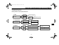
TABLE OF CONTENTS
LOCATION OF IMPORTANT
LABELS ............................................1-1
FOR YOUR SAFETY –
PRE-OPERATION CHECKS ............. 5-1
Pre-operation check list ................. 5-2
SAFETY INFORMATION ..................2-1
DESCRIPTION ..................................3-1
Left view ..........................................3-1
Right view ........................................3-2
Controls and instruments ................3-3
INSTRUMENT AND CONTROL
FUNCTIONS .......................................4-1
Handlebar switch ............................4-1
Clutch lever ....................................4-1
Shift pedal ......................................4-1
Brake lever .....................................4-2
Brake pedal ....................................4-2
Fuel tank cap ..................................4-3
Fuel ................................................4-3
Fuel tank breather hose .................4-5
Fuel cock ........................................4-5
Starter (choke) knob .......................4-6
Kickstarter ......................................4-6
Seat ................................................4-7
Adjusting the front fork ...................4-7
Front fork bleeding .........................4-9
Adjusting the shock absorber
assembly .....................................4-9
Removable sidestand ...................4-12
OPERATION AND IMPORTANT
RIDING POINTS ................................ 6-1
Starting and warming up a cold
engine ......................................... 6-1
Starting a warm engine .................. 6-1
Shifting ........................................... 6-2
Engine break-in .............................. 6-3
Parking ........................................... 6-4
PERIODIC MAINTENANCE AND
ADJUSTMENT................................... 7-1
Periodic maintenance and
lubrication chart .......................... 7-2
Checking the spark plug ................ 7-8
Transmission oil ............................. 7-9
Coolant ........................................ 7-10
Cleaning the air filter element ...... 7-12
Adjusting the carburetor ............... 7-14
Adjusting the engine idling
speed ........................................ 7-14
Adjusting the throttle cable free
play ........................................... 7-14
Tires ............................................. 7-15
Spoke wheels .............................. 7-17
Adjusting the clutch lever free
play ........................................... 7-17
Checking the front brake lever
free play .................................... 7-18
Checking the shift pedal ............... 7-18
Checking the front and rear brake
pads .......................................... 7-19
Checking the brake fluid level ...... 7-19
Changing the brake fluid .............. 7-20
Drive chain slack .......................... 7-21
Cleaning and lubricating the
drive chain ................................ 7-22
Checking and lubricating the
cables ....................................... 7-23
Checking and lubricating the
throttle grip and cable ............... 7-23
Checking and lubricating the
brake and clutch levers ............. 7-23
Checking and lubricating the
brake pedal ............................... 7-24
Lubricating the swingarm pivots ... 7-24
Lubricating the rear suspension ... 7-25
Checking the front fork ................. 7-25
Checking the steering .................. 7-26
Checking the wheel bearings ....... 7-26
Supporting the motorcycle ........... 7-26
Front wheel .................................. 7-27
Rear wheel ................................... 7-28
Troubleshooting ........................... 7-29
Troubleshooting charts ................. 7-31
U5PA17E0.book Page 2 Thursday, June 12, 2008 6:51 PM
TABLE OF CONTENTS
MOTORCYCLE CARE AND
STORAGE ..........................................8-1
Matte color caution .........................8-1
Care ................................................8-1
Storage ...........................................8-3
SPECIFICATIONS .............................9-1
CONSUMER INFORMATION...........10-1
Identification numbers ..................10-1
YAMAHA MOTOR
CORPORATION, U.S.A.
YZ/WR MOTORCYCLE
LIMITED WARRANTY ..............10-2
U5PA17E0.book Page 1 Thursday, June 12, 2008 6:51 PM
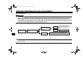
LOCATION OF IMPORTANT LABELS
EAU41371
Read and understand all of the labels on your vehicle. They contain important information for safe and proper operation of
your vehicle. Never remove any labels from your vehicle. If a label becomes difficult to read or comes off, a replacement label
is available from your Yamaha dealer.
1-1
1
U5PA17E0.book Page 2 Thursday, June 12, 2008 6:51 PM
LOCATION OF IMPORTANT LABELS
1
1
4
Use premium unleaded
gasoline/oil premix only.
WARNING
BEFORE YOU OPERATE THIS VEHICLE, READ
THE OWNER’S MANUAL AND ALL LABELS.
NEVER CARRY A PASSENGER. You increase
your risk of losing control if you carry a passenger.
NEVER OPERATE THIS VEHICLE ON PUBLIC
ROADS. You can collide with another vehicle if
you operate this vehicle on a public road.
ALWAYS WEAR AN APPROVED MOTORCYCLE
HELMET, eye protection, and protective clothing.
EXPERIENCED RIDER ONLY.
3XJ-2415E-A1.
2
5PA-2118K-00
3
5
WARNING
TIRE INFORMATION
Cold tire normal pressure should be set as
follows.
FRONT : 100kPa, {1.00kgf/cm2}, 15psi
REAR : 100kPa, {1.00kgf/cm2}, 15psi
Riding as a passenger can cause the vehicle
to go out of control.
Loss of control can cause a collision
or rollover, which can result in severe injury
or death.
3RV-21668-A0
NEVER ride as a passenger.
3XJ-2151H-A1
1-2
U5PA17E0.book Page 1 Thursday, June 12, 2008 6:51 PM
SAFETY INFORMATION
EAU41462
Be a Responsible Owner
As the vehicle’s owner, you are responsible for the safe and proper operation
of your motorcycle.
Motorcycles are single-track vehicles.
Their safe use and operation are dependent upon the use of proper riding
techniques as well as the expertise of
the operator. Every operator should
know the following requirements before
riding this motorcycle.
He or she should:
● Obtain thorough instructions from
a competent source on all aspects
of motorcycle operation.
● Observe the warnings and maintenance requirements in this Owner’s Manual.
● Obtain qualified training in safe
and proper riding techniques.
● Obtain professional technical service as indicated in this Owner’s
Manual and/or when made necessary by mechanical conditions.
Safe Riding
Perform the pre-operation checks each
time you use the vehicle to make sure it
is in safe operating condition. Failure to
inspect or maintain the vehicle properly
increases the possibility of an accident
or equipment damage. See page 5-1
for a list of pre-operation checks.
● This motorcycle is designed for offroad use only, therefore, it is illegal
to operate it on public streets,
roads, or highways, even a dirt or
gravel one. Off-road use on public
lands may be illegal. Please check
local regulations before riding.
● This motorcycle is designed to carry the operator only. No passengers.
● The failure of motorists to detect
and recognize motorcycles in traffic is the predominating cause of
automobile/motorcycle accidents.
Many accidents have been caused
by an automobile driver who did
not see the motorcycle. Making
2-1
●
yourself conspicuous appears to
be very effective in reducing the
chance of this type of accident.
Therefore:
• Wear a brightly colored jacket.
• Use extra caution when you are
approaching
and
passing
through intersections, since intersections are the most likely
places for motorcycle accidents
to occur.
• Ride where other motorists can
see you. Avoid riding in another
motorist’s blind spot.
Many accidents involve inexperienced operators.
• Make sure that you are qualified
and that you only lend your
motorcycle to other qualified operators.
• Know your skills and limits.
Staying within your limits may
help you to avoid an accident.
• We recommend that you practice riding your motorcycle until
you have become thoroughly familiar with the motorcycle and all
of its controls.
2
U5PA17E0.book Page 2 Thursday, June 12, 2008 6:51 PM
SAFETY INFORMATION
●
2
●
●
●
●
Many accidents have been caused
by error of the motorcycle operator. A typical error made by the operator is veering wide on a turn
due to excessive speed or undercornering (insufficient lean angle
for the speed). Never travel faster
than warranted by conditions.
Ride cautiously in unfamiliar areas. You may encounter hidden
obstacles that could cause an accident.
The posture of the operator is important for proper control. The operator should keep both hands on
the handlebar and both feet on the
operator footrests during operation
to maintain control of the motorcycle.
Never ride under the influence of
alcohol or other drugs.
Be sure the transmission is in neutral before starting the engine.
Protective apparel
The majority of fatalities from motorcycle accidents are the result of head
injuries. The use of a safety helmet is
the single most critical factor in the prevention or reduction of head injuries.
● Always wear an approved helmet.
● Wear a face shield or goggles.
Wind in your unprotected eyes
could contribute to an impairment
of vision that could delay seeing a
hazard.
● The use of a jacket, heavy boots,
trousers, gloves, etc., is effective in
preventing or reducing abrasions
or lacerations.
● Never wear loose-fitting clothes,
otherwise they could catch on the
control levers, footrests, or wheels
and cause injury or an accident.
● Always wear protective clothing
that covers your legs, ankles, and
feet. The engine or exhaust system become very hot during or after operation and can cause burns.
2-2
Avoid Carbon Monoxide Poisoning
All engine exhaust contains carbon
monoxide, a deadly gas. Breathing carbon monoxide can cause headaches,
dizziness, drowsiness, nausea, confusion, and eventually death.
Carbon Monoxide is a colorless, odorless, tasteless gas which may be
present even if you do not see or smell
any engine exhaust. Deadly levels of
carbon monoxide can collect rapidly
and you can quickly be overcome and
unable to save yourself. Also, deadly
levels of carbon monoxide can linger
for hours or days in enclosed or poorly
ventilated areas. If you experience any
symptoms of carbon monoxide poisoning, leave the area immediately, get
fresh air, and SEEK MEDICAL TREATMENT.
● Do not run engine indoors. Even if
you try to ventilate engine exhaust
with fans or open windows and
doors, carbon monoxide can rapidly reach dangerous levels.
● Do not run engine in poorly ventilated or partially enclosed areas
such as barns, garages, or carports.
U5PA17E0.book Page 3 Thursday, June 12, 2008 6:51 PM
SAFETY INFORMATION
●
Do not run engine outdoors where
engine exhaust can be drawn into
a building through openings such
as windows and doors.
Genuine Yamaha Accessories
Choosing accessories for your vehicle
is an important decision. Genuine
Yamaha accessories, which are available only from a Yamaha dealer, have
been designed, tested, and approved
by Yamaha for use on your vehicle.
Many companies with no connection to
Yamaha manufacture parts and accessories or offer other modifications for
Yamaha vehicles. Yamaha is not in a
position to test the products that these
aftermarket
companies
produce.
Therefore, Yamaha can neither endorse nor recommend the use of accessories not sold by Yamaha or
modifications not specifically recommended by Yamaha, even if sold and
installed by a Yamaha dealer.
Aftermarket Parts, Accessories, and
Modifications
While you may find aftermarket products similar in design and quality to
genuine Yamaha accessories, recognize that some aftermarket accessories
or modifications are not suitable because of potential safety hazards to you
or others. Installing aftermarket products or having other modifications performed to your vehicle that change any
of the vehicle’s design or operation
characteristics can put you and others
at greater risk of serious injury or death.
You are responsible for injuries related
to changes in the vehicle.
Keep the following guidelines in mind,
as well as those provided under “Loading” when mounting accessories.
● Never install accessories that
would impair the performance of
your motorcycle. Carefully inspect
the accessory before using it to
make sure that it does not in any
way reduce ground clearance or
●
2-3
cornering clearance, limit suspension travel, steering travel or control operation.
• Accessories fitted to the handlebar or the front fork area can
create instability due to improper
weight distribution. If accessories are added to the handlebar
or front fork area, they must be
as lightweight as possible and
should be kept to a minimum.
• Bulky or large accessories may
seriously affect the stability of
the motorcycle. Wind may attempt to lift the motorcycle, or
the motorcycle may become unstable in cross winds.
• Certain accessories can displace the operator from his or
her normal riding position. This
improper position limits the freedom of movement of the operator and may limit control ability,
therefore, such accessories are
not recommended.
Use caution when adding electrical accessories. If electrical accessories exceed the capacity of the
motorcycle’s electrical system, an
2
U5PA17E0.book Page 4 Thursday, June 12, 2008 6:51 PM
SAFETY INFORMATION
electric failure could result, which
could cause a dangerous loss of
lights or engine power.
2
Aftermarket Tires and Rims
The tires and rims that came with your
motorcycle were designed to match the
performance capabilities and to provide
the best combination of handling, braking, and comfort. Other tires, rims, sizes, and combinations may not be
appropriate. Refer to page 7-15 for tire
specifications and more information on
replacing your tires.
2-4
U5PA17E0.book Page 1 Thursday, June 12, 2008 6:51 PM
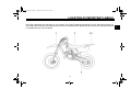
DESCRIPTION
EAU10410
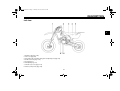
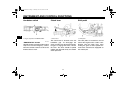
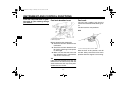
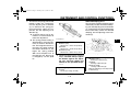
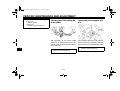
Left view
3
1.
2.
3.
4.
5.
6.
7.
8.
Radiator cap (page 7-10)
Fuel cock (page 4-5)
Shock absorber assembly spring preload adjusting nut (page 4-9)
Air filter element (page 7-12)
Seat (page 4-7)
Shift pedal (page 4-1)
Throttle stop screw (page 7-14)
Starter (choke) knob (page 4-6)
3-1
U5PA17E0.book Page 2 Thursday, June 12, 2008 6:51 PM
DESCRIPTION
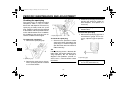
EAU10420
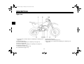
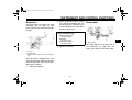
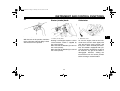
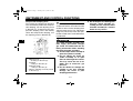
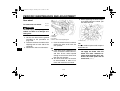
Right view
3
9. Brake pedal (page 4-2)
10.Transmission oil drain bolt (page 7-9)
11.Shock absorber assembly rebound damping force adjusting screw
(page 4-9)
1. Shock absorber assembly compression damping force adjusting screw
(page 4-9)
2. Kickstarter (page 4-6)
3. Front fork rebound damping force adjusting screw (page 4-7)
4. Bleed screw (page 4-9)
5. Front fork compression damping force adjusting screw (page 4-7)
6. Spark plug cap (page 7-8)
7. Transmission oil filler cap (page 7-9)
8. Coolant drain bolt (page 7-11)
3-2
U5PA17E0.book Page 3 Thursday, June 12, 2008 6:51 PM
DESCRIPTION
EAU10430
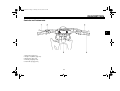
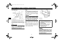
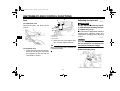
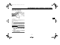
Controls and instruments
3
1.
2.
3.
4.
5.
Clutch lever (page 4-1)
Engine stop button (page 4-1)
Brake lever (page 4-2)
Throttle grip (page 7-14)
Fuel tank cap (page 4-3)
3-3
U5PA17E0.book Page 1 Thursday, June 12, 2008 6:51 PM
INSTRUMENT AND CONTROL FUNCTIONS
EAU40660
EAU12850
EAU12870
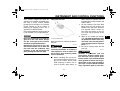
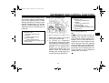
Handlebar switch
Clutch lever
Shift pedal
1. Engine stop button “ENGINE STOP”
1. Clutch lever
1. Shift pedal
The clutch lever is located at the left
handlebar grip. To disengage the
clutch, pull the lever toward the handlebar grip. To engage the clutch, release
the lever. The lever should be pulled
rapidly and released slowly for smooth
clutch operation.
The shift pedal is located on the left
side of the engine and is used in combination with the clutch lever when
shifting the gears of the 6-speed constant-mesh transmission equipped on
this motorcycle.
4
EAU12670
“ENGINE STOP” button
Hold this button pushed until the engine
stops in case of an emergency, such as
when the vehicle overturns or when the
throttle cable is stuck.
4-1
U5PA17E0.book Page 2 Thursday, June 12, 2008 6:51 PM
INSTRUMENT AND CONTROL FUNCTIONS
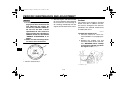
EAU41261
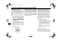
Brake lever
The brake lever is located at the right
handlebar grip. To apply the front
brake, pull the lever toward the handlebar grip.
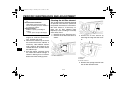
2. While holding the lever pushed
away from the handlebar grip, turn
the adjusting bolt in direction (a) to
increase the distance, and in direction (b) to decrease it.
Distance between the brake lever
and the handlebar grip:
Minimum (shortest):
76 mm (2.99 in)
Standard:
95 mm (3.74 in)
Maximum (longest):
97 mm (3.82 in)
3. Tighten the locknut.
1.
2.
3.
4.
Brake lever
Locknut
Adjusting bolt
Distance between brake lever and handlebar
grip
The brake lever is equipped with a position adjusting bolt. Adjust the distance
between the brake lever and the handlebar grip as follows.
1. Loosen the locknut.
4-2
EAU12941
Brake pedal
4
1. Brake pedal
The brake pedal is on the right side of
the motorcycle. To apply the rear
brake, press down on the brake pedal.
U5PA17E0.book Page 3 Thursday, June 12, 2008 6:51 PM
INSTRUMENT AND CONTROL FUNCTIONS
EAU13182
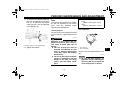
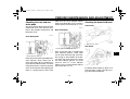
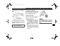
Fuel tank cap
EAU41833
Fuel
This motorcycle has been designed to
use a premixed fuel of gasoline and 2stroke engine oil. Always mix the gasoline and oil in a clean container before
filling the fuel tank.
ECA15601
NOTICE
Always use fresh gasoline, and fill
the fuel tank with a fresh mix just before riding. Do not use premixed fuel
that is more than a few hours old.
4
1. Fuel tank cap
To remove the fuel tank cap, turn it
counterclockwise, and then pull it off.
To install the fuel tank cap, insert it into
the tank opening, and then turn it clockwise.
EWA11091
WARNING
Make sure that the fuel tank cap is
properly closed after filling fuel.
Leaking fuel is a fire hazard.
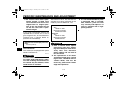
Mixing gasoline and 2-stroke engine
oil
Pour 2-stroke engine oil into a clean
container, and then add gasoline. To
mix the fuel thoroughly, shake the container from side to side.
1. 2-stroke engine oil
2. Gasoline
3. Container
Recommended fuel:
Premium unleaded gasoline only
Recommended 2-stroke engine oil:
See page 9-1.
Fuel tank capacity:
5.0 L (1.32 US gal, 1.10 Imp.gal)
Mixing ratios (gasoline to oil):
Break-in period: 15:1
After break-in: 30:1
ECA15590
NOTICE
Use only unleaded gasoline. The use
of leaded gasoline will cause severe
damage to internal engine parts,
such as the piston rings as well as to
the exhaust system.
4-3
U5PA17E0.book Page 4 Thursday, June 12, 2008 6:51 PM
INSTRUMENT AND CONTROL FUNCTIONS
Your Yamaha engine has been designed to use premium unleaded gasoline with a pump octane number
[(R+M)/2] of 91 or higher, or a research
octane number of 95 or higher. If
knocking (or pinging) occurs, use a
gasoline of a different brand.
If the recommended 2-stroke engine oil
is not available, use an equivalent oil.
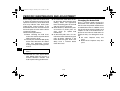
Filling the fuel tank
ECA15551
NOTICE
Never mix two brands of 2-stroke engine oil in the same batch. Always
use the same type of oil to ensure
maximum engine performance.
Should it be necessary to use a different oil brand, be sure to drain the
fuel tank and the carburetor float
chamber of the old premixed fuel
prior to filling with the new type.
1. Fuel level
2. Fuel tank filler tube
Make sure there is sufficient gasoline in
the tank.
EWA10881
WARNING
Gasoline and gasoline vapors are
extremely flammable. To avoid fires
and explosions and to reduce the
risk of injury when refueling, follow
these instructions.
1. Before refueling, turn off the engine and be sure that no one is sitting on the vehicle. Never refuel
while smoking, or while in the vicinity of sparks, open flames, or
4-4
other sources of ignition such as
the pilot lights of water heaters and
clothes dryers.
2. Do not overfill the fuel tank. Stop
filling when the fuel reaches the
bottom of the filler tube. Because
fuel expands when it heats up,
heat from the engine or the sun
can cause fuel to spill out of the
fuel tank.
3. Wipe up any spilled fuel immediately. NOTICE: Immediately wipe
off spilled fuel with a clean, dry,
soft cloth, since fuel may deteriorate painted surfaces or plastic
parts. [ECA10071]
4. Be sure to securely close the fuel
tank cap.
EWA15151
WARNING
Gasoline is poisonous and can
cause injury or death. Handle gasoline with care. Never siphon gasoline by mouth. If you should swallow
some gasoline or inhale a lot of gasoline vapor, or get some gasoline in
your eyes, see your doctor immediately. If gasoline spills on your skin,
4
U5PA17E0.book Page 5 Thursday, June 12, 2008 6:51 PM
INSTRUMENT AND CONTROL FUNCTIONS
wash with soap and water. If gasoline spills on your clothing, change
your clothes.
EAU41360
Fuel tank breather hose
EAU41280
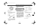
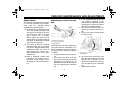
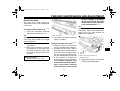
Fuel cock
The fuel cock supplies fuel from the
tank to the carburetor while filtering it also.
The fuel cock has two positions:
OFF
4
1. Fuel tank breather hose
2. One-way valve
Before operating the motorcycle:
● Check the fuel tank breather hose
connection.
● Check the fuel tank breather hose
for cracks or damage, and replace
it if damaged.
● Make sure that the end of the fuel
tank breather hose is not blocked,
and clean it if necessary.
TIP
If the fuel tank breather hose falls out,
reinstall it on the fuel tank cap with the
arrow mark on the one-way valve pointed downward as shown.
4-5
1. Arrow mark positioned over “OFF”
With the lever in this position, fuel will
not flow. Always return the lever to this
position when the engine is not running.
U5PA17E0.book Page 6 Thursday, June 12, 2008 6:51 PM
INSTRUMENT AND CONTROL FUNCTIONS
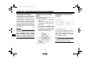
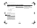
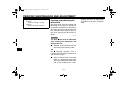
ON
EAU13640
EAU13650
Starter (choke) knob
Kickstarter
1. Starter (choke) knob
1. Kickstarter lever
Starting a cold engine requires a richer
air-fuel mixture, which is supplied by
the starter (choke).
Move the knob in direction (a) to turn on
the starter (choke).
Move the knob in direction (b) to turn off
the starter (choke).
To start the engine, fold out the kickstarter lever, move it down lightly with
your foot until the gears engage, and
then push it down smoothly but forcefully. This model is equipped with a primary kickstarter, allowing the engine to
be started in any gear if the clutch is
disengaged. However, shifting the
transmission into the neutral position
before starting is recommended.
4
1. Arrow mark positioned over “ON”
With the lever in this position, fuel flows
to the carburetor. Normal riding is done
with the lever in this position.
4-6
U5PA17E0.book Page 7 Thursday, June 12, 2008 6:51 PM
INSTRUMENT AND CONTROL FUNCTIONS
EAU46280
Seat
To remove the seat
Remove the bolts, and then pull the
seat off.
1
2
EWA10180
WARNING
Always adjust both fork legs equally, otherwise poor handling and loss
of stability may result.
2
3
This front fork is equipped with rebound
damping force adjusting screws and
compression damping force adjusting
screws.
1. Slot
2. Projection
3. Seat holder
4
EAU42051
Adjusting the front fork
ECA10101
NOTICE
2. Place the seat in the original position, and then tighten the bolts.
1. Bolt
To install the seat
1. Fit the slot in the seat onto the projection on the fuel tank, and insert
the projection on the seat into the
seat holder as shown.
TIP
Make sure that the seat is properly secured before riding.
To avoid damaging the mechanism,
do not attempt to turn beyond the
maximum or minimum settings.
Rebound damping force
1. Rebound damping force adjusting screw
4-7
U5PA17E0.book Page 8 Thursday, June 12, 2008 6:51 PM
INSTRUMENT AND CONTROL FUNCTIONS
To increase the rebound damping force
and thereby harden the rebound damping, turn the adjusting screw on each
fork leg in direction (a). To decrease the
rebound damping force and thereby
soften the rebound damping, turn the
adjusting screw on each fork leg in direction (b).
Rebound damping setting:
Minimum (soft):
20 click(s) in direction (b)*
Standard:
7 click(s) in direction (b)*
Maximum (hard):
1 click(s) in direction (b)*
* With the adjusting screw fully turned
in direction (a)
Compression damping force
Compression damping setting:
Minimum (soft):
20 click(s) in direction (b)*
Standard:
10 click(s) in direction (b)*
Maximum (hard):
1 click(s) in direction (b)*
* With the adjusting screw fully turned
in direction (a)
3. Install the rubber cap.
1. Rubber cap
2. Compression damping force adjusting screw
1. Remove the rubber cap by pulling
it out of the front fork leg.
2. To increase the compression
damping force and thereby harden
the compression damping, turn the
adjusting screw on each fork leg in
direction (a). To decrease the
compression damping force and
thereby soften the compression
damping, turn the adjusting screw
on each fork leg in direction (b).
4-8
TIP
Although the total number of clicks of a
damping force adjusting mechanism
may not exactly match the above specifications due to small differences in
production, the actual number of clicks
always represents the entire adjusting
range. To obtain a precise adjustment,
it would be advisable to check the number of clicks of each damping force adjusting mechanism and to modify the
specifications as necessary.
4
U5PA17E0.book Page 9 Thursday, June 12, 2008 6:51 PM
INSTRUMENT AND CONTROL FUNCTIONS
EAU14791
EAU42062
TIP
When bleeding the front fork, there
should be no weight on the front end of
the vehicle.
Front fork bleeding
2. Remove the bleed screws and allow all of the air to escape from
each fork leg.
3. Install the bleed screws.
Adjusting the shock absorber
assembly
This shock absorber assembly is
equipped with a spring preload adjusting nut, a rebound damping force adjusting screw and a compression
damping force adjusting screw.
ECA10101
NOTICE
To avoid damaging the mechanism,
do not attempt to turn beyond the
maximum or minimum settings.
4
1. Bleed screw
EWA10200
WARNING
Spring preload
Adjust the spring preload as follows.
1. Loosen the locknut.
Always bleed both fork legs, otherwise poor handling and loss of stability may result.
When riding in extremely rough conditions, the air temperature and pressure
in the front fork will rise. This will increase the spring preload and harden
the front suspension. If this occurs,
bleed the front fork as follows.
1. Elevate the front wheel by placing
a suitable stand under the engine.
1. Locknut
2. Spring preload adjusting nut
4-9
U5PA17E0.book Page 10 Thursday, June 12, 2008 6:51 PM
INSTRUMENT AND CONTROL FUNCTIONS
2. To increase the spring preload and
thereby harden the suspension,
turn the adjusting nut in direction
(a). To decrease the spring preload and thereby soften the suspension, turn the adjusting nut in
direction (b).
● A special wrench can be obtained at a Yamaha dealer to
make this adjustment.
● The spring preload setting is
determined by measuring distance A, shown in the illustration. The longer distance A is,
the lower the spring preload;
the shorter distance A is, the
higher the spring preload.
With each complete turn of
the adjusting nut, distance A
is changed by 1.5 mm (0.06
in).
Rebound damping force
To increase the rebound damping force
and thereby harden the rebound damping, turn the adjusting screw in direction
(a). To decrease the rebound damping
force and thereby soften the rebound
damping, turn the adjusting screw in direction (b).
1. Distance A
4
Spring preload:
Minimum (soft):
Distance A = 218.5 mm (8.60 in)
Standard:
Distance A = 215.0 mm (8.46 in)
Maximum (hard):
Distance A = 202.5 mm (7.97 in)
3. Tighten the locknut to the specified
torque. NOTICE: Always tighten
the locknut against the adjusting nut, and then tighten the
locknut to the specified torque.
[ECA10121]
Tightening torque:
Locknut:
35 Nm (3.5 m·kgf, 25 ft·lbf)
4-10
1. Rebound damping force adjusting screw
Rebound damping setting:
Minimum (soft):
20 click(s) in direction (b)*
Standard:
6 click(s) in direction (b)*
Maximum (hard):
1 click(s) in direction (b)*
* With the adjusting screw fully turned
in direction (a)
U5PA17E0.book Page 11 Thursday, June 12, 2008 6:51 PM
INSTRUMENT AND CONTROL FUNCTIONS
Compression damping force
To increase the compression damping
force and thereby harden the compression damping, turn the adjusting screw
in direction (a). To decrease the compression damping force and thereby
soften the compression damping, turn
the adjusting screw in direction (b).
TIP
To obtain a precise adjustment, it is advisable to check the actual total number
of clicks or turns of each damping force
adjusting mechanism. This adjustment
range may not exactly match the specifications listed due to small differences
in production.
EWA10221
WARNING
4
1. Compression damping force adjusting screw
Compression damping setting:
Minimum (soft):
20 click(s) in direction (b)*
Standard:
9 click(s) in direction (b)*
Maximum (hard):
1 click(s) in direction (b)*
* With the adjusting screw fully turned
in direction (a)
This shock absorber assembly contains highly pressurized nitrogen
gas. Read and understand the following information before handling
the shock absorber assembly.
● Do not tamper with or attempt to
open the cylinder assembly.
● Do not subject the shock absorber assembly to an open
flame or other high heat source.
This may cause the unit to explode due to excessive gas
pressure.
● Do not deform or damage the
cylinder in any way. Cylinder
damage will result in poor
damping performance.
4-11
●
Do not dispose of a damaged or
worn-out shock absorber assembly yourself. Take the shock
absorber assembly to a Yamaha
dealer for any service.
U5PA17E0.book Page 12 Thursday, June 12, 2008 6:51 PM
INSTRUMENT AND CONTROL FUNCTIONS
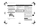
EAU41381
Removable sidestand
4
1. Sidestand
This motorcycle is equipped with a removable sidestand.
TIP
Make sure that the sidestand is properly secured when the motorcycle is being supported or is being transported.
EWA14601
WARNING
●
●
Never apply force on the motorcycle while it is on the sidestand.
Always remove the sidestand
before starting out.
4-12
U5PA17E0.book Page 1 Thursday, June 12, 2008 6:51 PM
FOR YOUR SAFETY – PRE-OPERATION CHECKS
EAU15595
Inspect your vehicle each time you use it to make sure the vehicle is in safe operating condition. Always follow the inspection
and maintenance procedures and schedules described in the Owner’s Manual.
EWA11151
WARNING
Failure to inspect or maintain the vehicle properly increases the possibility of an accident or equipment damage.
Do not operate the vehicle if you find any problem. If a problem cannot be corrected by the procedures provided in
this manual, have the vehicle inspected by a Yamaha dealer.
Before using this vehicle, check the following points:
5
5-1
U5PA17E0.book Page 2 Thursday, June 12, 2008 6:51 PM
FOR YOUR SAFETY – PRE-OPERATION CHECKS
EAU15605
Pre-operation check list
ITEM
CHECKS
PAGE
Fuel
• Check fuel level in fuel tank.
• Always use a fresh mixture of gasoline and oil.
• Check fuel line for leakage.
4-3
Transmission oil
• Check oil level in transmission case.
• If necessary, add recommended oil to specified level.
7-9
Coolant
• Check coolant level.
• If necessary, add recommended coolant to specified level.
• Check cooling system for leakage.
7-10
Front brake
•
•
•
•
•
•
•
Check operation.
If soft or spongy, have Yamaha dealer bleed hydraulic system.
Check brake pads for wear.
Replace if necessary.
Check fluid level in reservoir.
If necessary, add recommended brake fluid to specified level.
Check hydraulic system for leakage.
7-19, 7-19
Rear brake
•
•
•
•
•
•
•
Check operation.
If soft or spongy, have Yamaha dealer bleed hydraulic system.
Check brake pads for wear.
Replace if necessary.
Check fluid level in reservoir.
If necessary, add recommended brake fluid to specified level.
Check hydraulic system for leakage.
7-19, 7-19
Clutch
•
•
•
•
Check operation.
Lubricate cable if necessary.
Check lever free play.
Adjust if necessary.
Throttle grip
• Make sure that operation is smooth.
• Check cable free play.
• If necessary, have Yamaha dealer adjust cable free play and lubricate cable and
grip housing.
7-17
5-2
7-14, 7-23
5
U5PA17E0.book Page 3 Thursday, June 12, 2008 6:51 PM
FOR YOUR SAFETY – PRE-OPERATION CHECKS
ITEM
5
CHECKS
PAGE
Drive chain
•
•
•
•
Check chain slack.
Adjust if necessary.
Check chain condition.
Lubricate if necessary.
7-21, 7-22
Wheels and tires
•
•
•
•
•
Check for damage.
Check tire condition and tread depth.
Check air pressure.
Correct if necessary.
Check for loose spokes and tighten if necessary.
7-15, 7-17
Shift pedal
• Make sure that operation is smooth.
• Correct if necessary.
7-18
Brake pedal
• Make sure that operation is smooth.
• Lubricate pedal pivoting point if necessary.
7-24
Steering
• Check that the handlebar can be turned smoothly and has no excessive play.
7-26
Front fork and rear shock absorber assembly
• Check that they operate smoothly and there is no oil leakage.
Chassis fasteners
• Make sure that all nuts, bolts and screws are properly tightened.
• Tighten if necessary.
Moving parts and cables
• Check that the control cables move smoothly.
• Check that the control cables are not caught when the handlebars are turned or
when the front forks travel up and down.
• Lubricate moving parts and cables if necessary.
Exhaust system
• Check that the exhaust pipe is tightly mounted and has no cracks.
• Check for leakage.
—
Ignition system
• Check that all leads and cables are properly connected.
7-8
5-3
4-7, 4-9, 4-9, 7-25
—
7-23, 7-23, 7-24, 7-25
U5PA17E0.book Page 1 Thursday, June 12, 2008 6:51 PM
OPERATION AND IMPORTANT RIDING POINTS
EAU15951
Read the Owner’s Manual carefully to
become familiar with all controls. If
there is a control or function you do not
understand, ask your Yamaha dealer.
EWA10271
WARNING
Failure to familiarize yourself with
the controls can lead to loss of control, which could cause an accident
or injury.
EAU41304
Starting and warming up a
cold engine
1. Turn the fuel cock lever to “ON”.
2. Shift the transmission into the neutral position.
3. Turn the starter (choke) on and
completely close the throttle. (See
page 4-6.)
4. Start the engine by pushing the
kickstarter lever down. NOTICE:
For maximum engine life, always warm the engine up before
starting off. Never accelerate
hard when the engine is cold!
EAU16660
Starting a warm engine
Follow the same procedure as for starting a cold engine with the exception
that the starter (choke) is not required
when the engine is warm. Instead, start
the engine with the throttle slightly
open.
TIP
If the engine does not start after several
kicks, try again with the throttle 1/4 to
1/2 open.
6
[ECA11131]
5. When the engine is warm, turn the
starter (choke) off.
TIP
The engine is warm when it responds
normally to the throttle with the starter
(choke) turned off.
6-1
U5PA17E0.book Page 2 Thursday, June 12, 2008 6:51 PM
OPERATION AND IMPORTANT RIDING POINTS
EAU16671
Shifting
ECA10260
NOTICE
●
1. Shift pedal
2. Neutral position
6
Shifting gears lets you control the
amount of engine power available for
starting off, accelerating, climbing hills,
etc.
The gear positions are shown in the illustration.
●
Even with the transmission in
the neutral position, do not
coast for long periods of time
with the engine off, and do not
tow the motorcycle for long distances. The transmission is
properly lubricated only when
the engine is running. Inadequate lubrication may damage
the transmission.
Always use the clutch while
changing gears to avoid damaging the engine, transmission,
and drive train, which are not
designed to withstand the
shock of forced shifting.
EAU16690
TIP
To shift the transmission into the neutral position, press the shift pedal down
repeatedly until it reaches the end of its
travel, and then slightly raise it.
To start out and accelerate
1. Pull the clutch lever to disengage
the clutch.
2. Shift the transmission into first
gear.
3. Open the throttle gradually and simultaneously release the clutch lever slowly.
6-2
4. Once the motorcycle has reached
a speed high enough to change
gears, close the throttle, and at the
same time, quickly pull the clutch
lever in.
5. Shift the transmission into second
gear. (Make sure not to shift the
transmission into the neutral position.)
6. Open the throttle halfway and
gradually release the clutch lever.
7. Follow the same procedure when
shifting to the next gear.
EAU16710
To decelerate
1. Close the throttle and apply both
the front and the rear brakes to
slow the motorcycle.
2. Downshift through the gears and
shift the transmission into the neutral position when the motorcycle
is almost completely stopped.
U5PA17E0.book Page 3 Thursday, June 12, 2008 6:51 PM
OPERATION AND IMPORTANT RIDING POINTS
EAU41503
Engine break-in
EWA10321
WARNING
Failure to properly maintain the vehicle or performing maintenance activities incorrectly may increase
your risk of injury or death during
service or while using the vehicle. If
you are not familiar with vehicle service, have a Yamaha dealer perform
service.
4.
5.
1. Before starting the engine, fill the
fuel tank with a break-in oil-fuel
mixture as follows.
Recommended 2-stroke engine oil:
See page 9-1.
Mixing ratio (gasoline to oil):
15:1
2. Start and warm up the engine.
Check the operation of the controls
and the engine stop button. (See
page 4-1.)
3. Operate the motorcycle in the lower gears at moderate throttle openings for five to eight minutes. Stop
the engine and check the spark
6.
7.
plug condition (see page 7-8); it
will show a rich condition during
break-in.
Allow the engine to cool. Restart
the engine and operate the motorcycle as in the step above for five
minutes. Then, very briefly shift to
the higher gears and check the
full-throttle response. Stop the engine and check the spark plug.
After again allowing the engine to
cool, restart and run the motorcycle for five more minutes. Full
throttle and the higher gears may
be used, but sustained full-throttle
operation should be avoided. Stop
the engine and check the spark
plug again.
Allow the engine to cool, remove
the cylinder head and cylinder, and
inspect the piston and cylinder.
Remove any high spots on the piston with #600-grit wet sandpaper.
Clean all components and carefully reassemble the cylinder head
and cylinder.
Drain the break-in oil-fuel mixture
from the fuel tank and refill with the
specified mix. (See page 4-3.)
6-3
8. Start the engine and check the operation of the motorcycle throughout its entire operating range. Stop
the engine and check the spark
plug condition. Restart the motorcycle and ride it for about 10 to 15
more minutes. The motorcycle will
now be ready to ride normally.
After the engine break-in period, thoroughly check the motorcycle for loose
parts, oil leakage and any other problems. Be sure to inspect and make adjustments thoroughly, especially cable
and drive chain slack and loose
spokes. In addition, check all fittings
and fasteners for looseness, and tighten if necessary.
ECA15560
NOTICE
●
When any of the following parts
have been replaced, they must
be broken in.
Cylinder or crankshaft:
About one hour of break-in operation is necessary.
Piston, rings or transmission
gears:
6
U5PA17E0.book Page 4 Thursday, June 12, 2008 6:51 PM
OPERATION AND IMPORTANT RIDING POINTS
●
These parts require about 30
minutes of break-in operation at
half-throttle or less. Observe the
condition of the engine carefully
during operation.
If any engine trouble should occur during the engine break-in
period, immediately have a
Yamaha dealer check the vehicle.
EAU17191
Parking
When parking, stop the engine, and
then turn the fuel cock lever to “OFF”.
EWA10311
WARNING
●
●
6
●
Since the engine and exhaust
system can become very hot,
park in a place where pedestrians or children are not likely to
touch them and be burned.
Do not park on a slope or on soft
ground, otherwise the vehicle
may overturn, increasing the
risk of a fuel leak and fire.
Do not park near grass or other
flammable materials which
might catch fire.
6-4
U5PA17E0.book Page 1 Thursday, June 12, 2008 6:51 PM
PERIODIC MAINTENANCE AND ADJUSTMENT
EAU42071
EWA15121
WARNING
Periodic inspection, adjustment, and lubrication will keep your vehicle in the
safest and most efficient condition possible. Safety is an obligation of the vehicle owner/operator. The most important
points of vehicle inspection, adjustment, and lubrication are explained on
the following pages.
The intervals given in the periodic
maintenance and lubrication chart
should be simply considered as a general guide under normal riding conditions. However, depending on the
weather, terrain, geographical location,
and individual use, the maintenance intervals may need to be shortened.
Turn off the engine when performing
maintenance
unless
otherwise
specified.
● A running engine has moving
parts that can catch on body
parts or clothing and electrical
parts that can cause shocks or
fires.
● Running the engine while servicing can lead to eye injury,
burns, fire, or carbon monoxide
poisoning – possibly leading to
death. See page 2-1 for more information about carbon monoxide.
7
EWA10321
WARNING
Failure to properly maintain the vehicle or performing maintenance activities incorrectly may increase
your risk of injury or death during
service or while using the vehicle. If
you are not familiar with vehicle service, have a Yamaha dealer perform
service.
7-1
U5PA17E0.book Page 2 Thursday, June 12, 2008 6:51 PM
PERIODIC MAINTENANCE AND ADJUSTMENT
EAU41796
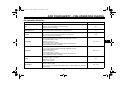
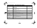
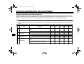
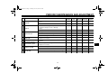
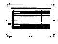
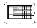
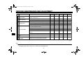
Periodic maintenance and lubrication chart
The following chart is intended as a general guide to maintenance and lubrication. Bear in mind that such factors as weather,
terrain, geographical location, and individual usage will alter the required maintenance and lubrication intervals. If you are in
doubt as to what intervals to follow in maintaining and lubricating your motorcycle, consult your Yamaha dealer.
TIP
●
●
From the seventh race, repeat the maintenance intervals starting from “Every race”.
Items marked with an asterisk should be performed by a Yamaha dealer as they require special tools, data and technical
skills.
NO.
ROUTINE
After
break-in
Every
race
• Check piston for carbon deposits and cracks or damage.
• Clean.
√
√
√
√
ITEM
1 * Piston
Every
Every
third race fifth race
√
• Replace.
7
2 * Piston rings
3 *
Piston pin and small
end bearing
4 * Cylinder head
• Check piston ring end gap and rings for damage.
√
• Replace.
As
required
√
√
√
• Check piston pin and small end bearing for damage.
√
• Replace.
• Check cylinder head for carbon deposits.
• Clean.
√
√
• Check cylinder head gasket for damage.
• Tighten cylinder head nuts if necessary.
√
√
√
• Replace cylinder head gasket.
7-2
U5PA17E0.book Page 3 Thursday, June 12, 2008 6:51 PM
PERIODIC MAINTENANCE AND ADJUSTMENT
NO.
ITEM
5 * Cylinder
After
break-in
ROUTINE
• Check cylinder for score marks or wear.
• Clean.
√
Every
race
Every
Every
third race fifth race
√
√
• Replace.
6 * Clutch
• Check clutch housing, friction plates, clutch plates
and clutch springs for wear or damage.
• Adjust.
√
√
√
• Replace.
√
• Change the transmission oil.
7 * Transmission
• Check transmission for damage.
√
√
√
Shift forks, guide bars,
shift cam
• Check all parts for wear and damage.
• Replace if necessary.
9 *
Rotor nut
(flywheel magneto)
• Tighten.
11 * Exhaust system
12 * Crankshaft
√
• Replace bearings.
8 *
10 * Kickstarter system
As
required
√
√
• Check idle gear for damage.
• Replace if necessary.
√
• Check exhaust pipe and muffler for carbon deposits.
√
√
• Clean.
√
• Check crankshaft for carbon deposits and damage.
√
√
• Clean.
√
√
7-3
7
U5PA17E0.book Page 4 Thursday, June 12, 2008 6:51 PM
PERIODIC MAINTENANCE AND ADJUSTMENT
NO.
ITEM
13 * Carburetor
14
Spark plug
ROUTINE
After
break-in
Every
race
• Check carburetor settings and for obstructions.
√
√
• Adjust and clean.
√
√
• Check condition.
• Clean and regap.
√
√
Every
Every
third race fifth race
√
• Replace.
15 * Drive chain
• Check chain slack, alignment and condition.
• Adjust and thoroughly lubricate chain with Yamaha
chain and cable lube or equivalent.
√
√
√
• Replace.
√
• Check coolant level and for leakage.
16 * Cooling system
17 * Chassis fasteners
√
√
• Check hoses for cracks or damage.
√
• Check radiator cap spring operation.
• Change coolant.
7
As
required
Every 2 years
• Check all chassis fitting and fasteners.
• Correct or tighten if necessary.
√
√
• Clean.
√
√
18 * Air filter element
√
√
• Replace.
19 * Frame
• Clean and check for damage.
√
20 * Fuel line
• Clean and check for leakage.
√
7-4
√
√
U5PA17E0.book Page 5 Thursday, June 12, 2008 6:51 PM
PERIODIC MAINTENANCE AND ADJUSTMENT
NO.
ROUTINE
After
break-in
Every
race
Adjust lever position and pedal height.
Lubricate pivot points.
Check brake disk surface.
Check fluid level and for leakage.
Tighten brake disk bolts, caliper bolts, master cylinder
bolts and union bolts.
√
√
ITEM
21 * Brakes
•
•
•
•
•
Every
Every
third race fifth race
√
• Replace brake pads.
• Replace brake fluid.
22 * Front fork
As
required
√
Every year
• Check operation and for oil leakage.
• Adjust if necessary.
• Clean dust seal and lubricate with lithium-soap-based
grease.
√
• Replace fork oil.
√
√
√
√
• Replace oil seals.
• Check operation and adjust.
√
• Tighten if necessary.
Shock absorber assem23 *
bly
• Lubricate with lithium-soap-based grease.
7-5
√
7
√
√
(After
washing
the
motorcycle
or riding in
the rain)
U5PA17E0.book Page 6 Thursday, June 12, 2008 6:51 PM
PERIODIC MAINTENANCE AND ADJUSTMENT
NO.
ITEM
24 *
Drive chain roller and
support guide
25 * Rear suspension
26 * Steering head
After
break-in
ROUTINE
Every
race
Every
Every
third race fifth race
• Check for wear or damage.
• Replace if necessary.
√
• Check operation and tighten if necessary.
√
√
• Lubricate with lithium-soap-based grease.
√
√
• Check operation, free play, and tighten if necessary.
√
√
√
• Clean and lubricate with lithium-soap-based grease.
√
• Replace bearings.
27 * Tires and wheels
• Check tire air pressure, wheel runout, spokes for
looseness, and tires for wear.
√
√
• Tighten sprocket bolts if necessary.
√
√
• Check wheel bearings for looseness.
√
• Lubricate wheel bearings with lithium-soap-based
grease.
√
√
• Replace wheel bearings.
7
Moving parts and ca28 *
bles
29 *
Throttle grip housing
and cable
As
required
• Lubricate.
√
√
• Check operation and free play.
• Adjust the throttle cable free play if necessary.
• Lubricate the throttle grip housing and cable.
√
√
EAU42011
TIP
●
Hydraulic brake service
• Regularly check and, if necessary, correct the brake fluid levels.
7-6
U5PA17E0.book Page 7 Thursday, June 12, 2008 6:51 PM
PERIODIC MAINTENANCE AND ADJUSTMENT
• Every two years replace the internal components of the brake master cylinders and calipers, and change the brake
fluid.
• Replace the brake hoses every four years and if cracked or damaged.
7
7-7
U5PA17E0.book Page 8 Thursday, June 12, 2008 6:51 PM
PERIODIC MAINTENANCE AND ADJUSTMENT
2. Check the spark plug for electrode
erosion and excessive carbon or
other deposits, and replace it if
necessary.
EAU19612
Checking the spark plug
The spark plug is an important engine
component, which is easy to check.
Since heat and deposits will cause any
spark plug to slowly erode, the spark
plug should be removed and checked
in accordance with the periodic maintenance and lubrication chart. In addition,
the condition of the spark plug can reveal the condition of the engine.
To remove the spark plug
1. Remove the spark plug cap.
7
1. Spark plug cap
2. Remove the spark plug as shown,
with a spark plug wrench available
at a Yamaha dealer.
Specified spark plug:
NGK/BR10EG
1. Spark plug wrench
To check the spark plug
1. Check that the porcelain insulator
around the center electrode of the
spark plug is a medium-to-light tan
(the ideal color when the vehicle is
ridden normally).
TIP
If the spark plug shows a distinctly different color, the engine could be operating improperly. Do not attempt to
diagnose such problems yourself. Instead, have a Yamaha dealer check
the vehicle.
7-8
To install the spark plug
1. Measure the spark plug gap with a
wire thickness gauge and, if necessary, adjust the gap to specification.
1. Spark plug gap
Spark plug gap:
0.5–0.6 mm (0.020–0.024 in)
U5PA17E0.book Page 9 Thursday, June 12, 2008 6:51 PM
PERIODIC MAINTENANCE AND ADJUSTMENT
2. Clean the surface of the spark plug
gasket and its mating surface, and
then wipe off any grime from the
spark plug threads.
3. Install the spark plug with the
spark plug wrench, and then tighten it to the specified torque.
Tightening torque:
Spark plug:
20 Nm (2.0 m·kgf, 14 ft·lbf)
TIP
If a torque wrench is not available when
installing a spark plug, a good estimate
of the correct torque is 1/4–1/2 turn
past finger tight. However, the spark
plug should be tightened to the specified torque as soon as possible.
4. Install the spark plug cap.
EAU41443
Transmission oil
The transmission oil must be checked
for oil leakage before each ride. If any
leakage is found, have a Yamaha dealer check and repair the motorcycle. In
addition, the transmission oil must be
changed at the intervals specified in the
periodic maintenance and lubrication
chart.
1. Start the engine, warm it up for
several minutes, and then turn it
off.
2. Place the motorcycle on a level
surface and hold it in an upright position.
3. Place an oil pan under the transmission to collect the used oil.
4. Remove the oil filler cap and drain
bolt to drain the oil from the transmission.
1. Transmission oil filler cap
2. Transmission oil drain bolt
5. Install the transmission oil drain
bolt, and then tighten it to the specified torque.
Tightening torque:
Transmission oil drain bolt:
10 Nm (1.0 m·kgf, 7.2 ft·lbf)
6. Refill with the specified amount of
the recommended transmission
oil, and then install and tighten the
oil filler cap.
Recommended transmission oil:
See page 9-1.
Oil change quantity:
0.50 L (0.53 US qt, 0.44 Imp.qt)
7-9
7
U5PA17E0.book Page 10 Thursday, June 12, 2008 6:51 PM
PERIODIC MAINTENANCE AND ADJUSTMENT
ECA10452
NOTICE
●
●
In order to prevent clutch slippage (since the transmission oil
also lubricates the clutch), do
not mix any chemical additives.
Do not use oils with a diesel
specification of “CD” or oils of a
higher quality than specified. In
addition, do not use oils labeled
“ENERGY CONSERVING II” or
higher.
Make sure that no foreign material enters the transmission.
7. Start the engine, and then let it idle
for several minutes while checking
the transmission for oil leakage. If
oil is leaking, immediately turn the
engine off and check for the cause.
EAU20070
Coolant
The coolant level should be checked
before each ride. In addition, the coolant must be changed at the intervals
specified in the periodic maintenance
and lubrication chart.
EAUM1293
To check the coolant level
1. Place the vehicle on a level surface and hold it in an upright position.
2. Remove the radiator cap and
check the coolant level in the radiator. WARNING! Never attempt
to remove the radiator cap when
the engine is hot. [EWA10381]
1
7
2
1. “CD” specification
2. “ENERGY CONSERVING II”
1. Radiator cap
7-10
U5PA17E0.book Page 11 Thursday, June 12, 2008 6:51 PM
PERIODIC MAINTENANCE AND ADJUSTMENT
EAUM1313
TIP
●
●
The coolant level must be checked
on a cold engine since the level
varies with engine temperature.
Make sure that the vehicle is positioned straight up when checking
the coolant level. A slight tilt to the
side can result in a false reading.
TIP
The coolant should be at the bottom of
the radiator filler neck. The level will
change with variation of engine temperature.
To change the coolant
1. Place the vehicle on a level surface and let the engine cool if necessary.
2. Place a container under the engine
to collect the used coolant.
3. Remove the coolant drain bolt and
then the radiator cap to drain the
cooling system. WARNING! Never attempt to remove the radiator cap when the engine is hot.
[EWA10381]
1. Radiator cap
4. After the coolant is completely
drained, thoroughly flush the cooling system with clean tap water.
5. Install the coolant drain bolt, and
then tighten it to the specified
torque.
TIP
Check the washer for damage and replace it if necessary.
Tightening torque:
Coolant drain bolt:
10 Nm (1.0 m·kgf, 7.2 ft·lbf)
1. Coolant drain bolt
1. Correct coolant level
6. Pour the recommended coolant
into the radiator until it is full.
3. If the coolant is below this level,
add coolant, and then install the
radiator cap.
7-11
7
U5PA17E0.book Page 12 Thursday, June 12, 2008 6:51 PM
PERIODIC MAINTENANCE AND ADJUSTMENT
EAU41433
Antifreeze/water mixture ratio:
1:1
Recommended antifreeze:
High-quality ethylene glycol antifreeze containing corrosion inhibitors
for aluminum engines
Coolant quantity:
Radiator capacity (including all
routes):
0.54 L (0.57 US qt, 0.48 Imp.qt)
7
7. Install the radiator cap, start the
engine, let it idle for several minutes, and then turn it off.
8. Remove the radiator cap to check
the coolant level in the radiator. If
necessary, add sufficient coolant
until it reaches the bottom of the
radiator filler neck, and then install
the radiator cap.
9. Start the engine, and then check
the vehicle for coolant leakage. If
coolant is leaking, have a Yamaha
dealer check the cooling system.
Cleaning the air filter element
The air filter element should be cleaned
or replaced at the intervals specified in
the periodic maintenance and lubrication chart. Clean or, if necessary, replace the air filter element more
frequently if you are riding in unusually
wet or dusty areas.
1. Remove the seat. (See page 4-7.)
2. Remove the air filter case cover as
shown.
3. Remove the air filter element by
removing the wing bolt and washer.
1. Air filter case cover
1. Wing bolt
2. Washer
3. Air filter element
4. Remove the sponge material from
the air filter element frame.
7-12
U5PA17E0.book Page 13 Thursday, June 12, 2008 6:51 PM
PERIODIC MAINTENANCE AND ADJUSTMENT
TIP
The sponge material should be wet but
not dripping.
Recommended oil:
Yamaha foam air filter oil or other
quality foam air filter oil
1. Sponge material
2. Air filter element frame
5. Clean the sponge material with
solvent, and then squeeze the remaining solvent out.
7. Pull the sponge material over the
air filter element frame.
8. Insert the air filter element into the
air filter case with the projection
facing upward, and then install the
washer and wing bolt. NOTICE:
Make sure that the air filter element is properly seated in the
air filter case. The engine
should never be operated without the air filter element installed, otherwise the piston(s)
and/or cylinder(s) may become
excessively worn. [ECA10481]
1. Air filter element
2. Projection
9. Install the air filter case cover in the
original position as shown.
7
10. Install the seat.
6. Apply oil of the recommended type
to the entire surface of the sponge
material, and then squeeze the excess oil out.
7-13
U5PA17E0.book Page 14 Thursday, June 12, 2008 6:51 PM
PERIODIC MAINTENANCE AND ADJUSTMENT
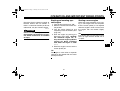
EAU42110
Adjusting the carburetor
The carburetor is an important part of
the engine and requires very sophisticated adjustment. Therefore, most carburetor adjustments should be left to a
Yamaha dealer, who has the necessary professional knowledge and experience. The adjustment described in the
following section, however, may be serviced by the owner as part of routine
maintenance.
ECA10550
NOTICE
7
The carburetor has been set and extensively tested at the Yamaha factory. Changing these settings
without sufficient technical knowledge may result in poor performance of or damage to the engine.
EAU44390
Adjusting the engine idling
speed
The engine idling speed must be adjusted when necessary.
1. Start the engine and thoroughly
warm it up.
2. Turn the throttle stop screw until
the engine runs at the lowest possible speed.
3. To increase the engine idling
speed, turn the throttle stop screw
in direction (a). To decrease the
engine idling speed, turn the throttle stop screw in direction (b).
EAU21370
Adjusting the throttle cable
free play
1. Throttle cable free play
The throttle cable free play should measure 3.0–5.0 mm (0.12–0.20 in) at the
throttle grip. Periodically check the
throttle cable free play and, if necessary, adjust it as follows.
TIP
The engine idling speed must be correctly adjusted before checking and adjusting the throttle cable free play.
1. Throttle stop screw
7-14
1. Loosen the locknut.
U5PA17E0.book Page 15 Thursday, June 12, 2008 6:51 PM
PERIODIC MAINTENANCE AND ADJUSTMENT
2. To increase the throttle cable free
play, turn the adjusting nut in direction (a). To decrease the throttle
cable free play, turn the adjusting
nut in direction (b).
EAU41821
Tires
To maximize the performance, durability, and safe operation of your motorcycle, note the following points
regarding the specified tires.
Tire air pressure
The tire air pressure should be checked
and, if necessary, adjusted before each
ride.
Standard tire air pressure:
Front:
100 kPa (1.00 kgf/cm², 15 psi)
Rear:
100 kPa (1.00 kgf/cm², 15 psi)
Tire inspection
2
EWA14381
WARNING
1. Locknut
2. Throttle cable free play adjusting nut
3. Tighten the locknut.
Operation of this vehicle with improper tire pressure may cause severe injury or death from loss of
control.
● The tire air pressure must be
checked and adjusted on cold
tires (i.e., when the temperature
of the tires equals the ambient
temperature).
● The tire air pressure must be adjusted in accordance with the
weight of the rider, the riding
speed, and the riding conditions.
7-15
1
1. Tire sidewall
2. Tire tread depth
7
The tires must be checked before each
ride.
ECA15580
NOTICE
●
Be sure the bead stoppers are
tightened. Loose bead stoppers
will cause the tire to slip off the
rim if tire pressure is too low.
U5PA17E0.book Page 16 Thursday, June 12, 2008 6:51 PM
PERIODIC MAINTENANCE AND ADJUSTMENT
●
Be sure the valve stem is positioned straight. A tilted valve
stem indicates that the tire has
slipped from its original position on the rim. Rotate the tire
so that the valve stem is positioned straight.
If the center tread depth reaches the
specified limit, if the tire has a nail or
glass fragments in it, or if the sidewall is
cracked, have a Yamaha dealer replace the tire immediately.
Minimum tire tread depth (front and
rear):
4.0 mm (0.16 in)
7
After extensive tests, only the tires listed below have been approved for this
model by Yamaha Motor Co., Ltd.
Front tire:
Size:
70/100-17 40M
Manufacturer/model:
DUNLOP/D739FA
Rear tire:
Size:
90/100-14 49M
Manufacturer/model:
DUNLOP/D756
EWA14390
WARNING
●
Tire information
This motorcycle is equipped with spoke
wheels and tube tires.
EWA10461
WARNING
The front and rear tires should be of
the same make and design, otherwise the handling characteristics of
the vehicle may be different, which
could lead to an accident.
●
Have a Yamaha dealer replace
excessively worn tires. Operating the motorcycle with excessively worn tires decreases
riding stability and can lead to
loss of control.
The replacement of all wheeland brake-related parts, including the tires, should be left to a
Yamaha dealer, who has the
necessary professional knowledge and experience.
7-16
●
It is not recommended to patch
a punctured tube. If unavoidable, however, patch the tube
very carefully and replace it as
soon as possible with a highquality product.
U5PA17E0.book Page 17 Thursday, June 12, 2008 6:51 PM
PERIODIC MAINTENANCE AND ADJUSTMENT
EAU21940
Spoke wheels
To maximize the performance, durability, and safe operation of your motorcycle, note the following points
regarding the specified wheels.
● The wheel rims should be checked
for cracks, bends or warpage, and
the spokes for looseness or damage before each ride. If any damage is found, have a Yamaha
dealer replace the wheel. Do not
attempt even the smallest repair to
the wheel. A deformed or cracked
wheel must be replaced.
● The wheel should be balanced
whenever either the tire or wheel
has been changed or replaced. An
unbalanced wheel can result in
poor performance, adverse handling characteristics, and a shortened tire life.
● Ride at moderate speeds after
changing a tire since the tire surface must first be “broken in” for it
to develop its optimal characteristics.
EAU22032
Adjusting the clutch lever free
play
1
3. If the specified clutch lever free
play could be obtained as described above, tighten the locknut
and skip the rest of the procedure,
otherwise, proceed as follows.
4. Fully turn the adjusting bolt in direction (a) to loosen the clutch cable.
5. Loosen the locknut further down
the clutch cable.
1. Clutch lever free play
2. Locknut (clutch lever)
3. Adjusting bolt
The clutch lever free play should measure 10.0–15.0 mm (0.39–0.59 in) as
shown. Periodically check the clutch lever free play and, if necessary, adjust it
as follows.
1. Loosen the locknut at the clutch lever.
2. To increase the clutch lever free
play, turn the clutch lever free play
adjusting bolt in direction (a). To
decrease the clutch lever free play,
turn the adjusting bolt in direction
(b).
7-17
7
1. Locknut (clutch cable)
2. Adjusting nut
6. To increase the clutch lever free
play, turn the clutch lever free play
adjusting nut in direction (a). To
decrease the clutch lever free play,
turn the adjusting nut in direction
(b).
7. Tighten both locknuts.
U5PA17E0.book Page 18 Thursday, June 12, 2008 6:51 PM
PERIODIC MAINTENANCE AND ADJUSTMENT
EAU37912
Checking the front brake lever
free play
braking performance, which may result in loss of control and an accident.
1. Brake lever free play
7
There should be no free play at the
brake lever end. If there is free play,
have a Yamaha dealer inspect the
brake system.
EWA14211
WARNING
A soft or spongy feeling in the brake
lever can indicate the presence of air
in the hydraulic system. If there is air
in the hydraulic system, have a
Yamaha dealer bleed the system before operating the vehicle. Air in the
hydraulic system will diminish the
7-18
EAU44820
Checking the shift pedal
The operation of the shift pedal should
be checked before each ride. If operation is not smooth, have a Yamaha
dealer check the vehicle.
U5PA17E0.book Page 19 Thursday, June 12, 2008 6:51 PM
PERIODIC MAINTENANCE AND ADJUSTMENT
Checking the front and rear
brake pads
point that the wear indicator almost
touches the brake disc, have a Yamaha
dealer replace the brake pads as a set.
The front and rear brake pads must be
checked for wear at the intervals specified in the periodic maintenance and
lubrication chart.
Rear brake pads
EAU22390
EAU22580
Checking the brake fluid level
Front brake
EAU46290
EAU22410
Front brake pads
1. Minimum level mark
Rear brake
1. Brake pad wear indicator groove
1. Brake pad wear indicator
Each front brake pad is provided with a
wear indicator, which allows you to
check the brake pad wear without having to disassemble the brake. To check
the brake pad wear, check the position
of the wear indicator while applying the
brake. If a brake pad has worn to the
Each rear brake pad is provided with
wear indicator grooves, which allow
you to check the brake pad wear without having to disassemble the brake.
To check the brake pad wear, check
the wear indicator grooves. If a brake
pad has worn to a wear indicator
groove, have a Yamaha dealer replace
the brake pads as a set.
7
1. Minimum level mark
Insufficient brake fluid may allow air to
enter the brake system, possibly causing it to become ineffective.
7-19
U5PA17E0.book Page 20 Thursday, June 12, 2008 6:51 PM
PERIODIC MAINTENANCE AND ADJUSTMENT
Before riding, check that the brake fluid
is above the minimum level mark and
replenish if necessary. A low brake fluid
level may indicate worn brake pads
and/or brake system leakage. If the
brake fluid level is low, be sure to check
the brake pads for wear and the brake
system for leakage.
Observe these precautions:
● When checking the fluid level,
make sure that the top of the brake
fluid reservoir is level.
● Use only the recommended quality
brake fluid, otherwise the rubber
seals may deteriorate, causing
leakage and poor braking performance.
●
●
●
Be careful that water does not enter the brake fluid reservoir when
refilling. Water will significantly
lower the boiling point of the fluid
and may result in vapor lock.
Brake fluid may deteriorate painted surfaces or plastic parts. Always clean up spilled fluid
immediately.
As the brake pads wear, it is normal for the brake fluid level to gradually go down. However, if the
brake fluid level goes down suddenly, have a Yamaha dealer
check the cause.
7
Recommended brake fluid:
DOT 4
●
Refill with the same type of brake
fluid. Mixing fluids may result in a
harmful chemical reaction and
lead to poor braking performance.
7-20
EAU22731
Changing the brake fluid
Have a Yamaha dealer change the
brake fluid at the intervals specified in
the TIP after the periodic maintenance
and lubrication chart. In addition, have
the oil seals of the master cylinders and
calipers as well as the brake hoses replaced at the intervals listed below or
whenever they are damaged or leaking.
● Oil seals: Replace every two
years.
● Brake hoses: Replace every four
years.
U5PA17E0.book Page 21 Thursday, June 12, 2008 6:51 PM
PERIODIC MAINTENANCE AND ADJUSTMENT
to chain slippage or breakage.
To prevent this from occurring,
keep the drive chain slack within the specified limits. [ECA10571]
EAU22760
Drive chain slack
The drive chain slack should be
checked before each ride and adjusted
if necessary.
TIP
Using the alignment marks on each
chain puller, make sure that both chain
pullers are in the same position for
proper wheel alignment.
EAU41410
To check the drive chain slack
1. Install the removable sidestand
and place the motorcycle on it.
TIP
When checking and adjusting the drive
chain slack, there should be no weight
on the motorcycle.
2. Shift the transmission into the neutral position.
3. Move the rear wheel by pushing
the motorcycle to locate the tightest portion of the drive chain, and
then measure the drive chain slack
as shown.
Drive chain slack:
35.0–45.0 mm (1.38–1.77 in)
1. Drive chain slack
4. If the drive chain slack is incorrect,
adjust it as follows.
EAU41481
To adjust the drive chain slack
1. Loosen the axle nut and the locknut on each side of the swingarm.
2. To tighten the drive chain, turn the
drive chain slack adjusting bolt on
each side of the swingarm in direction (a). To loosen the drive chain,
turn the adjusting bolt on each side
of the swingarm in direction (b),
and then push the rear wheel forward. NOTICE: Improper drive
chain slack will overload the engine as well as other vital parts
of the motorcycle and can lead
7-21
7
1.
2.
3.
4.
Axle nut
Locknut
Drive chain slack adjusting bolt
Alignment marks
3. Tighten both locknuts and the axle
nut to the specified torques.
U5PA17E0.book Page 22 Thursday, June 12, 2008 6:51 PM
PERIODIC MAINTENANCE AND ADJUSTMENT
EAU23013
Tightening torques:
Locknut:
16 Nm (1.6 m·kgf, 11 ft·lbf)
Axle nut:
90 Nm (9.0 m·kgf, 65 ft·lbf)
Cleaning and lubricating the
drive chain
The drive chain must be cleaned and
lubricated at the intervals specified in
the periodic maintenance and lubrication chart, otherwise it will quickly wear
out, especially when riding in dusty or
wet areas. Service the drive chain as
follows.
ECA10581
NOTICE
The drive chain must be lubricated
after washing the motorcycle and
riding in the rain.
1. Remove all dirt and mud from the
drive chain with a brush or cloth.
7
TIP
For a thorough cleaning, have a
Yamaha dealer remove the drive chain
and soak it in solvent.
2. Spray Yamaha Chain and Cable
Lube or a high-quality spray-type
drive chain lubricant on both sides
and on the middle of the chain,
7-22
making sure that all side plates
and rollers have been sufficiently
oiled.
U5PA17E0.book Page 23 Thursday, June 12, 2008 6:51 PM
PERIODIC MAINTENANCE AND ADJUSTMENT
EAU23111
EAU41842
Checking and lubricating the
cables
Checking and lubricating the
throttle grip and cable
The operation of all control cables and
the condition of the cables should be
checked before each ride, and the cables and cable ends should be lubricated if necessary. If a cable is damaged
or does not move smoothly, have a
Yamaha dealer check or replace it.
WARNING! Damage to the outer
housing of cables may result in internal rusting and cause interference with cable movement. Replace
damaged cables as soon as possible to prevent unsafe conditions.
The operation of the throttle grip should
be checked before each ride. In addition, the cable should be lubricated at
the intervals specified in the periodic
maintenance chart.
EAU23142
Checking and lubricating the
brake and clutch levers
Brake lever
Clutch lever
[EWA10711]
7
Recommended lubricant:
Yamaha Chain and Cable Lube or 4stroke engine oil
The operation of the brake and clutch
levers should be checked before each
ride, and the lever pivots should be lubricated if necessary.
7-23
U5PA17E0.book Page 24 Thursday, June 12, 2008 6:51 PM
PERIODIC MAINTENANCE AND ADJUSTMENT
EAU23182
Recommended lubricants:
Brake lever:
Silicone grease
Clutch lever:
Lithium-soap-based grease
7
EAUM1650
Checking and lubricating the
brake pedal
Lubricating the swingarm pivots
The operation of the brake pedal
should be checked before each ride,
and the pedal pivot should be lubricated if necessary.
The swingarm pivots must be lubricated at the intervals specified in the periodic maintenance and lubrication chart.
Recommended lubricant:
Lithium-soap-based grease
7-24
Recommended lubricant:
Lithium-soap-based grease
U5PA17E0.book Page 25 Thursday, June 12, 2008 6:51 PM
PERIODIC MAINTENANCE AND ADJUSTMENT
EAU23250
Lubricating the rear suspension
EAU23272
Checking the front fork
The condition and operation of the front
fork must be checked as follows at the
intervals specified in the periodic maintenance and lubrication chart.
To check the condition
Check the inner tubes for scratches,
damage and excessive oil leakage.
ECA10590
The pivoting points of the rear suspension must be lubricated at the intervals
specified in the periodic maintenance
and lubrication chart.
Recommended lubricant:
Lithium-soap-based grease
To check the operation
1. Place the vehicle on a level surface and hold it in an upright position. WARNING! To avoid injury,
securely support the vehicle so
there is no danger of it falling
over. [EWA10751]
2. While applying the front brake,
push down hard on the handlebars
several times to check if the front
fork compresses and rebounds
smoothly.
7-25
NOTICE
If any damage is found or the front
fork does not operate smoothly,
have a Yamaha dealer check or repair it.
7
U5PA17E0.book Page 26 Thursday, June 12, 2008 6:51 PM
PERIODIC MAINTENANCE AND ADJUSTMENT
EAU23283
7
EAU23290
EAU24350
Checking the steering
Checking the wheel bearings
Supporting the motorcycle
Worn or loose steering bearings may
cause danger. Therefore, the operation
of the steering must be checked as follows at the intervals specified in the periodic maintenance and lubrication
chart.
1. Place a stand under the engine to
raise the front wheel off the
ground. (See page 7-26 for more
information.)
WARNING!
To
avoid injury, securely support
the vehicle so there is no danger
of it falling over. [EWA10751]
2. Hold the lower ends of the front
fork legs and try to move them forward and backward. If any free
play can be felt, have a Yamaha
dealer check or repair the steering.
The front and rear wheel bearings must
be checked at the intervals specified in
the periodic maintenance and lubrication chart. If there is play in the wheel
hub or if the wheel does not turn
smoothly, have a Yamaha dealer check
the wheel bearings.
Since this model is not equipped with a
centerstand, follow these precautions
when removing the front and rear
wheel or performing other maintenance
requiring the motorcycle to stand upright. Check that the motorcycle is in a
stable and level position before starting
any maintenance. A strong wooden
box can be placed under the engine for
added stability.
To service the front wheel
1. Stabilize the rear of the motorcycle
by using a motorcycle stand or, if
an additional motorcycle stand is
not available, by placing a jack under the frame in front of the rear
wheel.
2. Raise the front wheel off the
ground by using a motorcycle
stand.
To service the rear wheel
Raise the rear wheel off the ground by
using a motorcycle stand or, if a motorcycle stand is not available, by placing
7-26
U5PA17E0.book Page 27 Thursday, June 12, 2008 6:51 PM
PERIODIC MAINTENANCE AND ADJUSTMENT
a jack either under each side of the
frame in front of the rear wheel or under
each side of the swingarm.
EAU24360
Front wheel
EAU41341
To remove the front wheel
EWA10821
WARNING
To avoid injury, securely support the
vehicle so there is no danger of it
falling over.
1. Loosen the axle nut.
1. Wheel axle
EAU41420
To install the front wheel
1. Lift the wheel up between the fork
legs.
2. Insert the wheel axle from the right
side.
3. Lower the front wheel so that it is
on the ground.
4. Install the washer and axle nut,
and then tighten the axle nut to the
specified torque.
1. Washer
2. Axle nut
2. Lift the front wheel off the ground
according to the procedure on
page 7-26.
3. Remove the axle nut and washer.
4. Pull the wheel axle out, and then
remove the wheel.
7-27
Tightening torque:
Axle nut:
70 Nm (7.0 m·kgf, 50 ft·lbf)
7
U5PA17E0.book Page 28 Thursday, June 12, 2008 6:51 PM
PERIODIC MAINTENANCE AND ADJUSTMENT
6. While supporting the brake caliper
and slightly lifting the wheel, pull
the wheel axle out.
EAU25080
Rear wheel
EAU41312
To remove the rear wheel
EWA10821
WARNING
To avoid injury, securely support the
vehicle so there is no danger of it
falling over.
7
1. Loosen the axle nut.
2. Lift the rear wheel off the ground
according to the procedure on
page 7-26.
3. Loosen the locknut and drive chain
adjusting bolt on each side of the
swingarm.
4. Remove the axle nut and washer.
1.
2.
3.
4.
Axle nut
Washer
Locknut
Drive chain slack adjusting bolt
5. Push the wheel forward, and then
remove the drive chain from the
rear sprocket.
TIP
●
●
If the drive chain is difficult to remove, remove the wheel axle first,
and then lift the wheel upward
enough to remove the drive chain
from the rear sprocket.
The drive chain does not need to
be disassembled in order to remove and install the rear wheel.
7-28
1. Wheel axle
TIP
A rubber mallet may be useful to tap the
wheel axle out.
7. Remove the wheel. NOTICE: Do
not apply the brake after the
wheel has been removed together with the brake disc, otherwise the brake pads will be
forced shut. [ECA11071]
U5PA17E0.book Page 29 Thursday, June 12, 2008 6:51 PM
PERIODIC MAINTENANCE AND ADJUSTMENT
EAU41322
To install the rear wheel
1. Install the wheel and the brake caliper bracket by inserting the wheel
axle from the right-hand side.
TIP
●
●
Make sure that the slot in the brake
caliper bracket is fit over the retainer on the swingarm.
Make sure that there is enough
space between the brake pads before installing the wheel.
2
3. Install the washer and axle nut,
and then lower the rear wheel so
that it is on the ground.
4. Adjust the drive chain slack. (See
page 7-21.)
5. Tighten the axle nut to the specified torque.
Tightening torque:
Axle nut:
90 Nm (9.0 m·kgf, 65 ft·lbf)
1
1. Retainer
2. Slot
EAU25871
Troubleshooting
Although Yamaha motorcycles receive
a thorough inspection before shipment
from the factory, trouble may occur during operation. Any problem in the fuel,
compression, or ignition systems, for
example, can cause poor starting and
loss of power.
The following troubleshooting charts
represent quick and easy procedures
for checking these vital systems yourself. However, should your motorcycle
require any repair, take it to a Yamaha
dealer, whose skilled technicians have
the necessary tools, experience, and
know-how to service the motorcycle
properly.
Use only genuine Yamaha replacement parts. Imitation parts may look like
Yamaha parts, but they are often inferior, have a shorter service life and can
lead to expensive repair bills.
EWA15141
WARNING
2. Install the drive chain onto the rear
sprocket.
When checking the fuel system, do
not smoke, and make sure there are
no open flames or sparks in the area, including pilot lights from water
7-29
7
U5PA17E0.book Page 30 Thursday, June 12, 2008 6:51 PM
PERIODIC MAINTENANCE AND ADJUSTMENT
heaters or furnaces. Gasoline or
gasoline vapors can ignite or explode, causing severe injury or
property damage.
7
7-30
U5PA17E0.book Page 31 Thursday, June 12, 2008 6:51 PM
PERIODIC MAINTENANCE AND ADJUSTMENT
EAU41492
Troubleshooting charts
Starting problems or poor engine performance
1. Fuel
Check the fuel level in
the fuel tank.
There is
enough fuel.
Check the compression.
There is
no fuel.
Supply fuel.
The engine does not start.
Check the compression.
2. Compression
There is compression.
Check the ignition.
There is
no compression.
Have a Yamaha dealer
check the vehicle.
Operate the kickstarter.
7
3. Ignition
Wet
Wipe off with a dry cloth and correct the
spark plug gap, or replace the spark plug.
Open the throttle halfway and operate
the kickstarter.
Dry
Have a Yamaha dealer check the vehicle.
The engine does not start.
Have a Yamaha dealer check the vehicle.
Remove the spark plug
and check the electrodes.
7-31
U5PA17E0.book Page 32 Thursday, June 12, 2008 6:51 PM
PERIODIC MAINTENANCE AND ADJUSTMENT
Engine overheating
EWAT1040
WARNING
●
●
Do not remove the radiator cap when the engine and radiator are hot. Scalding hot fluid and steam may be
blown out under pressure, which could cause serious injury. Be sure to wait until the engine has cooled.
Place a thick rag, like a towel, over the radiator cap, and then slowly rotate the cap counterclockwise to the detent to allow any residual pressure to escape. When the hissing sound has stopped, press down on the cap
while turning it counterclockwise, and then remove the cap.
The coolant level is low.
Check the cooling system
for leakage.
Wait until the
engine has cooled.
7
Check the coolant level in the
radiator.
The coolant level
is OK.
There is
leakage.
There is
no leakage.
Have a Yamaha dealer check
and repair the cooling system.
Add coolant. (See TIP.)
Start the engine. If the engine overheats again, have a
Yamaha dealer check and repair the cooling system.
TIP
If coolant is not available, tap water can be temporarily used instead, provided that it is changed to the recommended coolant
as soon as possible.
7-32
U5PA17E0.book Page 1 Thursday, June 12, 2008 6:51 PM
MOTORCYCLE CARE AND STORAGE
EAU37833
Matte color caution
ucts onto seals, gaskets, sprockets, the drive chain and wheel
axles. Always rinse the dirt and degreaser off with water.
EAU41354
Care
ECA15192
NOTICE
Some models are equipped with
matte colored finished parts. Be
sure to consult a Yamaha dealer for
advice on what products to use before cleaning the vehicle. Using a
brush, harsh chemical products or
cleaning compounds when cleaning
these parts will scratch or damage
their surface. Wax also should not
be applied to any matte colored finished parts.
While the open design of a motorcycle
reveals the attractiveness of the technology, it also makes it more vulnerable. Rust and corrosion can develop
even if high-quality components are
used. A rusty exhaust pipe may go unnoticed on a car, however, it detracts
from the overall appearance of a motorcycle. Frequent and proper care does
not only comply with the terms of the
warranty, but it will also keep your
motorcycle looking good, extend its life
and optimize its performance.
Before cleaning
1. Cover the muffler outlet with a
plastic bag after the engine has
cooled down.
2. Make sure that all caps and covers
as well as all electrical couplers
and connectors, including the
spark plug cap, are tightly installed.
3. Remove extremely stubborn dirt,
like oil burnt onto the crankcase,
with a degreasing agent and a
brush, but never apply such prod8-1
Cleaning
ECA10771
NOTICE
●
●
●
Avoid using strong acidic wheel
cleaners, especially on spoked
wheels. If such products are
used on hard-to-remove dirt, do
not leave the cleaner on the affected area any longer than instructed. Also, thoroughly rinse
the area off with water, immediately dry it, and then apply a corrosion protection spray.
Improper cleaning can damage
plastic parts such as cowlings,
panels, windshields, headlight
lenses, meter lenses, etc. Use
only a soft, clean cloth or
sponge with mild detergent and
water to clean plastic.
Do not use any harsh chemical
products on plastic parts. Be
sure to avoid using cloths or
sponges which have been in
8
U5PA17E0.book Page 2 Thursday, June 12, 2008 6:51 PM
MOTORCYCLE CARE AND STORAGE
●
●
8
contact with strong or abrasive
cleaning products, solvent or
thinner, fuel (gasoline), rust removers or inhibitors, brake fluid, antifreeze or electrolyte.
Do not use high-pressure washers or steam-jet cleaners since
they cause water seepage and
deterioration in the following areas: seals (of wheel and swingarm bearings, fork and brakes),
electric components (couplers,
connectors,
instruments,
switches and lights), breather
hoses and vents.
For motorcycles equipped with
a windshield: Do not use strong
cleaners or hard sponges as
they will cause dulling or
scratching. Some cleaning compounds for plastic may leave
scratches on the windshield.
Test the product on a small hidden part of the windshield to
make sure that it does not leave
any marks. If the windshield is
scratched, use a quality plastic
polishing
compound
after
washing.
After normal use
Remove dirt with warm water, a mild
detergent, and a soft, clean sponge,
and then rinse thoroughly with clean
water. Use a toothbrush or bottlebrush
for hard-to-reach areas. Stubborn dirt
and insects will come off more easily if
the area is covered with a wet cloth for
a few minutes before cleaning.
After riding in the rain or near the sea
Since sea salt is extremely corrosive,
carry out the following steps after each
ride in the rain or near the sea.
1. Clean the motorcycle with cold water and a mild detergent, after the
engine
has
cooled
down.
NOTICE: Do not use warm water
since it increases the corrosive
action of the salt. [ECA10791]
2. Apply a corrosion protection spray
on all metal, including chrome- and
nickel-plated, surfaces to prevent
corrosion.
8-2
After cleaning
1. Dry the motorcycle with a chamois
or an absorbing cloth.
2. Immediately dry the drive chain
and lubricate it to prevent it from
rusting.
3. Use a chrome polish to shine
chrome, aluminum and stainlesssteel parts, including the exhaust
system.
4. To prevent corrosion, it is recommended to apply a corrosion protection spray on all metal,
including chrome- and nickel-plated, surfaces.
5. Use spray oil as a universal cleaner to remove any remaining dirt.
6. Touch up minor paint damage
caused by stones, etc.
7. Wax all painted surfaces.
8. Let the motorcycle dry completely
before storing or covering it.
EWA11131
WARNING
Contaminants on the brakes or tires
can cause loss of control.
● Make sure that there is no oil or
wax on the brakes or tires.
U5PA17E0.book Page 3 Thursday, June 12, 2008 6:51 PM
MOTORCYCLE CARE AND STORAGE
●
If necessary, clean the brake
discs and brake linings with a
regular brake disc cleaner or acetone, and wash the tires with
warm water and a mild detergent. Before riding at higher
speeds, test the motorcycle’s
braking performance and cornering behavior.
ECA10800
EAU41513
Storage
Short-term
Always store your motorcycle in a cool,
dry place and, if necessary, protect it
against dust with a porous cover.
ECA10810
NOTICE
●
NOTICE
●
●
●
Apply spray oil and wax sparingly and make sure to wipe off
any excess.
Never apply oil or wax to any
rubber and plastic parts, but
treat them with a suitable care
product.
Avoid using abrasive polishing
compounds as they will wear
away the paint.
TIP
Consult a Yamaha dealer for advice on
what products to use.
●
Storing the motorcycle in a
poorly ventilated room or covering it with a tarp, while it is still
wet, will allow water and humidity to seep in and cause rust.
To prevent corrosion, avoid
damp cellars, stables (because
of the presence of ammonia)
and areas where strong chemicals are stored.
Long-term
Before storing your motorcycle for several months:
1. Follow all the instructions in the
“Care” section of this chapter.
2. For motorcycles equipped with a
fuel cock that has an “OFF” position: Turn the fuel cock lever to
“OFF”.
8-3
3. Drain the fuel tank and fuel lines,
and the carburetor float chamber
by loosening the drain bolt; this will
prevent fuel deposits from building
up.
4. Perform the following steps to protect the cylinder, piston rings, etc.
from corrosion.
a. Remove the spark plug cap
and spark plug.
b. Pour a teaspoonful of engine oil
into the spark plug bore.
c. Install the spark plug cap onto
the spark plug, and then place
the spark plug on the cylinder
head so that the electrodes are
grounded. (This will limit sparking during the next step.)
d. Turn the engine over several
times with the starter. (This will
coat the cylinder wall with oil.)
e. Remove the spark plug cap
from the spark plug, and then
install the spark plug and the
spark plug cap. WARNING! To
prevent damage or injury
from sparking, make sure to
8
U5PA17E0.book Page 4 Thursday, June 12, 2008 6:51 PM
MOTORCYCLE CARE AND STORAGE
ground the spark plug electrodes while turning the engine over. [EWA10951]
5. Lubricate all control cables and the
pivoting points of all levers and
brake pedal.
6. Check and, if necessary, correct
the tire air pressure, and then lift
the motorcycle so that both of its
wheels are off the ground. Alternatively, turn the wheels a little every
month in order to prevent the tires
from becoming degraded in one
spot.
7. Cover the muffler outlet with a
plastic bag to prevent moisture
from entering it.
8
TIP
Make any necessary repairs before
storing the motorcycle.
8-4
U5PA17E0.book Page 1 Thursday, June 12, 2008 6:51 PM
SPECIFICATIONS
Dimensions:
Overall length:
1821 mm (71.7 in)
Overall width:
758 mm (29.8 in)
Overall height:
1161 mm (45.7 in)
Seat height:
864 mm (34.0 in)
Wheelbase:
1258 mm (49.5 in)
Ground clearance:
351 mm (13.82 in)
Weight:
With oil and fuel:
71.0 kg (157 lb)
Engine:
Engine type:
Liquid cooled 2-stroke
Cylinder arrangement:
Forward-inclined single cylinder
Displacement:
84.7 cm³
Bore × stroke:
47.5 × 47.8 mm (1.87 × 1.88 in)
Compression ratio:
8.20 :1
Starting system:
Kickstarter
Lubrication system:
Premix
Engine oil:
Type:
YAMALUBE 2-R
Transmission oil:
Type:
YAMALUBE 4 (10W-40) or SAE 10W-40
Oil change quantity:
0.50 L (0.53 US qt, 0.44 Imp.qt)
Cooling system:
Radiator capacity (including all routes):
0.54 L (0.57 US qt, 0.48 Imp.qt)
Air filter:
Air filter element:
Wet element
Fuel:
Recommended fuel:
Premium unleaded gasoline only
Fuel tank capacity:
5.0 L (1.32 US gal, 1.10 Imp.gal)
Carburetor:
Manufacturer:
KEIHIN
Type × quantity:
PWK28 x 1
Secondary reduction system:
Chain drive
Secondary reduction ratio:
47/14 (3.357)
Transmission type:
Constant mesh 6-speed
Operation:
Left foot operation
Gear ratio:
1st:
27/11 (2.454)
2nd:
32/17 (1.882)
3rd:
26/17 (1.529)
4th:
22/17 (1.294)
5th:
26/23 (1.130)
6th:
25/25 (1.000)
Chassis:
Spark plug (s):
Manufacturer/model:
NGK/BR10EG
Spark plug gap:
0.5–0.6 mm (0.020–0.024 in)
Clutch:
Clutch type:
Wet, multiple-disc
Transmission:
Primary reduction system:
Spur gear
Primary reduction ratio:
65/18 (3.611)
9-1
Frame type:
Semi double cradle
Caster angle:
26.30 °
Trail:
88.0 mm (3.46 in)
Front tire:
Type:
With tube
Size:
70/100-17 40M
9
U5PA17E0.book Page 2 Thursday, June 12, 2008 6:51 PM
SPECIFICATIONS
Manufacturer/model:
DUNLOP/D739FA
Rear tire:
Type:
With tube
Size:
90/100-14 49M
Manufacturer/model:
DUNLOP/D756
Tire air pressure (measured on cold
tires):
Front:
100 kPa (1.00 kgf/cm², 15 psi)
Rear:
100 kPa (1.00 kgf/cm², 15 psi)
Front wheel:
Wheel type:
Spoke wheel
Rim size:
17x1.40
Rear wheel:
Wheel type:
Spoke wheel
Rim size:
14x1.60
9
Rear brake:
Type:
Single disc brake
Operation:
Right foot operation
Recommended fluid:
DOT 4
Front suspension:
Type:
Telescopic fork
Spring/shock absorber type:
Coil spring/oil damper
Wheel travel:
275.0 mm (10.83 in)
Rear suspension:
Type:
Swingarm (link suspension)
Spring/shock absorber type:
Coil spring/gas-oil damper
Wheel travel:
282.0 mm (11.10 in)
Electrical system:
Ignition system:
CDI
Front brake:
Type:
Single disc brake
Operation:
Right hand operation
Recommended fluid:
DOT 4
9-2
U5PA17E0.book Page 1 Thursday, June 12, 2008 6:51 PM
CONSUMER INFORMATION
EAU40790
Identification numbers
EAU26400
EAU26460
Vehicle identification number
Model label
1. Vehicle identification number
1. Model label
The vehicle identification number is
stamped into the steering head pipe.
Record this number in the space provided.
The model label is affixed to the location shown. Record the information on
this label in the space provided. This information will be needed when ordering
spare parts from a Yamaha dealer.
Record the vehicle identification number and model label information in the
spaces provided below for assistance
when ordering spare parts from a
Yamaha dealer or for reference in case
the vehicle is stolen.
VEHICLE IDENTIFICATION
NUMBER:
MODEL LABEL INFORMATION:
TIP
The vehicle identification number is
used to identify your motorcycle and
may be used to register your motorcycle with the licensing authority in your
area.
10
10-1
U5PA17E0.book Page 2 Thursday, June 12, 2008 6:51 PM
CONSUMER INFORMATION
EAU42120
YAMAHA MOTOR CORPORATION, U.S.A. YZ/WR MOTORCYCLE LIMITED WARRANTY
10
10-2
U5PA17E0.book Page 3 Thursday, June 12, 2008 6:51 PM
CONSUMER INFORMATION
10
10-3
U5PA17E0.book Page 1 Thursday, June 12, 2008 6:51 PM
INDEX
A
B
Brake and clutch levers, checking and
lubricating ........................................... 7-23
Brake fluid, changing ............................ 7-20
Brake fluid level, checking .................... 7-19
Brake lever.............................................. 4-2
Brake pedal............................................. 4-2
Brake pedal, checking and
lubricating ........................................... 7-24
C
Cables, checking and lubricating .......... 7-23
Carburetor, adjusting ............................ 7-14
Care ........................................................ 8-1
Clutch lever ............................................. 4-1
Clutch lever free play, adjusting............ 7-17
Coolant.................................................. 7-10
D
Drive chain, cleaning and lubricating .... 7-22
Drive chain slack................................... 7-21
E
Engine break-in....................................... 6-3
Engine idling speed............................... 7-14
Engine, starting a warm .......................... 6-1
Engine stop button .................................. 4-1
F
Front and rear brake pads, checking .... 7-19
Front brake lever free play, checking.... 7-18
Front fork, adjusting ................................ 4-7
Front fork, bleeding ................................. 4-9
Front fork, checking .............................. 7-25
Fuel ......................................................... 4-3
Fuel cock................................................. 4-5
Steering, checking.................................7-26
Storage....................................................8-3
Supporting the motorcycle .................... 7-26
Swingarm pivots, lubricating ................. 7-24
Fuel tank breather hose.......................... 4-5
Fuel tank cap .......................................... 4-3
Air filter element, cleaning..................... 7-12
H
Handlebar switch .................................... 4-1
T
I
Identification numbers .......................... 10-1
K
Kickstarter............................................... 4-6
L
Labels, location....................................... 1-1
M
Matte color, caution ................................ 8-1
Model label ........................................... 10-1
P
Parking ................................................... 6-4
Part locations.......................................... 3-1
Periodic maintenance and lubrication
chart ..................................................... 7-2
Pre-operation check list .......................... 5-2
R
Rear suspension, lubricating ................ 7-25
S
Safety information................................... 2-1
Seat ........................................................ 4-7
Shifting.................................................... 6-2
Shift pedal............................................... 4-1
Shift pedal, checking ............................ 7-18
Shock absorber assembly, adjusting...... 4-9
Sidestand.............................................. 4-12
Spark plug, checking .............................. 7-8
Specifications ......................................... 9-1
Starter (choke) knob ............................... 4-6
Starting and warming up a cold
engine .................................................. 6-1
Throttle cable free play, adjusting ......... 7-14
Throttle grip and cable, checking and
lubricating ........................................... 7-23
Tires ......................................................7-15
Transmission oil ...................................... 7-9
Troubleshooting .................................... 7-29
Troubleshooting charts.......................... 7-31
V
Vehicle identification number ................ 10-1
W
Warranty, limited ...................................10-2
Wheel bearings, checking ..................... 7-26
Wheel (front) ......................................... 7-27
Wheel (rear) .......................................... 7-28
Wheels ..................................................7-17
U5PA17E0.book Page 2 Thursday, June 12, 2008 6:51 PM
YAMAHA MOTOR CO., LTD.
PRINTED ON RECYCLED PAPER
PRINTED IN JAPAN
2008.07-0.7×1 CR
(E)
DIC183