1
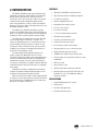
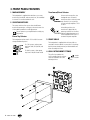
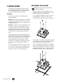
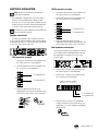
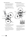
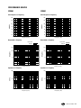
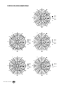
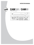
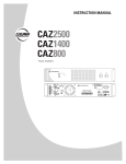
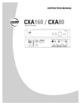
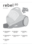
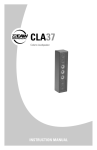
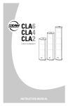
INSTRUCTION MANUAL
CIS961 and CIS991
High-Output Ceiling-Mounted Loudspeakers
1. SAFETY INSTRUCTIONS
1.
2.
3.
4.
5.
6.
7.
8.
9.
10.
11.
12.
13.
Read these instructions.
Keep these instructions.
Heed all warnings.
Follow all instructions.
Do not use this apparatus near water.
Clean only with a dry cloth.
Do not block any ventilation openings. Install in accordance with the
manufacturer’s instructions.
Do not install near any heat sources such as radiators, heat registers,
stoves, or other apparatus (including amplifiers) that produce heat.
Only use attachments/accessories specified by the manufacturer.
Refer all servicing to qualified service personnel. Servicing is required
when the apparatus has been damaged in any way, such as liquid has
been spilled or objects have fallen into the apparatus, the apparatus has
been exposed to rain or moisture, does not operate normally, or has been
dropped.
The entire sound system must be designed in compliance with the current
standards and laws regarding electrical systems.
When installing and using this apparatus, keep in mind the technical
specifications indicated in the dedicated section of the manual.
Exposure to high sound levels can cause permanent hearing loss. The
sound pressure level which leads to hearing loss varies considerably
from one person to another, and depends on the duration of exposure.
The U.S. Government’s Occupational Safety and Health Administration
(OSHA) has established the maximum sound pressure levels that can be
with stood without causing damage, which are shown in the table below.
According to the OSHA regulations, any exposure over the maximum
limits indicated in the table can reduce the hearing capacity of a person.
To prevent potentially dangerous exposure to high sound pressure levels,
anyone subjected to such levels must use suitable protection. When
a EAW Commercial product capable of producing high sound levels is
being used, it is therefore necessary to wear ear plugs or protective
earphones when the limits shown in the table are exceeded. Consult the
specifications provided in the instruction manual to know the maximum
sound pressure (SPL) the loudspeaker is capable of producing.
The exclamation point within an equilateral triangle is
intended to alert the user of the presence of important
operating and maintenance (servicing) instructions in
the literature accompanying the apparatus.
14. Rigging Precautions: When mounting or suspending EAW Commercial
loudspeaker enclosures, it is essential that load ratings, rigging
techniques, and special safety considerations be appropriate for the
installation. Use only the mounting/rigging points on the loudspeaker
enclosure intended for this purpose. The user must determine the load
requirements, dynamic loading, and any other contributing factors
affecting the loudspeaker installation. The user must determine the
proper design factor for specific applications and the required load rating
of the connection to structure. Comply with all applicable federal, state,
and local regulations.
EAW Commercial strongly recommends the following rigging system
practices:
• Documentation: Thoroughly document the mounting/rigging design
with detailed drawings and parts lists.
• Analysis: Have a licensed structural engineer or other qualified
professional review and approve the mounting/rigging design before its
implementation.
• Installation: Use personnel experienced and qualified for mounting/
rigging loudspeakers in accordance with and in compliance with all
federal, state and local regulations.
DANGER: Loudspeakers should be mounted or suspended only
by persons with knowledge of the proper hardware and rigging
techniques. Failure to follow these precautions may result in damage
to the equipment, personal injury, or death.
Duration per
day (hours)
Sound level
(dBA)
Typical example
8
90
Duo in a small club
6
92
4
95
3
97
2
100
1.5
102
1
105
0.5
110
0.25 or less
11 5
Subway train
Very loud classical music
Locomotive at 50 feet
Loudest parts at a rock concert
Contents
1. SAFETY INSTRUCTIONS....................................................2
2. INTRODUCTION...................................................................3
WARNING! This equipment has been designed
to be installed by qualified professionals only!
There are many factors to be considered when
installing professional sound reinforcement systems,
including mechanical and electrical considerations, as well
as acoustic coverage and performance. EAW Commercial
strongly recommends that this equipment be installed only by a
professional sound installer or contractor.
3. FRONT PANEL FEATURES..................................................4
4. REAR PANEL FEATURES.....................................................5
5. INSTALLING THE LOUDSPEAKER.....................................6
6. SPECIFICATIONS...............................................................10
7. OPTIONAL KITS.................................................................16
8. SERVICE INFORMATION..................................................19
9. EAW COMMERCIAL WARRANTY...................................19
Part No. 0023640 Rev. A 03/08
© 2008 LOUD Technologies Inc. All Rights Reserved.
– CIS961 and CIS991
2. INTRODUCTION
FEATURES
The CIS961 and CIS991 are high-output ceiling-mounted
loudspeakers, designed for fixed installation into high ceiling
plenum spaces or open structures. Utilizing four 5.25" LF
cone woofers, four 4" MF cone woofers, and a horn-mounted
compression driver, these loudspeakers deliver coherent
point-source reproduction, as well as superior low-frequency
dispersion. The result is superior full-range performance in any
distributed loudspeaker system.
• High speech intelligibility at high power levels
The CIS991 offers a broader high-frequency coverage
pattern than the CIS961. (Please refer to the polar diagrams on
pages 12–15.) Apart from this difference the two loudspeakers
are identical, and this instruction guide covers both models.
• 4 x 4" MF cone woofers
The loudspeakers are supplied with an integral 70V/100V
line transformer, rated to a maximum of 128 watts. Tap
settings are adjustable by means of a recessed rotary switch
on the front bezel, and allows selection of 128, 64, 32, and
16 watt taps at 70 V, and 128, 64, and 32 watt taps at 100 V.
In addition, the transformer can be bypassed, presenting an
8-ohm load to low-impedance systems.
The white powder-coated 18-gauge steel back can is
square in shape, and is designed to mount in a 24-inch
ceiling grid. The back can includes a recessed euroblock input
connector, with detachable mating plug, concealed behind a
hinged metal cover plate. A ceramic screw-terminal block is
also present. Four eye-bolts are supplied, and these need to be
screwed into the back can by the installer, prior to suspending
the assembly.
The baffle/can assembly is shipped with the transducers
installed. The powder-coated perforated steel grille is easily
installed once the wattage tap has been selected.
Optional installation kits include a 4-piece cable kit (AC-CK)
for suspension, and a 4-piece square trim ring kit (AC-TRK) that
dresses the baffle into suspended ceiling tile surrounds. (See
page 16 for more details of these kits.)
• High output and smooth low-frequency dispersion
• Fast and easy installation
• Seamless, deep-drawn back can
• Integrated 4-point mounting system
• 4 x 5.25" LF cone woofers
• 1" HF horn-mounted compression driver
• 70V/100V transformer built-in
• 128, 64, 32, and 16 watt taps at 70 V
• 128, 64, and 32 watt taps at 100 V
• 8 ohm setting on selector switch (direct)
• Removable grille for access to transformer taps
• Euroblock Phoenix-type input connector
• "BS5839 Part 8" compliant screw terminal inputs
• Through-outputs for easy parallel connections to other
loudspeakers
• Cable strain relief
• Input connection covers
• Optional 4-piece cable suspension kit (AC-CK)
• Optional 4-piece trim ring kit (AC-TRK) to dress the
installation into 24" x 24" and 600 mm x 600 mm
ceiling tile surrounds
APPLICATIONS
• Foreground/background music systems
• Paging systems
• Continuous-duty applications
• Sound reinforcement systems
CIS961 and CIS991 – 3. FRONT PANEL FEATURES
1. MAIN ASSEMBLY
Transformer/Direct Selector
The loudspeaker is supplied with the drivers, crossovers,
transformer, front baffle, and rear metal can, all assembled
in one unit. Do not disassemble this unit.
In the transformer position, the
loudspeaker uses an internal
transformer with a choice of power
taps. Set this if you are using a
constant voltage amplifier of 70 V
or 100 V.
2. SELECTOR SWITCHES
Two rotary switches allow you to select the different
transformer power taps, or to bypass the transformer. Use
a flat-ended screwdriver to make adjustments.
In the direct position, the
transformer is bypassed, the
power tap selector has no effect,
and the loudspeaker presents an
overall impedance of 8 ohm to a
conventional power amplifier.
Turn off power to your amplifier before making any
adjustments.
Power Tap Selector
The loudspeaker can be used in 70 V or 100 V constantvoltage distributed systems.
For 70 V systems, select power
taps from 16 W, 32 W, 64 W, and
128 W.
For 100 V systems, select power
taps from 32 W, 64 W and 128 W.
3. FRONT GRILLE
The loudspeaker is supplied with the front grille not
attached to the front baffle. It comes with an insulating
backing sheet already attached, to hide the baffle and
driver assembly from view.
4. GRILLE ATTACHMENT FITTINGS
The grille is attached to the
main assembly after the selector
switches have been set to the
desired positions.
1
2
3
4
– CIS961 and CIS991
washer
lock washer
screw
4. REAR PANEL FEATURES
5. EYEBOLTS
Terminal strip.
Four included eyebolts must be securely fitted to the metal
back can for the purpose of suspending the loudspeaker. All
four eyebolts must be used.
An optional mounting kit (AC-CK) is available that consists
of four 10-meter lengths of cable and suitable connectors.
6. INPUT CONNECTORS
The input connections to the loudspeaker are accessed by
moving two metal covers.
Phoenix (Euroblock)
connector.
OP
LO RU
TH +
IN
OP IN +
LO RU –
TH –
This four-pin input accepts
a push-in connector for easy
installation. Two terminals
allow connection to the output
of the power amplifier, and two
through-terminals are supplied to
allow passing the power output
to other loudspeakers.
This four-terminal connector
allows easy connection of the
audio lines by screw terminals.
(This is also suitable for
those installations requiring
compliance with BS5839,
part 8.) Two terminals allow
connection to the output of
the power amplifier, and two
through-terminals are supplied
to allow passing the power output to other loudspeakers.
Secure the connections with screws.
7. STRAIN RELIEF
This sliding screw clamp allows the wiring to and from the
loudspeaker to be secured. The clamp can also be removed,
and standard conduit fittings (not supplied) connected.
6
7
5
CIS961 and CIS991 – 5. INSTALLATION
The loudspeaker is designed to be securely suspended
from the four eyebolts fixed to the metal back can. It can
be suspended into the aperture of a standard suspended
ceiling, or suspended from open plenum spaces.
Placement
There are two considerations when deciding where to
place the loudspeaker:
Mechanical Installation
Note: Observe all local and national codes when
installing the loudspeaker.
Decide if you want to connect the loudspeaker to the
amplifier wiring before it is mounted in place, or if there is
enough access to the rear panel afterwards.
You can suspend the loudspeaker using your own safetycertified equipment, or purchase the optional cable
mounting kit AC-CK (more details are shown on page 16).
Location: When installing the loudspeaker in a suspended
ceiling with conventional ceiling tiles, the location of the
loudspeaker is determined in part by the support grid of the
suspended ceiling system.
Coverage: It is important to locate the loudspeaker in such
a way that the sound is evenly distributed over the entire
area. Keep in mind that the sound has farther to travel on
the outside edge of the coverage area for each individual
loudspeaker than directly below the loudspeaker, resulting
in a decrease in SPL at the outer edges of the listening
plane.
The loudspeaker placement should be designed such that
the edges of the coverage pattern for each loudspeaker are
at least touching. The more overlap that is provided (higher
density coverage), the more SPL the system is capable
of providing and the less variation in level as you move
around the area. The downside of higher density coverage,
of course, is that more loudspeakers are required for a
given area.
Note: The EAW website contains free PC software to help
you calculate the coverage for various loudspeakers and
room sizes. Please visit www.EAW.com/downloads and
look under "software" for the "coverage calculator."
All four eyebolts must be used to suspend the loudspeaker,
and the weight must be completely supported by the four
suspension cables, and not by the ceiling frame.
If you are suspending the loudspeaker into a suspended
ceiling, we recommend using the optional trim ring kit (ACTRK) to dress the loudspeaker surrounds into a standard
suspended ceiling aperture 24" x 24" or 600 mm x 600 mm.
More details of the trim ring kit are shown on page 18.
Trim ring
– CIS961 and CIS991
Electrical Installation
100 V connection example
1. Connect the 100 V terminal on the amplifier to the
IN + input connection on the loudspeaker.
Note: Observe all local and national codes when
installing the loudspeaker.
2. Connect the GND terminal on the amplifier to the
IN – input connection on the loudspeaker.
The loudspeaker is supplied with a strain-relief sliding
clamp for securing jacketed cable or flexible conduit.
If you are using 1/2 inch solid conduit or flexible armored
conduit, then the strain-relief can be removed and fittings
for securing solid conduit used instead (see page 9).
To Loudspeaker IN +
To Loudspeaker IN –
All connections to the loudspeaker must be made with
the power amplifier turned off.
Amplifier connections
The following examples of 70 V and 100 V connections
show an EAW Commercial CAM160, a typical mixer/amplifier.
Its speaker-level output is a screw terminal strip, with outputs
for 25 V, 70 V, 100 V, Ground, and 4 ohm.
3. Select the appropriate power tap on the
loudspeaker, from the outer ring marked 100V, and
make sure the other switch is set to "transformer."
Low impedance connections
70 V connection example
1. Connect the 70 V terminal on the amplifier to the
IN + input connection on the loudspeaker.
The following example of a low-impedance connection
uses a EAW Commercial CAZ2500 amplifier to power
the loudspeaker. This amplifier also uses a screwterminal output.
PUSH
INPUT
B
INPUT
CONNECTION
CAZ2500-AMPLIFIER
CAUTION
TO REDUCE THE RISK OF FIRE OR ELECTRIC SHOCK,
DO NOT EXPOSE THIS APPARATUS TO RAIN OR
MOISTURE. SEE INSTRUCTIONS BEFORE USING.
BREAKER
B (+)
B (--)
OFF
LINE
SERIAL /DATE CODE
ON
SUBSONIC
FILTER AT 30Hz
(BALANCED)
AMP MODE
GND
PUSH
A (--)
INPUT
A
MONO
STEREO
CHANNEL B BRIDGED CHANNEL A
B (+) B (-) (+)
MANUFACTURED IN CHINA
2004 LOUD TECHNOLOGIES INC.
"EAW" IS A REGISTERED TRADEMARK
OF LOUD TECHNOLOGIES INC.
(-) A (+) A (-)
BRIDGE
PUSH
INPUT
B
2. Connect the GND terminal on the amplifier to the
IN – connection on the loudspeaker.
INPUT
CONNECTION
A (+)
OFF
ON
CLIP LIMIT
LINE
(BALANCED)
CAUTION
TO REDUCE THE RISK OF FIRE OR ELECTRIC SHOCK,
DO NOT EXPOSE THIS APPARATUS TO RAIN OR
MOISTURE. SEE INSTRUCTIONS BEFORE USING.
1. Connect the A + terminal on the amplifier to the
CAZ2500-AMPLIFIER
IN + input connection on the loudspeaker.
BREAKER
OFF
LINE
ON
To Loudspeaker IN +
SUBSONIC
FILTER AT 30Hz
(BALANCED)
AMP MODE
PUSH
INPUT
A
To Loudspeaker IN –
MONO
STEREO
SERIAL /DATE CODE
2. Connect the A – terminal on the amplifier to the
IN – connection on the loudspeaker.
CHANNEL B BRIDGED CHANNEL A
B (+) B (-) (+)
(-) A (+) A (-)
BRIDGE
OFF
ON
CLIP LIMIT
LINE
(BALANCED)
3. Select the appropriate power tap on the
loudspeaker from the inner ring marked 70 V, and
make sure the other switch is set to "transformer."
To Loudspeaker IN –
To Loudspeaker IN +
3. Select the "direct" position on the loudspeaker
to bypass the power-tap transformer and run the
loudspeaker as a constant impedance loudspeaker
(8 ohm nominal).
CIS961 and CIS991 – Phoenix-type connections
Screw terminal connections
1. Loosen two locking screws (shown below) and
rotate the cover plate to gain access to the input
terminals. The loudspeaker is supplied with a
Phoenix-type connector pressed in place.
2. Pass the cables through the strain-relief clamp.
3. Pull off the supplied Phoenix-type connector
and attach the loudspeaker cables using a small
screwdriver. The two inner connections are labeled
IN + and IN –.
OP
LO RU
TH +
IN
OP IN +
LO RU –
TH –
1. Loosen two locking screws and rotate the cover
plate to gain access to the screw terminals.
2. Pass the cables through the strain-relief clamp.
3. Secure the loudspeaker cables using a small
screwdriver. The two inner connections are labeled
IN + and IN –.
From amplifier
To next
loudspeaker
Locking screws
Locking screws
To next
loudspeaker
Loop
Thru –
IN – IN +
Loop
Thru +
From amplifier
4. If connecting another loudspeaker in a distributed
system (in parallel), connect the speaker cable
running to the next speaker to the outer “+” and
“–” terminals labeled LOOP THRU.
Close-up view
5. Press the Phoenix-type connector in place.
4. If connecting another loudspeaker in a distributed
system (in parallel), connect the speaker cable
running to the next speaker to the outer “+” and
“–” terminals labeled LOOP THRU.
6. Tighten the strain relief screws to secure the
speaker cable or flexible conduit. Give the cables
some slack before securing the strain-relief clamp.
Close the terminal cover plate and tighten both
locking screws firmly.
5. Tighten the strain relief screws to secure the
speaker cable or flexible conduit. Give the cables
some slack before securing the strain-relief clamp.
Close the terminal cover plate and tighten both
locking screws firmly.
– CIS961 and CIS991
Installation with conduit
1. Remove the two screws holding the strain relief
onto the rear cover, and remove the strain relief
assembly. Keep it safe, in case you need it again.
2. Use a threaded conduit
set-screw coupler
(not supplied): For
1/2" conduit, use
Thomas&Betts Steel
City model TC221-SC
(or UL listed equivalent).
3. If you are using flexible
conduit, then use
Thomas&Betts Steel City
model XC241 flexible
conduit fitting (or UL listed
equivalent).
4. Insert the new coupler into the hole exposed by
removing the strain relief assembly. Fasten the
coupler using the nut supplied with the coupler. It
will help to remove the four side screws holding
the cover plate assembly to the loudspeaker metal
back can, so you can tighten the coupler's nut.
Setting the Taps
1. Set the tap selector switch, located on the front of
the loudspeaker. In the example shown here, the
tap is set to 32 W for a 70 Volt system, or 64 W
for a 100 V system.
CAUTION: Make sure that you do not overload
the amplifier. This may cause overheating to
the amplifier, and possible damage to your
loudspeakers. To avoid overloading, make sure that
the selected taps on the loudspeakers add up to no
more than 80% of the rated power of the amplifier
being used.
2. If the speaker is being used in a low-impedance
system, use the direct position. This bypasses the
tapped transformer, and the amplifier load will be
an average impedance of 8 ohms. If you are using
the thru connections to power other loudspeakers,
note that the connections are in parallel. Make
sure that the total impedance is not lower than
the minimum impedance that your amplifier can
handle.
CAUTION: To prevent the risk of electric shock,
never touch the bare wires coming from the output
terminals of the amplifier when it is switched on.
When the connections have been made, make sure
the input cover plates are correctly in place.
5. Push the speaker cable
through the conduit
coupler, and insert
your conduit into the
coupler. Tighten the
locking screw firmly.
(Or twist flexible
cable onto the coupler
shown in step 3.)
6. Attach the wires to the
supplied Phoenix-type
connector or the screw
terminals as detailed
on the previous page, and close and lock the input covers.
CIS961 and CIS991 – 6. SPECIFICATIONS
Model
Part Number
LF/MF
HF Loading
CIS961
0026852
4 x 5.25" cone and
4 x 4.5" cone
Sealed
1" exit, 1.75" voice coil
compression driver
Horn
CIS991
0026853
4 x 5.25" cone and
4 x 4.5" cone
Sealed
1" exit, 1.75" voice coil
compression driver
Horn
Operating Range (–10 dB)
82 Hz – 20 kHz
79 Hz – 20 kHz
Horizontal Beamwidth - Nominal
60 degrees
80 degrees
Vertical Beamwidth - Nominal
60 degrees
80 degrees
Axial Sensitivity (whole space SPL)
93 dB
92 dB
Input Impedance - Nominal
8 ohm
8 ohm
Input Impedance - Minimum
7.2 ohm @ 1000 Hz
6.4 ohm @ 1300 Hz
LF/MF Loading
HF
70 V wattage taps
128, 64, 32, 16 watts
128, 64, 32, 16 watts
100 V wattage taps
128, 64, 32 watts
128, 64, 32 watts
Recommended High-pass filter
=> 60 Hz, 12 dB/octave
Butterworth
=> 60 Hz, 12 dB/octave
Butterworth
Power Handling
200 W, 40 Vrms @ 8 ohms
200 W, 40 Vrms @ 8 ohms
Maximum SPL, Average
(whole space SPL)
115 dB
114 dB
Maximum SPL, Peak
(whole space SPL)
121 dB
120 dB
Height (front face)
Width (front face)
Depth (from face, backwards)
Weight
22.60"/574.1 mm
22.60"/574.1 mm
9.05"/230.0 mm
48 lb/22 kg
22.60"/574.1 mm
22.60"/574.1 mm
9.05"/230.0 mm
48 lb/22 kg
Optional Accessories
AC-TRK Trim Ring Kit
AC-CK Cable Kit
Part number
0025528
0025530
22.60 in
574.1 mm
9.05 in
230.0 mm
9.55 in
242.5 mm
22.60 in
574.1 mm
9.55 in
242.5 mm
DISCLAIMER
EAW Commercial continually engages in research related to product improvement, new materials, and production methods.
Design refinements are introduced into existing products without notice as a routine expression of that philosophy. For this
reason, any current EAW Commercial product may differ in some respect from its published description, but will always equal or
exceed the original design specifications unless otherwise stated.
“EAW Commercial” is a trademark of LOUD Technologies Inc. All other brand names mentioned are trademarks or registered
trademarks of their respective holders, and are hereby acknowledged.
10 – CIS961 and CIS991
Performance graphs
CIS991
Axial Response vs Frequency
Axial Response vs Frequency
120
120
110
110
100
100
dB SPL
dB SPL
CIS961
90
80
70
90
80
70
60
60
10
100
1000
10k 20k
10
100
Frequency (Hz)
1000
Beamwidth vs Frequency
Beamwidth vs Frequency
Horizontal
Vertical
360
360
100
100
Degrees
Degrees
Horizontal
Vertical
10
10
1
1
100
1000
10k
100
20k
1000
10k
20k
Frequency (Hz)
Frequency (Hz)
Impedance vs Frequency
Impedance vs Frequency
100
Ohms
100
Ohms
10k 20k
Frequency (Hz)
10
10
1
1
10
100
1000
Frequency (Hz)
10k 20k
10
100
1000
10k 20k
Frequency (Hz)
CIS961 and CIS991 – 11
Vertical Polar diagrams CIS961
120°
150°
1600 Hz
2000 Hz
180°
2500 Hz
3150 Hz
210°
240°
120°
120°
150°
150°
250 Hz
4000 Hz
315 Hz
180°
400 Hz
5000 Hz
180°
6300 Hz
500 Hz
8000 Hz
210°
210°
240°
240°
120°
120°
150°
150°
630 Hz
800 Hz
180°
1000 Hz
10000 Hz
12500 Hz
180°
16000 Hz
1250 Hz
210°
210°
240°
12 – CIS961 and CIS991
240°
Vertical Polar diagrams CIS991
120°
150°
1600 Hz
2000 Hz
180°
2500 Hz
3150 Hz
210°
240°
120°
120°
150°
150°
250 Hz
4000 Hz
315 Hz
180°
400 Hz
5000 Hz
180°
6300 Hz
500 Hz
8000 Hz
210°
210°
240°
240°
120°
120°
150°
150°
630 Hz
800 Hz
180°
1000 Hz
10000 Hz
12500 Hz
180°
16000 Hz
1250 Hz
210°
210°
240°
240°
CIS961 and CIS991 – 13
Horizontal Polar diagrams CIS961
120°
150°
1600 Hz
2000 Hz
180°
2500 Hz
3150 Hz
210°
240°
120°
120°
150°
150°
250 Hz
4000 Hz
315 Hz
180°
400 Hz
5000 Hz
180°
6300 Hz
500 Hz
8000 Hz
210°
210°
240°
240°
120°
120°
150°
150°
630 Hz
800 Hz
180°
1000 Hz
10000 Hz
12500 Hz
180°
16000 Hz
1250 Hz
210°
210°
240°
14 – CIS961 and CIS991
240°
Horizontal Polar diagrams CIS991
120°
150°
1600 Hz
2000 Hz
180°
2500 Hz
3150 Hz
210°
240°
120°
120°
150°
150°
250 Hz
4000 Hz
315 Hz
180°
400 Hz
5000 Hz
180°
6300 Hz
500 Hz
8000 Hz
210°
210°
240°
240°
120°
120°
150°
150°
630 Hz
800 Hz
180°
1000 Hz
10000 Hz
12500 Hz
180°
16000 Hz
1250 Hz
210°
210°
240°
240°
CIS961 and CIS991 – 15
7. OPTIONAL KITS
4. Pull on the free ends to take up the slack and thus
secure the hook/latch assemblies.
Two kits are available for the loudspeaker. One is a
mounting kit, and one is a trim ring kit. Please contact your
dealer or EAW Commercial for ordering details.
5. Note: The hexagonal locking
device has an arrow engraved on
one side. This must be pointing
down when installing.
AC-CK cable mounting kit
This kit consists of four 10-meter lengths of wire cable
with a crimped-on hook at one end. A small locking device
allows the length to be easily adjusted, so you can hang
the loudspeaker accurately in position in a suspended
ceiling, for leveling, or setting at an angle.
You will need an assistant to help
hold the loudspeaker in position
and support its weight.
Pass the free end of the cable through the outside
hole of the top end of a hexagonal locking device,
through a loudspeaker eyebolt, and back up
through the center hole of the locking device.
Loudspeaker suspended
by four cables
Close-up view of the
hexagonal locking
device
1. Find the location where you want the loudspeaker
to be suspended.
2. Use suitable flying points above the loudspeaker.
These may be ceiling beams or suitable eyebolt
hardware. (The dimensioned drawing at the bottom
of page 10 shows the location of the eyebolts.)
3. Pass the free end of each cable over the support
beam/structure and loop it through the hook/latch.
Fitting the hook/latch
to a support
Fitting the cable to an eyebolt
16 – CIS961 and CIS991
6. Pull up on the free cable ends until the loudspeaker
is suspended at the correct height. (The hexagonal
locking devices will stop the cables from pulling
through and lowering the loudspeaker.)
Pull the free end
to take up slack
7. To lower the loudspeaker, first support its weight
with the help of your assistant until the cables
go slack. Use a small screwdriver to push up on
the inner cylindrical sleeve inside the hexagonal
locking device, and at the same time, gently feed
more cable back through to increase the loop until
the correct height is achieved.
Use a small screwdriver or point to
push up the inner sleeve and release
the cable
CIS961 and CIS991 – 17
AC-TRK ceiling-mount trim ring kit
INSTALLATION
The AC-TRK is a 4-piece square trim ring kit that dresses
the baffle into suspended ceiling tile surrounds (24" x 24").
The trim ring kit can also fit into 600 mm x 600 mm square
ceiling tile surrounds by simply removing the small knock-off
tab spacers along each edge.
1. Gently drop the assembled square into the
suspended ceiling, with the smooth sides facing
down.
The kit consists of four identical sides that can be joined
together to form a square. This fills the space between the
loudspeaker sides and the frame of the suspended ceiling.
PREPARATION and Assembly
1. For installation into 24" x 24" ceiling surrounds,
leave the tabs on and skip the next step.
2. For installation into 600mm x 600mm ceiling
surrounds, remove all tabs from each of the sides.
You can do this with a sharp knife or chisel, or
by pressing the sides against the sharp edge of a
table top, for example.
3. On a flat surface, join the four sides together to
form a square, and tighten the phillips screws at
each corner.
Installing the trim ring into
the ceiling frame
2. Carefully adjust the length of the four suspension
cables until the loudspeaker is lowered into
the trim ring. The weight must be completely
supported by the cables, not by the suspended
ceiling frame. (A cable mounting kit AC-CK is
available, consisting of four cables, each with a
latch hook and a locking device.)
Removable
Tabs
Assembled Trim Ring
Screw
Removable
Tab
Removable
Tab
Enlarged view of corner
Installing the loudspeaker into the trim ring
18 – CIS961 and CIS991
8. SERVICE INFORMATION
9. EAW COMMERCIAL WARRANTY
In the event that your loudspeaker should require servicing,
please follow these instructions:
Warranty: LOUD Technologies Inc. requires its authorized
EAW Commercial distributors to abide by the following
warranty terms for all EAW Commercial brand products
(all dates are from the date of delivery from an Authorized
EAW Commercial Distributor to the end user/installation
site): Loudspeakers – 5 years; Active Electronics – 5 years;
Accessories – 2 years.
1. Call EAW Commercial Tech Support at 1-888-337-7404,
7 am to 5 p.m. PST (Monday-Friday), to verify the problem
and obtain a Return Authorization (RA) Number. Be sure to
have the serial number of the unit when you call. You must
have a Return Authorization Number in order to obtain
warranty service at an authorized service center. You can
also e-mail EAW Commercial Tech Support at:
[email protected]
2. Pack the unit in its original packaging. THIS IS VERY
IMPORTANT. LOUD Technologies is not responsible for
any damage that occurs during shipping due to nonconventional packaging. Original packaging helps to
minimize the possibility of shipping damage.
3. Include a legible note stating your name, (no P.O. boxes),
daytime phone number, Return Authorization Number, and
a detailed description of the problem, including how we
can duplicate it.
4. Write the Return Authorization Number in BIG BOLD PRINT
on the top of the box.
5. Tech Support will tell you where to ship the unit when you
call for an RA Number. We suggest insurance for all forms
of cartage.
What Is Covered: Defects in workmanship and materials
and against malfunctions. EAW Commercial distributors
must remedy all such defects and malfunctions without
charge for parts or labor if the warranty applies. Final
determination of warranty coverage lies solely with each
authorized EAW Commercial distributor.
What Is Not Covered: This warranty does not extend
to damage or malfunctions resulting from, but not limited
to, shipment, improper installation, misuse, neglect,
abuse, normal wear, accident, or to any product on
which the serial number has been modified or removed.
Exterior defects in or damage to the exterior appearance
are specifically excluded from this warranty. EAW
Commercial distributors shall not be liable for incidental
or consequential damages resulting from the use of EAW
Commercial products. Repairs and/or modifications by
other than an Authorized EAW Commercial Distributor
automatically voids this warranty.
Correct Disposal of this product: This symbol indicates that this product should not be disposed of with your household waste, according to the WEEE Directive
(2002/96/EC) and your national law. This product should be handed over to an authorized collection site for recycling waste electrical and electronic equipment (EEE).
Improper handling of this type of waste could have a possible negative impact on the environment and human health due to potentially hazardous substances that are
generally associated with EEE. At the same time, your cooperation in the correct disposal of this product will contribute to the effective usage of natural resources.
For more information about where you can drop off your waste equipment for recycling, please contact your local city office, waste authority, or your household waste
disposal service.
CIS961 and CIS991 – 19
EAW Commercial A LOUD Technologies Inc. Company
EAW Commercial | One Main Street | Whitinsville, MA 01588 USA | TEL toll free within US/Canada 888.337.7404
TEL outside US 425.892.6503 | FAX 425.485.1152 | www.eaw.com
© 2008 LOUD Technologies Inc. All Rights Reserved.