1
Matrix Switcher
Operating Instructions
Model Nos.
WJ-SX650 Series
OPE
RAT
E
OP
IF CO ERAT
LLIN E LED
G FA
W
N M ILL BL
ALFU INK
NCTI
ONS
Matrix
Switc
her W
J-SX
650
Before attempting to connect or operate this product,
please read these instructions carefully and save this manual for future use.
ENGLISH VERSION
Caution:
Before attempting to operate this product, please read the
label on the surface of the unit.
CAUTION
RISK OF ELECTRIC SHOCK
DO NOT OPEN
For Canada
This Class A digital apparatus complies with Canadian
ICES-003.
For U.S.A
CAUTION: TO REDUCE THE RISK OF ELECTRIC SHOCK,
DO NOT REMOVE COVER (OR BACK).
NO USER-SERVICEABLE PARTS INSIDE.
REFER SERVICING TO QUALIFIED SERVICE PERSONNEL.
SA 1965
The lightning flash with arrowhead symbol,
within an equilateral triangle, is intended to
alert the user to the presence of uninsulated
"dangerous voltage" within the product's
enclosure that may be of sufficient magnitude to constitute a risk of electric shock to
persons.
The exclamation point within an equilateral
triangle is intended to alert the user to the
presence of important operating and maintenance (servicing) instructions in the literature accompanying the appliance.
SA 1966
Power disconnection. Unit with or without
ON-OFF switches have power supplied to
the unit whenever the power cord is inserted
into the power source; however, the unit is
operational only when the ON-OFF switch is
in the ON position. The power cord is the
main power disconnect for all units.
NOTE: This equipment has been tested and found to comply with the limits for a Class A digital device, pursuant to
Part 15 of the FCC Rules. These limits are designed to provide reasonable protection against harmful interference
when the equipment is operated in a commercial environment. This equipment generates, uses, and can radiate
radio frequency energy and, if not installed and used in
accordance with the instruction manual, may cause harmful
interference to radio communications.
Operation of this equipment in a residential area is likely to
cause harmful interference in which case the user will be
required to correct the interference at his own expense.
FCC Caution: To assure continued compliance, (example use only shielded interface cables when connecting to computer or peripheral devices). Any changes or modifications
not expressly approved by the party responsible for compliance could void the user’s authority to operate this equipment.
The serial number of this product may be found on the surface of the unit.
You should note the serial number of this unit in the space
provided and retain this book as a permanent record of your
purchase to aid identification in the event of theft.
Model No.
Serial No.
WARNING:
• This apparatus must be earthed.
• To prevent fire or electric shock hazard, do not expose this apparatus to rain or moisture.
• The apparatus shall not be exposed to dripping or splashing and that no objects filled with liquids, such as vases, shall be placed
on the apparatus.
2
IMPORTANT SAFETY INSTRUCTIONS
1) Read these instructions.
2) Keep these instructions.
3) Heed all warnings.
4) Follow all instructions.
5) Do not use this apparatus near water.
6) Clean only with dry cloth.
7) Do not block any ventilation openings. Install in accordance with the manufacturer's instructions.
8) Do not use near any heat sources such as radiators, heat registers, stoves, or other apparatus (including amplifiers) that
produce heat.
9) Do not misuse the polarized or grounding-type plug. A polarized plug has two blades with one wider than the other. A
grounding-type plug has two blades and a third grounding prong. The wide blade or the third prong are provided for your
safety. If the provided plug does not fit into your outlet, consult an electrician for replacement of the obsolete outlet.
10) Protect the power cord from being stepped on or pinched particularly at plugs, convenient receptacles and the points
where they exit from the apparatus.
11) Only use attachments/accessories specified by the manufacturer.
12) Use only with the cart, stand, tripod, bracket, or table specified by the manufacturer, or sold with the apparatus. When a
cart is used, use caution when moving the cart/apparatus combination to avoid injury from tip-overs.
S3125A
13) Unplug this apparatus during lightning storms or when unused for long periods of time.
14) Refer all servicing to qualified service personnel. Servicing is required when the apparatus has been damaged in any way,
such as when the power-supply cord or plug is damaged, liquid has been spilled or objects have fallen into the apparatus,
the apparatus has been exposed to rain or moisture, does not operate normally, or has been dropped.
3
CONTENTS
IMPORTANT SAFETY INSTRUCTIONS ............................ 3
LIMITATION OF LIABILITY ................................................ 5
DISCLAIMER OF WARRANTY .......................................... 5
TRADEMARKS AND REGISTERED TRADEMARKS ........ 5
PRECAUTIONS .................................................................. 6
ABOUT THESE OPERATING INSTRUCTIONS ................ 7
PREFACE ........................................................................... 8
FEATURES ......................................................................... 8
MAJOR OPERATING CONTROLS AND
THEIR FUNCTIONS ........................................................... 9
■ WJ-SX650 Matrix Switcher/
WJ-SX650U Card Cage ................................................ 9
■ Video Input Board WJ-PB65C32 ................................ 11
■ Video Output Board WJ-PB65M16 ............................. 12
■ Monitor Display Information ........................................ 13
■ System Controller Display Information ....................... 14
INSTALLATIONS ............................................................. 16
■ Checking Board Composition ..................................... 16
■ Switch Settings for Video Input Main Board ............... 17
■ Switch Settings for Video Output Main Board ............. 18
■ Mounting Video Input and Output Boards ................... 19
■ Board Mounting Procedure ......................................... 20
■ Installing the Main Unit ............................................... 21
CONNECTIONS ............................................................... 22
■ Basic System Connections ......................................... 23
■ Expanded System Connections .................................. 24
■ Card Cage Connections ............................................. 26
■ Camera Connections .................................................. 27
■ RS-485 Camera Connections ..................................... 27
■ Monitor Connections ................................................... 29
■ PC Connection ............................................................ 29
■ Recorder Connection .................................................. 30
■ Recorder Settings ....................................................... 34
■ System Controller Connection .................................... 34
■ Alarm Sensor Connections ......................................... 36
■ External Device Connections ...................................... 36
■ System Status Check ................................................. 37
SETUP PROCEDURE ...................................................... 38
WJ-SX650 SERIES ADMINISTRATOR CONSOLE ......... 40
■ System Requirements of a PC ................................... 40
■ Installation and Uninstallation ..................................... 40
■ Starting Up .................................................................. 41
■ Window Details ........................................................... 41
■ Tooltip Details ............................................................. 42
■ Factory Default Settings of WJ-SX650 Series
Administrator Console ................................................ 45
SETUP MENU (OSD) ....................................................... 48
■ Basic Operations ........................................................ 48
■ TIME & DATE ............................................................. 49
■ ALARM ....................................................................... 49
■ RECORDER ............................................................... 50
■ SYSTEM ..................................................................... 52
■ INFORMATION ........................................................... 54
■ LANGUAGE ................................................................ 54
LOGIN AND LOGOUT ...................................................... 55
■ Operator Registration ................................................ 55
■ Power-on/off ............................................................... 56
■ Operation Start (Login) ............................................... 56
■ Operation End (Logout) .............................................. 56
■ Operation Start/End (Auto Login/Logout) ................... 56
4
MONITOR CONTROL ...................................................... 57
■ Monitor Selection ........................................................ 57
■ Monitor Lock ............................................................... 57
CAMERA CONTROL ........................................................ 58
■ Camera Selection ....................................................... 58
■ Camera Selection Recall ............................................ 58
■ Preset Position Control ............................................... 58
■ All Cameras Control .................................................... 59
RECORDER CONTROL ................................................... 60
■ Playback ..................................................................... 60
■ Manual Recording ....................................................... 60
■ Multiscreen Display ..................................................... 60
■ Search Playback ......................................................... 60
■ Playing the Latest Recorded Image ............................ 60
■ Recorder Control End ................................................. 61
■ Recorder Selection ..................................................... 61
RUNNING SEQUENCE .................................................... 62
■ Descriptions of Sequence ........................................... 62
■ Tour Sequence ........................................................... 64
■ Group Sequence/Preset ............................................. 64
■ Sequence Pause ........................................................ 65
■ Sequence Stop ........................................................... 65
ALARM DESCRIPTIONS ................................................. 66
■ Alarm Occurrence ....................................................... 66
■ Alarm Modes ............................................................... 67
■ Video Loss .................................................................. 67
ALARM CONTROL ........................................................... 68
■ Alarm Acknowledgement (ACK) ................................. 68
■ Camera Control .......................................................... 68
■ Alarm Picture Change ................................................. 68
■ Alarm Individual Reset ................................................ 68
■ Alarm Monitor Reset ................................................... 68
■ Alarm All Reset ........................................................... 68
■ Return to Alarm Mode Status ..................................... 69
■ Alarm Suspension ....................................................... 69
■ Alarm History Display ................................................. 69
TIMER DESCRIPTIONS ................................................... 71
■ Timer Event ................................................................ 71
■ Camera Event ............................................................. 71
TERMINAL MODE OPERATION ...................................... 73
■ Lists of Operations and Functions .............................. 73
■ Menu Flow (WV-CU950/650) ...................................... 84
OPERATION (OTHER THAN TERMINAL MODE) ........... 85
■ PS·Data Mode Operations .......................................... 85
■ Connections of Matrix Switchers (WJ-SX650 Series)
and a PS·Data System Controller ............................... 86
■ Controlling from a Web Browser Accessing a
Recorder ..................................................................... 86
■ Controlling from a PC ................................................. 86
GLOSSARY ...................................................................... 87
TROUBLESHOOTING ...................................................... 89
■ Matrix Switcher WJ-SX650 Series ............................... 89
■ WJ-SX650 Series Administrator Console .................... 93
■ Power Cord, Connectors, and Power Plug ................. 94
SPECIFICATIONS ............................................................ 95
STANDARD ACCESSORIES ........................................... 97
LIMITATION OF LIABILITY
THIS PUBLICATION IS PROVIDED "AS IS" WITHOUT WARRANTY OF ANY KIND, EITHER EXPRESS OR IMPLIED,
INCLUDING BUT NOT LIMITED TO, THE IMPLIED WARRANTIES OF MERCHANTABILITY, FITNESS FOR ANY PARTICULAR PURPOSE, OR NON-INFRINGEMENT OF THE
THIRD PARTY’S RIGHT.
THIS PUBLICATION COULD INCLUDE TECHNICAL INACCURACIES OR TYPOGRAPHICAL ERRORS. CHANGES
ARE ADDED TO THE INFORMATION HEREIN, AT ANY
TIME, FOR THE IMPROVEMENTS OF THIS PUBLICATION
AND/OR THE CORRESPONDING PRODUCT (S).
DISCLAIMER OF WARRANTY
IN NO EVENT SHALL MATSUSHITA ELECTRIC INDUSTRIAL CO., LTD. BE LIABLE TO ANY PARTY OR ANY PERSON, EXCEPT FOR CERTAIN WARRANTY PROGRAM
OFFERED BY THE LOCAL DEALER OF PANASONIC, FOR
THE CASES INCLUDING BUT NOT LIMITED TO BELOW:
(1) ANY DAMAGE AND LOSS, INCLUDING WITHOUT LIMITATION, DIRECT OR INDIRECT, SPECIAL, CONSEQUENTIAL OR EXEMPLARY, ARISING OUT OF OR
RELATING TO THE PRODUCT;
(3) UNAUTHORIZED DISASSEMBLY, REPAIR OR MODIFICATION OF THE PRODUCT BY THE USER;
(4) INCONVENIENCE OR ANY LOSS ARISING WHEN
IMAGES ARE NOT DISPLAYED, DUE TO ANY REASON
OR CAUSE INCLUDING ANY FAILURE OR PROBLEM
OF THE PRODUCT;
(5) ANY PROBLEM, CONSEQUENTIAL INCONVENIENCE,
OR LOSS OR DAMAGE, ARISING OUT OF THE SYSTEM COMBINED BY THE DEVICES OF THIRD PARTY;
(2) PERSONAL INJURY OR ANY DAMAGE CAUSED BY
INAPPROPRIATE USE OR NEGLIGENT OPERATION
OF THE USER;
TRADEMARKS AND REGISTERED TRADEMARKS
• Microsoft, Windows and Windows XP are registered
trademarks of Microsoft Corporation in the U.S. and/or
other countries.
• Intel and Pentium are registered trademarks of Intel
Corporation or its subsidiaries in the United States and
other countries.
• Other company names and product names appearing
in this document are registered trademarks or trademarks of the company concerned.
5
PRECAUTIONS
• Refer all work related to the installation of this apparatus to qualified service personnel or system
installers.
• Do not block the ventilation opening or slots on the
cover.
To prevent the apparatus from overheating, place it at
least 5 cm {2 inches} away from the wall.
• Do not drop metallic parts through slots.
This could permanently damage the apparatus. Turn
the power off immediately and contact qualified service
personnel for service.
• Do not attempt to disassemble the apparatus.
To prevent electric shock, do not remove screws or
covers.
There are no user-serviceable parts inside. Contact
qualified service personnel for maintenance.
• Do not strike or give a strong shock to the unit.
It may cause damage or allow water to enter the unit.
• Do not expose the apparatus to water or moisture.
Do not try to operate it in wet areas.
Take immediate action if the apparatus gets wet. Turn
the power off and refer servicing to qualified service
personnel. Moisture can damage the apparatus and
also cause electric shocks.
• Built-in backup battery
Before the first use, charge the built-in backup battery
(lithium battery) by turning on the power for 48 hours or
more. If it is not charged enough, in a case where the
power goes down, the internal clock may keep bad
time or the operative condition may be different to that
before the electric power failure.
The built-in battery life is approximately 5 years as an
indication of replacement. (This is just an indication of
replacement. We are not providing any guarantee of the
built-in battery lifetime. Replacement cost of the built-in
battery is not covered by the warranty even if it needs
to be done within the warranty period.) Ask the shop
where you purchased the unit when replacement of the
battery is required.
• Cooling Fan
Turn the power off when cleaning the unit. Otherwise it
may cause injuries.
The cooling fan will operate for approximately 30 000
hours. Replacement costs of the cooling fan are not
covered by the warranty even if it needs to be done
within the warranty period.
6
• Cleaning
Turn the power off when cleaning the unit. Otherwise it
may cause injuries.
Do not use strong or abrasive detergents when cleaning the apparatus body.
Use a dry cloth to clean the apparatus when it is dirty.
When the dirt is hard to remove, use a mild detergent
and wipe gently.
• Do not operate the apparatus beyond its specified
temperature, humidity, or power source ratings.
Use the apparatus under conditions where temperatures are between –10 °C and + 50 °C {14 °F to 122 °F},
and humidity below 90 %.
The apparatus may be not linked to a network after
turning on in a cold atmosphere between –10 °C and 0
°C {14 °F to 32 °F}. Wait approximately 10 minutes until
the inside temperature has risen to 0 °C {32 °F}, it can
be linked to a network.
The input power source for this apparatus is 120 V AC,
60 Hz.
• Place the unit horizontally on a level surface. Do not
place the unit in an upright position. When stacking
multiple units, clear a space of more than 5 cm {2
inches} from both sides, the top, the bottom and the
rear of the units.
• Pay attention to static electricity
Make certain to keep boards inside the anti-static sack
until it is installed.
Put your hand on a metallic surface, other than the
boards to discharge static electricity before installation.
Do not touch components mounted on the boards
directly by hand.
Hold only both edges of the boards when installing.
• Do not use any power cord other than the one supplied.
• Only use the apparatus indoors.
Do not install it in places where the apparatus is
exposed to sunlight for long periods of time or near air
conditioning equipment. This will cause deformation,
discoloration, breakdown or malfunction.
• We recommend that you make a note of your settings and save them. This will help when you are
required to change the system configuration, or
when unexpected trouble or failure occurs.
• Distributing, copying, disassembling, reverse compiling, reverse engineering, and also exporting in
violation of export laws of the software provided
with this product, is expressly prohibited.
ABOUT THESE OPERATING INSTRUCTIONS
These operating instructions are classified roughly as follows:
• Operations (pages xx, xx, xx and xx)
Contains how to operate the system. These descriptions are intended for operators.
Note: Before operation, be sure to read safety instructions on p. 3 IMPORTANT SAFETY INSTRUCTIONS
and p. xx PRECAUTIONS.
This document uses the following terms for classification of devices.
The (This ) unit: Matrix Switcher WJ-SX650
Video input board: Video Input Board WJ-PB65C32
Video output board: Video Output Board WJ-PB65M16
Recorder: Digital Disk Recorder WJ-HD300/WJ-HD300
A Series
• Preparations (pages xx, xx, xx and xx)
Contains the required preparations including installation, connections, and setup procedures. These
descriptions are intended for installers and system
administrators.
Classification of digital disk recorders are as follows.
Term
Model Nos.
Remarks on Model Nos.
WJ-HD300 Series
WJ-HD316, WJ-HD309
Begins with "WJ-HD316".
WJ-HD300A Series
WJ-HD316A, WJ-HD309A
Begins with "WJ-HD316A".
7
PREFACE
Matrix Switcher WJ-SX650 Series (or SX650 Series) are
designed for a surveillance control system. WJ-SX650
Series (or SX650 Series) is the general term of following
models.
Matrix Switcher WJ-SX650 (Video Input Board WJPB65C32 x 1 and Video Output Board WJ-PB65M16 x 1
have been installed.)
Card Cage WJ-SX650U (For additional installation of video
input boards and video output boards)
Video Input Board WJ-PB65C32
Video Output Board WJ-PB65M16
Expansion Cable Kit WJ-CA65L20K/WJ-CA65L07K
D-sub/BNC Video Cable WJ-CA68
FEATURES
• Up to 256 cameras, 32 monitors connectable
• Remote control of optional external devices
If you connect System Controller WV-CU950, WVCU650, WV-CU360C and/or WV-CU360CJ to this product, remote control of cameras, lenses, pan/tilt heads,
and recorders (Digital Disk Recorder*) will be available.
* Refer to p. xx for details on model numbers.
If you connect a personal computer (PC) to this product, control and system setup with WJ-SX650 Series
Administrator Console will be available.
• Authentication by user ID's, passwords, and level
settings.
User ID's and passwords are assignable to users to
prevent inappropriate operations. In addition, the settings of level, camera access, and recorder access can
determine available functions, cameras, and recorders
for each user.
• Images of two or more cameras can be displayed on
one monitor.
Spot mode: A selected camera image is continuously
displayed on a selected monitor.
Sequence mode: Images of two or more cameras are
sequentially displayed on a desired monitor (or
monitors).
8
• Timer event and camera event can be scheduled.
Notes:
• Refer to p. 34 for details on timer event.
• Refer to p. 35 for details on camera event
• Alarm operation and alarm event can be scheduled.
Notes:
• Refer to p. 29 for details on alarm operation.
• Refer to p. 30 for details on alarm event
• With recorder connection, recorder control such as
recording and playback are available.
Camera images can be recorded.
Recorded images can be played back.
Camera images can be displayed in multiscreen segments.
MAJOR OPERATING CONTROLS AND THEIR FUNCTIONS
■ WJ-SX650 Matrix Switcher/WJ-SX650U Card Cage
● Front View
<Front panel attached>
<Front panel detached>
w
t
RESET
No.
MODE
PULL
r
OPERATE
POWER
OPERATE LED WILL BLINK
IF COOLING FAN MALFUNCTIONS
ON
OFF
TEST
RESET
Matrix Switcher WJ-SX
MODE
y
650
q
e
Normally, do not touch.
(Reserved for service personnel)
This is the illustration of WJ-SX650.
q Operation Indicator (OPERATE)
• This indicator is lighting while power is supplied to the
unit.
• This indicator blinks when the cooling fan has a trouble.
(Refer to p. 96.)
w Front Panel Fixing Screws
Before you press the power switch or install boards into
the expansion slot, these screw are removed to detach
the front panel
e Power Switch
r Expansion Slot
Optional video input or output main board is installed.
(Video Input Board WJ-PB65C32 or Video Output Board
WJ-PB65M16)
For WJ-SX650U, optional video input main board is
installed. (Video Input Board WJ-PB65C32)
t Video Input Board*
This is a video input main board. This board controls
cameras and alarm input devices (alarm sensor, etc).
Note: Refer to p. 14 WJ-PB65C32 Video Input Board for
details.
y Video Output Board*
This is a video output main board. This board controls
monitors and alarm output signals.
Note: Refer to p. 15 WJ-PB65M16 Video Output Board
for details.
* For WJ-SX650U, t and y are expansion slots.
9
● Rear View
<WJ-SX650U>
<WJ-SX650>
!1
4
1
2
3
4
C
RS485 (CAMERA)
MODE
MODE
RS485 (CAMERA)
MODE
1
2
C
EXTENSION 2 IN
RS485 (CAMERA)
MODE
MODE
RS485 (CAMERA)
MODE
VIDEO OUT 3
VIDEO OUT 4
32
31
30
29
VIDEO OUT 1
VIDEO OUT 2
28
27
26
24
25
23
IN X-2
ALARM IN
22
21
20
19
18
u
IN C-3
MODE
2
2
u
SIGNAL GND
3
EXTENSION 3 IN
IN C-3
MODE
3
SIGNAL GND
3
EXTENSION 2 IN
EXTENSION 3 IN
RS485(CAMERA) SET UP
RS485(CAMERA) SET UP
17
ON
ON
4-Line
4-Line
MODE
MODE
ON
ON
4-Line
4-Line
16
15
14
13
12
11
10
9
CAMERA IN
8
7
6
5
4
3
2
1
1
1
MODE
1
2
3
4
B
1
2
3
B
3
3
RS485 (CAMERA)
MODE
MODE
IN X-1
4
MODE
RS485 (CAMERA)
MODE
MODE
IN B-3
MODE
RS485 (CAMERA)
MODE
MODE
RS485 (CAMERA)
IN B-3
MODE
2
2
i
1
1
DATA 4
Video Output Board 2
Video Output Board 1
o
16
DATA 3
HDR4/TMNL8 HDR3/TMNL7
HDR2/TMNL4 HDR1/TMNL3
15
14
DATA 2
DATA 1
TMNL6
TMNL2
TMNL5
13
TERM.ON
4
TERM.OFF
3
2
1
OFF
A
ON
OFF
AC IN
A
ON
MODE
11
MODE
10
MODE
9
DATA
8
MODE
7
DATA
MODE
6
MODE
5
4
OUT
EXTENSION 1 IN
3
TERM.
2
EXTENSION 3 OUT
OUT X-3
1
AC IN
3
3
TMNL1/PS DATA
12
ON
EXTENSION 2 OUT
MODE
RS485 (CAMERA)
MODE
MODE
RS485 (CAMERA)
MODE
OUT
EXTENSION 1 IN
TERM.
IN A-3
2
2
OUT X-2
MONITOR OUT
VS IN
1
Video Output Board 1 Only
ALARM OUT 2
ALARM OUT 1
VS OUT
(THRU)
VS OUT
SERIAL
SIGNAL GND
!0
!1
u Video Input Board Rear Panels*
These are video input rear boards.
Notes:
• Refer to p. 14 WJ-PB65C32 Video Input Board for
details.
• When installing a set of video output board into the
expansion slot, you will remove the IN B-3 board,
and install the OUT B-3 board.
i Expansion Slot
Optional video input or output rear boards are installed.
(Video Input Board WJ-PB65C32 or Video Output Board
WJ-PB65M16)
For WJ-SX650U, optional video input rear boards are
installed. (Video Input Board WJ-PB65C32)
10
SIGNAL GND
1
OUT X-1
i
!0
!1
o Video Output Board Rear Panels
These are video output rear boards.
Note: Refer to p. 15 WJ-PB65M16 Video Output Board
for details.
!0 AC Inlet Socket (AC IN)
When using the unit, you will plug the power cord (supplied as a standard accessory) into this socket and
connect the cord to an AC outlet.
!1 Signal Ground Terminal (SIGNAL GND)
■ Video Input Board WJ-PB65C32
Video input board is composed of a main board (installed into the front side) and rear boards (x 3)(installed into the rear side).
● Front View
RESET No.
MODE
eq w
q Board Number Switch (No.)
Refer to p. 51 Board Number Switch Settings for details.
e Reset Switch (RESET)
This button is pressed to reset this board.
w Input Mode Selection Switches (MODE)
Set all switches to OFF.
Note: In normal operation, you need not press the button.
● Rear View
y
u
u
4
r
1
2
3
OFF
IN A-3 board
EXTENSION 2 OUT
EXTENSION 3 OUT
RS485 (CAMERA)
MODE
MODE
4
IN B-3 board
RS485 (CAMERA)
MODE
o
RS485 (CAMERA)
MODE
MODE
MODE
RS485 (CAMERA)
MODE
u
y
OUT
EXTENSION 1 IN
TERM.
ON
IN A-3
i
1
2
3
t
MODE
IN B-3
MODE
IN C-3
u
4
1
2
3
IN C-3 board
EXTENSION 2 IN
EXTENSION 3 IN
MODE
RS485 (CAMERA)
MODE
RS485 (CAMERA)
MODE
i
IN X-2 board
VIDEO OUT 3
VIDEO OUT 4
VIDEO OUT 1
VIDEO OUT 2
32
31
30
29
28
27
26
16
15
14
13
12
11
10
25
IN X-2
ALARM IN
24
23
22
21
20
19
18
17
8
7
6
5
4
3
2
1
!0
!1
IN X-1 board
IN A-3/IN B-3/IN C-3 board
Note: These boards are originally installed into WJ-SX650
and WJ-SX650U. (Not supplied to optional video input
boards)
9
CAMERA IN
IN X-1
i RS-485 Camera Mode Switches 1 to 4 (MODE 1 to 4)
These switches are moved to change the communication modes of u.
IN X-2 board
r Extension Ports 1 (EXTENSION 1: IN, OUT)
These ports connect to an optional card cage.
t Termination Selector (TERM: ON, OFF)
Turns on or off the line termination of r.
y Extension Ports 2, 3 (EXTENSION 2, 3: IN, OUT)
Each port connects to an optional card cage.
o Video Output Ports 1 to 4 (VIDEO OUT 1 to 4)
These ports loop through video input signals supplied
to !1.
!0 Alarm Input Port (ALARM IN)
Connects to an alarm input device (alarm sensor, door
switch, etc.).
IN-3 board
u RS-485 Camera Ports 1 to 4 (RS485 (CAMERA) 1 to
4)
These ports connect to RS-485 cameras.
!1 Camera Input Connectors 1 to 32 (CAMERA IN 1 to
32)
These connectors accept video input signals from cameras or recorders.
11
■ Video Output Board WJ-PB65M16
Video output board is composed of a main board (installed into the front side) and rear boards (x 3)(installed into the rear
side).
● Front View
TEST
e
q Output Mode Selection Switches (MODE)
Refer to p. 52 Switch Settings for Video Output Board
(Main Board) for details.
RESET
MODE
w
q
e Test port (TEST)
This port is used only for factory tests. Do not connect
anything.
w Reset Switch (RESET)
This button is pressed to reset the whole system.
(Equivalent to power off and on)
● Rear View
y
u
r
t
DATA 4
OUT X-3 board
OUT X-2 board
DATA 2
DATA 1
Video Output Board 2
HDR4/TMNL8 HDR3/TMNL7
TMNL6
TMNL5
Video Output Board 1
HDR2/TMNL4 HDR1/TMNL3
TMNL2
TMNL1/PS DATA
16
15
DATA 3
14
13
12
TERM.ON
MODE
11
ON
4
TERM.OFF
MODE
10
MODE
9
3
2
1
OFF
DATA
MODE
MODE
DATA
MODE
8
7
6
5
4
OUT
EXTENSION 1 IN
3
TERM.
2
ON
OUT X-3
1
i
o
OUT X-2
MONITOR OUT
!1
!3
VS IN
OUT X-1 board
Video Output Board 1 Only
!0
!2
VS OUT
SERIAL
OUT X-1
!4
OUT X-3 board
OUT X-2 board
r Extension Ports 1 (EXTENSION 1: IN, OUT)
These ports connect to an optional card cage.
o Monitor Output Connectors (MONITOR OUT 1 to 16)
These connectors connect to monitors.
t Termination Selector (TERM: ON, OFF)
Turns on or off the line termination of r.
OUT X-1 board
y Data ports 1, 2 (DATA 1, 2)
Each port connects to system controllers.
u Data ports 3, 4 (DATA 3, 4)
Each port connects to system controllers or recorders.
i Rear Termination MODE Switches 1 to 4 (MODE 1 to
4)
Turns on or off the line termination of y and u.
12
VS OUT
(THRU)
ALARM OUT 1
ALARM OUT 2
!0
•
•
•
Alarm Output Ports 1,2 (ALARM OUT 1, 2)
Supplies alarm output signals.
Accepts alarm recover input signals.
Supplies and accepts the time adjust input and output
signals.
!1 VS Input Connector (VS IN)
Accepts a VS input signal from an external device.
!2 VS Output Loop-thru Connector (VS OUT (THRU))
Loops through VS input signals supplied to !1.
!3 VS Output Connector (VS OUT)
Supplies VS output signals to external devices. While !1
is accepting a VS input signal, !3 supplies an output
signal synchronizing the VS input signal. While !1 is not
accepting the VS input signal, !3 supplies an internal
synchronization output signal.
!4 Serial Port (SERIAL)
Connects to a PC.
Note: When q is set as Video Output Board 2, r, !1,
!2, !3, and !4 are not available.
■ Monitor Display Information
The following are the details on terminal mode operations. For PS·Data operations, refer to p. 48 OPERATION (OTHER THAN
THE TERMINAL MODE) or the operating instructions of system controllers.
q
w
e
q Time and Date Information
Current time and date are displayed.
During daylight saving time (summer time), "∗" is displayed beside the time.
Example: Aug/02/2005 ∗20:15:56
Note: While a recorder is being selected, time and date
are not displayed.
w Monitor Status Information
Monitor number
M01 to 32: Monitor number
Note: During monitor lock, monitor number is highlighted.
Controller number
Displays a device that selects and controls the monitor.
K1-1 to 8-4: Terminal mode system controller
(Example: For K8-4, "8" means the terminal (TMNL)
number and "4" means the controller number of system controller.)
PSD: PS·Data mode system controller
PC: PC connected to the SERIAL port
/T001 to 128: Timer event
Sequence number
Displays the active sequence number.
T01 to 32: Tour sequence number
G01 to 32: Group sequence number
Note: During sequence pause, "P" is displayed beside
the sequence number.
r
e Camera Information
Camera number
C001 to 999: Camera number
R01 to 16: Recorder number
Camera title
Displays the registered camera title.
Camera title setting is performed in "Camera" – "Camera
Title" of WJ-SX650 Series Administrator Console.
r Event Information
TERMINAL001 to 256: Terminal alarm has occurred.
(Example: For TERMINAL001, "001" means the
number of alarm input signal accepted by the
ALARM IN port of video input board.)
CAMERA001 to 099: Camera alarm has occurred.
(Example: For CAMERA001, "001" means the number of camera supplying an alarm input signal to
the unit.)
RECORDER001 to 999: Recorder alarm has occurred.
(Example: For RECORDER001, "001" means the
number of camera associated with the recorder
supplying an alarm input signal to the unit.)
SERIAL0001 to 1024: Serial alarm has occurred.
(Example: For SERIAL0001, "0001" means the serial
command alarm input number.)
VIDEO LOSS001 to 999: Video loss has occurred.
(Example: For VIDEO LOSS001, "001" means the number of camera to which video loss has occurred)
SUSPEND: Alarm is suspended.
13
Notes:
• During the alarm acknowledgement (ACK) status (refer
to p. 31), event information is highlighted.
• When two or more alarm events have occurred, "∗" is
displayed beside the event.
• When an alarm occurs and its display mode setting is
OFF (refer to p. 30), "#" is displayed beside the event
information.
• When auto tracking is scheduled for a camera event, "#"
is displayed beside the camera number.
• q to r can be displayed or hidden either altogether or
separately. Refer to p. 36 Lists of Functions and
Operations for details.
■ System Controller Display
Information
The following are the details on terminal mode operations.
For PS·Data operations, refer to p. 48 OPERATION (OTHER
THAN THE TERMINAL MODE) or the operating instructions
of system controllers.
● WV-CU950/650
q
r
w
t
e
y
q Monitor Number
Mon01 to 32: Monitor number
w Camera Number
Cam001 to 999: Camera number
C-P0001 to 9999: Camera position number
e Event
HDR01 to 16: Recorder number
Pre000 to 256 (Lighting for 3.0 seconds): Preset position
Note: Pre000 is the home position.
T-A0001 to 0256: Terminal alarm
C-A0001 to 0999: Camera alarm
R-A0001 to 0999: Recorder alarm
S-A0001 to 1024: Serial alarm
V-A0001 to 0999: Video loss
14
r Busy
Busy + monitor number (Blinking)
A selected monitor is controlled by a higher-level operator. (Monitor busy)
Note: You cannot control the selected monitor, camera,
and recorder.
Busy + camera/recorder number (Blinking)
A selected camera or recorder is controlled by a higher-level user. (Camera/Recorder busy)
Note: You cannot control the selected camera or
recorder.
t Status
Alarm (Blinking): Alarm is occurring.
Alarm (Lighting): Alarm is acknowledged. (Refer to p.
31.)
Memory + preset position number (Blinking for 3.0 seconds): Preset position is registered.
y Sequence Number
T-Seq01 to 32: Tour sequence number
G-Seq01 to 08: Group sequence number
Note: During sequence pause, "P" is displayed beside
the sequence number.
G-Seq09 to 32: Group preset number
Note: This sign disappears when the camera is controlled.
Invalid (Blinking for 3.0 seconds): You have entered a
wrong value.
Not Avail (Blinking for 3.0 seconds):
• You cannot select a monitor because of lower priority.
• You have tried to activate a group sequence or
group preset on a monitor not assigned.
Prohibited (Blinking for 3.0 seconds): You have tried an
operation restricted by the level setting.
Alarm Buzzer/Button Buzzer Setting
With the setting activated:
• Alarm buzzer can sound when alarms occur.
• Button buzzer can sound when a button is pressed or
an error message (Invalid, Prohibited, Level1 Fixed,
etc.) is displayed on the LCD.
Refer to the operating instructions of system controller
for settings.
● WV-CU360C/CJ
When the PROHIBITED indicator is lighting:
• You have entered a wrong value.
• You have tried to activate a group sequence or
group preset on a monitor not assigned.
• You have tried an operation restricted by the level
setting.
r
MONITOR
q
CAMERA
BUSY
PROHIBITED
w
q Monitor number
01 to 32: Monitor number
w Camera/recorder/sequence number
001 to 999: Camera number
H01 to 16: Recorder number
t01 to 32: Tour sequence number
r01 to r08: Group sequence number
Note: During sequence pause, "P" is displayed instead
of "t" and "r".
r09 to 32: Group preset number
Note: This sign disappears when you control a camera.
e Event
The following signs appear to indicate events on the
LCD.
A0001 to 0256 (Blinking): Terminal alarm
A0001 to 0999 (Blinking): Camera alarm
A0001 to 0999 (Blinking): Recorder alarm
A0001 to 1024 (Blinking): Serial alarm
A0001 to 0999 (Blinking): Video loss
Note: During the alarm acknowledgement (ACK) status
(refer to p. 31), these signs change to steady light.
Pt000 to 256 (Lighting for 3.0 seconds): Preset position
Note: Pre000 is the home position.
Pr001 to 256 (Lighting for 3.0 seconds): Preset position
is registered.
r Indicators
When the MONITOR and BUSY indicators are lighting: A selected monitor is controlled by a higherlevel user. (Monitor busy)
Note: You cannot control the selected monitor, camera,
and recorder.
When the CAMERA and BUSY indicators are lighting: A selected camera or recorder is controlled by
a higher-level user. (Camera/Recorder busy)
Note: You cannot control the selected camera or
recorder.
15
INSTALLATIONS
WARNING
The installations described in the figures should be made by qualified service personnel or system installers.
The following is the installation flow of this unit.
•
•
•
•
•
Checking Board Composition
Switch Settings for Video Input Main Board (Refer to p. 51.)
Switch Settings for Video Input Main Board (Refer to p. 52.)
Mounting video input and output boards (Refer to p. 53.)
Installing the main unit (Refer to p. xx.)
■ Checking Board Composition
By mounting additional video input and output boards, up to 256 cameras and 32 monitors can be connected to this unit. You
will choose one of the composition types described in the following diagram. Check how many video input boards, video output boars, and card cages are required, according to the number of cameras and monitors.
Note: Refer to p. 53 for the figures describing the composition types.
Total numbers of
cameras and
recorders
1 to 32
33 to 64
65 to 96
97 to 128
129 to 160
161 to 192
193 to 224
225 to 256
Total number of
monitors
Total set number
of video output
board
0
Total number of
card cage
Composition type
(Refer to p. 53.)
1 to 16
Total set number
of video input
board
0
0
Type 1
17 to 32
0
1
0
Type 2
1 to 16
1
0
0
Type 3
17 to 32
1
1
1
Type 4
1 to 16
2
0
1
Type 5
17 to 32
3
1
1
Type 6
1 to 16
3
0
1
Type 7
17 to 32
3
1
1
Type 8
1 to 16
4
0
1
Type 9
17 to 32
4
1
2
Type 10
1 to 16
5
0
2
Type 11
17 to 32
6
1
2
Type 12
1 to 16
6
0
2
Type 13
17 to 32
6
1
2
Type 14
1 to 16
7
0
2
Type 15
17 to 32
7
1
3
Type 16
Notes:
• When using 9 or more recorders, 2 sets of additional
video output board are required even if you use 16 or
less monitors.
• External monitors directly connected to recorders can
be excluded from the total number of monitor in the diagram.
• When connecting monitors directly to recorders, the
total numbers of these recorders can be excluded from
"Total number of cameras and recorders" in the diagram.
• Use the following models for system expansion.
Video input board: WJ-PB65C32
16
Video output board: WJ-PB65M16
Card Cage: WJ-SX650U
• To connect Card Cage WJ-SX650U, Expansion Cable
Kit WJ-CA65L07K (Option) or WJ-CA65L20K (Option) is
required.
• To record camera images by using a recorder, Dsub/BNC Video Cable WJ-CA68 (Option) is required.
• The maximum set numbers of additional boards are as
follows.
Video input board: Max. 7 sets
Video output board: Max. 1 sets
Board sets exceeding these total numbers cannot be
mounted even some expansion slots are unused.
■ Switch Settings for Video Input Main Board
With the switch settings of main boards, board numbers are given to all video input boards. To give the board number to each
board, rotate the Unit No. switch on the main board.
RESET
No.
MODE
3456
D
BC E
789A
F 012
Board number switch
Notes:
• The board number setting must be different from each other.
• "8", "9", and "A" to "F" are reserved settings. They cannot be set for board numbers.
Board number
Switch setting
1
0
2
1
3
2
4
3
5
4
6
5
7
6
8
7
17
■ Switch Settings for Video Output Main Board
When mounting an additional video input board, up to 32 monitors can be connected to the unit.
SW1, SW2, SW3, SW4
1
2
SW4006
HOST
FUNC
Front view of video output main board
TEST
RESET
MODE
OFF
1 2 3 4 5 6 7 8
MODE switches
To identify Video Output Board 1 from Video Output Board 2, set the MODE switches (SW4004) and sliding switches (SW1,
SW2, SW3, SW4, and SW4006) as follows.
Video Output Board 1
(Monitor 1 to 16)
Video Output Board 2
(Monitor 17 to 32)
SW1, SW2, SW3, SW4
1
2
SW4006
HOST
FUNC
SW4004
OFF
1 2 3 4 5 6 7 8
OFF
1 2 3 4 5 6 7 8
Note: If the unit has only one Video Output Board, be sure to apply switch settings of Video Output Board 1. When the switch
settings are incorrect, the unit may not work properly.
18
■ Mounting Video Input and Output Boards
To use additional video input or output boards, mount these boards into the expansion slots of the unit after checking the
board composition and performing switch settings (refer to p. 50 to 53). The following is the figures describing recommended
board composition.
Notes:
• Refer to p. 54 for how to mount these boards.
• Video Output Board 1 and 2 must be mounted into the same unit.
• Refer to p. 59 for how to connect card cages.
Type 1
Type 2
Video Input Board 1
Type 3
Video Input Board 1
Video Input Board 2
Not used
Video Output Board 2
Video Input Board 1
Video Output Board 1
Video Output Board 1
Video Output Board 1
Type 4
Not used
Not used
Video Input Board 2
Video Input Board 1
Video Output Board 2
Video Output Board 1
Type 5
Type 6
Not used
Not used
Not used
Type 7
Not used
Type 8
Video Input Board 4
Video Input Board 3
Video Input Board 4
Video Input Board 3
Video Input Board 3
Video Input Board 2
Video Input Board 3
Video Input Board 2
Video Input Board 2
Video Input Board 1
Video Input Board 2
Video Input Board 1
Video Input Board 1
Video Output Board 2
Video Input Board 1
Video Output Board 2
Video Output Board 1
Video Output Board 1
Video Output Board 1
Video Output Board 1
Type 9
Type 10
Type 11
Not used
Not used
Not used
Not used
Type 12
Not used
Video Input Board 6
Video Input Board 5
Video Input Board 6
Video Input Board 5
Video Input Board 5
Video Input Board 4
Video Input Board 5
Video Input Board 4
Video Input Board 4
Video Input Board 3
Video Input Board 4
Video Input Board 3
Video Input Board 3
Video Input Board 2
Video Input Board 3
Video Input Board 2
Video Input Board 2
Video Input Board 1
Video Input Board 2
Video Input Board 1
Video Input Board 1
Video Output Board 2
Video Input Board 1
Video Output Board 2
Video Output Board 1
Video Output Board 1
Video Output Board 1
Video Output Board 1
Type 13
Type 14
Type 15
Type 16
Not used
Not used
Video Input Board 8
Video Input Board 7
Video Input Board 8
Video Input Board 7
Video Input Board 7
Video Input Board 6
Video Input Board 7
Video Input Board 6
Video Input Board 6
Video Input Board 5
Video Input Board 6
Video Input Board 5
Video Input Board 5
Video Input Board 4
Video Input Board 5
Video Input Board 4
Video Input Board 4
Video Input Board 3
Video Input Board 4
Video Input Board 3
Video Input Board 3
Video Input Board 2
Video Input Board 3
Video Input Board 2
Video Input Board 2
Video Input Board 1
Video Input Board 2
Video Input Board 1
Video Input Board 1
Video Output Board 2
Video Input Board 1
Video Output Board 2
Video Output Board 1
Video Output Board 1
Video Input Board 1
Video Output Board 1
Not used
19
■ Board Mounting Procedure
3. Remove the front panel by loosening the screws.
The following is the procedure to mount a set of video input
or output board into the expansion slot of the unit.
Note: Before the procedure, power off the unit.
1. Remove the expansion slot panel from the rear side.
OPER
ATE
Matrix
Switch
er WJ
-SX
650
D
L GN
SIGNA
SIGNAL
F ON
TERM.OF
DATA
DATA
Video
Video
Output
Output
Board
Board
3
DATA
4
TMNL7
DATA
HDR3/
TMNL8 HDR1/TMNL3
2 HDR4/TMNL4
1 HDR2/
2
TMNL6
1
TMNL5
/PS DATA
4. Mount the main board by hooking the board stoppers
on the board stopper angles at the front side, and by
pushing down the board stoppers.
GND
TERM.ON
MODE
MODE
TMNL1
TMNL2
2. Mount the rear boards (x 3) into the expansion slot, and
fix these boards with screws supplied to the rear
boards.
D
L GN
SIGNA
SIGNAL
TERM.OF
DATA
DATA
Video
Video
Output
Output
Board
Board
2
1
3
DATA
4
TMNL7
DATA
HDR3/
TMNL8 HDR1/TMNL3
TMNL4
2
TMNL6
TMNL2
1
TMNL5
/PS DATA
F ON
Notes:
• Remove 3 screws surely at the arrow marking when dismounting.
• When mounting, match the main board surely with the
rear board.
• When mounting, insert the main board surely into slits.
• Do not hit the boards against the chassis of the unit.
GND
TERM.ON
MODE
MODE
TMNL1
HDR4/
HDR2/
IN X-2 board
IN X-1 board
Notes:
• The board name (IN X-1, OUT X-1, etc.) is marked at
the lower right corner of each board mounting angle.
When mounting the rear boards, match the board
names with the markings at board mounting angles.
• To mount a set of video input board into the expansion
slot, dismount the IN B-3 board, and then mount the
OUT X-3.
20
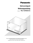
■ Installing the Main Unit
3. Mount the unit into the rack by fixing the rack mounting
screws (locally procured: 8 pcs). (Refer to the following
illustration.)
• Places exposed to direct sunlight or near a source of
heat such as a radiator
• Very dirty and dusty places
• Places subject to strong vibrations
• Near magnetic field sources such as a television or
speakers
• Near high-voltage cables such as a power cable
• Near noise sources such as fluorescent lamps
• Places where condensation forms easily
• Humid places
• Places where drastic temperature changes occur
• Places which are not level
• Steamy and oily places such as kitchens
Rack Mounting
When mounting this unit, use the following racks.
Standard Rack: WU-RS71 (29 units can be mounted.)
Long Rack: WU-RL76 (41 units can be mounted.)
EIA equivalents (Products of other manufacturers): EIA
19 inch rack, 450 mm {17-7/10"} or more depth
Note: When mounting this unit into a rack of another manufacturer, Rack Mounting Screw (W2-MSS/5008) (Option)
or M5 x 12 screws (4 pcs.) are required. If you use the
supplied rack mounting screws (nominal diameter 5
tapping), the screw heads may be damaged.
1. Power off the unit.
2. Remove the rubber feet (4 psc.) on the bottom of the
unit by loosening the screws.
EIA 19 inch rack
Make a space equivalent to
approx. 1 unit (44 mm) or more
Places to avoid
Matrix Switcher WJ-SX
650
Matrix Switcher WJ-SX
650
Important:
• If the rack is subject to vibration, secure the rear of the
unit to the rack by using additional mounting brackets
(locally procured).
• To avoid loosening, secure the mounting screws surely.
• When operating the units, keep the temperature inside
the rack surely below 45 °C {113 °F}.
• Mount the unit into the rack with a space equivalent to
approx. 1 unit (44 mm) or more to separate from other
devices.
• Mounting ventilation fan(s) in the rack is recommended
especially when the rack is covered with front lids.
• To prevent the unit from overheating, do not block the
ventilation openings or slots in the cover
650
Matrix Switcher WJ-SX
Remove the rubber feet.
21
CONNECTIONS
Important:
Use only the recommended BNC connectors listed below.
RECOMMENDED
Tip dimensioins inside the BNC
BNC
Video (coaxial) Cable
fl 1.32 mm — fl 1.37 mm
Tip
(inside)
fl 0.13 mm — fl 0.69 mm
Standards
For U.S.A.
MIL-C39012C or MIL-C39012/16F
For Europe
BS CECC 22120:1981
For Japan
JIS C5412
Suffixes attached to the standards may be updated.
Other BNC connectors may cause video signal interruption, and damage the BNC receptacles on the rear panel of the unit.
22
■ Basic System Connections
The following is a connection example to use one unit.
This unit x 1, camera x 30, monitor x 16, and recorder x 2
Camera 1 to 30
~
~
Monitor 1 to 16
~
CAMERA IN
VIDEO OUT (Loop-thru output)
Video input board
MODE switches
WV-CU950/650
Expansion slot
1 2 3 4 5 6 7 8
MONITOR
OUT
WV-CU360C/CJ
1 2 3 4 5 6 7 8
Terminal mode,
Line termination: ON
Video output board
DATA
MODE switches
DATA
ON
CAMERA IN
1 2 3 4 5 6 7 8
(#7: OFF)
(#8: OFF)
A
SYSTEM CONTROLLER
B
A
B
SYSTEM CONTROLLER
1
4
7
2
3
1
5
6
4
8
9
7
0
2
3
5
6
8
9
0
Recorder
MONITOR OUT
MODE switches
(#7: ON)
(#8: OFF)
ON
CAMERA IN
1 2 3 4 5 6 7 8
SERIAL
Recorder
MONITOR OUT
PC (WJ-SX650 Series
Administrator Console)
23
■ Expanded System Connections
The following is a connection example to use two or more units.
This unit x 3, camera x 150, monitor x 32, and recorder x 10
Camera 1 to 150
CAMERA IN
VIDEO OUT
(Loop-thru output)
~
Video input board
~
CAMERA IN
Card cage connection
Video input board
Monitor 1 to 32
Video input board
MONITOR OUT
~
Video input board
Card cage connection
Video input board
System controller
DATA
Video output board
A
SYSTEM CONTROLLER
Video output board
B
A
SYSTEM CONTROLLER
1
2
3
1
2
3
4
5
6
4
5
6
7
8
9
7
8
9
0
0
SERIAL
DATA
CAMERA
IN
DATA
DATA
CAMERA
IN
Recorder
DATA
Recorder
Recorder
DATA
Recorder
Recorder
Recorder
Recorder
Recorder
Recorder
DATA
Recorder
MONITOR OUT
24
PC (WJ-SX650 Series
Administrator Console)
B
This unit x 4, camera x 240, monitor x 32, and recorder x 15
Camera 1 to 240
CAMERA IN
VIDEO OUT
(Loop-thru output)
~
CAMERA IN
~
Video input board
Card cage connection
Video input board
Monitor 1 to 32
Video input board
MONITOR OUT
~
Video input board
Card cage connection
Video input board
Video input board
System controller
DATA
Video input board
A
SYSTEM CONTROLLER
B
A
B
SYSTEM CONTROLLER
1
4
7
2
3
1
5
6
4
8
9
7
0
2
3
5
6
8
9
0
Card cage connection
PC (WJ-SX650 Series
Administrator Console)
Video input board
Video output board
Video output board
SERIAL
DATA
CAMERA IN
Recorder
DATA
Recorder
DATA
Recorder
DATA
Recorder
Recorder
DATA
Recorder
DATA
Recorder
DATA
Recorder
Recorder
DATA
Recorder
DATA
Recorder
Recorder
DATA
Recorder
DATA
Recorder
DATA
Recorder
25
■ Card Cage Connections
Card Cage WJ-SX650U is used for mounting additional Video Input Board WJ-PB65C32. Up to 3 video input boards can be
mounted into a card cage.
The following is a connection example to use additional card cages.
•
•
•
•
Maximum unit connections: Matrix Switcher WJ-SX650 x 1, Card Cage WJ-SX650U x 3.
Video Output Board 1 and 2 must be mounted into the same unit.
Unit that has video output boards must be at the connection end.
When connecting the EXTENSION 1 to 3 ports of each unit, use Expansion Cable Kit WJ-CA65L20K (Option) or WJCA65L07K (Option).
• Connect nothing to the EXTENSION 1 port of the Video Output Board 2.
4
C
1
2
3
SIGNAL GND
3
EXTENSION 2 IN
EXTENSION 3 IN
RS485 (CAMERA)
MODE
MODE
RS485 (CAMERA)
MODE
IN C-3
MODE
2
VIDEO OUT 3
VIDEO OUT 4
32
31
30
29
VIDEO OUT 1
VIDEO OUT 2
28
27
26
25
24
23
IN X-2
ALARM IN
22
21
20
19
18
RS485(CAMERA) SET UP
17
ON
4-Line
MODE
ON
4-Line
16
15
14
13
12
11
10
9
CAMERA IN
8
7
6
5
4
3
2
1
1
MODE
IN X-1
4
B
1
2
3
3
RS485 (CAMERA)
MODE
MODE
RS485 (CAMERA)
MODE
IN B-3
MODE
2
VIDEO OUT 3
VIDEO OUT 4
VIDEO OUT 1
VIDEO OUT 2
32
31
30
29
28
27
26
16
15
14
13
12
11
10
25
9
CAMERA IN
24
23
8
7
IN X-2
ALARM IN
22
6
21
20
5
4
19
18
3
17
2
1
1
IN X-1
4
3
2
1
OFF
A
ON
AC IN
Line termination: ON at the connection end
3
EXTENSION 3 OUT
MODE
EXTENSION 2 OUT
MODE
DATA (TMNL/HDR)
DATA (TMNL/PS·DATA)
MODE
MODE
OUT
EXTENSION 1 IN
TERM.
IN A-3
2
VIDEO OUT 3
VIDEO OUT 4
VIDEO OUT 1
VIDEO OUT 2
32
31
30
29
28
27
26
16
15
14
13
12
11
10
25
9
CAMERA IN
IN X-2
ALARM IN
24
23
22
21
20
19
18
17
8
7
6
5
4
3
2
1
SIGNAL GND
1
IN X-1
Expansion Cable Kit
WJ-CA65L20K or WJ-CA65L07K
4
C
1
2
3
SIGNAL GND
3
EXTENSION 2 IN
EXTENSION 3 IN
RS485 (CAMERA)
MODE
MODE
RS485 (CAMERA)
MODE
IN C-3
MODE
2
VIDEO OUT 3
VIDEO OUT 4
32
31
30
29
VIDEO OUT 1
VIDEO OUT 2
28
27
26
24
25
23
IN X-2
ALARM IN
22
21
20
19
18
RS485(CAMERA) SET UP
17
ON
4-Line
MODE
ON
4-Line
16
15
14
13
12
11
10
9
CAMERA IN
8
7
6
5
4
3
2
1
1
MODE
IN X-1
4
B
1
2
3
3
RS485 (CAMERA)
MODE
MODE
RS485 (CAMERA)
MODE
IN B-3
MODE
2
VIDEO OUT 3
VIDEO OUT 4
VIDEO OUT 1
VIDEO OUT 2
32
31
30
29
28
27
26
16
15
14
13
12
11
10
25
9
CAMERA IN
24
23
8
7
IN X-2
ALARM IN
22
6
21
20
5
4
19
18
3
17
2
1
1
IN X-1
4
3
2
1
OFF
A
ON
Line termination: OFF
AC IN
3
EXTENSION 3 OUT
MODE
EXTENSION 2 OUT
MODE
DATA (TMNL/HDR)
DATA (TMNL/PS·DATA)
MODE
MODE
OUT
EXTENSION 1 IN
TERM.
IN A-3
2
VIDEO OUT 3
VIDEO OUT 4
VIDEO OUT 1
VIDEO OUT 2
32
31
30
29
28
27
26
16
15
14
13
12
11
10
25
9
CAMERA IN
IN X-2
ALARM IN
24
23
22
21
20
19
18
17
8
7
6
5
4
3
2
1
SIGNAL GND
1
IN X-1
4
2
3
1
C
SIGNAL GND
3
EXTENSION 2 IN
EXTENSION 3 IN
RS485 (CAMERA)
MODE
MODE
RS485 (CAMERA)
MODE
IN C-3
MODE
2
VIDEO OUT 3
VIDEO OUT 4
32
31
30
29
VIDEO OUT 1
VIDEO OUT 2
28
27
26
25
24
23
IN X-2
ALARM IN
22
21
20
19
18
RS485(CAMERA) SET UP
17
ON
4-Line
MODE
ON
4-Line
16
15
DATA 4
14
DATA 3
13
12
DATA 2
DATA 1
Video Output Board 2
HDR4/TMNL8 HDR3/TMNL7
TMNL6
TMNL5
Video Output Board 1
HDR2/TMNL4 HDR1/TMNL3
TMNL2
TMNL1/PS DATA
16
15
14
13
11
12
TERM.OFF
10
ON
9
CAMERA IN
8
6
5
4
3
2
1
1
MODE
IN X-1
4
TERM.ON
7
3
2
1
OFF
B
ON
3
MODE
MODE
11
10
MODE
9
MODE
DATA (TMNL/HDR)
8
7
MODE
DATA (TMNL/PS·DATA)
6
MODE
5
OUT
4
EXTENSION 1 IN
3
TERM.
OUT X-3
2
1
2
OUT X-2
MONITOR OUT
VS IN
1
Video Output Board 1 Only
DATA 3
DATA 2
DATA 1
HDR4/TMNL8 HDR3/TMNL7
TMNL6
TMNL5
Video Output Board 1
HDR2/TMNL4 HDR1/TMNL3
TMNL2
TMNL1/PS DATA
16
15
14
13
VS OUT
(THRU)
ALARM OUT 1
ALARM OUT 2
DATA 4
Video Output Board 2
12
TERM.OFF
ON
4
TERM.ON
VS OUT
3
SERIAL
2
OUT X-1
1
OFF
A
ON
AC IN
Line termination: ON at the connection end
3
MODE
11
MODE
10
MODE
9
DATA (TMNL/HDR)
8
MODE
7
MODE
DATA (TMNL/PS·DATA)
6
MODE
5
4
OUT
EXTENSION 1 IN
3
TERM.
2
OUT X-3
1
2
OUT X-2
MONITOR OUT
VS IN
1
Video Output Board 1 Only
ALARM OUT 2
26
ALARM OUT 1
VS OUT
(THRU)
VS OUT
SERIAL
OUT X-1
SIGNAL GND
■ Camera Connections
The following is a connection example to use system cameras and combination cameras.
Notes:
• Make sure that the cable length is less than 900 m {3 000 ft} between the camera site and the unit when using RG-59/U,
BELDEN 9259 or equivalent cables.
• To display recorded images on monitors connected to this unit, connect the MONITOR OUT connectors of recorders to the
CAMERA IN connectors of the unit.
• When connecting cameras to the unit, reserve more unused connectors than the recorder total number. (Refer to p. 63
Recorder Connections for details.)
32
31
16
19
4
15
18
3
17
2
1
Combination
camera
System camera
4
EXTENSION 2 IN
EXTENSION 3 IN
MODE
VIDEO OUT 3
VIDEO OUT 4
RS485 (CAMERA)
MODE
31
30
29
28
27
26
16
15
14
13
12
11
10
25
9
CAMERA IN
RS485 (CAMERA)
MODE
IN C-3
MODE
VIDEO OUT 1
VIDEO OUT 2
32
1
2
3
IN X-2
ALARM IN
24
23
22
21
20
19
18
17
8
7
6
5
4
3
2
1
IN X-1
Video input rear board
■ RS-485 Camera Connections
There are two options to connect RS-485 cameras to this unit.
• 1:1 connection: One camera is connected to one RS-485 (CAMERA) port.
• Daisy chain connection: Up to 8 cameras can be connected to one RS-485 (CAMERA) port.
Notes:
• Set the line termination to ON for cameras at the connection ends. Line termination setting is performed with the MODE 1 to
4 switches (refer to p. 61) at video input rear boards.
• Perform the RS-485 camera setting in RS485 CAMERA of SETUP MENU (refer to p. 84) or "System" – "RS485 Camera" of
WJ-SX650 Series Administrator Console.
• 1 200 m {3 937 ft} is the total length limit of RS-485 cables.
• Recommended for RS-485 communication is AWG#22 or thicker one. The cable should be shielded, two-wire, twisted pair,
and with low impedance.
• Conform the 2-wire or 4-wire communication setting of this unit to that of RS-485 cameras.
The following is the details on MODE 1 to 4 switch settings.
1
2
3
4
ON
2-wire communication
Line termination: ON
OFF
4-wire communication
Line termination: OFF
4-wire
communication
ON
2-wire
communication
ON
1 2 3 4
1 2 3 4
27
● 1:1 Connection
One camera is connected to one RS-485 (CAMERA) port.
Example: RS-485 cameras are connected to the CAMERA IN 9 and 12 connectors.
4-wire
communication
Connector
2-wire
communication
ON
RS485
(CAMERA) 1
RS485
(CAMERA) 2
ON
1 2 3 4
Junction Unit
WV-CA48/JN
1 2 3 4
(SW#4: ON)
RS-485 cable
(SW#1 to 4: ON)
MODE switch settings
Unit number: 1
Line termination: ON
Unit number: 1
Line termination: ON
4
EXTENSION 2 IN
EXTENSION 3 IN
VIDEO OUT 3
VIDEO OUT 4
RS485 (CAMERA)
MODE
MODE
31
30
29
28
27
26
16
15
14
13
12
11
10
RS485 (CAMERA)
MODE
IN C-3
MODE
VIDEO OUT 1
VIDEO OUT 2
32
1
2
3
25
9
CAMERA IN
IN X-2
ALARM IN
24
23
22
21
20
19
18
17
8
7
6
5
4
3
2
1
IN X-1
Video input rear boards
Note: Do not use unit numbers other than 1 to 8 for individual cameras.
● Daisy Chain Connection
Two or more cameras can be connected to one RS-485 (CAMERA) port. Up to 8 cameras are available.
Example: RS-485 cameras are connected to the CAMERA IN 9 to 12 connectors
4-wire
communication
Connector
Daisy Chain Connection Kit
WV-CA48/10K
ON
RS485
(CAMERA) 1
2-wire
communication
ON
1 2 3 4
Junction Unit
WV-CA48/JN
(SW#4: ON)
1 2 3 4
(SW#1 to 4: ON)
RS-485 cable
MODE switch settings
Unit number: 4
Line termination: ON
Unit number: 3
Line termination: OFF
Unit number: 2
Line termination: OFF
Unit number: 1
Line termination: OFF
4
EXTENSION 2 IN
EXTENSION 3 IN
MODE
VIDEO OUT 3
VIDEO OUT 4
RS485 (CAMERA)
MODE
31
30
29
28
27
26
16
15
14
13
12
11
10
25
9
CAMERA IN
RS485 (CAMERA)
MODE
IN C-3
MODE
VIDEO OUT 1
VIDEO OUT 2
32
1
2
3
IN X-2
ALARM IN
24
23
22
21
20
19
18
17
8
7
6
5
4
3
2
1
IN X-1
Video input rear boards
Notes:
• Among cameras connected to an RS485 (CAMERA) port in the daisy chain (4-wire communication), only one camera can
activate camera alarms.
• Do not use unit numbers other than 1 to 8 for individual cameras.
• Do not set the same unit numbers for more than one camera in an RS-485 chain.
28
■ Monitor Connections
• The MONITOR OUT 1 to 16 connectors of Video Output Board 1 are assigned to Monitor 1 to 16.
• The MONITOR OUT 1 to 16 connectors of Video Output Board 2 are assigned to Monitor 17 to 32.
15
3
16
1
4
DATA 4
DATA 3
DATA 2
DATA 1
Video Output Board 2
HDR4/TMNL8 HDR3/TMNL7
TMNL6
TMNL5
Video Output Board 1
HDR2/TMNL4 HDR1/TMNL3
TMNL2
TMNL1/PS DATA
16
15
14
13
12
TERM.ON
ON
MODE
MODE
11
4
TERM.OFF
10
MODE
9
3
2
2
1
OFF
DATA
MODE
MODE
DATA
MODE
8
7
6
5
4
OUT
EXTENSION 1 IN
3
ON
TERM.
OUT X-3
2
1
OUT X-2
MONITOR OUT
VS IN
Video Output Board 1 Only
VS OUT
(THRU)
ALARM OUT 1
ALARM OUT 2
VS OUT
SERIAL
OUT X-1
Video output rear boards
■ PC Connection
Refer to Serial (RS-232C) Connector Command Reference (PDF file on the supplied CD-ROM) for details on the connection
and communication settings.
PC (WJ-SX650 Series
Administrator Console)
9-pin D-sub
(Female)
DATA 4
DATA 3
DATA 2
DATA 1
Video Output Board 2
HDR4/TMNL8 HDR3/TMNL7
TMNL6
TMNL5
Video Output Board 1
HDR2/TMNL4 HDR1/TMNL3
TMNL2
TMNL1/PS DATA
16
15
14
13
12
TERM.ON
MODE
11
ON
4
TERM.OFF
MODE
10
MODE
9
3
2
1
OFF
DATA
MODE
MODE
DATA
MODE
8
7
6
5
4
OUT
EXTENSION 1 IN
3
TERM.
2
ON
OUT X-3
1
OUT X-2
MONITOR OUT
VS IN
Video Output Board 1 Only
ALARM OUT 2
ALARM OUT 1
VS OUT
(THRU)
VS OUT
SERIAL
OUT X-1
Video output rear boards
29
■ Recorder Connection
The following is a connection example to use recorders.
Note: Use recorders with the following versions.
• WJ-HD300 Series: Ver. 1.61 or later
• WJ-HD300A Series: Ver. 3.10 or later
● Connection to Video Output Connectors of Recorders
To display recorder images on monitors connected to this unit
When the video output connectors of recorders are connected to CAMERA IN connectors of this unit, recorder images can be
displayed on Monitor 1 to 32.
The following is the connection procedure.
1. Assign unit addresses to the recorders. (Refer to p. 67 q.)
Available unit addresses are 1 to 16. The unit address setting must be different from each other.
2. Decide the video input board to supply video input signals from recorder.
Choose a video input board that has more unused connectors (CAMERA IN 17 to 32) than the recorder total number.
Note: Only one video input board can be connected to the video output connector of recorders.
3. Connect the video output connectors (the monitor output 2 connector) of recorders and the CAMERA IN 17 to 32 connectors of the unit.
Recorder's unit address
CAMERA IN channel of
video input board
Recorder's unit address
CAMERA IN channel of
video input board
1
32
9
24
2
31
10
23
3
30
11
22
4
29
12
21
5
28
13
20
6
27
14
19
7
26
15
18
8
25
16
17
Note: To supply video input signals from recorders to video input boards, perform the settings surely in RECORDER of SETUP
MENU (refer to p. 87) or "System" – "Recorder" of WJ-SX650 Series Administrator Console.
30
4
EXTENSION 2 IN
EXTENSION 3 IN
MODE
VIDEO OUT 3
VIDEO OUT 4
RS485 (CAMERA)
MODE
31
30
29
28
27
26
16
15
14
13
12
11
10
25
RS485 (CAMERA)
MODE
IN C-3
MODE
VIDEO OUT 1
VIDEO OUT 2
32
1
2
3
IN X-2
ALARM IN
24
23
22
21
20
19
18
17
8
7
6
5
4
3
2
1
9
CAMERA IN
Video input
board
IN X-1
Up to 16 unused connectors
(CAMERA IN 17 to 32) are required
for recorder connections.
CAMERA IN 17 to 32
Video output
connector
Recorder
Recorder
Recorder
Unit Address (System): 1
Unit Address (System): 2
Unit Address (System): 3
• • • Up to 16 recorders
To display recorder images on external monitors directly connected to recorders
When using all the CAMERA IN connectors of video input boards for camera connections, external monitors can be connected
directly to recorders.
Note: Recorder settings are performed in RECORDER of SETUP MENU (refer to p. 87) or "System" – "Recorder" of WJ-SX650
Series Administrator Console.
● Loop-thru Connection between Camera Input Connectors of Recorders and
VIDEO OUT Ports of this Unit
VIDEO OUT 1 to 4 ports are connected to the camera input connectors of recorders. For connection, use D-sub/BNC Video
Cable WJ-CA68 (Option).
The following is the association of camera input connectors with video output connectors.
Camera input connectors or recorders
Video output connectors (VIDEO OUT 1 to 4) of this unit
1 to 8
VIDEO OUT 1
9 to 16
VIDEO OUT 2
17 to 24
VIDEO OUT 3
25 to 32
VIDEO OUT 4
The following is the association of LCN's and recorder numbers for the loop-thru connections.
LCN
Recorder number (Unit Address (System)
LCN
Recorder number (Unit Address (System)
1 to 16
1
129 to 144
9
17 to 32
2
145 to 160
10
33 to 48
3
161 to 176
11
49 to 64
4
177 to 192
12
65 to 80
5
193 to 208
13
81 to 96
6
209 to 224
14
97 to 112
7
225 to 240
15
113 to 128
8
241 to 256
16
31
Notes:
• When changing connections, perform the LCN settings of camera channels supplying video input signals to recorders. The
LCN settings are performed in "System" – "Recorder" – "Logical Camera Number".
• Camera input signals are looped through the unit. Monitor display information (camera title, etc.) are not recorded.
Video input signals are supplied from
recorders to the CAMERA IN 31 and 32.
4
EXTENSION 2 IN
EXTENSION 3 IN
VIDEO OUT 3
VIDEO OUT 4
RS485 (CAMERA)
MODE
MODE
31
30
29
28
27
26
16
15
14
13
12
11
10
RS485 (CAMERA)
MODE
IN C-3
MODE
VIDEO OUT 1
VIDEO OUT 2
32
1
2
3
25
IN X-2
ALARM IN
24
23
22
21
20
19
18
17
8
7
6
5
4
3
2
1
9
CAMERA IN
Video input
board
IN X-1
D-sub/BNC Video Cable WJ-CA68
32 31 30
25 24
17
16
9
8
1
BNC cable
Recorder
Recorder
LCN: 17 to 32
Unit Address (System): 2
LCN: 1 to 16
Unit Address (System): 1
Do not connect VIDEO OUT of the unit to CAMERA IN of recorders if these
camera channels supply video output signals from recorders.
Note: Do not connect the VIDEO OUT ports of the unit to the CAMERA IN connectors of recorders if these camera channels
supply video output signals from recorders.
● Connection between Recorders and Video Input Boards
By connecting recorders to the DATA ports of this unit, recorder control becomes available from system controllers.
Recorder's unit address (System)
DATA port for recorder connection
1 to 4
DATA 3 port of Video Output Board 1
(Factory default: HDR1)
5 to 8
DATA 4 port of Video Output Board 1
(Factory default: HDR2)
9 to 12
DATA 3 port of Video Output Board 2
(Factory default: HDR3)
13 to 16
DATA 4 port of Video Output Board 2
(Factory default: HDR4)
Note: You can change data port settings according to the connected devices. Setting changes are performed in "System" –
"DATA Port" of WJ-SX650 Series Administrator Console or DATA PORT (refer to p. 90) of SETUP MENU.
32
MODE switch settings
ON
Line termination:
ON
(#2: ON)
1 2
ON
Line termination:
OFF
* The following are abbreviations.
• Unit Address S: Unit Address (System):
• Unit Address C: Unit Address (Controller)
#2: OFF
1 2
Note: Normally, set #2 to ON.
DATA 4
Video Output Board 2
Video Output Board 1
16
DATA 3
HDR4/TMNL8 HDR3/TMNL7
HDR2/TMNL4 HDR1/TMNL3
15
14
DATA 2
DATA 1
TMNL6
TMNL2
TMNL1/PS DATA
13
TERM.ON
ON
4
TERM.OFF
3
2
1
OFF
ON
TMNL5
12
MODE
MODE
11
10
MODE
9
DATA
MODE
MODE
DATA
MODE
8
7
6
5
4
EXTENSION 1 IN
OUT
3
TERM.
OUT X-3
2
1
OUT X-2
MONITOR OUT
Video Output
Board 2
VS IN
Video Output Board 1 Only
DATA 3
DATA 2
DATA 1
Video Output Board 2
HDR4/TMNL8 HDR3/TMNL7
TMNL6
TMNL5
Video Output Board 1
HDR2/TMNL4 HDR1/TMNL3
TMNL2
TMNL1/PS DATA
16
15
14
13
VS OUT
(THRU)
ALARM OUT 1
ALARM OUT 2
DATA 4
12
TERM.ON
MODE
11
ON
4
TERM.OFF
MODE
10
MODE
9
3
VS OUT
SERIAL
2
OUT X-1
1
OFF
DATA
MODE
MODE
DATA
MODE
8
7
6
5
4
EXTENSION 1 IN
OUT
3
ON
TERM.
OUT X-3
2
1
OUT X-2
MONITOR OUT
Video Output
Board 1
VS IN
Video Output Board 1 Only
ALARM OUT 1
ALARM OUT 2
VS OUT
(THRU)
VS OUT
SERIAL
3
Recorder
OUT X-1
1
1
SIGNAL GND
SERIAL
Recorder
4
AUDIO IN
CASCADE
OUT
2
AUDIO OUT
16
15
14
16
15
14
2
MONITOR OUT CASCADE IN
13
12
MODE
2
1
ALARM
COPY 1
POWER
MONITOR (VGA)
11
10
9
ALARM/CONTROL
8
7
DATA
6
5
6
5
RS485(CAMERA)
10/100BASE-T EXT STORAGE
4
3
2
1
IN
AC IN
Unit Address S: 9
Unit Address C: 1
LCN (Logical Camera
Number): 129 to 144
Line termination: OFF
Unit Address S: 5
Unit Address C: 1
Recorder
Unit Address S: 10
Unit Address C: 2
LCN (Logical Camera
Number): 145 to 160
Line termination: OFF
LCN (Logical Camera
Number): 161 to 176
Line termination: OFF
OUT
13
12
11
10
9
VIDEO
8
3
LCN (Logical
Camera Number)
: 81 to 96
Line termination:
OFF
CASCADE
OUT
2
AUDIO OUT
16
15
14
Unit Address S: 12
Unit Address C: 4
LCN (Logical Camera
Number): 177 to 192
Line termination: ON
1
LCN (Logical Camera Number):
1 to 16
Line termination: OFF
SIGNAL GND
16
15
14
2
MONITOR OUT CASCADE IN
12
13
MODE
2
1
ALARM
COPY 1
POWER
MONITOR (VGA)
11
10
9
ALARM/CONTROL
8
7
DATA
6
5
6
5
RS485(CAMERA)
10/100BASE-T EXT STORAGE
4
3
2
1
AC IN
13
12
11
10
9
VIDEO
8
7
4
4
AUDIO IN
3
2
1
LCN (Logical Camera Number):
17 to 32
Line termination: OFF
Recorder
Unit Address S: 2
Unit Address C: 2
1
1
SIGNAL GND
SERIAL
Recorder
2
OUT
3
LCN (Logical
Camera Number)
: 97 to 112
Line termination:
OFF
3
IN
Recorder
Unit Address S: 7
Unit Address C: 3
4
1
1
SERIAL
4
AUDIO IN
Unit Address S: 6
Unit Address C: 2
7
Recorder
Unit Address S: 1
Unit Address C: 1
Recorder
Recorder
Unit Address S: 11
Unit Address C: 3
LCN (Logical
Camera Number)
: 65 to 80
Line termination:
OFF
CASCADE
OUT
2
AUDIO OUT
16
15
14
16
15
14
2
MONITOR OUT CASCADE IN
13
12
MODE
2
1
ALARM
COPY 1
POWER
MONITOR (VGA)
11
10
9
ALARM/CONTROL
8
7
DATA
6
5
6
5
RS485(CAMERA)
10/100BASE-T EXT STORAGE
4
3
2
1
IN
AC IN
OUT
13
12
11
10
9
VIDEO
8
7
4
2
1
LCN (Logical Camera Number):
33 to 48
Line termination: OFF
Recorder
Unit Address S: 3
Unit Address C: 3
Recorder
3
Recorder
Unit Address S: 13
Unit Address C: 1
LCN (Logical Camera
Number): 193 to 208
Line termination: OFF
Unit Address S: 8
Unit Address C: 4
MODE switches
LCN (Logical
Camera Number)
: 113 to 128
Line termination:
ON
ON
(#7: ON)
(#8: OFF)
1 2 3 4 5 6 7 8
3
1
1
SIGNAL GND
Recorder
SERIAL
4
AUDIO IN
CASCADE
OUT
2
AUDIO OUT
16
15
14
16
15
14
2
MONITOR OUT CASCADE IN
12
13
MODE
2
1
ALARM
COPY 1
POWER
MONITOR (VGA)
11
10
9
ALARM/CONTROL
8
7
DATA
6
5
6
5
RS485(CAMERA)
10/100BASE-T EXT STORAGE
4
3
2
1
IN
Unit Address S: 14
Unit Address C: 2
LCN (Logical Camera
Number): 209 to 224
Line termination: OFF
Recorder
Unit Address S: 15
Unit Address C: 3
AC IN
OUT
13
12
11
10
9
VIDEO
Recorder
Unit Address S: 4
Unit Address C: 4
8
7
4
3
2
1
LCN (Logical Camera Number):
49 to 64
Line termination: ON
LCN (Logical Camera
Number): 225 to 240
Line termination: OFF
Recorder
Unit Address S: 16
Unit Address C: 4
LCN (Logical Camera
Number): 241 to 256
Line termination: ON
33
■ Recorder Settings
■ System Controller Connection
Be sure to perform the settings for connected recorders in
SETUP MENU of recorders.
You can set w to t before starting operation. However,
you must set q separately for each recorder before connections. The settings are performed in SETUP MENU
(Advanced).
The following is a connection example to use system controllers.
There are two options to connect system controllers to this
unit.
• Terminal mode: Normally, this operation mode is
applied.
• PS·Data mode: When other system units are connected
to this unit, and they are controlled by the same system
controller, this operation mode is applied. This mode
has operation restrictions. Refer to p. 48 OPERATION
(OTHER THAN TERMINAL MODE.
q Unit Address (System)
Set the Unit Address (System) for each recorder in
"Comm" – "PS.Data Setup". 001 to 016 are available.
(Up to 16 recorders can be connected.) The unit
address setting must be different each other.
w Unit Address (Controller)
Set the Unit Address (Controller) for each recorder in
"Comm" – "PS.Data Setup". 001 to 004 are available.
(Up to 4 recorders can be connected to a DATA port.)
The unit address setting must be different each other.
e Camera Number Setup
Perform the Camera Number Setting for each recorder
in "Comm" – "PS.Data Setup. The camera number settings must be identical as the LCN settings of this unit.
Example: To supply video input signal from Camera 999 to
the CAMERA IN 16 connector of Recorder 16 (Unit
Address (System): 16), select CAM NO. 999 for CAM
PORT 16.
r Camera Control
Select PSD for CAM1 to CAM16 in "Comm" – "Camera
Control".
t Event REC
To activate alarm recording, perform the event recording settings surely. Refer to the operating instructions of
recorders for details.
Maintain the factory default for the following settings.
• PSD User setting in "System" – "Basic Setup": ADMIN
• Operation Mode setting of each Event Program – VMD,
VIDEO LOSS, and Terminal/Command Alarm in
"Schedule" – "Event Program": ALARM
(When setting QUICK for REC Type, Operation Mode
setting of Event REC in "SETUP MENU (Quick)" – "REC
& Event": ALARM)
• Settings in "Comm" – "PS.Data Setup" of SETUP MENU,
except for q to e.
34
● Terminal Mode Connection
To apply the terminal mode, connect the system controllers
as follows.
1. Connect the system controllers to the DATA 1 to 4 ports
of the unit.
Notes:
• In the factory default, the DATA 3 and 4 ports are
set to HDR1 for recorder connection. To connect
system controllers, perform the DATA port settings
in SETUP MENU (refer to p. 90) or WJ-SX650 Series
Administrator Console.
• Both of recorders and system controllers cannot be
connected to the same DATA port.
• By connecting up to 4 system controllers to one
DATA port in the daisy chain, up to 16 system controllers are available in the system. (However, up to
16 system controllers can log into the system at a
time.)
• Daisy chain connection is available with System
Controller WV-CU950/650 (Ver. 2.00 or later).
2. Set the system controllers to the terminal mode. (Refer
to the operating instructions of system controllers.)
3. Set the CONTROLLER NO. switches of system controllers to 1. (In the daisy chain connection, set 1 to 4
for each controller. The switch setting must be different
from each other. However, when connecting system
controllers to different DATA ports, you can use overlapped controller numbers.)
Note: Refer to the operating instructions of system controller for details on the CONTROLLER NO. switch
setting.
ON
Line termination:
ON (#2: ON)
1 2
DATA 4
DATA 3
DATA 2
DATA 1
Video Output Board 2
HDR4/TMNL8 HDR3/TMNL7
TMNL6
TMNL5
Video Output Board 1
HDR2/TMNL4 HDR1/TMNL3
TMNL2
TMNL1/PS DATA
16
15
14
13
12
TERM.ON
ON
MODE
11
4
TERM.OFF
MODE
MODE
10
9
3
2
1
OFF
DATA
MODE
MODE
DATA
MODE
8
7
6
5
4
OUT
EXTENSION 1 IN
3
TERM.
2
ON
OUT X-3
1
OUT X-2
MONITOR OUT
VS IN
Video output
rear boards
Video Output Board 1 Only
VS OUT
(THRU)
ALARM OUT 1
ALARM OUT 2
VS OUT
SERIAL
DATA2
OUT X-1
DATA1
A
SYSTEM CONTROLLER
SYSTEM CONTROLLER
SYSTEM CONTROLLER
SYSTEM CONTROLLER
2
3
1
2
3
1
2
3
1
2
3
1
2
5
6
4
5
6
4
5
6
4
5
6
4
5
6
8
9
7
8
9
7
8
9
7
8
9
7
8
9
7
0
CONTROLLER NO.: 4
Line termination: ON
0
0
CONTROLLER NO.: 2
Line termination: OFF
CONTROLLER NO.: 1
Line termination: OFF
0
CONTROLLER NO.: 3
Line termination: OFF
B
SYSTEM CONTROLLER
1
4
3
0
CONTROLLER NO.: 1
Line termination: ON
Daisy chain connection
● PS·Data Mode Connection
To apply the PS·Data mode, connect the system controllers
as follows.
1. Connect the system controllers to the DATA 1 port of
Video Output Board 1.
Notes:
• In the factory default, the DATA 1 port is set for the terminal mode connection. To apply the PS·Data mode
connection, perform the DATA port settings in SETUP
MENU (refer to p. 90) or WJ-SX650 Series Administrator
Console.
• Both of terminal mode and PS·Data system controllers
cannot be connected to the same DATA port.
• DATA 1 port of Video Output Board 2 cannot be set for
the PS·Data connection.
• Up to 4 system controllers can be connected in the
daisy chain. For system controllers in the daisy chain
connection, operator registration is not available. (The
same operator setting is applied for all the system controllers in the PS·Data daisy chain.)
4. Set the line termination of system controllers with the
MODE switches. (Refer to the operating instructions of
system controllers.) In the daisy chain connection, set
the line termination of chain end system controller to
ON. (Switch #5: ON)
5. In the daisy chain connection, set the CONTROLLER
NO. switches of system controllers to 1 to 4. The switch
setting must be different from each other. (Refer to the
operating instructions of system controller for details on
the CONTROLLER NO. switch setting.)
Note: When using system controllers in the PS·Data
mode, camera numbers that can be selected differ
depending on system controller models.
Example:
WV-CU950/650: 1 to 999
WV-CU360C/CJ: 1 to 199
Select the system controller models that are applicable
for your system composition. When using 200 or more
cameras in the PS·Data mode, apply WV-CU950/650.
2. Set the MODE switch of DATA ports connected to the
system controllers to ON. (Switch #2: ON)
3. Set the system controllers to the PS·Data mode. (Refer
to the operating instructions of system controllers.)
35
■ Alarm Sensor Connections
■ External Device Connections
Alarm input signals can be supplied by alarm sensors connected to the ALARM IN port at the video input board. The
following are the ALARM IN port details.
With external device connections, alarm output, alarm
recover input, time adjust input, and time adjust output signals are supplied and accepted from the ALARM OUT 1
and 2 ports at the video output board. The following are the
ALARM OUT port details.
Note: Perform the setting of each signal polarity and alarm
event in TERMINAL ALARM of SETUP MENU (refer to p.
87) and "Alarm" – "Alarm Event" of WJ-SX650 Series
Administrator Console.
19 18 17 16 15 14 13 12 11 10
9
8
7
6
5
4
3
2
19 18 17 16 15 14 13 12 11 10
9
8
7
6
5
4
3
2
1
1
37 36 35 34 33 32 31 30 29 28 27 26 25 24 23 22 21 20
37 36 35 34 33 32 31 30 29 28 27 26 25 24 23 22 21 20
Pin No.
1
2
3
4
5
6
7
8
9
10
11
12
13
14
15
16
17
18
19
20
21
22
23
24
25
26
27
28
29
30
31
32
33
34
35
36
37
Designation
GND
Alarm Input 1
Alarm Input 2
Alarm Input 3
Alarm Input 4
Alarm Input 5
Alarm Input 6
Alarm Input 7
Alarm Input 8
Alarm Input 9
Alarm Input 10
Alarm Input 11
Alarm Input 12
Alarm Input 13
Alarm Input 14
Alarm Input 15
Alarm Input 16
GND
GND
GND
Alarm Input 17
Alarm Input 18
Alarm Input 19
Alarm Input 20
Alarm Input 21
Alarm Input 22
Alarm Input 23
Alarm Input 24
Alarm Input 25
Alarm Input 26
Alarm Input 27
Alarm Input 28
Alarm Input 29
Alarm Input 30
Alarm Input 31
Alarm Input 32
GND
Alarm Input: 100 or more ms, non-voltage make contact
input
36
Pin
No.
1
2
3
4
5
6
7
8
9
10
11
12
13
14
15
16
17
18
19
20
21
22
23
24
25
26
27
28
29
30
31
32
33
34
35
36
37
ALARM OUT 1
ALARM OUT 2
GND
Alarm Output 1
Alarm Recover Input 1
Alarm Output 2
Alarm Recover Input 2
Alarm Output 3
Alarm Recover Input 3
Alarm Output 4
Alarm Recover Input 4
GND
Alarm Output 5
Alarm Recover Input 5
Alarm Output 6
Alarm Recover Input 6
Alarm Output 7
Alarm Recover Input 7
Alarm Output 8
Alarm Recover Input 8
GND
Alarm Output 9
NC
Alarm Output 10
GND
Alarm Output 11
NC
Alarm Output 12
GND
GND
Alarm Output 13
NC
Alarm Output 14
GND
Alarm Output 15
NC
Alarm Output 16
Time Adjust Output
Time Adjust Input
GND
Alarm Output 17
Alarm Recover Input 9
Alarm Output 18
Alarm Recover Input 10
Alarm Output 19
Alarm Recover Input 11
Alarm Output 20
Alarm Recover Input 12
GND
Alarm Output 21
Alarm Recover Input 13
Alarm Output 22
Alarm Reset Input 14
Alarm Output 23
Alarm Recover Input 15
Alarm Output 24
Alarm Recover Input 16
GND
Alarm Output 25
NC
Alarm Output 26
GND
Alarm Output 27
NC
Alarm Output 28
GND
GND
Alarm Output 29
NC
Alarm Output 30
GND
Alarm Output 31
NC
Alarm Output 32
GND
GND
Terminal
Alarm Output 1 to
32
Duration
Until reset
Remarks
Open Collector
output, 16 V,
100 mA maximum
Alarm Recover
Input 1 to 16
100 or more ms
Non-voltage make
contact output
Time Adjust
Output
1 second
Open Collector
output, 16 V,
100 mA maximum
Time Adjust Input
100 or more ms
Non-voltage make
contact input
Display example of SYSTEM STATUS
<Monitor 1>
LCN, MODE, KB and OPE parameters are highlighted
for monitors during the alarm mode status.
SYSTEM STATUS
MON
LCN
01
02
03
04
05
06
07
08
001
002
200
030
100
MODE
G08
SETUP
HISTORY
KB
OPE
PRI
K1-1
123
PC
K1-4
K3-2
/T001
999
5
10
505
01
03
99
14
00
02
03
R16
LCN:LOGICAL CAMERA NUMBER
■ System Status Check
During connection procedures, system status can be
checked on 4 monitors.
The following examples are procedures to display the system status on Monitor 1 to 4.
● WV-CU950/650
1. Select one of Monitor 1 to 4. (Refer to p. 21 Monitor
Selection.)
LCN and MODE parameters are highlighted for monitors
during the alarm ACK status.
<Monitor 4>
SYSTEM STATUS
MON
LCN
MODE
25
26
27
28
29
30
31
32
075
105
002
301
401
501
999
T32
T01
G32
G32
G32
KB
OPE
PSD
48
/T128
3
12345
12345
12345
K6-3
K8-4
PRI
02
60
05
10
10
10
LCN:LOGICAL CAMERA NUMBER
2. Press the MENU button repeatedly until "System Status"
appears on the LCD.
3. Press the F1 button. SYSTEM STATUS will be displayed
on Monitor 1 to 4.
Note: SYSTEM STATUS is displayed on a set of 4 monitors
(Monitor 5 to 8, Monitor 9 to 12...Monitor 29 to 32).
● WV-CU360C/CJ
1. Select one of Monitor 1 to 4. (Refer to p. 21 Monitor
Selection.)
2. Press the OSD and SYS S buttons at a time. SYSTEM
STATUS will be displayed on Monitor 1 to 4.
Note: SYSTEM STATUS is displayed on a set of 4 monitors
(Monitor 5 to 8, Monitor 9 to 12...Monitor 29 to 32).
MON: Monitor number
LCN: Camera number or recorder number
MODE: Display mode of the monitor
• SETUP: System Setup
• HISTORY: Alarm History Display
KB: System controller or PC
OPE: User ID of the operator or timer event No.
PRI: Operator priority
• When SETUP MENU is displayed, "0" appears on
this area.
• During monitor lock, this area is highlighted.
Notes:
• Even while SYSTEM STATUS is being displayed on
monitors, normal operations and alarm control are available. However, you cannot check the camera or recorded images because black screen is displayed. It is recommended to use these monitors only to check SYSTEM STATUS.
• Up to 100 records of SYSTEM STATUS are saved in the
system. These records can be transmitted between PC
and this unit. (Periodical transmission is also available.)
For transmission, perform the serial command settings
in "Communication" – "Serial Command" of WJ-SX650
Series Administrator Console.
• To transmit SYSTEM STATUS records from the PC, refer
to Serial (RS-232C) Connector Command Reference
(PDF file on the supplied CD-ROM).
37
SETUP PROCEDURE
Before operation, setup of this unit is required. Setup is performed from WJ-SX650 Series Administrator Console
installed on a PC. (Some settings are available from SETUP
MENU of this unit.) The following is an example of setup
procedure.
<WJ-SX650 Series Administrator Console>
"System" – "DATA Port"
Notes:
• Setup may differ depending on system composition.
(Settings of Step 1 and 4 in the following procedure
must be performed.)
• For Step 2, 3, 5 and 6 in the following setup procedure,
the factory default can be maintained.
<WJ-SX650 Series Administrator Console>
"System" – "VD2/DATA/Cable Comp."
<SETUP MENU>
DATA PORT (Refer to p. 90.)
Example: camera x 150, recorder x 10, monitor x 32, and
system controller x 2 (Terminal mode)
1. Perform the recorder settings.
Recorder Out: Input Board No.5 (When video input signals are supplied from recorders to CAM160 to 151)
Recorder 1 to 10: ON
Recorder 11 to 16: OFF
Note: Check if recorders are properly connected to the
DATA port and CAM (camera input channels) currently
displayed.
<WJ-SX650 Series Administrator Console>
"System" – "Recorder"
<SETUP MENU>
VD2/DATA/CABLE COMPENSATION (Refer to p. 91.)
3. Perform the LCN (Logical Camera Number) settings.
CAM001 to 160: If you change LCN settings, select
desired parameters.
CAM161 to 256: Delete the LCN parameters.
Notes:
• Set LCN parameters for CAM151 to 160 surely, even
though these channels accept video input signals from
recorders. Without LCN settings, recorder selection is
unavailable.
• By deleting the LCN parameters of unused camera
channels, operators can select only existing camera
numbers.
<WJ-SX650 Series Administrator Console>
"System" – "Logical Camera Number"
<SETUP MENU>
RECORDER (Refer to p. 87.)
2. Perform the DATA port settings. (In this example, maintain the factory default.)
DATA 1, 2, 5 and 6 ports: TMNL
DATA 3, 4, 7 and 8 ports: HDR
Note: Change these parameters when using PS·Data
system controllers, etc.
38
<SETUP MENU>
Not available
4. Perform the camera settings.
CAM001 to 150: Select desired parameters for these
cameras. (To use cameras of other manufacturers,
set DATA to OFF.) For Cable (cable compensation),
select the parameter suited to the cable length.
CAM151 to 160: Set DATA to OFF. (Video input signals
are supplied from recorders to these channels.)
5. Perform the RS-485 camera settings.
CAM001 to 150: If you use RS-485 cameras, select
desired parameters for the RS-485 ports and camera unit numbers.
<WJ-SX650 Series Administrator Console>
"System" – "RS485 Camera"
<SETUP MENU>
RS485 CAMERA (Refer to p. 92.)
6. Perform the settings of cameras supplying video input
signal to recorders.
<Recorder 1 to 10>
LCN Setting (CAM 1 to 16): LCN settings for cameras
supplying loop-thru video output signal to
recorders. (In this example, maintain the factory
default.)
Note: Change these parameters when you have
changed the LCN settings in Step 3 or loop-thru
connections. (Refer to p. 65.)
<WJ-SX650 Series Administrator Console>
"System" – "Recorder"
<SETUP MENU>
Not available
7. Perform the camera title settings.
CAM001 to 160: Enter desired camera titles.
<WJ-SX650 Series Administrator Console>
"System" – "Camera Title"
<SETUP MENU>
Not available
8. Set the current time and date.
<WJ-SX650 Series Administrator Console>
"Display" – "Display"
<SETUP MENU>
TIME&DATE (Refer to p. 85.)
39
WJ-SX650 SERIES ADMINISTRATOR CONSOLE
This chapter explains about WJ-SX650 Series Administrator
Console. Before controlling WJ-SX650 Series Administrator
Console, installation on the PC is required.
■ Installation and Uninstallation
● Installation
1. Insert the supplied CD-ROM into the CD-ROM drive on
the PC.
■ System Requirements of a PC
To install WJ-SX650 Series Administrator Console, the PC
should meet the following requirements.
OS:
One of the following operating systems:
Microsoft® Windows® 2000 Professional SP4
Microsoft® Windows® XP Professional SP2
Microsoft® Windows® XP Home Edition SP2
Note: To work WJ-SX650 Series Administrator Console on
the PC, Microsoft® .NET Framework 1.1 needs to be
installed.
If you try to install WJ-SX650 Series Administrator
Console on a PC without Microsoft® .NET Framework
1.1, it will be installed along with the console.
PC:
IBM PC/AT Compatible
CPU:
Intel® Pentium® 3, 500 MHz or faster
Memory:
128 MB or more
CD-ROM drive:
Required for installation of WJ-SX650 Series Administrator
Console
Hard drive space:
30 MB or more for installation of WJ-SX650 Series
Administrator Console
Note: If Microsoft® .NET Framework 1.1 has not been
installed on the PC, 160 MB or more is required.
Monitor:
1 024 x 768 pixels or more, HIGH color 16 bit or more
Serial Interface:
9-pin D-sub connector
40
2. Double-click "Setup.exe" in the "Admin" folder of CDROM.
The installation wizard will be displayed on the PC
screen.
3. Click "OK", and follow the directions.
Note: In the factory default installation, C:\Program
Files\Panasonic\WJ-SX650 is created, and files will be
copied to the directory.
● Uninstallation
1. Select "Start" – "All Programs" – "Control Panel" –
"Add/Remove Programs".
"Add/Remove Programs" window will be displayed on
the PC screen.
2. Select "WJ-SX650 Series Administrator Console".
3. Click "Remove" or "Change/Remove", and follow the
directions.
Note: If WJ-SX650 Series Administrator Console has
already been installed on a PC, installation is impossible. Install the application again after uninstallation.
■ Starting Up
■ Window Details
!2
1. Select "Start" – "All Programs" – "Panasonic" – "WJSX650 Series" – "WJ-SX650 Series Administrator
Console x.xx". (x.xx is the version number.) Then, run
the program.
WJ-SX650 Series Administrator Console will start up,
and the login window will be displayed on the PC
screen.
2. Enter the user name and password. The factory default
is as follows.
User Name: admin
Password: sx650
3. Click "OK". "WJ-SX650 Series Administrator Console"
window is displayed.
!1
● Tool Bar
4. To download setting data from the unit, click on the icon
pointed in the illustration. "Download" window will be
displayed.
5. Click on "Start Download". The setting data will be
downloaded from the unit to the PC.
Note: Refer to p. 62 PC Connection for how to connect
the unit and PC.
6. When download is complete, a message window is displayed. Then, click "OK". "System" – "Logical Camera
Number" is displayed.
Note: If you upload the setting data from the PC to the
unit while SETUP MENU is open on a monitor,
SETUP MENU will be closed forcibly. Settings performed in SETUP MENU will be cancelled (cancelled) and replaced by those uploaded from the
PC.
q
: Downloads the current setup data of the unit to
the PC.
w
: Uploads the setup data (configured in WJ-SX650
Series Administrator Console) from the PC to the
unit.
e
: Creates the initial settings.
r
: Opens the file in which the setup data was saved.
t
: Saves the setup data as a file.
y
: Opens the settings guidance window.
u
: Displays the information of video input board/output board.
i
: Displays the user settings page.
o
: Displays the settings page of SERIAL port.
!0
: Displays the version
Administrator Console.
of
WJ-SX650
Series
!1 These buttons are clicked when setting categories are
selected.
!2 Selects a tab screen.
Setting menu and tab screen names are shown as follows.
"Setting menu" – "Tab screen"
!3 Setting details are displayed when !1 and !2 are
clicked.
!4
: Determines the settings.
!5
: Clears the settings.
41
Note: Do not edit the setup data files by using text editors,
etc. You may become unable to open the setup data
files.
■ Tooltip Details
When you point the cursor on a button or pull-down menu,
a tooltip appears. Tool tips that have additional explanations include reference numbers such as "∗1". Refer to the
following diagram for these additional explanations.
42
Reference No.
Explanation
1
1 to 8: Port No.
2
4800 bps, 9600 bps, 19200 bps, 38400 bps: Transmission speed
3
Character entry limit: 20 characters Available characters: Alphanumeric characters and symbols
4
1,2: Level
5
1 to 8: Video input board No.
6
Available parameters: Blank, 1 to 999
7
ON: Use
OFF: Not use
Note: ON is not available for recorders when camera input channels are set for RS-485 cameras. To activate recorder connections, set "--" for DATA Port and Address in "System" – "RS485 Camera".
8
Available parameters: Blank, 1 to 999
Note: Select the camera numbers that has been set in "System" – "Logical Camera Number".
9
[DATA1] TMNL1, PSD: Port type
[DATA1] TMNL2: Port type
[DATA3] TMNL3, HDR1: Port type
[DATA4] TMNL4, HDR 2: Port type
[DATA5] TMNL 5: Port type
[DATA6] TMNL 6: Port type
[DATA7] TMNL7, HDR3: Port type
[DATA8] TMNL8, HDR4: Port type
10
4800 bps, 9600 bps, 19200 bps: Transmission speed
To change the transmission speed, conform the settings of this unit to that of connected devices.
11
[Input Board 1] 1 to 4: Port number
[Input Board 2] 5 to 8: Port number
[Input Board 3] 9 to 12: Port number
[Input Board 4] 13 to 16: Port number
[Input Board 5] 17 to 20: Port number
[Input Board 6] 21 to 24: Port number
[Input Board 7] 25 to 28: Port number
[Input Board 8] 29 to 32: Port number
Note: Port numbers cannot be set for camera channels accepting video input signals from recorders. To
activate RS-485 camera connections, change the settings in "System" – "Recorder".
12
1 to 8: Camera unit number
Note: Camera unit address cannot be set for camera channels accepting video input signals from
recorders. To activate RS-485 camera connections, change the settings in "System" – "Recorder".
13
ON: Overlap
OFF: Not overlap
14
S: Less than 400 m {1 300 ft}
M: 400 m {1 300 ft} to 700 m {2 300 ft}
L: 700 m {2 300 ft} to 900 m {3 000 ft}
Note: Refer to p. 61 for details on the cable length.
Reference No.
Explanation
15
2005 to 2099: Year
16
1 to 12: Month
17
1 to 31: Day
18
[24-h time format] 0 to 23: Time
[12-h time format] 1 to 12: Time
19
00 to 59: Minute
20
AM, PM: Morning, Afternoon
21
DD/MM/YYYY, MM/DD/YYYY, YYYY/MM/DDDD, DD/Mmm/YYYY, Mmm/DD/YYYY: Date Format
22
Japanese, English, French*, Spanish*, German*, Italian*, and Russian*: Language
* In the actual display, these parameters are displayed in their own languages.
23
[24-h] 0:00 to 23:00: Start Time
[12-h] 1:00 AM to 12:00 PM: Start Time
24
Date
25
Way to press keys
A to Z: Click each key while holding down the SHIFT key.
a to z: Click each key.
0 to 9: Click each key.
26
1 to 32: Page
27
Available parameters: 1 to 9999
28
Available parameters: 1 to 999
Note: You can select logical camera numbers that have been set in "System" – "Logical Camera Number".
29
Available parameters: 1 to 256
30
1 to 32: Tour sequence No.
31
Available parameters: 1 to 9999
Note: You can select camera position numbers that have set in "Camera" – "Camera Position".
32
Available parameters: Blank, 1 to 256
33
ON: Activate, OFF: Not activate, --: Not control
34
1 to 30 sec: Dwell
35
1 to 32: Group Sequence No.
36
1 to 32: Monitor No.
37
1 to 99: Priority
38
1 to 30 sec: Dwell Time
39
OFF: Auto reset is OFF.
1 to 10 sec, 20 sec, 30 sec, 1 min, 3 min, 5 min: Alarms are reset after this period.
40
N.O.: Normally Open contact
N.C.: Normally Close contact
41
1 to 256: Terminal Alarm
1 to 999: Camera Alarm, Recorder Alarm, Video Loss
Note: You can select camera numbers that have set in "System" – "Logical Camera Number".
1 to 1024: Serial Alarm
42
When Display Mode is set to SPOT, up to 8 events can be added.
43
1 to 64: Alarm schedule No.
Note: You can select only registered schedules.
OFF: Always Active
44
SPOT: Displays a spot camera image
T-SEQ1 to 32: Activates Tour Sequence 1 to 32.
G-SEQ1 to 32: Activates Group Sequence/Preset 1 to 32.
Note: You can select available events only.
45
1 to 999: Recording Source (LCN)
When an alarm event occurs, a command alarm specifying the LCN of recording source camera is transmitted to the recorder.
Note: Recording follows the settings of command alarm and event recording. Refer to the operating instructions of recorders.
43
Reference No.
Explanation
46
1 to 1024: Alarm Output number
Alarm output signal is supplied from the ALARM OUT 1/2 port or the SERIAL port. (65 to 1024 are supplied
from the SERIAL port only as a serial command.)
Note: To activate serial command transmission, set Alarm Output to ON in "Communication" – "Serial
Command".
Spot: Only the spot images can be activated for the alarm event.
Tour Sequence: Only tour sequences can be activated for the alarm event.
Group Sequence: Only group sequences can be activated for the alarm event.
Note: You cannot change the Display Mode if an alarm event has been associated with the monitor. To
change the setting, you need to delete the alarm event setting or change the monitor setting for the
alarm event.
Available digits: 5 or less
Available numerics: 0 to 9
Notes:
• Begin the entry with a numeric other than "0".
• 99999 is not available.
47
48
44
49
Available digits: 5 or less
Available numerics: 0 to 9
Note: Begin the entry with a numeric other than "0".
50
1 to 5: Level
51
View & Operate: An operator can display the selected camera image on the selected monitor. The operator
can also control the camera.
View: An operator can display the selected camera image on the selected monitor, but cannot control the
camera.
--: The operator can neither display the selected camera image on the selected monitor nor control the
camera.
52
User ID: Select a registered User ID.
53
1, 3, 5, 10, 30, or 60 min: If no operations are performed during this period in the login status, the operator
logs out of the system automatically.
54
1 to 2: Video output board No.
55
Available parameters: 1 to 4096
56
OFF: Alarm occurrence is not notified.
0 sec: Every time alarm occurrence is detected, system controllers are notified.
1 sec, 3 sec, 5 sec: 1 second, 3 second, or 5 seconds after the alarm occurrence, system controllers are
notified.
57
OFF: Alarm notification is not retried.
100 ms, 200 ms, 400 ms, 1 sec: Period until alarm notification is retried
58
0 to 16: Total recorder number
Note: When camera input channels to supply video input signals from recorders are set to "RS485" in
"System" – "RS485 Camera", the RS485 settings are automatically cancelled.
59
0 to 1: Total number of PS·Data system controllers
60
ON, OFF, AUTO, _: B/W setting
61
PATROL1(S) to PATROL4(S) , _: Patrol picture quality
62
ON: Perform
OFF: Not perform
Note: Depending on the specifications of recorders, recording may be stopped for several seconds at the
timing of auto time adjustment.
63
ON: Perform
OFF: Not to perform
Note: To perform auto time adjustment, check the specifications of connected device before the setting.
64
OFF: Not notify
1, 5, 10, 30 or 60 sec
Select the interval to notify the system status. (Recommended: 5 or more sec)
■ Factory Default Settings of WJSX650 Series Administrator
Console
In the factory default, each setting item has been set as follows. Items attached with "*" can also be set in SETUP
MENU.
● System
LCN
1
1
•
•
•
•
256
256
"Display"
Date Format: Mmm/DD/YYYY (For U.S., Canadian and
Puerto Rican fields)
DD/MM/YYYY (For the other fields)
Time Format: 12-h (For U.S., Canadian and Puerto Rican
fields)
24-h (For the other fields)
Language: English*
"DST/Summer Time"
Summer Time: ON*
Start Time: 02:00 AM (For U.S., Canadian and Puerto Rican
fields)
02:00 (For the other fields)
DST/Summer Time Table: The first Sunday in April to the
last Sunday in October (For U.S., Canadian and Puerto
Rican fields)
The last Sunday in March to the last Sunday in October
(For the other fields)
"Logical Camera Number"
CAM
● Display
"Recorder"
Recorder Out: External Monitor
● Camera
Recorder
Control
CAM
LCN Setting
1
ON*
257
1 to 16
2
ON*
258
17 to 32
•
•
•
•
CAM
Camera title
•
•
•
•
1
1
16
ON*
272
241 to 256
•
•
•
•
256
256
"DATA Port"
"Camera Title"
DATA
Type
Communication Status
1
TMNL1*
9 600 bps
2
TMNL2*
9 600 bps
3
HDR1*
9 600 bps
4
HDR2*
9 600 bps
CAM-P
LCN
5
TMNL5*
9 600 bps
1 to 64
LCN 1 (Preset 1 to 64)
6
TMNL6*
9 600 bps
65 to 128
LCN 2 (Preset 1 to 64)
7
HDR3*
9 600 bps
129 to 192
LCN 3 (Preset 1 to 64)
8
HDR4*
9 600 bps
193 to 256
LCN 4 (Preset 1 to 64)
"RS485 Camera"
No setting
RS485: Commuinication Status
1 to 32: 19 200 bps
Custom Chars: A to Z, a to f
"Camera Position"
● Sequence
"VD2/DATA/Cable Comp."
CAM
VD2
DATA
Cable.
1 to 256
ON*
ON*
S*
"Tour Sequence"
Tour Sequence 1: Images of LCN 1 to 32 are sequentially
switched for two seconds.
Tour Sequence 2: Images of LCN 33 to 64 are sequentially
switched for two seconds.
Tour Sequence 3: Images of LCN 65 to 96 are sequentially
switched for two seconds.
Tour Sequence 4: Images of LCN 97 to 128 are sequentially
switched for two seconds.
Tour Sequence 5: Images of LCN 129 to 160 are sequentially switched for two seconds.
Tour Sequence 6: Images of LCN 161 to 192 are sequentially switched for two seconds.
45
Tour Sequence 7: Images of LCN 193 to 224 are sequentially switched for two seconds.
Tour Sequence 8: Images of LCN 225 to 256 are sequentially switched for two seconds.
Tour Sequence 9 to 32: No settings
Terminal Alarm: ON (All alarms are N.O.)*
Camera Alarm: OFF*
Recorder Alarm: OFF*
Serial Alarm: OFF*
Video Loss: OFF*
"Group Sequence"
Group Sequence 1: 4 cameras among LCN 1 to 64 are
sequentially switched for 2 seconds on Monitor 1 to 4.
Group Sequence 2: 4 cameras among LCN 65 to 128 are
sequentially switched for 2 seconds on Monitor 5 to 8.
Group Sequence 3: 8 cameras among LCN129 to 256 are
sequentially switched for 2 seconds on Monitor 9 to 16.
Group Sequence 4 to 8: No settings
Group Sequence 9: Spot image of LCN 1 to 16 are displayed on Monitor 1 to 16.
Group Sequence 10 to 32: No settings
"Alarm Event"
Terminal Alarm 1 to 256: SPOT, LCN 1 to 256, Monitor 1
Camera Alarm 1 to 256: No settings
Recorder Alarm 1 to 256: No settings
Video Loss 1 to 256: Monitor 4 (No events)
Serial Alarm 1 to 1024: No settings
● Schedule
"Timer Event"
No settings
"Monitor Display Mode"
Monitor
Display Mode
1 to 16
Spot
17 to 24
Tour Sequence
25 to 32
Group Sequence
"Alarm Schedule"
No settings
"Camera Event"
No settings
● Operator
"Operator"
Note: Refer to p. 19 Operator Registration.
● Alarm
"Alarm Mode"
Alarm Mode: Sequence* (Dwell Time: 2 sec*)
Auto Reset: 30 sec*
PS·Data: User ID: 650
HDR Network Operation: Priority: 1
"Level Table"
46
Item
Level 1
Level 2
Level 3
Level 4
Level 5
System
Enabled
(Checked)
Disabled
(Not checked)
Disabled
Disabled
Disabled
OSD Control
Enabled
Enabled
Disabled
Disabled
Disabled
Alarm History Display
Enabled
Enabled
Disabled
Disabled
Disabled
System Status Display
Enabled
Disabled
Disabled
Disabled
Disabled
Alarm Suspension
Enabled
Disabled
Disabled
Disabled
Disabled
Alarm All reset reset
Enabled
Enabled
Disabled
Disabled
Disabled
Alarm ACK, Alarm Individual/
Monitor Reset
Enabled
Enabled
Enabled
Disabled
Disabled
Start Tour Sequence
Enabled
Enabled
Enabled
Enabled
Disabled
Start Group Sequence
Enabled
Enabled
Enabled
Enabled
Disabled
Monitor Lock
Enabled
Enabled
Disabled
Disabled
Disabled
Camera Setup
Enabled
Disabled
Disabled
Disabled
Disabled
Preset Position Registration
Enabled
Enabled
Disabled
Disabled
Disabled
All Cameras Control
Enabled
Enabled
Disabled
Disabled
Disabled
Camera Control
Enabled
Enabled
Enabled
Disabled
Disabled
Camera Selection
Enabled
Enabled
Enabled
Enabled
Disabled
Recorder Setup
Enabled
Disabled
Disabled
Disabled
Disabled
Recorder Control
Enabled
Enabled
Enabled
Disabled
Disabled
● Controller
"Monitor Access"
DATA
Monitor
1 to 8
All the ports are enabled.
(Checked)
"Auto Login/Logout"
Auto Login: All the ports are enabled. (Checked) (User ID:
650)
Auto Logout: All the ports are unabled. (Not Checked)
"Key Assignment" (Available for WV-CU950/650)
DATA 1 to 8
Function
A
Iris Reset
B
Auto Focus
TOP
Auto Focus
● Communication
"Serial Command"
Alarm Notification: OFF
System Status Notification: OFF
Alarm Output: OFF
"PS.Data"
Unit Address: 1
<Communication Status>
Retry Timing: OFF
<Auto Time Adjustment>
Recorder (HDR) port: OFF
Whole PS.Data System (PSD port): OFF
Adjustment time: 14:00 (or 02:00 PM)
● SETUP MENU
"SYSTEM" Menu
Communication speed of SERIAL port: 38 400 bps
47
SETUP MENU (OSD)
This chapter explains about SETUP MENU (On-screen
Display setup menu) of this unit.
● Top Menu
When SETUP MENU is opened, the top menu is displayed
on the monitor.
■ Basic Operations
To control SETUP MENU, display SETUP MENU on a monitor.
● WV-CU950/650
1. Select a desired monitor. (Refer to p. 21 Monitor
Selection.)
WJ-SX650 SETUP MENU
100 TIME&DATEO
300 ALARMO
400 RECORDERO
500 SYSTEMO
800 INFORMATIONO
900 LANGUAGE
ENGLISH
2. Press the MENU button repeatedly until "System Setup"
appears on the LCD.
3. Press the F1 button. SETUP MENU will be displayed on
the selected monitor.
● WV-CU360C/CJ
1. Select a desired monitor. (Refer to p. 21 Monitor
Selection.)
2. Press the SETUP button while holding down the SHIFT
button.
SETUP MENU will be displayed on the selected monitor.
Moves the cursor: Move the joystick. The cursor is highlighted when you point.
Moves to the next/previous page (When the displayed menu
has two or more pages): Move the cursor to the top or
bottom. The next or previous page will be displayed on
the monitor.
Note: When using WV-CU950/650, you can perform this
operation by rotating the shuttle ring or moving the
zoom wheel controller.
Changes the selected parameter: Rotate the JogDial, or
press the + or – button.
Enter the numeric parameter: Press the numeric buttons. To
clear the numeric entry, press the CLEAR button.
Moves to the lower menu: Move the cursor to a setting item
which has an arrow mark, and then press the CAM
(SET) button.
Moves to the upper menu: Press the MON (ESC) button.
Exits the SETUP MENU: When using WV-CU950/650, press
the F2 button. When using WV-CU360C/CJ, press the
SETUP button while holding down the SHIFT button.
Notes:
• Sequence is stopped on monitors displaying SETUP
MENU.
• Alarms are not activated on monitors displaying SETUP
MENU.
48
■ TIME & DATE
■ ALARM
You will set the current time and date.
When you select TIME & DATE on the top menu, the following menu is displayed.
Note: Display format setting is performed in "Display" –
"Display" of WJ-SX650 Series Administrator Console.
You will perform the settings of alarms (terminal alarms,
camera alarms, recorder alarms, serial alarms, and video
loss).
When you select ALARM on the top menu, the following
menu is displayed.
300 ALARM
100 TIME&DATE
Aug/31/2005 ∗08:15 PM
DST/SUMMER TIME
ON
310 ALARM MODE
B DWELL TIME
320 AUTO RESET
SEQUENCE
2sec
OFF
330
340
350
360
370
ONO
OFF
OFF
ON
ON
TERMINAL ALARM
CAMERA ALARM
RECORDER ALARM
SERIAL ALARM
VIDEO LOSS
• Year
2005 to 2099
• Month
1 to 12 (When Date Format is set to DD/MM/YYYY,
MM/DD/YYYY, YYYY/MM/DDDD in WJ-SX650 Series
Administrator Console)
Jan, Feb, Mar, Apr, May, Jun, Jul, Aug, Sep, Oct, Nov, Dec
(When Date Format is set to DD/Mmm/YYYY or
Mmm/DD/YYYY in WJ-SX650 Series Administrator Console)
• Day
1 to 31
• Time
● ALARM Menu
• ALARM MODE
Select the display pattern to display spot alarm pictures on
the associated monitors. (The factory default is
SEQUENCE.)
SEQUENCE: Alarm pictures are sequentially displayed on
the associated monitor. Select desired DWELL TIME
from 1 to 30 sec. (The factory default is 2 sec.)
LATEST: The latest alarm picture is displayed on the monitor.
EARLIEST: The earliest alarm picture is displayed on the
monitor.
0 to 23(When Time Format is set to 24-h in WJ-SX650
Series Administrator Console)
1 to 12(When Time Format is set to 12-h in WJ-SX650
Series Administrator Console)
AM /PM (When Time Format is set to 12-h in WJ-SX650
Series Administrator Console)
• AUTO RESET
• Minute
• TERMINAL ALARM
0 to 59
Select ON or OFF to accept or not accept terminal alarm
input signals.
ON: Accepts terminal alarm input signals.
OFF: Not accepts terminal alarm input signals.
• DST/SUMMER TIME
ON/OFF
The factory default is as follows.
Jan/01/2005 00:00AM, DST/SUMMER TIME ON
Note: When DST/SUMMER TIME is set to ON, the daylight
saving time (summer time) is activated during the specified period. ("∗" is displayed beside the time.) The period setting is performed in "Display" – "DST/Summer
Time" of WJ-SX650 Series Administrator Console.
Select the period until an alarm is automatically reset. If you
select OFF, you will reset the alarm manually. (The factory
default is 30 sec.)
OFF/1, 2... to 10 sec/20 sec/30 sec/1 min/3 min/5 min
Note: If you select ON, you can move to TERMINAL
ALARM (refer to p. 85), and you can set the details on
terminal alarm input signal.
• CAMERA ALARM
Select ON or OFF to accept or not accept camera alarm
input signals.
ON: Accepts camera alarm input signals.
OFF: Not accepts camera alarm input signals.
49
• RECORDER ALARM
Select ON or OFF to accept or not accept recorder alarm
input signals.
ON: Accepts recorder alarm input signals.
OFF: Not accepts recorder alarm input signals.
• SERIAL ALARM
Select ON or OFF to accept or not accept serial alarm input
signals.
ON: Accepts serial alarm input signals.
OFF: Not accepts serial alarm input signals.
■ RECORDER
You will check the settings of DATA ports to connect
recorders and CAMERA IN connectors to supply video
input signals from recorders. When you select RECORDER
on the top menu, the following menu is displayed.
Note: Before the settings, check the system composition
and refer to p. 63 Recorder Connection.
400 RECORDER
1 of 2
RECORDER OUT
INPUT BOARD8
RECORDER
DATA
CAM
01
HDR1
256
ON
02
HDR1
255
ON
03
HDR1
254
ON
04
HDR1
253
ON
05
HDR2
252
ON
06
HDR2
251
ON
07
HDR2
250
ON
08
HDR2
249
ON
• VIDEO LOSS
Select ON or OFF to accept or not accept video loss input
signals.
ON: Accepts video loss input signals.
OFF: Not accepts video loss input signals.
DATA=DATA(TMNL/PSD/HDR)
CAM=CAMERA IN
● TERMINAL ALARM Menu
330 TERMINAL ALARM
INPUT BOARD=8
ALM
ALM
233 N.C.
225 N.O.
226 N.O.
234 N.C.
227 N.O.
235 N.C.
228 N.O.
236 N.C.
229 N.O.
237 N.C.
230 N.O.
238 N.C.
231 N.O.
239 N.C.
232 N.O.
240 N.C.
ALM=ALARM IN
ALM
241
242
243
244
245
246
247
248
N.O.
N.O.
N.O.
N.O.
N.O.
N.O.
N.O.
N.O.
ALM
249
250
251
252
253
254
255
256
400 RECORDER
2 of 2
RECORDER OUT
INPUT BOARD8
RECORDER
DATA
CAM
09
HDR3
248
ON
10
HDR3
247
ON
11
HDR3
246
ON
12
HDR3
245
ON
13
HDR4
244
ON
14
HDR4
243
ON
15
HDR4
OFF
16
HDR4
0FF
N.C.
N.C.
N.C.
N.C.
N.C.
N.C.
N.C.
N.C.
DATA=DATA(TMNL/PSD/HDR)
CAM=CAMERA IN
N.O.:NORMALLY OPEN
N.C.:NORMALLY CLOSE
• INPUT BOARD
Select a video input board from 1 to 8. (The factory default
is 1.
• ALM
Select the alarm contact type for each terminal alarm input
signal. (The factory default is N.O.)
N.O.: Normally Open contact
N.C.: Normally Close contact
• RECORDER OUT
Select the video input board or external monitor to supply
video input signals from recorders.
Refer to p. 63 for connections.
INPUT BOARD1 to 8: Recorder images are displayed on
monitors connected to the unit.
EXTERNAL INPUT: Recorder images are displayed on
external monitors directly connected to recorders.
• RECORDER
Select the desired recorder. 1 to 16 are the recorder unit
addresses. (The factory default is ON.)
ON: The recorder is used.
OFF: The recorder is not used.
• DATA
DATA ports used for the recorder connections are displayed. DATA port setting is performed in DATA PORT.
(Refer to p. 90.)
• CAM
Camera input channel numbers to supply video input signals from recorders are displayed. (When RECORDER OUT
is set to EXTERNAL INPUT, "- -" is displayed.)
50
RECORDER
No.
CAMERA IN No. CAM (Camera input channel No.: Video Input board 1 to 8)
1
INPUT
BOARD
1
INPUT
BOARD
2
INPUT
BOARD
3
INPUT
BOARD
4
INPUT
BOARD
5
INPUT
BOARD
6
INPUT
BOARD
7
INPUT
BOARD
8
32
32
64
96
128
160
192
224
256
2
31
31
63
95
127
159
191
223
255
3
30
30
62
94
126
158
190
222
254
4
29
29
61
93
125
157
189
221
253
5
28
28
60
92
124
156
188
220
252
6
27
27
59
91
123
155
187
219
251
7
26
26
58
90
122
154
186
218
250
8
25
25
57
89
121
153
185
217
249
9
24
24
56
88
120
152
184
216
248
10
23
23
55
87
119
151
183
215
247
11
22
22
54
86
118
150
182
214
246
12
21
21
53
85
117
149
181
213
245
13
20
20
52
84
116
148
180
212
244
14
19
19
51
83
115
147
179
211
243
15
18
18
50
82
114
146
178
210
242
16
17
17
49
81
113
145
177
209
241
Notes:
• ON is not available for recorders when camera input channels are set for RS-485 cameras. To activate recorder connections, delete the RS-485 camera settings. (Refer to p. 92.)
• For camera input channels to supply video input signal from recorders, set DATA to OFF. The VD2 and DATA settings are
performed in VD2/DATA/CABLE COMPENSATION. (Refer to p. 91.)
• Set LCN parameters surely for these camera input channels, even though these channels accept video input signals from
recorders. Without LCN settings, recorder selection is unavailable. The channel settings are performed in "System" –
"Recorder" of WJ-SX650 Series Administrator Console.
• Be sure to connect the recorders to the specified DATA ports in the daisy chain. (Refer to p. 63 for connections.)
• Be sure to supply the video input signals from recorders to the specified camera input channels.
51
■ SYSTEM
● DATA PORT Menu
You will perform the system settings required to transmit
data between the unit and connected devices. When you
select SYSTEM on the top menu, the following menu is displayed.
510 DATA PORT
OUT BOARD1
500 SYSTEM
510 DATA PORTO
520 SERIAL PORT
B COMMUNICATION STATUS
(8/ NONE/1)
OUT BOARD2
38400
DATA
1
2
3
4
5
6
7
8
COMMUNICATION STATUS
DATA=DATA(TMNL/PCD/HDR)
530 VD2/DATA/CABLE COMPENSATIONO
540 RS485 CAMERAO
TYPE
TMNL1
PSD
HDR1
HDR2
TMNL5
TMNL6
HDR3
HDR4
COMM.
9600
9600
9600
9600
9600
9600
19200
19200
8/ NONE/1
• TYPE
● SYSTEM Menu
• DATA PORT
DATA PORT menu will be displayed. You will select the
DATA port types according to the connected devices.
• SERIAL PORT
Select the communication speed of SERIAL port. (The factory default is 38 400 bps.)
4 800 bps/9 600 bps/19 200 bps/38 400 bps
Other parameters (COMMUNICATION STATUS) are as follows. (Setting change is not available.)
Data bit: 8 (bits)
Parity check: NONE
Stop bit: 1 (bit)
Select the DATA port types according to the connected
devices.
TMNL1 to 8: Select this when using the DATA port of system controller in the terminal mode.
PSD: Select this when using the DATA port of system controller in the PS·Data mode.
HDR1 to 4: Select this when connecting a recorder to the
DATA port.
The available port settings are as follows.
DATA1: TMNL1 /PSD (The factory default is TMNL1.)
DATA2: TMNL2 (The factory default is TMNL2.)
DATA3: TMNL3/HDR1 (The factory default is HDR1.)
DATA4: TMNL4/HDR2 (The factory default is HDR2.)
DATA5: TMNL5 (The factory default is TMNL5.)
DATA6: TMNL6 (The factory default is TMNL6.)
DATA7: TMNL7/ HDR3 (The factory default is HDR3.)
DATA8: TMNL8/ HDR4 (The factory default is HDR4.)
Note: Only one DATA port can be set to PSD.
• COMM.
• VD2/DATA/CABLE COMPENSATION
VD2/DATA/CABLE COMPENSATION menu is displayed.
You will perform the settings for VD2, camera control signal
(DATA), and cable compensation.
• RS485 CAMERA
RS485 CAMERA menu is displayed. You will set the RS-485
port numbers and unit addresses for the RS-485 cameras.
Select the communication speed. (The factory default is 9
600 bps.)
4 800 bps/9 600 bps/19 200 bps
Parameters of COMMUNICATION STATUS are as follows.
(Setting change is not available.)
Data bit: 8 (bits)
Parity check: NONE
Stop bit: 1 (bit)
Note: When changing the communication speed, conform
the communication speed settings to that of the connected devices.
52
● VD2/DATA/CABLE COMPENSATION
Menu
● RS485 CAMERA Menu
540 RS485 CAMERA
INPUT BOARD=8
CAM RS485
ADR
225
29
1
226
29
2
227
29
3
228
29
4
229
29
5
230
29
6
231
29
7
232
29
8
530 VD2/DATA/CABLE COMPENSATION 1 of 2
INPUT BOARD=8
CAM VD2 DATA CABLE CAM VD2 DATA CABLE
225 ON OFF S
233 ON OFF S
226 ON OFF M
234 ON OFF S
227 ON OFF L
235 ON OFF S
228 ON OFF S
236 ON OFF S
229 ON OFF M
237 ON ON
S
230 ON OFF L
238 ON ON
S
231 ON OFF S
239 ON ON
S
232 ON OFF S
240 ON ON
S
1 of 2
CAM RS485
233
30
234
30
235
30
236
30
237
238
239
240
ADR
1
2
3
4
COMMUNICATION STATUS 19200/8/ NONE/1
CAM=CAMERA IN
RS485=RS485(CAMERA)
CAM=CAMERA IN
DATA:CAMERA CONTROL SIGNAL
540 RS485 CAMERA
INPUT BOARD=8
CAM RS485
ADR
241
31
1
242
32
1
243
244
245
246
247
248
530 VD2/DATA/CABLE COMPENSATION 2 of 2
INPUT BOARD=8
CAM VD2 DATA CABLE CAM VD2 DATA CABLE
241 ON OFF S
249 OFF OFF S
242 ON OFF M
250 OFF OFF S
243 OFF OFF L
251 OFF OFF S
244 OFF OFF S
252 OFF OFF S
245 OFF OFF M
253 OFF OFF S
246 OFF OFF L
254 OFF OFF S
247 OFF OFF S
255 OFF OFF S
248 OFF OFF S
256 OFF OFF S
2 of 2
CAM RS485
249
250
251
252
253
254
255
256
ADR
COMMUNICATION STATUS 19200/8/ NONE/1
CAM=CAMERA IN
RS485=RS485(CAMERA)
CAM=CAMERA IN
DATA:CAMERA CONTROL SIGNAL
• INPUT BOARD
• INPUT BOARD
Select a video input board from 1 to 8. (The factory default
is 1.
• VD2
Select ON or OFF. (The factory default is ON.)
ON: Sends the VD2 timing pulse with the camera output
signal.
OFF: Not sends the VD2 timing pulse with the camera output signal.
• DATA
Select ON or OFF. (The factory default is ON.)
ON: Sends the control data with the camera output signal.
OFF: Not sends the control data with the camera output
signal
• CABLE
Perform the settings to compensate for the video signal
transmission loss from the camera (cable compensation)
according to the cable lengths. (The factory default is S.)
Select a video input board from 1 to 8. (The factory default
is 1.
• RS485
Select the RS-485 (CAMERA) port connecting RS-485 cameras. (The factory default is no settings.)
CAM001 to 032: 1 to 4 (INPUT BOARD=1)
CAM033 to 064: 5 to 8 (INPUT BOARD=2)
CAM065 to 096: 9 to 12 (INPUT BOARD=3)
CAM097 to 128: 13 to 16 (INPUT BOARD=4)
CAM129 to 160: 17 to 20 (INPUT BOARD=5)
CAM161 to 192: 21 to 24 (INPUT BOARD=6)
CAM193 to 224: 25 to 28 (INPUT BOARD=7)
CAM225 to 256: 29 to 32 (INPUT BOARD=8)
• ADR
Select the unit address for the connected RS-485 cameras.
Note: RS485 is not available for camera channels accepting video input signals from recorders. To activate RS485 camera connections, change the settings in
RECORDER. (Refer to p. 87.)
S: Less than 500 m
M: 500 m to 900 m
L: 900 m to 1 200 m
Note: When supplying video input signals from recorders
or using cameras of other manufacturers, set DATA to
OFF.
53
■ INFORMATION
You can check whether the connected video input or output
boards are working properly. When you select INFORMATION on the top menu, the following menu is displayed.
800 INFORMATION
OUTPUT BOARD1
OUTPUT BOARD2
INPUT
INPUT
INPUT
INPUT
INPUT
INPUT
INPUT
INPUT
BOARD1
BOARD2
BOARD3
BOARD4
BOARD5
BOARD6
BOARD7
BOARD8
V1.00
V1.01
∗
∗
∗
∗
∗
∗
∗
• OUTPUT BOARD
You can check the version of video output boards currently
used.
• INPUT BOARD
"∗" are displayed beside the boards currently used.
■ LANGUAGE
You can set the desired language display for SETUP
MENU.
On the top menu, move the cursor to LANGUAGE and
select the desired language. (Refer to p. xx for the top
menu display.)
LANGUAGE: JAPANESE*, ENGLISH, FRENCH*, SPANISH*, GERMAN*, ITALIAN*, RUSSIAN*.
(The factory default is ENGLISH.)
* In the actual display, these parameters are displayed in
their own languages.
54
LOGIN AND LOGOUT
■ Operator Registration
Before logging into the system, operator registration is required. Operator registration is performed in "Operator" – "Operator" of
WJ-SX650 Series Administrator Console. The factory default of operator information is as follows.
Operator No. User ID
Password
Level
Priority
Camera Access
Recorder Access
1
650
650
1
1
View & Operate
(All cameras)
View & Operate
(All recorders)
2
1
12345
1
1
View & Operate
(All cameras)
View & Operate
(All recorders)
3
100
100
2
5
View & Operate
(All cameras)
View & Operate
(All recorders)
4
101
101
3
10
View & Operate
(All cameras)
View & Operate
(All recorders)
5
102
102
4
30
View & Operate
(All cameras)
View & Operate
(All recorders)
6
103
103
5
50
View & Operate
(All cameras)
View & Operate
(All recorders)
• Operator No.: Number given for operator registration.
Up to 59 operators can be registered.
• User ID: ID number of operator controlling this unit. 1 to
99998 are available.
Note: Begin the entry with a numeric other than "0".
• Password: For login, a password is checked as well as
a User ID. Up to 5 digits are available.
Note: To protect system controllers from misuse, be
sure to change the factory default passwords.
• Level: An operator's restrict level. 1 to 5 are available. 1
is the highest, and 5 is the lowest.
Note: Desired functions can be assigned to each level
in "Operator" – "Level Table" of WJ-SX650 Series
Administrator Console.
• Priority: Operator priority given to control a monitor,
camera, or recorder selected by another operator. 1 to
99 are available. 1 is the highest, and 99 is the lowest.
• Camera Access: View and control can be enabled or
disabled for each camera.
VIEW & OPERATE: An operator can display the selected camera image on the selected monitor. The
operator can also control the camera.
VIEW: An operator can display the selected camera
image on the selected monitor, but cannot control
the camera.
- -: The operator can neither display the selected camera image on the selected monitor nor control the
camera.
• Recorder Access: View and control can be enabled or
disabled for each recorder.
VIEW & OPERATE: An operator can display the selected recorder image on the selected monitor. The
operator can also control the recorder.
VIEW: An operator can display the selected recorder
image on the selected monitor, but cannot control
the recorder.
- -: The operator can neither display the selected
recorder image on the selected monitor nor control
the recorder.
• Monitor Access: Control can be enabled or disabled
for each monitor.
Notes:
• Monitor Access is set for each DATA port.
Operators logging into the system from the same
DATA port have the common setting.
• Monitor Access setting is not applied for operators
logging into the system from the PC connected to
the SERIAL port.
• Monitor Access setting is performed in "Controller" –
"Monitor Access" of WJ-SX650 Series Administrator
Console.
55
■ Power-on/off
■ Operation End (Logout)
1. To power on the unit, press the power switch behind
the front panel.
2. Power on system controllers and recorders. (Refer to
the operating instructions of each system device for
how to power on.)
3. When finishing operations, power off each device in the
same procedure as power on.
You need to log out of the system:
• When finishing operations and powering off
• When changing an operator
● WV-CU950/650
During the login status, press the LOGOUT button while
holding down the SHIFT button.
The LCD returns to the login standby display.
■ Operation Start (Login)
By logging into the system as a registered operator, you
can control system devices with the authority of that operator.
1. Turn on the power. (Refer to Power-on/off.)
2. Wait until the login standby display appears.
<WV-CU950/650>
<WV-CU360C/360CJ>
Note: If the password is wrong or no operation has been
performed for 5 seconds or more, the LCD display will
return to the login standby display.
3. Enter the user ID by pressing numeric buttons, and
press the CAM (SET) button.
4. Enter the password by pressing numeric buttons, and
press the CAM (SET) button.
<WV-CU950/650>
<WV-CU360C/360CJ>
Mon-- Cam---
The system controller will enter the login status, and the
LCD display will become the default status.
56
● WV-CU360C/CJ
During the login status, press the LOG OUT button while
holding down the SHIFT button.
The LCD returns to the login standby display.
■ Operation Start/End (Auto
Login/Logout)
• To activate auto login or auto logout, the setting is
required in advance.
• The auto login and auto logout settings is performed in
"Controller" – "Auto Login/Logout" of WJ-SX650 Series
Administrator Console.
• Auto login and auto logout are set for each DATA port.
Operators logging into the system from the same DATA
port have the common setting.
• When both auto login and auto logout are set for a
DATA port, system controllers connected to the port
perform login and logout automatically. Then, the system controller returns to the status before monitor selection.
MONITOR CONTROL
The following is the procedure examples for monitor selection. Refer to p. 36 Lists of Functions and Operations for
other monitor control procedures not described here.
■ Monitor Selection
In the following procedure, you can display camera images
or perform setup procedures on a desired monitor.
1. Enter the desired monitor number by pressing the
numeric buttons. The entered number will appear on
the LCD.
<WV-CU950/650>
2. To release the monitor lock, press the MON LOCK button again.
● Notes:
• Monitor lock is released when you select the monitor
again, or an operator with higher priority selects the
monitor.
• Even after you log out of the system or select another
monitor, the camera image or sequence is continuously
displayed on the selected monitor.
<WV-CU360C/360CJ>
2. Press the MON (ESC) button. The specified monitor will
be selected, and the system will become ready for
monitor control.
<WV-CU950/650>
<WV-CU360C/360CJ>
3. Control the selected monitor.
■ Monitor Lock
When you log out of the system or select another monitor,
this function can prevent operators with lower priority from
gaining control of the selected monitor and camera(s).
● WV-CU950/650
1. Press the MON LOCK button. The selected monitor will
be locked.
2. To release the monitor lock, press the MON LOCK button again.
● WV-CU360C/CJ
1. Press the MON LOCK button while holding down the
SHIFT button.
The selected monitor will be locked.
57
CAMERA CONTROL
The following is the procedure examples for camera selection. Refer to p. 36 Lists of Functions and Operations for
other camera control procedures not described here.
■ Camera Selection
In the following procedure, you can display the image of
desired camera on the selected monitor.
1. Enter the desired camera number by pressing the
numeric buttons. The entered number will appear on
the LCD.
<WV-CU950/650>
<WV-CU360C/360CJ>
2. Press the CAM (SET) button. The specified camera
number will appear on the LCD, and the system will
become ready for camera control.
<WV-CU950/650>
• When you select another camera or camera position,
the memorized steps are updated.
• When you select another monitor, the memorized steps
will be cleared.
● WV-CU360C/CJ
This operation is not available.
■ Preset Position Control
By entering preset position numbers, you can move cameras to preset positions. Refer to p. 36 Lists of Functions
and Operations for how to register preset positions.
1. Enter the desired preset position number by pressing
the numeric buttons. The entered number will appear
on the LCD.
<WV-CU950/650>
<WV-CU360C/360CJ>
<WV-CU360C/360CJ>
2. Press the PRESET (or CALL PRESET) button. The camera will move to the specified preset position.
3. Control the selected camera.
<WV-CU950/650>
<WV-CU360C/360CJ>
■ Camera Selection Recall
Every time you select a camera or camera position, a system controller memorizes up to 10 steps of camera selection. You can recall these steps in order or reverse order. In
the following procedure, you can track back camera
images or camera positions formerly displayed.
● WV-CU950/650
Press the – button while holding down the HISTORY button.
The camera image formerly selected will be displayed on
the selected monitor.
(Example: Camera 128 → 3)
Notes:
• To return to the camera images more recently selected,
press the + button while holding down the HISTORY
button. The camera image more recently selected will
be displayed on the selected monitor.
(Example: Camera 3 → 128)
58
Notes:
• If you press no numeric buttons in Step 2, the camera will move to the home position.
• By activating a group preset, two or more cameras
can be moved to preset positions at a time. (Refer
to p. 27.)
■ All Cameras Control
All cameras connected to the unit can be controlled at a
time.
• All home positions: All cameras will be moved to the
home positions.
• All auxiliaries OFF: AUX 1 and 2 outputs of cameras will
become OFF.
● WV-CU950/650
1. Press the MENU button repeatedly until "All CAM
Control" appears on the LCD.
2. Press the F1 or F3 button.
Available buttons and functions
F1: All home positions
F3: All Auxiliaries OFF
● WV-CU360C/CJ
This operation is not available.
59
RECORDER CONTROL
• The following is the procedure examples for recorder
control. Refer to p. 36 Lists of Functions and Operations
for other recorder control procedures not described
here.
• The following procedures are available when a recorder
is selected.
■ Playback
In the following example, you will play back the recorded
image of Camera 3.
1. Check that Camera 3 has been selected.
WV-CU950/650
WV-CU360C/360CJ
■ Multiscreen Display
● WV-CU950/650
Press the MULTI SCREEN button.
The recorder will be selected, and images will be displayed
in multiscreen segments on the selected monitor.
● WV-CU360C/CJ
Press the MULTI SCREEN SEL button while holding down
the SHIFT button.
The recorder will be selected, and images will be displayed
in multiscreen segments on the selected monitor.
● Note
You cannot specify multiscreen segment patterns.
2. Press the PLAY/PAUSE*1 (or PLAY*2) button. The
recorder connected to Camera 3 will be activated, and
recorded image of Camera 3 will be played back.
*1 WV-CU950/650
*2 WV-CU360C/CJ
WV-CU950/650
WV-CU360C/360CJ
■ Manual Recording
● WV-CU950/650
Press the REC button.
The recorder will be activated, and recording will be started.
● WV-CU360C/CJ
Press the SEARCH*1 (or INDEX*2) button.
The recorder will be selected, and a search list (time-anddate entry form, recording event search list, VMD search
list, or marking search list) will be displayed on the selected
monitor.
*1 WV-CU950/650
*2 WV-CU360C/CJ
Notes:
• Depending on selected recorder disks, the search list
display may differ.
• In a search list, you can select a recorded image to
play back. Refer to the operating instructions of
recorder for operating procedures.
■ Playing the Latest Recorded
Image
1. Select a recorder. (Refer to p. 25 Recorder Selection.)
● WV-CU950/650
2. Press the REC button.
The recorder will be selected, and recording will be
started.
Press the GO TO LAST button.
The recorder will be selected, and the latest recorded
image of selected camera will be played back.
● Note
Recording follows the manual recording setting of recorder.
60
■ Search Playback
Notes:
• Depending on statuses, recorder control may not be
performed properly. In this case, check the recorder
status, and retry the control.
When you use WJ-HD300 Series, start playback before
pressing the GO TO LAST button.
● WV-CU360C/CJ
This operation is not available.
● WV-CU360C/CJ
1. Enter the desired recorder number by pressing the
numeric buttons. The entered number will appear on
the LCD.
■ Recorder Control End
Before this operation, stop playback or search playback
surely.
To finish recorder control, select a camera.
The monitor display will become the status before recorder
control.
2. Press the RECORDER button. The recorder will be
selected.
■ Recorder Selection
Before recorder control procedures not described in this
chapter, you need to select a recorder in advance. In the
following example, you will open SETUP MENU of Recorder
16.
● WV-CU950/650
1. Enter the desired recorder number by pressing the
numeric buttons. The entered number will appear on
the LCD.
3. Press the SETUP button while holding down the SHIFT
button. SETUP MENU of recorder will be displayed on
the selected monitor.
Notes:
• To close the SETUP MENU, press the F2 button.
• If a selected recorder directly connects an external
monitor, black screen will be displayed on the monitor
with the message "RECORDER CONTROL". Refer to p.
64 for connection.
2. Press the RECORDER button. The recorder will be
selected.
3. Press the MENU button repeatedly until "System Setup"
appears on the LCD.
4. Press the F1 button. SETUP MENU of recorder will be
displayed on the selected monitor.
Note: To close the SETUP MENU, press the F2 button.
61
RUNNING SEQUENCE
■ Descriptions of Sequence
Sequence is the function to switch camera images automatically.
There are two sequences:
• Tour sequence
• Group sequence
● Tour Sequence
Camera images are displayed on a selected monitor, and they are sequentially switched according to the setting.
• Up to 32 tour sequences can be registered.
• Up to 64 steps can be set for a tour sequence.
● Group Sequence
Camera images are displayed on two or more monitors, and they are sequentially switched according to the setting.
• Up to 8 group sequences can be registered.
• Up to 32 steps can be set for a group sequence.
Step 1
Step 2
Step 3
Monitor 1
Camera 1
Preset 1
Camera 5
Camera 7
......
Monitor 2
Camera 10
Preset 2
Camera 20
Preset 10
Camera 50
......
Monitor 3
Camera 100
Preset 3
Camera 300
Camera 900
Preset 200
......
Displayed for 2 seconds
Displayed for 10 seconds
Displayed for 30 seconds
● Group Preset
Spot camera images are simultaneously displayed on two or more assigned monitors. Up to 24 (Group Sequence 9 to 32)
group presets can be registered.
62
● Sequence Setting
Sequence setting is performed in "Sequence" of WJ-SX650 Series Administrator Console. The following settings are available
for each sequence step.
Setting item
Parameter
Remarks
LCN (Logical Camera Number)
1 to 999
Preset
1 to 256
Camera position numbers are also available for parameters. (CAM-P)
AUX1/2
ON, OFF, - -
–
Dwell
0 to 30 sec
Dwell time to display each camera
image
If Dwell is set to 0 sec, sequence steps
will be skipped.
(Group preset has no sequence steps,
and Dwell setting is not available.)
Note: Preset and AUX1/2 will not be activated for cameras selected by operators with higher priority or restricted by the camera access setting
63
■ Tour Sequence
■ Group Sequence/Preset
● WV-CU950/650
● WV-CU950/650
1. Enter the desired sequence number by pressing the
numeric buttons. The entered number will appear on
the LCD.
1. Select a monitor assigned for desired group
sequence/preset. (Refer to p. 21 Monitor Selection.)
2. Enter the desired sequence number by pressing the
numeric buttons. The entered number will appear on
the LCD.
2. Press the TOUR SEQ button. The tour sequence will be
activated.
3. Press the GROUP SEQ button while holding down the
SHIFT button. The group sequence will be activated.
● WV-CU360C/CJ
1. Enter the desired sequence number by pressing the
numeric buttons. The entered number will appear on
the LCD.
● WV-CU360C/CJ
1. Select a monitor assigned for desired group
sequence/preset. (Refer to p. 21 Monitor Selection.)
2. Enter the desired sequence number by pressing the
numeric buttons. The entered number will appear on
the LCD.
2. Press the SEQUENCE button. The tour sequence will be
activated.
3. Press the GROUP SEQ button. The group sequence will
be activated.
● Notes:
• If you have specified Group Sequence 9 to 32 in Step
2, group preset will be activated. The system status will
be the same as that after camera selection.
• Group sequence/preset will not be activated for monitors selected by operators with higher priority or
restricted by the monitor access setting
• When a monitor assigned for the active group
sequence is controlled by a higher-level operator, you
cannot control the monitor. (Monitor busy)
64
■ Sequence Pause
You can pause an active tour or group sequence. When a
group sequence is paused on a monitor, all sequences will
be simultaneously paused on other monitors.
1. Press the SEQ PAUSE (or PAUSE) button.
Sequence will be paused.
2. Press the SEQ PAUSE (or PAUSE) button again to
restart the sequence.
Available operations during sequence pause
• Sequence step forward/backward
You can move the sequence one frame to the next or
previous step by pressing the + or – button.
• Camera control
You can control the camera whose image is being displayed on the monitor.
■ Sequence Stop
When a tour or group sequence is stopped, the camera at
the stopped step will be selected. When a group sequence
is stopped on a monitor, all sequences will be simultaneously stopped on other monitors.
● WV-CU950/650
Press the SEQ STOP button while holding down the SHIFT
button.
Sequence will be stopped.
● WV-CU360C/CJ
Press the STOP button.
Sequence will be stopped.
● Notes:
Sequence will also be stopped when you select a camera
during the sequence is activated. Then, the image of
selected camera will be displayed on the monitor.
65
ALARM DESCRIPTIONS
■ Alarm Occurrence
When this unit accept an alarm input signal (terminal alarm, camera alarm, recorder alarm, serial alarm, or video loss), an
alarm event (tour sequence, etc.) is activated automatically. Each alarm input signal is associated with an alarm event setting.
(The setting activates the alarm input signal and alarm event.) Up to 1 024 alarm event settings are available. The alarm event
setting is performed in "Alarm" – "Alarm Event" of WJ-SX650 Series Administrator Console.
By performing the settings of "Alarm Event", the following events will be activated when this unit accepts an alarm input signal.
• Alarm event information will be displayed on the associated monitors (Refer to p. 16 Monitor Display Information.)
• Depending on the setting of "Display Mode", camera images will be displayed, or sequences will be activated on the associated monitors. In this document, these actions are mentioned as the alarm mode, and pictures displayed during the
alarm mode is mentioned as alarm pictures.
• If a recorder is selected for "Recording Source LCN", event recording will be activated. (Recording will follow the command
alarm setting and event recording setting of recorder. Refer to the operating instructions of recorder for details.)
• If an alarm output terminal is selected for "Alarm Output", alarm output signal will be supplied from the video output board.
The associated recorder can be notified of the alarm occurrence, and external alarm devices (buzzer, etc.) can be activated.
Notes:
• To activate terminal alarm output signals, perform settings of No.1 to 64. No.65 and greater are assigned for serial
commands.
• To activate serial alarm output signals, serial command settings are required. The settings are performed in
"Communication" – "Serial Command" of WJ-SX650 Series Administrator Console.
• ALARM indicators of all system controllers blink.
• Up to 10 000 alarm records are saved chronologically. The latest 1 000 alarm records can be displayed as the alarm history on the monitor. (Refer to p. 33 Alarm History Display.) The Alarm History Display can be downloaded from the PC to
the unit.
• Alarm information is notified to the PC in serial commands. The serial command setting is performed in "Communication" –
"Serial Command" of WJ-SX650 Series Administrator Console.
Camera 100
This unit
Preset Position 1
(Zooming in No.1 (Entrance))
Matrix Switcher WJ-SX
Terminal Alarm
256
Alarm Output 50
650
Records the image
of Camera 10.
(Recording follows
the command alarm
setting and event
recording setting of
recorder.)
Monitor 5
No.1 (Entrance)
STOP
MONITOR1
MONITOR2
TIMER
ALARM
ALARM
SUSPEND
OPERATE
1
2
3
SHIFT
SEQ
5
DISK SELECT
HDD 1
6
COPY
PAUSE
REC - REC STOP
8
PULL
REV
PAN/
TILT
OSD
7
TEXT
GOTO
LAST
FWD
SEARCH
PAN/TILT
ZOOM/
FOCUS
A-B SLOW
REPEAT
SETUP
/ESC
—
+
MARK
9
10/0
11
13
14
15
12
LOGOUT
EL-ZOOM
HDD 2
PLAY
4
ERROR
ALARM
RESET
16
IRIS
LISTED
PRESET
/AUTO
SET
Digital Disk Recorder
BUSY
WJ-HD
Recorder 10
Notifies the
alarm event
occurrence.
Alarm input signal
from a sensor
PC
Alarm Input 256
No.11(Dish)
No.10 (Pot)
Sensor
system
Infrared sensor
Terminal alarm setting
66
No.
Display Mode
256
SPOT
Spot
LCN
Preset
100
1
Monitor
Recording
Source (LCN)
Alarm Output
5
10
50
■ Alarm Modes
● Tour Sequence
The following alarm modes are available. (Alarm mode follows the setting of "Display Mode".)
Tour sequence is activated on the associated monitor.
● Group Sequence/Preset
● Spot
Group sequence is activated on the associated monitors.
The image of associated camera will be displayed on the
monitor. Preset position or auxiliary control will be activated.
The following alarm modes (=patterns to display alarm pictures on a monitor) are available. (Regardless of alarm
modes, alarms occur to all the associated cameras.) The
alarm mode setting is performed in "Alarm" – "Alarm Mode"
of WJ-SX650 Series Administrator Console or "ALARM" of
SETUP MENU.
• Sequence mode
Alarm pictures are sequentially displayed on the associated
monitor.
Alarm 1
Alarm 2
Alarm 3
● OFF
Alarm information is displayed on the associated monitor,
but alarm does not occur to monitors and cameras.
Notes:
• When a tour sequence, group sequence, or group preset is activated as an alarm event, the earlier alarm
event on the monitor will be reset.
• When 33 or more alarms occur to a monitor, older
alarms will be reset chronologically.
• After occurrence, the same alarm will be suspended for
5 seconds.
• By the alarm schedule setting, alarm events can be
deactivated in the specified periods. The alarm schedule setting is performed in "Alarm" – "Alarm Event" of
WJ-SX650 Series Administrator Console.
Alarm 4
■ Video Loss
• Earliest mode
The earliest alarm picture is displayed on the associated
monitor.
To display the video loss information on associated monitors and save the video loss history without making alarms
occur to monitors and cameras, set "Display Mode" to OFF.
Note: If Alarm A ("Display Mode" is OFF) occurs while
Alarm B's ("Display Mode" is Spot, Tour Sequence or
Group Sequence) are being activated, the Alarm A
information will be displayed on the monitor after all
Alarm B's have been reset.
Alarm 1
• Latest mode
The latest alarm picture is displayed on the associated
monitor.
Alarm 4
67
ALARM CONTROL
■ Alarm Acknowledgement (ACK)
● WV-CU360C/CJ
By acknowledging an alarm occurrence on an associated
monitor, you can control alarm pictures.
To change alarm pictures on the monitor, press the NEXT
or PREV button. The alarm pictures will be displayed in
order or reverse order.
● WV-CU950/650
While a monitor in the alarm mode status is selected, press
the ACK button. (During the alarm mode status, "Alarm"
sign is blinking on the LCD.)
■ Alarm Individual Reset
The alarm event will be acknowledged. ("Alarm" sign will
change to steady light.)
To reset an acknowledged alarm, press the ACK button.
The alarm will be reset.
● WV-CU360C/CJ
While a monitor in the alarm mode status is selected, press
the ACK button. (During the alarm mode status, the alarm
number is blinking on the LCD.)
The alarm will be acknowledged. (The alarm number will
change to steady light.)
You can reset each acknowledged alarm separately, and
return to the status before alarm occurrence. While two or
more alarms are occurring, the system will remain in the
alarm mode even after an alarm reset.
Notes:
• If the alarm event is set to OFF, an alarm will not be
acknowledged. The alarm will be reset by every pressing the ACK button.
• If AUTO RESET has been set to ON, alarms will be reset
automatically after the specified time. Refer to p. 86
ALARM of SETUP MENU.
■ Alarm Monitor Reset
You can reset all the alarms occurred to the selected monitor.
In the ACK status, the following operations are available.
■ Camera Control
You can control panning/tilting of cameras, or move cameras to preset positions.
While the selected monitor is in the alarm mode status,
press the ALM RESET*1 (or RESET*2) button. All the alarms
occurred to the monitor will be reset, and the monitor display will return to the status before the alarm occurrence.
*1 WV-CU950/650
*2 WV-CU360C/CJ
Note: Alarm monitor reset is also available by supplying
alarm recover signals to the unit.
■ Alarm Picture Change
68
When two or more alarms are occurring, you can change
alarm pictures displayed on the monitor in order or reverse
order.
■ Alarm All Reset
● WV-CU950/650
● WV-CU950/650
To change alarm pictures on the monitor, press the + or –
button. The alarm pictures will be displayed in order or
reverse order.
Press the ALM ALL RESET*1 (or ALL RESET*2) button while
holding down the SHIFT button. All the alarms occurred to
the system will be reset.
*1 WV-CU950/650
*2 WV-CU360C/CJ
You can reset all the alarms occurred to the system.
Notes:
• Alarm all reset will also be conducted when setting
changes are performed in SETUP MENU or WJ-SX650
Series Administrator Console.
• To reset the alarms occurred to recorders, perform
alarm all reset. Alarm all reset is available even while no
alarms are occurring.
● WV-CU360C/CJ
■ Return to Alarm Mode Status
● Details on Alarm History Display
You can recover from the ACK status to the alarm mode
status.
● WV-CU950/650
Press the ACK button while holding down the SHIFT button.
The alarm mode will be recovered.
● WV-CU360C/CJ
Press the OSD and ALM H buttons at a time. The Alarm
History Display will appear on the selected monitor.
ALARM HISTORY
1 of 100
M D Y H M S
ALARM ACTION
REC
ALL
12345
K4-8
Aug31/06 ∗ 11:59:00PM
C-999
M32 C100 001
Aug31/06 ∗ 11:58:00PM
V-001
M03 T32 256
Aug31/06 ∗ 11:57:00PM
POWER
Aug31/06 ∗ 11:56:00PM
POWER
Apr15/05 ∗ 09:15:25AM
R-003
Apr15/05 ∗ 09:15:25AM
S-0002 M10*G32 ———
Apr15/05 ∗ 09:13:54AM
T-001
M20 ——— 999
Apr15/05 ∗ 09:12:32AM
S
6789
PC
Jan02/05 03:05:10PM
S
101
PSD
Jan01/05 03:04:08PM
T-TERMINAL C-CAMERA
R-RECORDER
S-SERIAL
V-VIDEO LOSS
SSUSPEND
This operation is not available.
"∗" beside the time indicates daylight saving time (summer time).
■ Alarm Suspension
The following items are display details.
You can suspend the unit from accepting alarm input signals when you do not want to be disturbed.
• ALARM (Highlighted for reset alarms)
1. Press the ALM SUSPEND*1 (or SUSPEND*2) button
while holding down the SHIFT button.
The alarm will be suspended.
*1 WV-CU950/650
*2 WV-CU360C/CJ
2. To cancel the alarm suspension mode, press the ALM
SUSPEND button while holding down the SHIFT button
again.
■ Alarm History Display
The latest 1 000 alarm records (date, time and details) can
be displayed as the alarm history on an active monitor.
Note: Alarm History Display is not available on monitors in
the alarm mode or during recorder selection.
● WV-CU950/650
Press the ALM RECALL button. The Alarm History Display
will appear on the selected monitor.
T-001 to 256: Terminal alarm
(Example: For T-001, "001" means the number of
alarm input signal accepted by the ALARM IN port
of video input board.)
C-001 to 999: Camera alarm
(Example: For C-001, "001" means the number of
camera supplying an alarm input signal to the unit.)
R-001 to 999: Recorder alarm
(Example: For R-001, "001" means the number of
camera associated with the recorder supplying an
alarm input signal to the unit.)
S-0001 to 1024: Serial alarm
(Example: For S-0001, "0001" means the serial command alarm input number.)
V-001 to 999: Video loss
(Example: For V-001, "001" means the number of
camera to which video loss has occurred)
ALL: Alarm all reset
S : Alarm suspension ON/OFF
• ACTION
POWER: The unit is powered on. (Highlighted: Power
off)
M01 to 32: Alarm occurred to Monitor 1 to 32. (For
group sequence and group preset, the smallest
monitor number is displayed with "∗".)
C001 to C999: Camera 001 to Camera 999 was activated for spot mode.
69
T01 to 32: Tour Sequence 1 to 32 was activated.
G01 to 32: Group sequence (or Group preset) 1 to 32
was activated.
Notes:
• User ID and Controller No. is displayed for an alarm
reset or suspended by an operator. (They are not
displayed for auto reset.)
• User ID and controller No. will be highlighted to
indicate alarm reset or alarm suspension OFF.
• REC
"Recording Source (LCN)" associated with the alarm event
is displayed.
Refer to p. 36 Lists of Functions and Operations for operations while the Alarm History Display is displayed on the
monitor.
70
TIMER DESCRIPTIONS
■ Timer Event
Example of timer event setting
With the timer event setting, timer events (tour sequence,
etc.) can automatically be activated on the desired time
and date. Up to 128 timer events can be scheduled to activate weekly or on specified dates. Priority setting is also
available for each timer event. The timer event setting is
performed in "Schedule" – "Timer Event" of WJ-SX650 Series
Administrator Console.
The following timer events are available.
• Spot
The image of associated camera will be displayed on the
monitor. Preset position or auxiliary control will be activated.
• Tour sequence
Tour sequence is activated on the associated monitor.
• Group sequence/preset
Group sequence or group preset is activated on the associated monitor.
Time and date settings
Time and date will be specified to schedule timer events.
The following are setting items.
Note: Depending on the display format setting, time and
date may be displayed in a different format.
Setting item
Parameter
Schedule Mode Daily
• To activate Group Sequence 3 on August 10 to 15,
19:00 to 8:00 of the next day
Schedule Mode: Daily
Active Period Designation: From Aug/10 to Aug/15
From: 19:00
To: 8:00
Action: Group Sequence 3
Monitor: – (Monitors assigned for Group Sequence 3)
Notes:
• Timer event will not be activated when monitors are
selected by operators with higher priority than the timer
event, displaying SETUP MENU, or being in the alarm
mode.
• Preset position and auxiliary control will not be activated for cameras selected by operators with higher priority or associated with active alarm events.
• Spot camera image or sequence display will be continued even after the active period ends.
Remarks
Timer event is activated every day.
Weekly (Sun to Sat) Timer event is activated every week.
Always Active
Timer event is
always activated.
Active Period
Designation
(Select the desired
dates for "From"
and "To".)
Period to activate
the timer event
From
Select the desired
time.
Timer event is activated on the specified time.
To
Select the desired
time. ("From" and
"To" can be on different days within
24 hours.)
Priority setting of
this timer event is
maintained until the
specified time.
Always Active/
Active Period
Destination
• To activate Tour Sequence 2 on Monitor 1 on January 1,
19:00 to 20:00
Schedule Mode: Daily
Active Period Designation: From Jan/01 to Jan/01
From: 19:00
To: 20:00
Action: Tour Sequence 2
Monitor: 1
■ Camera Event
With the camera event setting, camera events (auto tracking, etc.) can automatically be activated on the desired
time and date. Up to 128 timer events can be scheduled to
activate daily or weekly. The camera event setting is performed in "Schedule" – "Camera Event" of WJ-SX650 Series
Administrator Console.
The following camera events are available. (Refer to the
operating instructions of cameras for details.)
● Auto Track
• ALARM IN (Camera) – Use
Select this setting to activate auto tracking for the ALARM
IN 1 to 4 terminals of camera. When the specified terminals
accepts an alarm input signal during the specified time,
auto tracking is started at Preset Position 1 to 4. (The camera becomes the auto tracking standby mode.)
71
• ALARM IN (Camera) – Not Use
Setting item
Select this setting to activate auto tracking at the specified
preset position. (Starting preset position) Auto tracking is
performed during the specified time. (The camera becomes
the auto tracking standby mode.)
Schedule Mode Daily
Note: Auto tracking ends when an operator controls the
camera. ("#" remains to be displayed until the end time
of camera event.)
To start auto track again while "ALARM IN (Camera) –
Not Use" is being selected, perform the setting in the
setup menu of camera. (Refer to the operating instructions of camera for setting.)
● BW and Scene [PATROL(S)]
• BW
ON: The camera is changed to the black and white
mode.
OFF: The camera is changed to the color mode.
AUTO: The camera is changed to the black and white
mode if the picture is dark, or the color mode if the
picture is bright enough.
• Scene [PATROL(S)]
The camera is changed to the picture quality setting for the
patrol function (PATROL1(S) to PATROL4(S)).
Note: The patrol picture quality setting is performed in the
setup menu of camera. Refer to the operating instructions of camera.
• Cleaning
Camera cleaning is performed.
Time and date will be specified to schedule camera events.
The following are setting items.
Note: Depending on the display format setting, time and
date may be displayed in a different format.
72
Parameter
Remarks
Camera event is
activated every
day.
Weekly (Sun to Sat) Camera event is
activated every
week.
Time to Activate Select the desired
time.
Camera event is
activated on the
specified time. (For
auto tracking,
specifying the end
time is required.)
CAM (CAMERA)
Camera to perform
the camera event
Select desired
camera numbers.
(001 to 999)
Multiple selections
are available.
Notes:
• Auto tracking and patrol picture quality are available
only for Color CCTV Camera WV-CS954.
• When a camera is performing an alarm or timer event,
or being controlled by an operator, camera cleaning
and preset position at the start of auto tracking are not
activated.
TERMINAL MODE OPERATION
This chapter includes operation list, function list, and function menu flow of the terminal mode. Operators can be given restrict
levels for each operation and function according to the user level settings.
■ Lists of Operations and Functions
•
•
•
•
•
[q] means the q button.
"q + w" means pressing the q and w buttons at a time.
" q → w " means performing q before w.
Refer to p. 47 Menu Flow (WV-CU950/650) for how to recall menu functions.
"CDAB" means the directions to move the joystick.
Operation list of WV-CU950/650 and WV-CU360C/CJ
Alarm recover
WV-CU950/650
WV-CU360C/CJ
Moves the cursor.
Joystick CDAB
Joystick CDAB
• Determines the selected
parameter.
• Moves to the sub menu of
SETUP MENU.
[CAM (SET)] or top button
[CAM (SET)]
• Cancels the selection.
• Returns to the upper menu.
• Closes the search list.
[MON (ESC)]
[MON (ESC)]
Returns the LCD to the default [MON (ESC)]
status.
Note
Not available (No LCD on this WV-CU950/650:
system controller)
Exit SETUP MENU before this
operation. (Pressing the EXIT
button can close SETUP
MENU along with this operation.)
Moves to the next page.
• Shuttle ring clockwise
Not available
• Zoom wheel controller to the
right
WV-CU950/650:
You can also move to the next
page by moving the cursor to
the edge.
Moves to the previous page.
Not available
• Shuttle ring counterclockwise
• Zoom wheel controller to the
left
WV-CU950/650:
You can also move to the previous page by moving the
cursor to the edge.
Changes the selected parameter.
• [+] or [–]
• JogDial clockwise or counterclockwise
[NEXT] or [PREV]
Enters numeric parameters.
Numeric buttons
Numeric buttons
Clears an entry such as a
password.
[CLEAR]
[CLEAR]
Note: Details may differ depending on the function to activate. Along with this list, refer to the operating instructions of system
controller.
73
Function list of WV-CU950/650 and WV-CU360C/CJ
Function
WV-CU950/650
WV-CU360C/CJ
Login
q Enters the user ID.
w Enters the password.
Enter the number.
(Numeric buttons)
→ [CAM (SET)]
Enter the number.
(Numeric buttons)
→ [CAM (SET)]
Enter the number.
(Numeric buttons)
→ [CAM (SET)]
Enter the number.
(Numeric buttons)
→ [CAM (SET)]
Logout
[SHIFT] + [LOGOUT]
[SHIFT] + [LOG OUT]
Monitor selection
Enter the number. (Numeric
buttons) → [MON (ESC)]
Enter the number. (Numeric
buttons) → [MON (ESC)]
Monitor lock
[MON LOCK]
[SHIFT] + [MON LOCK]
Camera selection
Enter the number. (Numeric
buttons) → [CAM (SET)]
[+]
Enter the number. (Numeric
buttons) → [CAM (SET)]
[NEXT]
• Selects the next camera
channel.
• Selects the previous camera [–]
channel.
Selects a camera position.
74
[PREV]
Enter the number. (Numeric
buttons) → [CAM POSI]
Not available
[+] and [HISTORY]
Not available
[–] and [HISTORY]
Not available
Recorder selection
Enter the number. (Numeric
buttons) → [RECORDER]
Enter the number. (Numeric
buttons) → [RECORDER]
Tour sequence
Enter the number. (Numeric
buttons) → [TOUR SEQ]
[TOUR SEQ]
Group sequence
Enter the number.
(Numeric buttons)
→ [SHIFT] + [GROUP SEQ]
Enter the number. (Numeric
buttons) → [GROUP SEQ]
Sequence pause
<During pause>
• Moves the sequence one
frame to the next step.
• Moves the sequence one
frame to the previous step.
• Starts the sequence again.
[SEQ PAUSE]
[PAUSE]
[+]
[NEXT]
[–]
[PREV]
[SEQ PAUSE]
[PAUSE]
Sequence stop
[SHIFT] + [SEQ STOP]
[STOP]
Group preset
Enter the number.
(Numeric buttons)
→ [SHIFT] + [GROUP SEQ]
Enter the number. (Numeric
buttons) → [GROUP SEQ]
Camera selection recall
• Displays the camera image
more recently selected.
• Displays the camera image
formerly selected.
Note
WV-CU950/650, WVCU360C/CJ:
Before this operation, select a
monitor assigned to the group
sequence.
WV-CU950/650, WVCU360C/CJ:
Before this operation, select a
monitor assigned to the group
sequence.
Function
WV-CU950/650
WV-CU360C/CJ
SETUP MENU
Open "System Setup" main
menu.
→
• Opens SETUP MENU.
[F1]
[SHIFT] + [SETUP]
• Closes SETUP MENU.
[F2]
[SHIFT] + [SETUP]
On-screen display (OSD)
ON/OFF
• All the information
Open "OSD On/Off" main
menu. →
[SHIFT] + [F1]
[OSD] +
• Time and date information
[F1]
[T&D]
• Camera information
[F2]
[CAM ID]
• Event information
[F3]
[EVENT]
• Monitor information
[F4]
[MON STATUS]
On-screen display position
control
Open "OSD Position" main
menu. →
[SHIFT] + [OSD] +
• All the information
[SHIFT] + [F1] + Joystick
CDAB
[ALL] + Joystick CDAB
• Time and date information
[F1] + Joystick CDAB
[T&D] + Joystick CDAB
• Camera information
[F2] + Joystick CDAB
[CAM ID] + Joystick CDAB
• Event information
[F3] + Joystick CDAB
[EVENT] + Joystick CDAB
• Monitor information
[F4] + Joystick CDAB
[MON STATUS] + Joystick
CDAB
[ALL]
Note
WV-CU950/650, WVCU360C/CJ:
Refer to p. 36 Operation list of
WV-CU950/650 and WVCU360C/CJ for SETUP MENU
operations.
Note: When you open SETUP
MENU on the monitor activating a sequence, the
sequence will be
stopped.)
WV-CU950/650, WVCU360C/CJ:
Every pressing the button(s)
can display all the information
→ hide all the information →
display the current information.
WV-CU950/650:
Pressing the OSD button can
also display or hide all the
OSD information.
75
Function
WV-CU950/650
WV-CU360C/CJ
System Status Display
Open "System Status" main
menu. →
• Opens System Status
Display.
[F1]
[OSD] + [SYS S]
• Closes System Status
Display.
[F2]
[OSD] + [SYS S]
Alarm History Display
[ALM RECALL]
[OSD] + [ALM H]
Note
WV-CU950/650, WVCU360C/CJ:
Every pressing the buttons
can display or hide Alarm
History Display.
Note: Alarm History Display is
not available on monitors
in the alarm mode or during recorder selection.
<While displayed>
• Goes to the next or previous • [+] or [–]
page.
• Joystick CDAB
• Skips to 10 pages forward. • Shuttle ring clockwise
• Zoom wheel controller to the
right
• Skips to 10 pages back.
• Shuttle ring counterclockwise
• Zoom wheel controller to the
left
Alarm Acknowledgement
(ACK)
<During alarm ACK>
[ACK]
• [NEXT] or [PREV]
• Joystick CDAB
Not available
Not available
[ACK]
• Displays the next alarm pic- [+]
ture.
[NEXT]
• Displays the previous alarm
picture.
[–]
[PREV]
• Alarm recover
[SHIFT] + [ACK]
Not available
Alarm reset
76
WV-CU950/650, WVCU360C/CJ:
If Display Mode is set to OFF,
an alarm will not be acknowledged. The alarm will be
reset by every pressing the
ACK button.
• Alarm individual reset
[ACK] (During alarm ACK)
[ACK] (During alarm ACK)
• Alarm monitor reset
[ALM RESET]
[RESET]
• Alarm all reset
[SHIFT] + [ALM ALL RESET]
[SHIFT] + [ALL RESET]
Alarm suspension
[SHIFT] + [ALM SUSPEND]
[SHIFT] + [SUSPEND]
Every pressing these buttons
will activate or cancel alarm
suspension.
Camera control
Function
WV-CU950/650
WV-CU360C/CJ
Programs the preset position.
Enter the number. (Numeric
buttons)
→ [SHIFT] + [PGM PRESET]
Enter the number. (Numeric
buttons)
→ [SHIFT] +
[PROGRAM PRESET]
Note
Moves to the preset position.
Enter the number. (Numeric
buttons) → [PRESET]
Enter the number. (Numeric
buttons) → [CALL PRESET]
Camera setup menu
Open "Camera Setup" menu.
→
• Opens the camera setup
menu
[F1]
[SHIFT] + [CAM SETUP]
• Closes the camera setup
menu
[F2]
[SHIFT] + [CAM SETUP]
<In the camera setup menu>
• Opens the special menu. /
Resets the camera setting.
• Resets all the camera settings.
[F3]
[RESET]
[F4]
[SHIFT] + [ALL RESET]
Pan/Tilt control
Joystick CDAB
Joystick CDAB
Iris control
• Opens the lens iris.
[IRIS OPEN]
[IRIS OPEN]
• Closes the lens iris.
[IRIS CLOSE]
[IRIS CLOSE]
WV-CU950/650, WVCU360C/CJ:
Lens iris will keep closing
down while this button is held
down.
• Resets the lens iris to the
default status.
[A]
[IRIS OPEN] + [IRIS CLOSE]
WV-CU950/650:
You can assign another function to this button.
The setting is performed in
"Controller" – "Key
Assignment" of WJ-SX650
Series Administrator Console.
WV-CU950/650, WVCU360C/CJ:
Without numeric entry, the
camera will move to the home
position.
WV-CU950/650, WVCU360C/CJ:
• Refer to p. 36 Operation list
of WV-CU950/650 and WVCU360C/CJ for setup menu
operations.
• Moves the cursor: Joystick
CDAB
• To perform the setting of
panning/tilting, lens iris, lens
focus, or zooming in the
setup menu, control the
camera while holding down
the SHIFT button.
WV-CU950/650, WVCU360C/CJ:
The camera will pan and tilt
according to the direction of
joystick movement.
WV-CU950/650, WVCU360C/CJ:
Lens iris will keep opening up
while this button is held down.
77
Function
WV-CU950/650
WV-CU360C/CJ
Note
[FOCUS FAR]
WV-CU950/650, WVCU360C/CJ:
Lens focus will keep going
farther from the object while
this button is held down.
• Brings the lens focus nearer [FOCUS NEAR]
from the object.
[FOCUS NEAR]
WV-CU950/650, WVCU360C/CJ:
Lens focus will keep going
nearer from the object while
this button is held down.
• Adjusts the lens focus automatically.
[B] or top button
[FOCUS FAR] + [FOCUS
NEAR]
WV-CU950/650:
You can assign another function to these buttons .
The setting is performed in
"Controller" – "Key
Assignment" of WJ-SX650
Series Administrator Console.
Zoom wheel controller to the
left
[ZOOM WIDE]
WV-CU950/650:
Lens zooming level will keep
going down while zoom wheel
controller is being moved to
the left.
WV-CU360C/CJ:
Lens zooming level will keep
going down while this button
is held down.
• Zooms the image.
Zoom wheel controller to the
right
[ZOOM TELE]
WV-CU950/650:
Lens zooming level will keep
going up while zoom wheel
controller is being moved to
the right.
WV-CU360C/CJ:
Lens zooming level will keep
going up while this button is
held down.
Patrol
Open "Patrol Learn" menu. →
[SHIFT] + [CAM FUNC] three
times (PATROL setting menu
appears on the monitor.) →
WV-CU950/650:
For cameras for which two or
more patrol settings are available, PATROL 1 is activated.
To perform other patrol settings, open the camera setup
menu or perform the camera
function.
(Refer to the operating
instructions of camera for
details.)
• Starts the patrol setting.
[F1]
[2]
• Ends the patrol setting.
[F2]
[3]
• Activates the patrol play.
Refer to p. 42 Auto mode.
[1]
Focus control
• Brings the lens focus farther [FOCUS FAR]
from the object.
Zoom control
• Widen the scene.
78
Function
WV-CU950/650
WV-CU360C/CJ
Auto pan
Open "Auto Pan Setup" menu. [SHIFT] + [CAM FUNC] four
times
→
(AUTO MODE setting menu
appears on the monitor. )→
• Activates the auto pan.
[F1]
[1]
• Reverses the auto pan
range.
[F2]
Not available
• Sets the start point of auto
pan.
[F3]
Not available
• Sets the end point of auto
pan.
[F4]
Not available
Auto mode
Open "Auto Mode" main
menu. →
[SHIFT] + [CAM FUNC] four
times (AUTO MODE setting
menu appears on the monitor.
)→
• Sequence
[F1]
[3]
• Sort
[F2]
[2]
• Auto pan
[F3]
[1]
• Patrol
[F4]
Refer to p. 41 Patrol.
BW Mode Switching
Open "BW Mode" main menu. [SHIFT] + [CAM FUNC] two
times (BW setting menu
→
appears on the monitor. )→
• Changes to the BW mode.
[F1]
[1]
• Changes to the color mode. [F2]
[2]
• AUTO 1
[F3]
Not available
• AUTO 2
[F4]
Not available
AUX 1/2
<Latch mode>
• AUX 1 (or 2) ON
[AUX1 (or 2) ON]
[SHIFT] + [AUX1 (or 2) ON]
• AUX 1 (or 2) OFF
[SHIFT] + [AUX1 (or 2) OFF]
[SHIFT] + [AUX1 (or 2) OFF]
[AUX1 (or 2) ON]
(Keep pressing.)
[SHIFT] + [AUX1 (or 2) ON]
(Keep pressing.)
[WIPER]
(Keep pressing.)
[SHIFT] + [WIPER] (Keep
pressing.)
<Momentary mode>
AUX 1 (or 2) ON
Wiper ON
Note
WV-CU360C/CJ:
Pressing [AUTO PAN] is also
available.
WV-CU950/650:
If the camera has only one
AUTO mode, press this button.
WV-CU950/650, WVCU360C/CJ:
• Mode setting is determined
by the DIP switch settings of
camera or auxiliary device
(receiver, etc.).
• To activate events
(sequence, etc.), set the
camera or auxiliary device
to the latch mode. (Refer to
the operating instructions of
camera.)
WV-CU950/650, WVCU360C/CJ:
When you release the button(s), auxiliary control
becomes OFF.
WV-CU950/650, WVCU360C/CJ:
When you release the button(s), wiper control becomes
OFF
79
Function
WV-CU950/650
WV-CU360C/CJ
Note
Defroster
• ON
[DEF ON]
[SHIFT] + [DEF ON]
• OFF
[DEF OFF]
[SHIFT] + [DEF OFF]
All cameras control
Open "All CAM Control" main
menu. →
• All home positions
[F1]
Not available
• All auxiliaries OFF
[F3]
Not available
Activates a camera function
Enter the number. (Numeric
buttons) → [CAM FUNC]
[SHIFT] + [CAM FUNC]
("F" and underlines appear on
the LED of system controller.)
→ Enter the number.
(Numeric buttons)
→ [CAM (SET)]
WV-CU950/650,
WV-CU360C/CJ:
Refer to the operating instructions of cameras for camera
function numbers.
Function
WV-CU950/650
WV-CU360C/CJ
Note
Recorder setup menu
Open "System Setup" menu.
→
• Opens the recorder setup
menu.
[F1]
[SHIFT] + [SETUP]
• Closes the recorder setup
menu.
[F2]
[SHIFT] + [SETUP]
Selects a disk. (1)
Open "HD300 DiskSelect"
menu. →
Not available
• HDD normal/event recording area
[F1]
–
• HDD copy area
[F2]
–
• Disk connected to COPY 1
[F3]
–
WV-CU950/650:
You cannot select COPY 1 for
WJ-HD300 Series.
• Disk connected to COPY 2
[F4]
–
WV-CU950/650:
You cannot select COPY 2 for
WJ-HD300 Series.
Selects a disk. (2)
Open "Search Mode" menu.
→
Not available
• HDD normal/event recording area
[SHIFT] + [F1]
–
WV-CU950/650:
Search list is automatically
displayed by performing this
operation.
• HDD copy area
[SHIFT] + [F2]
–
• Disk connected to COPY 1
[SHIFT] + [F3]
–
WV-CU360C/CJ:
You cannot select COPY 1 for
WJ-HD300 Series.
• Disk connected to COPY 2
[SHIFT] + [F4]
–
WV-CU360C/CJ:
You cannot select COPY 2 for
WJ-HD300 Series.
Recorder control
80
WV-CU950/650,
WV-CU360C/CJ:
• Refer to p. 36 Operation list
of WV-CU950/650 and WVCU360C/CJ for setup menu
operations.
WV-CU950/650:
Search list is automatically
displayed by performing this
operation.
Function
WV-CU950/650
WV-CU360C/CJ
Recorder On-screen display
(OSD) ON/OFF
[OSD]
Not available
Multiscreen display
• 4 segments
[0] → [MULTI SCREEN]
[0] → [SHIFT] + [MULTI
SCREEN SEL]
• 7 segments
[1] → [MULTI SCREEN]
[1] → [SHIFT] + [MULTI
SCREEN SEL]
• 9 segments
[2] → [MULTI SCREEN]
[2] → [SHIFT] + [MULTI
SCREEN SEL]
• 10 segments
[3] → [MULTI SCREEN]
[3] → [SHIFT] + [MULTI
SCREEN SEL]
• 13 segments
[4] → [MULTI SCREEN]
[4] → [SHIFT] + [MULTI
SCREEN SEL]
• 16 segments
[5] → [MULTI SCREEN]
[5] → [SHIFT] + [MULTI
SCREEN SEL]
Electronic zoom
[EL-ZOOM]
[SHIFT] + [EL-ZOOM]
<While electronic zoom is
activated>
Moves the zoomed area.
Joystick CDAB
Joystick CDAB
Sequential display ON
[TOUR SEQ]
[SHIFT] + [SEQUENCE]
Start manual recording
[REC]
[ZOOM WIDE] +
[ZOOM TELE]
<During recording>
Stop manual recording
[REC STOP]
(Press for 2 seconds or
more.)
[SHIFT] + [STOP]
Displays the search list.
[SEARCH]
[INDEX]
Note
WV-CU950/650, WVCU360C/CJ:
• Without numeric entry,
(Without specifying the segment pattern,) every pressing [[MULTI SCREEN] (or
[SHIFT] + [MULTI SCREEN
SEL]) can change multiscreen segment patterns.
4 segments (1 – 4) →
4 segments (5 – 8) →
4 segments (9 – 12) →
4 segments (13 – 16) →
7 segments →
9 segments (1 – 9) →
9 segments (10 – 16) →
10 segments →
13 segments →
16 segments →
4 segments (1 – 4)...
• When a camera is selected,
the multiscreen segment of
the recorder connected to
the camera is displayed.
(You cannot specify the
segment pattern.)
WV-CU950/650, WVCU360C/CJ:
Every pressing this button (or
these buttons) can change
the zooming rate.
2x → 4x → 1x → 2x...
WV-CU950/650, WVCU360C/CJ:
Activates a sequence associated with the recorder.
Note: To stop the sequence,
perform sequence stop.
Refer to p. 37.
WV-CU950/650:
When a camera is selected,
manual recording is activated
for the recorder connected to
the camera.
WV-CU950/650, WVCU360C/CJ:
• Every pressing this button
can change search list display.
• (Refer to p. 36 Operation list
of WV-CU950/650 and WVCU360C/CJ for how to operate the search list display.)
81
82
Function
WV-CU950/650
WV-CU360C/CJ
Note
List/Thumbnail Switching
Open "Search Mode" menu.
→ [F1]
[F1] (Press while the search
list is being displayed.)
WV-CU950/650, WVCU360C/CJ:
Every pressing this button
can change the monitor display between the list window
and thumbnail menu.
Text information display ON
Open "Search Mode" menu.
→ [F3]
Not Available
Displays the DATA COPY
menu.
Open "Search Mode" menu.
→ [F4]
Not Available
WV-CU950/650:
Refer to p. 36 Operation list of
WV-CU950/650 and WVCU360C/CJ for how to operate the DATA COPY window.
Playback
[PLAY]
[PLAY]
WV-CU950/650, WVCU360C/CJ:
When a camera is selected,
the recorded image of camera is played back.
<During playback>
• Pause playback
[PAUSE]
[PAUSE]
• Fast-forward
Shuttle ring clockwise
• [FF]
• Joystick B
• Fast-reverse
Shuttle ring counterclockwise
• [REW]
• Joystick A
• Skips to the next frame.
JogDial clockwise (During
pause)
Joystick B (During pause)
• Skips to the previous frame. JogDial counterclockwise
(During pause)
Joystick A (During pause)
• Skips to the next record.
JogDial clockwise (During
playback)
Joystick C
(During playback)
• Skips to the previous
record.
JogDial counterclockwise
(During playback)
Joystick D
(During playback)
• Play the latest recorded
image.
[GO TO LAST]
Not available
• Stops playback.
[STOP]
[STOP]
• Marking
[MARK]
Not available
WV-CU950/650, WVCU360C/CJ:
During playback, the recorded images of cameras are
interchangeably displayed
by:
• Camera selection
• Selecting the next/previous
camera channel
WV-CU950/650:
• When a camera is selected,
the latest recorded image of
camera is played back.
• For WJ-HD300 Series, this
operation is available only
during playback.
Function
WV-CU950/650
WV-CU360C/CJ
Note
A – B repeat playback
Open "HD300 A - B Repeat"
menu. →
Not available
Playback is started when you
mark the end point.
• Marks the start point for the
A - B repeat playback.
[F1]
–
• Marks the end point for the
A - B repeat playback.
[F2]
–
• Cancels the A – B start play- [F4]
back.
–
Filtering
Open "HD300 Listed" menu.
→
Not available
• ON
[F1]
–
• OFF
[F2]
–
Monitor 1 control
[RECORDER] +
Not available
• Camera selection
Refer to p. 37 Camera selection.
–
• Selects the next camera
channel.
Refer to p. 37 Selects the next –
camera channel.
• Selects the previous camera Refer to p. 37 Selects the pre- –
channel.
vious camera channel.
• Multiscreen display
Refer to p. 44 Multiscreen
select.
–
• Activates a sequence.
Refer to p. 44 Activates a
sequence.
–
• Electronic zoom
Refer to p. 44 Electronic
zoom.
–
WV-CU950/650:
• Hold down this button until
the operation end.
• These operations are not
available if the recorder
image cannot be interchangeably displayed on
Monitor 1 (Example: While
the SETUP MENU of
recorder is displayed)
83
■ Menu Flow (WV-CU950/650)
If you press the MENU button without selecting a recorder
Keep pressing the SHIFT button.
Keep pressing the SHIFT button.
: SHIFT + MENU buttons
: MENU button
If you enter the menu function number, and then
press the MENU button, the specified menu will
appear.
If you select a recorder, and then press the MENU button
: SHIFT + MENU buttons
: MENU button
If you enter the menu function number, and then
press the MENU button, the specified menu will
appear.
If you select a recorder, and then press the SEARCH button
Keep pressing the SHIFT button.
84
OPERATION (OTHER THAN TERMINAL MODE)
This chapter includes notifications on operations from system controllers in the PS·Data mode, a web browser
accessing the recorder, or a PC.
• Recorder control
When using WV-CU360C/CJ, refer to the operating instructions of recorder.
• Alarm
■ PS·Data Mode Operations
Note: When using a system controller in the PS·Data mode,
check the software version.
The available software versions are as follows.
WV-CU950/650: Ver. 2.00 or later
WV-CU360C/CJ: Ver. 8.10 or later
The following is the restrictions of PS·Data mode operations. Refer to the operating instructions of system controller for details.
• Login
Log into the system by entering the user ID and password
registered in the system controller. After login, you can
control the unit as a PS·Data operator. PS·Data operator
setting is performed in "Operator" – "Operator" of WJ-SX650
Series Administrator Console.
• Logout
Auto logout is not available. Log out from the system manually.
• Camera selection
Alarm ACK, alarm individual reset, and alarm monitor reset
are not available. (Alarm all reset is available.) When controlling Alarm History Display from WV-CU360C/CJ, you
cannot skip to 10 pages forward or backward. (Refer to p.
39.)
• Error message display
When you fail in operations, error messages (Not Avail and
Prohibited) will not be displayed on the LCD (or LED).
You cannot control the following functions by pressing the
associated buttons on system controllers. Control them by
entering the system function numbers. (When using WVCU950/650, you can specify the system functions marked
with "*" either by pressing the numeric buttons or recalling
the menu functions on the LCD.)
• WV-CU950/650
1. Enter the system function number by pressing the
numeric buttons.
2. Press the SYS FUNC*1 (or FUNCTION*2) button while
holding down the SHIFT button.
*1 WV-CU950/650
*2 WV-CU360C/CJ
When using WV-CU360C/CJ, you cannot select Camera
200 or greater.
System function
System function number
• Camera position
Monitor lock ON/OFF*
101
When using WV-CU950/650, camera positions registered in
the system controller are activated. (Up to 999 camera
positions are available.) This function is not available with
WV-CU360C/CJ.
System status display ON/OFF
102
Time and date information*
104
• Camera selection recall
Camera selection steps are memorized in the system controller. (Even when you select another monitor, the memorized steps are not cleared.) This function is not available
with WV-CU360C/CJ.
Camera information ON/OFF*
105
Event information*
106
Monitor status ON/OFF*
107
All home positions ON/OFF
120
All auxiliaries ON/OFF
121
• Preset
When using WV-CU360C/CJ, you cannot select Preset
Position 065 or greater.
• Recorder selection
You cannot select a recorder by entering the recorder number. To select the recorder, enter the logical camera number associated with the camera input channel connected to
the recorder.
85
■ Connections of Matrix Switchers (WJ-SX650 Series) and a PS·Data
System Controller
By setting the DATA ports of matrix switchers to PSD in SETUP MENU (refer to p. 90) and connecting a PS·Data system controller (CONTROLLER NO.: 1) to one of the ports, you can control these units from the system controller. (Refer to p. 69 for
details on connections.)
By connecting a PS·Data system controller (CONTROLLER NO.: 1) to the DATA ports of the units with Cable Kit WV-CA48/10K,
you can control these units from the system controller. (Refer to p. 69 for details on connections.)
Notes:
• Connect Cable Kit to the DATA 1 port.
• Set the DATA 1 port of each unit to PSD. (Refer to p. 90.)
Unit Address: 1
Unit Address: 3
Unit Address: 2
OPERATE
OPERATE
OPERATE
OPERATE LED WILL BLINK
IF COOLING FAN MALFUNCTIONS
OPERATE LED WILL BLINK
IF COOLING FAN MALFUNCTIONS
Matrix Switcher WJ-SX
OPERATE LED WILL BLINK
IF COOLING FAN MALFUNCTIONS
650
Matrix Switcher WJ-SX
650
Matrix Switcher WJ-SX
650
Cable Kit
WV-CA48/10K
A
B
SYSTEM CONTROLLER
1
2
3
4
5
6
8
9
7
0
CONTROLLER NO.: 1
Connections and Operations
• When controlling two or more units from a PS·Data system controller, you need to select a unit before operation. Refer to
WV-CU950/650 Operating Instructions for system unit selection.
• The unit address of each unit must be different from that of system controller. The unit address settings are performed in
"Communication" – "PS·Data" of WJ-SX650 Series Administrator Console.
• When an alarm occurs to a unit, other units will accept the alarm as a serial alarm input.
• User level settings for alarm suspension must be the same within all the units. If alarm suspension is restricted in the level
setting of a unit, operators with the restricted levels cannot suspend even alarms occurring to other units.
• The LCD settings are performed in "System" – "Logical Camera Number" of WJ-SX650 Series Administrator Console. Up to
LCN 999 are available for the settings.
■ Controlling from a Web Browser Accessing a Recorder
If a recorder is connected to the unit, you can control cameras using a web browser installed on a PC accessing the recorder.
You can set priority for web browser control. Priority setting is performed in "Operator" – "Operator" of WJ-SX650 Series
Administrator Console.
Notes:
• Refer to the operating instructions of recorder for details on browser control.
• Regardless of priority setting, during the recorder control from a system controller, camera control is not available from a
web browser accessing recorders connected to the same DATA port in the daisy chain.
■ Controlling from a PC
You can perform the operations and functions of system controllers by logging into the system and sending RS-232C commands from a PC connected to the unit. Refer to Serial (RS-232C) Connector Command Reference (PDF file on the supplied
CD-ROM) for available commands.
86
GLOSSARY
This document uses the following terms.
Monitor number: Numbers (MON 1 to 32) given to the
MONITOR OUT connectors for monitor selection
Camera number: Numbers (LCN 1 to 256) given to the
CAMERA IN connectors (CAM) of Video Input Board 1
to 8 for camera selection. As the factory default, LCN 1
to 256 are given to the CAM 1 to 256 in numerical
order.
Note: LCN setting changes are performed in "System" –
"Logical Camera Number" of WJ-SX650 Series
Administrator Console.
Recorder number: Unit Address (System) numbers
(Recorder 1 to 16) given to recorders in the SETUP
MENU of recorders for recorder selection. In this document, "Unit Address (System) 001" is mentioned as
"Recorder 1".
Level: Refer to p. 19.
Priority: Refer to p. 19.
Camera Access: Refer to p. 19.
Recorder Access: Refer to p. 19.
Login: Refer to p. 20.
Logout: Refer to p. 20.
Auto login: Function to log into the system automatically as
a registered operator. Refer to p. 20.
Auto logout: Function to log out of the system automatically after no operations have been performed during the
specified period. Refer to p. 20.
Camera Title: Titles for camera identification, which are
displayed on associated monitors, can be set up. Up to
20 characters (camera title + alphanumeric characters)
are available for the camera title. Camera title setting
will be performed in "Camera" – "Camera Title" of WJSX650 Series Administrator Console.
Monitor lock: Refer to p. 21.
Preset (Preset position): Function to register camera monitoring positions (preset positions) associated with position numbers. By entering the preset position numbers,
operators can move cameras to the preset positions.
(Refer to p. 40.) Registered preset positions can be
applied for event settings such as sequence.
Home position: Default preset position. If the home position is registered, you can move the camera to the
home position without specifying the preset position
number.
Auxiliary (AUX) control: You can control auxiliary devices
(buzzer, etc.) connected to cameras or receivers.
(Refer to p. 42.) Auxiliary control can be applied for
event settings such as sequence.
Auto tracking: Function to detect motion of the image and
track the moving object automatically. Refer to p. 34
and the operating instructions of cameras supporting
this function.
Patrol: A routine of camera operations a camera learns and
activates again. (Refer to p. 42.) Picture quality settings
can also be applied. (Refer to p. 35.)
Cleaning (Camera Cleaning): Function to clean the slip
ring to eliminate picture quality deterioration and noise.
Camera position: You can associate camera numbers with
preset position numbers to register as camera positions
(CAM-P).
Camera selection recall: Refer to p. 22.
All cameras control: You can deactivate all auxiliary
devices at a time, or move all cameras to the home
positions. Refer to p. 23.
Spot: A selected camera image is continuously displayed
on a selected monitor.
Tour sequence: Refer to p. 26.
Group sequence: Refer to p. 26.
Group preset: Refer to p. 26.
Alarm signal: General term for terminal alarm, camera
alarm, recorder alarm, serial alarm, and video loss.
Terminal alarm: Alarm input signals which are supplied
from alarm input devices (sensor, door switch, etc.) to
the alarm input ports (ALARM IN) of the unit.
Camera alarm: Alarm input signals which are supplied
from cameras to the unit by alarm sensors or cameras'
motion detectors, etc.
Recorder alarm: Alarm input signals which are supplied
from recorders to the unit by video loss or VMD.
Serial alarm: Alarm input signals which are supplied as
serial commands from a PC to the SERIAL port of the
unit.
Video loss: Alarm input signals which are supplied to the
unit when the loss of video input signals are detected
due to coaxial cable disconnections or camera troubles.
Alarm event: Refer to p. 29.
Alarm schedule: Function to schedule the period when no
alarm events occur even with alarm input signals
Monitor display mode: Display mode which can be activated for alarm events during alarm occurrence. There
are three types of alarm modes: spot, tour sequence,
and group sequence. These modes can be set separately for each monitor.
Alarm suspension: Operation to suspend alarm occurrence to the unit.
Alarm History Display: Refer to p. 33.
System Status Display: Refer to p. 72.
Timer event: Refer to p. 34.
Camera event: Refer to p. 35.
VD2: Timing pulse to display the images of Panasonic cameras on the monitor. If VD2 is set to ON, image switching unconformity can be prevented. (Depending on
monitors, the unconformity may not be solved completely.)
Cable compensation: If coaxial cables connected
between the cameras and the unit are longer than the
suitable length, video input signals may be attenuated.
Cable compensation is the function to compensate the
attenuation.
87
Export: Function to save the settings of tour sequence or
group sequence in export files (csv format). This function is available when using WJ-SX650 Series
Administrator Console. Export is performed separately
for each sequence program.
Import: Function to read export files (csv format) into WJSX650 Series Administrator Console.
88
TROUBLESHOOTING
Check the following before requesting repair.
If a trouble cannot be corrected even after checking and trying remedy, contact your dealer.
■ Matrix Switcher WJ-SX650 Series
Problem
Check item and remedy
Reference
• Check if the power plug is properly connected to the AC outlet.
–
• Check if the power cord is properly inserted into the AC inlet
socket of this unit.
–
• The cooling fan has a trouble or is deteriorating. That may
cause troubles of the unit. Consult the dealer for replacement.
11
• Check the connections between the system controller and
the unit.
68
• Check the specifications of modular cable. When using a
modular cable not supplied to the system controller, apply the
6-conductor type.
94
• Check if the operation mode and controller numbers are
properly set.
68
• Check the DATA port settings (TMNL or PSD).
87
• Check the connection between the monitor and the unit.
62
• Check the level settings or monitor access setting.
19
Power is not turned on.
OPERATE indicator is blinking.
Cannot control a system controller.
Cannot control a monitor.
• Check the LCD (or LED) display or indicators of system controller. When "Busy (or BUSY)" is blinking (or lighting), monitor control is not available.
17,18
89
Problem
Black bars can be seen on a
monitor.
Cannot control a camera.
Cannot select a recorder.
Cannot control a recorder.
90
Check item and remedy
Reference
• When the unit is powered on or a camera (not supporting
VD2) is connected, black bars may be seen on the monitor
for several seconds for images not supporting VD2 (images
from recorder or cameras of other manufacturers). To eliminate the black bars, set VD2 to OFF.
91
• Check the connection between the camera and the unit.
60
• Check if the selected camera channel is not set for the
recorder connection
87
• Check the level settings or camera access setting.
19
• Check the LCD (or LED) display or indicators of system controller. When "Busy (or BUSY)" is blinking (or lighting), camera control is not available.
17, 18
Coaxial communication:
• Check if the DATA setting of the camera channel is ON in
VD2/DATA/CABLE COMPENSATION of SETUP MENU.
• Check if the camera channel is not set for RS-485 communication in RS485 CAMERA of SETUP MENU.
91, 92
RS-485 communication:
• Check if the RS-485 port and unit address of the camera
channel is set properly in RS485 CAMERA of SETUP
MENU.
92
• Check if the LCN is set for the camera channel connecting
the recorder. Without the LCN setting, recorder selection is
unavailable. Check the setting in “System” – “Recorder” of
WJ-SX650 Series Administrator Console.
63
• Check the connection and settings between the recorder and
the unit.
60
• Check the DATA port setting (HDR).
87
• Check the level settings or recorder access setting.
19
Check item and remedy
Reference
• Check the LCD (or LED) display or indicators of system controller. When "Busy (or BUSY)" is blinking (or lighting),
recorder control is not available.
17, 18
• Depending on the recorder status, response may be delayed.
Check the status and retry the control.
–
• Did you control the recorder on the recorder front panel?
Soon after that, control from system controllers may become
unavailable. Wait for a moment and retry the control.
–
• Check if Monitor 2 is selected with the MONITOR1/MONITOR2 button of recorder. (Refer to the operating instructions
of recorder for details.)
• As the unit is connected to the MONITOR OUT 2 connector
of recorder, do not select Monitor 1 with the
MONITOR1/MONITOR2 button of recorder. When you have
selected Monitor 1, perform an operation that is available for
Monitor 2 only (playback, etc.). Monitor 2 will be selected
automatically.
–
• Check the connection and settings between the recorder and
the unit.
63
• Check if the recorders version is correct.
WJ-HD300 Series: Ver. 1.61 or later
WJ-HD300A Series: Ver. 3.10 or later
63
During sequence, black
screen and "NOT
ASSIGNED" are displayed on
the monitor.
• Check if the sequence setting contains LCN's not registered.
26
Auxiliary control does not
become OFF even after the
sequence, timer event, or
alarm event ends.
• If the sequence, timer event, or alarm event has turned on
the auxiliary control, the auxiliary control does not become
OFF automatically. Turn off the auxiliary devices manually, or
set an event that turns off the auxiliary control.
23
Problem
Cannot control a recorder.
"RECORDER ERROR" is displayed on the monitor, and
recorder control is unavailable.
• If the timer event or camera event is set to be activated at the
start time of the summer time (daylight saving time), the
event will not be activated.
Timer event or camera event
is not activated.
• If the setting data is uploaded after the start time, the event
will not be activated.
• Timer event will not be activated when monitors are selected
by operators with higher priority than the timer event, displaying SETUP MENU, or being in the alarm mode.
34, 35, 85
34, 35
34
91
Problem
Auto tracking ended before
the end time of camera event
setting.
Check item and remedy
Reference
• Check if another camera event is not set for the camera.
35
• Check if the alarm input signal setting is ON in ALARM of
SETUP MENU.
86
• Check if the alarm event has been set.
29
• Check if the deactivation period is scheduled for the alarm
event. (Check the alarm schedule setting.)
90
• Check if the alarm is not suspended and SETUP MENU is
not open on the associated monitor.
16, 83
Alarm event does not occur.
• Check the connection and settings between the recorder and
the unit.
–
• Recording follows the recorder settings.
• Check the event recording setting of recorder.
–
The status before the alarm
occurrence is not recovered,
even though the alarm event
is reset.
• If an operator has activated a group sequence before the
alarm occurrence, and another operator reset the alarm or
performed operations on the monitor associated with the
group sequence, the status before the alarm occurrence is
not recovered.
–
Alarm modes of connected
devices are not reset even
after the unit is powered off.
• When you power off the unit, the alarm mode activated for
the unit is reset, but the alarm modes for the connected
devices are not reset. Power on the unit again, and perform
alarm reset.
32
• You cannot open SETUP MENU when another operator is
opening it.
–
• SETUP MENU cannot be displayed on a monitor associated
with an active alarm.
–
The image of camera associated with the alarm event was
not recorded.
Cannot open SETUP MENU
of the unit.
92
■ WJ-SX650 Series Administrator Console
Check item and remedy
Reference
"!" mark is displayed in the
LCN entry field.
• Check if the camera number not registered is set for the camera position, tour sequence, group sequence, timer event,
alarm event, recorder, or camera input channel. Register the
camera number in "System" – "Logical Camera Number".
–
"!" mark is displayed in the
CAM-P (camera position)
entry field.
• Check if the camera position number not registered is set for
the tour sequence, group sequence, timer event, or alarm
event. Register the camera position number in "Camera" –
"Camera Position".
–
Cannot set Control to ON in
"System" – "Recorder".
• Check if the camera input channel connected to the recorder
is set RS485-1 to 4 in "System" – "RS485 Camera". Set "--"
for the channel.
–
Cannot set the RS-485 port
number of camera input channel.
• Check if Control is set to ON for the recorder connected to
the camera input channel in "System" – "Recorder". Set OFF
for the recorder.
–
An error message appears
when changing the monitor
setting in "Sequence" –
"Group Sequence", and clicking "Set".
• Check if the group sequence is associated with an alarm
event. You cannot change the monitor settings of group
sequences associated with alarm events. Delete alarm event
settings with which the group sequence is associated.
29
"!" mark (in a circle) is displayed in the list of
"Schedule" – "Timer Event".
Check if the camera number or camera position number not
registered is set for the event.
• Register the camera number in "System" – "Logical Camera
Number".
• Register the camera position number in "Camera" –
"Camera Position".
–
"!" mark (in a triangle) is displayed in the list of
"Schedule" – "Timer Event".
• Start time of event is set for the period during which an event
with higher priority has been set. Change the settings of start
time and priority of the event.
–
"Monitor Display Mode parameter in "Monitor Display Mode" of
"Alarm" – "Alarm Event" is displayed in gray, and you cannot
change the parameter.
• Check if the monitor is associated with an alarm event. You
cannot change the monitor display modes of monitors associated with alarm events. Delete alarm event settings for which
the monitor is assigned.
29
Cannot click a checkbox to
activate Auto Login and Auto
Logout in "Controller" – "Auto
Login/Auto Logout".
• Check if the DATA port is set to PSD or HDR in "System" –
"DATA Port".
You cannot set auto login and auto logout for DATA ports set
to PSD or HDR. Set the DATA port to TMNL.
–
Problem
93
■ Power Cord, Connectors, and Power Plug
Check the power cord, connectors, and power plug regularly.
Problem
Check item and remedy
Reference
The power cord, plug and connectors are worn out. This may
result in electric shock or a fire. Unplug the power plug from
the AC outlet immediately, and refer to qualified service personnel.
–
The power cord insulation is
damaged.
The power cord, plug and
connectors get hot during use.
The power cord gets hot when
bent or stretched.
94
SPECIFICATIONS
■ Matrix Switcher WJ-SX650 Series
Power Source:
Power Consumption:
Ambient Operating Temperature:
120 V AC, 60 Hz
60 W
–10 °C to +50 °C {14 °F to 122 °F}*1
* In the constant operation
Ambient Operating Humidity:
Less than 90 %
Video Input Board:
x1
Camera Input (CAMERA IN 1 to 32):
1 V [P-P]/75 Ω (BNC x 32), composite video signal
0.5 V [P-P]/75 Ω data signal and 2.5 V [P-P]/75 Ω vertical timing pulse multiplexed
Video Output (VIDEO OUT 1 to 4):
1 V [P-P]/75 Ω (25-pin D-sub connector x 4)*2, active loop-thru output
Alarm Input (ALARM IN):
N.O. (Normally Open contact) or N.C. (Normally Close contact) selectable x 32
(37-pin D-sub connector)
RS-485 (Camera) Port:
6-conductor modular jack x 4 (2-wire or 4-wire communication, With termination
switches (MODE 1 to 4))
Extension Port (EXTENSION IN 2, 3):
37-pin D-sub connector x 2
Video Output Board:
x1
Monitor Output (MONITOR OUT 1 to 16): 1 V [P-P]/75 Ω (BNC x 16)
Data Port (DATA 1 to 4)
DATA 1, 2:
Terminal Mode (TMNL)/PS·Data (PS·DATA) selectable
DATA 3, 4:
Terminal Mode (TMNL)/Digital disk recorder (HDR) selectable
6-conductor modular jack x 4 (With termination switches (MODE 1 to 4))
Alarm Output (ALARM OUT 1, 2)
Alarm Output: Open collector output x 32, Max. 24 V DC, 100 mA
Alarm Recover Output: Non-voltage make contact input x 16
Time Adjust Input*3: Non-voltage make contact input x 1
Time Adjust Output*3: Open collector output x 32, Max. 24 V DC, 100 mA
3
Extension Port (EXTENSION 1 IN, OUT)* : 6-conductor modular jack x 2 (With a termination switch (TERM: ON, OFF))
VS Input*3: 1 V [P-P]/75 Ω (VS IN)
VS Output*3 (VS OUT (THRU)): VS loop-thru output
(VS OUT): 1 V {P-P}/75 Ω (VS)
Serial Port*:
9-pin D-sub connector x 2
Expansion slot:
x1
RS-485 (Camera) Port*:
6-conductor modular jack x 4 (2-wire or 4-wire communication, With termination
switches (MODE 1 to 4))*2
Functions:
Monitor control (Camera selection, tour sequence, group sequence, group preset, OSD display)
Camera/Receiver control (Coaxial/RS-485 communication)
Recorder control
Alarm control (Alarm event, Alarm ACK, Alarm reset, Alarm suspension, Alarm
History Display)
Timer event, Camera event
Dimensions:
420 mm (W) X 265 mm (H) X 372 mm (D)
{16-9/16" (W) X 10-2/5" (H) X 14-3/5" (D)} (excluding rubber feet and projections)
Weight:
19.0 kg (42 lbs.)
*1 In the constant operation
*2 Available only when Video Input Board WJ-PB65C32 is mounted
*3 Not available when the MODE switches are set as Video Output Board 2
95
■ Card Cage WJ-SX650U
Expansion slot:
RS-485 (Camera) Port*:
Extension Port (EXTENSION 1 IN, OUT):
Extension Port (EXTENSION IN 2, 3):
Extension Port (EXTENSION OUT 2, 3):
Dimensions:
Weight:
x3
6-conductor modular jack x 12 (2-wire or 4-wire communication, With termination
switches (MODE 1 to 4))*4
6-conductor modular jack x 2 (With a termination switch (TERM: ON, OFF))
37-pin D-sub connector x 2
37-pin D-sub connector x 2
420 mm (W) X 265 mm (H) X 372 mm (D)
{16-9/16" (W) X 10-2/5" (H) X 14-3/5" (D)} (excluding rubber feet and projections)
18.0 kg (40 lbs.)
■ Video Input Board WJ-PB65C21
Camera Input (CAMERA IN 1 to 32):
Video Output (VIDEO OUT 1 to 4):
Alarm Input (ALARM IN):
Dimensions
Main Board:
IN X-2 Board:
IN X-1 Board:
1 V [P-P]/75 Ω (BNC x 32), composite video signal
0.5 V [P-P]/75 Ω data signal and 2.5 V [P-P]/75 Ω vertical timing pulse multiplexed
1 V [P-P]/75 Ω (25-pin D-sub connector x 4)*5, active loop-thru output
N.O. (Normally Open contact) or N.C. (Normally Close contact) selectable x 32
(37-pin D-sub connector)
346 mm (W) X 42 mm (H) X 225 mm (D)
{13-3/5" (W) X 1-3/5" (H) X 8-4/5" (D)}
355 mm (W) X 21 mm (H) X 115 mm (D)
{14" (W) X 4/5" (H) X 4-1/2" (D)}
355 mm (W) X 38 mm (H) X 115 mm (D)
{14" (W) X 1-1/2" (H) X 4-1/2" (D)}
■ Video Output Board WJ-PB65M16
Monitor Output (MONITOR OUT 1 to 16):
Data Port (DATA 1 to 4)
DATA 1, 2:
DATA 3, 4:
Alarm Output (ALARM OUT 1, 2)
Alarm Output:
Alarm Recover Output:
Time Adjust Input*5:
Time Adjust Output*5:
Extension Port (EXTENSION 1 IN, OUT)*6:
VS Input*5:
VS Output*5
Serial Port*5:
1 V [P-P]/75 Ω (BNC x 16)
Terminal Mode (TMNL)/PS·Data (PS·DATA) selectable
Terminal Mode (TMNL)/Digital disk recorder (HDR) selectable
6-conductor modular jack x 4 (With termination switches (MODE 1 to 4))
Open collector output x 32, Max. 24 V DC, 100 mA
Non-voltage make contact input x 16
Non-voltage make contact input x 1
Open collector output x 32, Max. 24 V DC, 100 mA
6-conductor modular jack x 2 (With a termination switch (TERM: ON, OFF))
1 V [P-P]/75 Ω (VS IN)
(VS OUT (THRU)): VS loop-thru output
(VS OUT): 1 V {P-P}/75 Ω (VS)
9-pin D-sub connector x 2
*4 4 ports available with each Video Input Board WJ-PB65C32
*5 When this unit is powered off, this signal will not be output even with the acceptation of video input signal.
96
■ Expansion Cable Kit WJ-CA65L20K/WJ-CA65L07K
Video cable:
Communication cable:
37-pin D-sub x 2 (WJ-CA65L20K: 2 m {6-3/5"}, WJ-CA65L07K: 0.7 m {2-3/10"})
6-conductor modular x 1
2 m {6-3/5"}
■ D-sub/BNC Video Cable WJ-CA68
25-pin D-sub – BNC x 8 conversion
50 cm {19-7-10"}
STANDARD ACCESSORIES
Operating Instructions (This Document) ................................................ 1 pc.
CD-ROM* ................................................................................................ 1 pc.
* The following files are included on the CD-ROM.
• WJ-SX650 Series Administrator Console (Application)
• Serial (RS-232C) Connector Command Reference (PDF file)
The following parts are used during installation procedures.
Power Cord .............................................................................................. 1 pc.
* Use the power cord that is suited to your locality.
Rack Mounting Screw (Nominal diameter 5 tapping) ............................. 4 pcs.
97
Panasonic System Solutions Company,
Unit Company of Panasonic Corporation of North America
Security Systems
www.panasonic.com/security
For customer support, call 1.877.733.3689
Executive Office: Three Panasonic Way 2H-2, Secaucus, New Jersey 07094
Zone Office
Eastern: Three Panasonic Way, Secaucus, New Jersey 07094
Central: 1707 N. Randal Road, Elgin, IL 60123
Southern: 1225 Northbrook Parkway, Suwanee, GA 30024
Western: 6550 Katella Ave., Cypress, CA 90630
© 2005 Matsushita Electric Industrial Co., Ltd. All Rights Reserved.
Panasonic Canada Inc.
5770 Ambler Drive,Mississauga,
Ontario, L4W 2T3 Canada (905)624-5010
http://www.panasonic.ca
Panasonic Sales Company
Division of Panasonic Puerto Rico Inc.
San Gabriel Industrial Park 65th Infantry Ave. KM. 9.5 Carolina
P.R. 00985(809)750-4300
N0805-0
V8QA6300AN
Printed in Japan


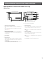
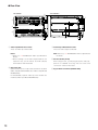

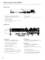
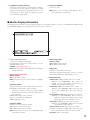


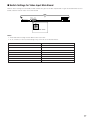

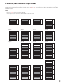
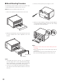
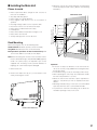

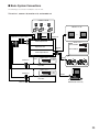
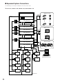
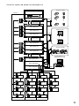


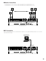
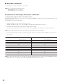
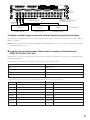
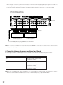
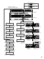
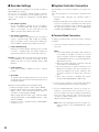
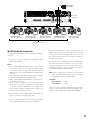

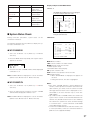

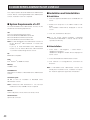


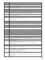

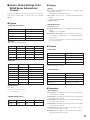
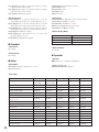
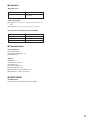


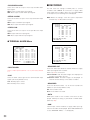
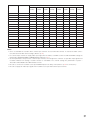
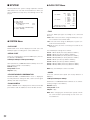

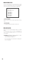

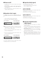

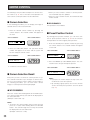
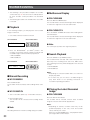

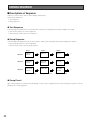

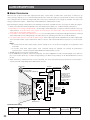


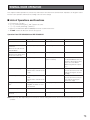

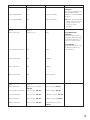
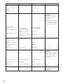
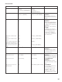
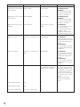


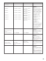
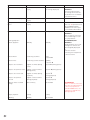
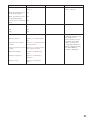
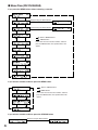


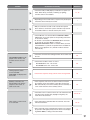

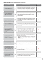
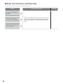
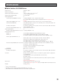


![TSC Series - User Manual [IT]](http://vs1.manualzilla.com/store/data/006117511_1-2773ea5de70324293bc89dec2c59e442-150x150.png)