1
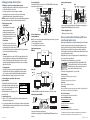
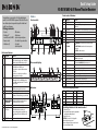
Quick Setup Guide NS-R5101AHD-A AV Home Theater Receiver Congratulations on your purchase of a high-quality Insignia product. Your NS-R5101AHD-A represents the state of the art in home theater system design and is designed for reliable and trouble-free performance. Features Front controls Package contents • Receiver • Rocketboost™ Sender/Receiver (NS-RB1) • Remote control • AA batteries (2) • • • • • • Back view features 9 10 ITEM DESCRIPTION 1 DIGITAL IN jacks 2 3 4 5 6 7 8 9 10 Actual product may vary from image shown. ITEM DESCRIPTION 1 ON/STANDBY button 2 HDMI THRU indicator 3 4 5 6 7 8 FM antenna AM antenna Speaker setup microphone Color labels for speaker cables User Guide Quick Setup Guide FUNCTION Plug the optical digital cable from a game (1) or TV/CD (2) into the upper jacks, or the coaxial digital cable from a Blu-ray disc/DVD into the lower jack. COMPONENT video Plug the cables from a component video source into jacks the #1 (BD/DVD) or #2 (CBL/SAT) jacks. Plug the cables to a component video monitor into the OUT jacks. The jacks are color coded (red, green, and blue) to correspond to the cable connectors. HDMI jacks Plug the HDMI signal input cable from a GAME (IN3), cable/satellite box (IN2), or a BD/DVD player (IN1). Plug the HDMI output signal cable to a TV or monitor into the OUT jack. ANTENNA connectors Connect a 75 ohm FM antenna to the coaxial connector or an AM loop antenna to the wire connectors. MONITOR OUT V (Video) Connect this jack to a TV monitor. Rocketboost™ port Connect the NS-RB1 to this port. For more information on Rocketboost™ Wireless technology, see your User Guide. FRONT SPEAKERS Connect the front speakers to these connectors. SURROUND SPEAKERS Connect the left and right surround speakers and CENTER SPEAKER the center speaker to these connectors. AC power cord Plug this cord into an AC power outlet. Composite Video and Plug the composite video and audio L/R output cables Audio L/R jacks from the indicated devices into these jacks. For video recording, plug the composite video and audio L/R input cables to a VCR or DVR into the OUT jacks. SUBWOOFER Connect the subwoofer to this jack. Front controls features Fluorescent display 11 12 13 14 15 16 17 18 19 Back view FUNCTION Press to turn on your stereo receiver. Lights when the HDMI pass-through function is activated in standby mode. Zone 2 indicator Lights when NS-RB1 is connected to the Rocketboost™ port and turned on. STANDBY indicator Lights red when your stereo receiver is in standby mode. Remote control sensor Receives the signal from the remote control. Display Provides information about receiver functions and settings. SETUP button Press to open the on-screen menus. TUNING / Press TUNING / to tune the radio to the next or previous station. PRESET / Press PRESET / to tune the radio to the next or previous station preset. ENTER Press ENTER to confirm a selection. RETURN button In menu mode, press to return to the main menu. MEMORY button Press to save a radio station preset. Press with the TUNING MODE button to clear presets. TUNING MODE button Press to turn on the receiver tuning mode and listen to the radio. Press with the MEMORY button to clear presets. MASTER VOLUME knob Turn to increase or decrease the volume. Headphone jack Plug your headphones into this jack. Input selector buttons Press to select the input signal source you want. Protective cap Remove when using jack. AUX INPUT VIDEO jack Plug an external video source into this jack. AUX INPUT AUDIO L/R jacks Plug an external sound source into this jack. SETUP MIC jack Plug the Audyssey setup microphone into this jack. AUDIO button Press to access audio settings. Fluorescent display features ITEM 1 2 3 4 DESCRIPTION Audio input indicators Listening mode indicator Audyssey indicators Tuning indicators ITEM 5 6 7 DESCRIPTION SLEEP indicator MUTING indicator DIGITAL display Installing batteries in the remote control 1 Remove the cover. 2 Insert two AA batteries into the compartment matching the polarity indicated. 3 Replace the cover. CAUTION: Do not use Ni-Cd rechargeable batteries in this remote control. Remove the batteries if they are not to be used for an extended period of time. Batteries (AA) Setting up your home theater system 1 Finding a location for your home theater system • Install your home theater system on a stable flat surface. Position your receiver so that it has a direct line of sight to the remote control. • Do not expose your system to extremes of temperature or humidity. • Avoid placing your system on a hot surface such as on top of other hot running equipment. Make sure that there is adequate ventilation to your system. CAUTION: Connect the AC cord only after the speakers, antenna, and all optional equipment have been connected. Never make or change any connections with the power turned on. 2 Placing your speakers 1 Center speaker This speaker enhances the front speakers, making sound movements distinct and providing a full-sound image. In movies it is used mainly for dialog. Position it close to your TV facing forward at about ear level, or at the same height as the front speakers. 2 Front speakers These provide the overall sound. Their role in a home theater system is to provide a solid anchor for the sound image. They should be positioned facing the listener at about ear level, and equidistant from the TV. Angle them inward so as to create a triangle, with the listener at the apex. 3 Subwoofer The subwoofer handles the bass sounds of the LFE (Low-Frequency Effects) channel. The volume and quality of the bass output from your subwoofer will depend on its position, the shape of your listening room, and your listening position. In general, a good bass sound can be obtained by installing the subwoofer in a front corner, or at one-third the width of the wall, as shown. 4 Surround speakers These speakers are used for precise sound positioning and to add realistic ambience. Position them at the sides of the listener, or slightly behind, about two to three feet (60 to 100 cm) above ear level. Ideally they should be equidistant from the listener. For additional information on setting up your speakers, refer to the User Guide. 3 Connecting your speakers to the receiver Speaker configuration The following table indicates the channels you should Number of channels 2 3 4 5 use depending on the number of speakers that you have. Front speakers X X X X For 5.1-channel surround-sound playback, you need five Center speaker X X speakers and a powered subwoofer. Surround speakers X X For additional information on configuring your speakers, refer to the User Guide. To connect the speaker cables: 1 Strip 1/2" to 5/8" (12 to 15 mm) of insulation from the ends of the speaker cables, and twist the bare wires tightly, as shown. 2 Loosen the speaker terminals on the receiver and insert the speaker wires into the terminals. The following illustration shows which speaker should be connected to each pair of terminals. 3 Tighten the terminals to secure the wire. SN 29400381 To connect the subwoofer: Using a subwoofer RCA cable, connect the AV receiver’s SUBWOOFER PRE OUT jack to an input on your powered subwoofer, as shown. Front right speaker Center speaker Powered subwoofer Front left speaker Surround left speaker Surround right speaker 4 Connecting devices Connecting the antenna Note: The receiver won’t pick up any radio signals without any antenna connected, so you must connect the antenna to use the tuner. 1 Connect the FM antenna to your receiver. 2 Connect the AM loop antenna to the receiver. Connecting audio components HDMI cable Receiver Blu-ray disc/DVD player TV or projector Game console Other cables Video Audio Receiver Blu-ray disc/DVD player TV or projector Game console For additional information on deciding which connections to use, refer to the User Guide. Connecting components with HDMI Game console Satellite, cable, or set-top box TV or projector Blu-ray disc/DVD player Connect your components to the appropriate jacks. For information on assigning inputs, see “Setting up HDMI input (HDMI Input menu)” in your User Guide. Connecting external components Front AUX input Back Digital Component Composite video and IN video audio L/R jacks Connect your components to the appropriate jacks. For information on assigning inputs, see “Setting up HDMI input (HDMI Input menu)” in your User Guide. 5 Connecting the power • Plug the power cord into an AC outlet. Your new system features the Audyssey 2EQ® room correction and speaker setup With the supplied calibration microphone, Audyssey 2EQ automatically determines the number of speakers connected, their size (for purposes of bass management), optimum crossover frequencies to the subwoofer (if present), and distances from the primary listening position. Audyssey 2EQ then removes the distortion caused by room acoustics by capturing room acoustical problems over the listening area in both the frequency and time domain. The result is clear, well-balanced sound for everyone. Enabling Audyssey 2EQ lets you also use Audyssey Dynamic EQ®, which maintains the proper octave-to-octave balance at any volume level. For additional information on utilizing Audyssey, see your User Guide. This product includes Rocketboost™ Expandable Wireless Audio Technology. With Rocketboost™ the AV receiver can send wireless audio for surround sound, subwoofer, and 2nd zone and receives wireless audio from other Rocketboost™ devices. For instructions on setting up Rocketboost™, see your User Guide. Troubleshooting For information on troubleshooting, refer to the User Guide. Specifications For information on specifications, refer to the User Guide. FCC Part 15 This device complies with Part 15 of the FCC Rules. FCC warning Changes or modifications not expressly approved by the party responsible for compliance with the FCC Rules could void the user’s authority to operate this equipment. ICES-003 Class B Notice This Class B digital apparatus complies with Canadian ICES-003. One-year limited warranty Visit www.insigniaproducts.com for details. Contact Insignia: For customer service please call 1-877-467-4289 www.insigniaproducts.com Distributed by Best Buy Purchasing, LLC 7601 Penn Avenue South, Richfield, Minnesota, U.S.A. 55423-3645 © 2010 BBY Solutions, Inc. All rights reserved. INSIGNIA is a trademark of BBY Solutions, Inc. Registered in some countries. All other products and brand names are trademarks of their respective owners. ENGLISH 10-0563