1
QVT·102
QVT·102A
Operator Manual
October 1983
2350 Qume Drive-San Jose, California 95131-TWX 910-338-0232-(408) 942-4000
FCC WARNING
This equipment generates, uses, and can radiate radio frequency
energy and if not installed, maintained, and used in accordance
with instructions contained in Qume manuals, may cause interference with radio communications. This equipment has been
tested and found to comply with the limits for a Class A computing
device pursuant to Subpart J of Part 15 of FCC Rules, which are
designed to provide reasonable protection against such interference when operated in a commercial environment. Operation
of this equipment in a residential area is likely to cause interference
in which case the user, at his own expense, will be required to take
whatever measures may be required to correct the interference.
WARNING
Reorder Number 35003A
ADM-3A and ADM-5 are trademarks of Lear Seigler, Inc.-Data Products Division. TeleVideo 910 is a registered trademark of
TeleVideo Systems, Inc. Hazeltine 1500 is a trademark of Hazeltine
Corp. (Esprit Systems, Inc.).
© 1983 Qume Corporation, printed in Taiwan, R.O.C.
Qume, Q, QPW, QumeTrak, Quickload, QVT, Sprint, Sprint Micro,
Speed Feed, Twintellect, TwinTrack, WideTrack, and MicroDrive are
Trademarks of Qume Corporation.
Contents of this publication may be preliminary and/or may be changed at any time
without notice and shall not be regarded as a warranty.
DISPLAY",,MODULE ' "
192·B"()5
The QVT·102lQVT·102A Video Display Terminal
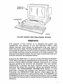
PREFACE
The purpose of this manual is to describe the proper use,
capabilities, and features of the QVT-102TM/QVT-102ATM video
display terminal. Even though its application may vary, users of
either the Qume Videa Terminal, Model 102, or the Model 102A are
encouraged to read this manual to acquire a general understanding,
and thereby facilitate using the terminal to its fullest potential. The
keyboard and display module, the two major components that com·
prise the terminal, are illustrated above.
Following the PREFACE, is a section entitled PRODUCT DESCRIPTION, which outlines the specifications of the terminal. Next, in the
section entitled INSTALLATION, detailed instructions for unpacking and installing the terminal are presented. The next section,
OPERATION, is perhaps the most important section, because it
describes the power On procedure, set-up, and general operator
functions. The PROGRAMMER INFORMATION Section is more
technically oriented and explains the terminal's command set.
Following, the OPERATOR CARE Section offers helpful tips for
maintaining the terminal in good working order. A GLOSSARY and
APPENDIX provide an array of reference information, and an INDEX
concludes the manual with a topical listing of keywords with page
reference.
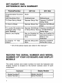
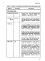
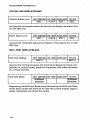
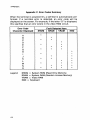
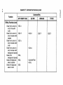
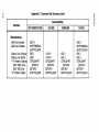
QVT·102/QVT·102A
DIFFERENCE DATA SUMMARY
QVT-102
Feature/Function
QVT-102A
Programmable Function
Keys
None
8
AUX (Auxiliary) Port
Unidirectional
Bidirectional
To Enter Set-up Mode
Depress Setup Key
Depress Ctrl/Shift/
Setup Keys
To Send a Break
Depress Break Key
Depress Shift/Break
Keys
To Locally Re-enable the Depress Shift/Break Depress Shift/Break
Keyboard after it has
or Setup-Setup Keys or Ctrl/Shift/Setupbeen Disabled
Setup Keys
Status Line Display
May be Disabled by May be Disabled by
Command Code or
Command Code
Only
Status Line
Selection
To Display "H" Test
Pattern
Depress Setup-Zero
Keys
Depress Ctrl/Shift/
Setu p-Zero Keys
* * All of the above topics are noted in the manual. * *
RECORD THE SERIAL NUMBER AND MODEL
NUMBER OF YOUR KEYBOARD AND DISPLAY
MODULE
The serial number and model number for both the keyboard and
display module is located on the bottom outside cover of each
component.
Keyboard
Model Number
Serial Number
ii
Display Module
Model Number
Serial Number
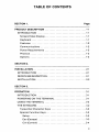
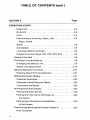
TABLE OF CONTENTS
SECTION 1.
Page
PRODUCT DESCRIPTION ................... " .......... 1·1
INTRODUCTION ......................... " .......... 1·1
Screen/Video Display ............................... 1·1
Keyboard ......................................... 1·1
Features ......................................... 1·2
Communications .................................. 1·2
Power Requirements ............................... 1·3
Physical .......................................... 1·3
Options .......................................... 1·3
SECTION 2.
INSTALLATION ........................................ 2·1
INTRODUCTION ..................................... 2·1
RECEIVINGIINSPECTION ............................. 2·1
INSTALLATION ...................................... 2·2
SECTION 3.
OPERATION .......................................... 3·1
INTRODUCTION ..................................... 3·1
POWERING ON THE TERMINAL ....................... 3·1
USING THE TERMINAL ............................... 3-2
TH E KEYBOARD ..................................... 3-2
Typewriter Character Keys .......................... 3-3
Special Function Keys .............................. 3-3
Setup .......................................... 3-3
Esc (Escape) .................................... 3-3
Ctrl (Control) .................................... 3-4
iii
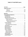
TABLE OF CONTENTS (cont )
SECTION 3.
Page
OPERATION (CONT)
Caps Lock ................................... , .. 3-4
No Scroll ....................................... 3-4
Print ........................................... 3-4
Position Keys: Arrow Up, Down, Left, ................ 3-5
Right, Home
Break .......................................... 3-5
Del (Delete) ..................................... 3-5
Line Feed, Shift/ Line Feed ........................ 3-5
Program Function Keys: PF1, PF2, PF3, PF4 .......... 3-5
Numeric Key Pad .................................. 3-6
The Status Line and Set-up .......................... 3-9
Changing the Status Line ......................... 3-9
Status Line Description .......................... 3-10
General Operator Functions ........................ 3-21
Entering Data From the Keyboard ................. 3-21
Editing the Screen Display .......................... 3-21
Character Overstrike ............................. 3-22
Character Insert/Character Delete .................. 3-22
Line Insert/Line Delete ............................ 3-22
Printing the Screen Display .......................... 3-22
Printing the Entire Screen ......................... 3-22
Printing from the Top of the Screen to ............... 3-23
the Cursor
Printing from the Cursor to the Bottom ............... 3-23
of the Screen
Transmitting (Sending) the Screen Display to ........... 3-23
Host Computer
iv
TABLE OF CONTENTS (cont)
SECTION 3.
Page
OPERATION (CONT)
Send Line ...................................... 3-23
Send Page ..................................... 3-23
Other Function Codes .............................. 3-24
SECTION 4.
PROGRAMMER INFORMATION ........................... 4·1
INTRODUCTION ..................................... 4-1
MONITOR MODE ... , ............... , ................. 4-1
PROGRAM FUNCTION KEYS .............. , .... " ...... 4-4
Program Function Keys: PF1-PF4 ...................... 4-4
(Default Selection)
Program Function Keys: PF1-PF4 .................... 4-4
(Programmable Selection)
CURSOR CONTROL .................................. 4-5
Cursor Movement .............................. : ... 4-5
Cursor Addressing/Cursor Reading .................... 4-7
TAB CONTROL ..................................... 4-12
EDITING FUNCTIONS ................................ 4-13
SEND FUNCTION ................................... 4-16
PRINT FUNCTION ................................... 4-17
VIDEO ATTRIBUTES ................................. 4-19
Screen Attributes ........................' .......... 4-19
Field/Line Attributes ............................... 4-19
Character Attributes ............................... 4-23
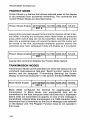
PROTECT MODE .................................... 4-24
TRANSMISSION MODES ............................. 4-24
GRAPHICS MODE ........................ : .......... 4-25
v
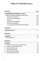
TABLE OF CONTENTS (cont )
SECTION 4.
Page
PROGRAMMER INFORMATION (CONT)
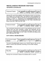
MISCELLANEOUS PROGRAM FUNCTIONS .............. 4-27
Keyboard Lock/Unlock .............................. 4-27
Auto Scroll Enable/Disable .......................... 4-27
Ring Bell ......................................... 4-27
Status Line Display/Blank ........................... 4-28
Self-Test Display/Blank ............................. 4-28
"H" Video Alignment Pattern Display/Blank ............ 4-29
SECTION 5.
OPERATOR CARE ...................................... 5-1
SECTION 6.
GLOSSARY ........................................... 6-1
INTRODUCTION ..................................... 6-1
SECTIONA.
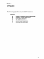
APPEN DIX ............................................ A-1
A
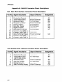
EIAIAUX Connector Pinout Descriptions ................. A-2
B
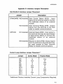
Interface Jumpers Description ........................ A-3
C
Error Codes Summary ............................... A-4
D
US ASCII Code Chart ................................ A-5
E
Control Code Keystrokes ............................. A-6
F
Command Set Summary .............................. A-a
vi
TABLE OF CONTENTS (cont)
SECTION I.
Page
INDEX . ............................................... 1-1
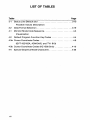
LIST OF ILLUSTRATIONS
Figure
Page
2-1
Unpacking the Terminal ............................. 2-1
2-2
The Rear Panel of the Display Module Pedestal .......... 2-3
2·3
Keyboard Cable Connection ......................... 2-4
to the Display Module
3-1
The Screen Display ................................. 3-2
After Powering On the Terminal
3-2
The Typewriter Character Keys ....................... 3-7
(Foldout 3-1)
3-3
The Special Function Keys ........................... 3-7
(Foldout 3-1)
3-4
The Numeric Key Pad (Foldout 3-1) .................... 3-7
3-5
The Six Status Lines (Foldout 3-2) .................... 3-19
vii
LIST OF TABLES
Table
3-1
Page
Status Line Default and ............................ 3-10
Possible Values Description
3-2
Data Format Selection .............. : .............. 3-19
4-1
Monitor Mode Code Sequence ........................ 4-3
Visualization
4-2
Default Program Function Key Codes .................. 4-4
4-3a Cursor Coordinate Codes ............................ 4-9
(QVT-102/102A, ADM-3A/5, and TVI- 910)
4-3b Cursor Coordinate Codes (HZ-1500 Only) .............. 4-10
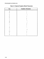
4-4
viii
Special Graphics Mode Characters ................... 4-26
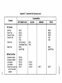
SECTION 1.
PRODUCT DESCRIPTION
INTRODUCTION
This section tabulates the specifications of the QVT-102/QVT-102A
video display terminal. Specifications for both models are the same
except as where noted.
ScreenNideo Display
Screen Module
• 12-inch diagonal screen that features tilt
and swivel for individual operator
comfort.
• Standard non-glare green screen.
Display Format
• 24-lines by 80-character columns.
• 25th Status/Set-up line.
Character Formation
•7
Video Attributes
• Blink, Blank, Underline, Normal/Reverse
Video, and Half Intensity.
Cursor Type
• Blink/Steady, Block/Underline, or
Invisible.
Fields
• Protected and Unprotected Fields.
x
9 matrix in a 9
x
12 cell.
Keyboard
Keyboard
• Detached, low-profile keyboard with
3-position adjustable feet for enhanced
individual operator comfort.
• Alphanumeric typewriter character set.
• Programmable function keys (QVT-102A
only).
• Numeric key pad.
• 5 cursor positioning keys.
• Defeatable audible key click and
character auto repeat.
• 3-key rollover.
• Keyboard lock enable/disable.
Character Set
• 96 ASCII character set.
• 32 control characters.
• 15 graphics (line drawing symbols).
1-1
PRODUCT DESCRIPTION
Features
Emulations
• In addition to its own QVT-102/QVT-102A
command set, three emulations are
available: Hazeltine 1500, Lear Siegler
ADM-3A/5, and Televideo 910.
Editing
• Cursor position/movement keys: Up,
Down, Left, Right, Home.
• Character/Line Insert and Delete.
• Delete to End of Line/Screen.
• Tabbing: Tab, Back Tab, Field Tab.
Rear Panel (Screen
Module Pedestal)
Features
• Power On/Off switch.
• Line fuse: Standard 2 amp-250 Vac.
• AUX-Auxiliary (printer) interface
connector.
• EIA-Host computer (RS-232-C) interface
connector.
Screen Intensity
• Adjustable screen intensity from
potentiometer on right front corner of the
display module pedestal.
Keyboard Connection • Keyboard quick connect/disconnect from
telephone style connector on left-side
corner of display module pedestal.
Screen-Saver
• Automatic video disable after 15 minutes
of inactivity with no loss of data.
Depressing any key will return the video
display. This feature can be disabled.
Set-up Mode
• Menu style (25th status line) set-up
feature with memory storage capability.
Communications
Interface
• Compatible with the EIA RS-232-C
interface standard.
• Bidirectional printer (AUX) port (QVT-102A
only).
Protocol
• X-ON/X-OFF with DTR, X-ON/X-OFF only,
or DTR only.
Modes
• Full or Half Duplex.
• Character/Line/Block data transmission.
1-2
PRODUCT DESCRIPTION
Communications (cont )
Baud Rate
• 50, 75, 110, 134.5, 150, 300, 600, 1200,
1800, 2000, 2400, 3600, 4800, 7200, 9600,
and 19200.
Parity
• Odd, Even, Mark, Space, or No Parity.
Data Word Size
• 7- or 8-data bits.
Power Requirements
Power Requirements
• 95 to 125 Vac, 0.30 A.
• 200 to 264 Vac, 0.15 A.
• 50/60 Hz, 35 W.
Physical
Dimensions
• Screen Module: 14 inches high, 13
inches wide, 12 inches deep.
• Keyboard: 1.5 inches high, 18 inches
wide, 8 inches deep.
Weight
• Screen Module: 19 pounds.
• Keyboard: 3 pounds.
Operating
Temperature
• 0 to 40 degrees Centigrade (32 to 104
degrees Fahrenheit).
Relative Humidity
• 10 to 90%
(non-condensing).
Options
Options
•
•
•
•
Foreign character sets.
Non-glare amber screen.
14-inch diagonal screen (green or amber).
20-mA current loop communications
interface (active or passive).
1-3
SECTION 2.
INSTALLATION
INTRODUCTION
This section describes receivinglinspection and installation of the
QVT-102/QVT-102A video display terminal.
RECEIVING/INSPECTION
Each terminal is packaged in an individual carton for protection during shipment.
Before opening the carton, inspect it for any signs of damage. If
damage is observed, have the delivery agent note the damage on
the shipping document. Note: Some shippers may wish to be present when the carton is opened, if external damage is apparent.
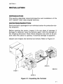
Unpack and inspect the terminal as follows: Refer to Figure 2-1.
STEP 2
Figure 2-1. Unpacking the Terminal
2-1
INSTALLATION
1. Open the carton and place it on its side on a table top or flat
surface.
2. Slide the terminal from the carton.
3. Remove the Styrofoam packing buns, being careful that neither
the keyboard or display module are jostled and fall.
4. Remove the plastic bags that wrap each component. Retain all
packaging materials for possible reshipment.
5. Inspect both the display module and the keyboard for scratches, loose parts, and damage from rough handling. Note any
evidence of such damage on the invoice, and file a claim with the
carrier immediately if the condition of either component so warrants.
6. If damage that might impair the proper operation of the terminal
is detected, contact your service representative for advice and instructions.
7. If the terminal will not be used for some time, it is advisable to
replace the plastic shipping bags for dust protection.
8. When repacking the terminal for shipment or for long storage
periods, use only the original packaging materials.
INSTALLATION
Select a suitable site in which to install your terminal. A good site
offers a clean, well-lighted environment, with a stable platform to
support the terminal at a comfortable height. Install the terminal as
follows:
1. Verify that the power switch on the rear panel of the display
module pedestal is in the OFF position. The rear panel of the
display module pedestal is illustrated in Figure 2-2.
2. Connect the communications cable between the host computer and the connector labeled "EIA" on the rear panel of the
display module pedestal. If necessary, refer to Appendix A for a
pinout description of this connector, and to Appendix B for information concerning optional interface jumper placement.
2·2
INSTALLATION
Figure 2·2. The Rear Panel of the Display Module Pedestal
3. If a printer is to be used, connect the printer to the connector
labeled "AUX" on the rear panel of the display module pedestal. If
necessary, refer to Appendix A for a pinout description of this connector.
4. Connect the power cord from the display module to a grounded
AC outlet.
2·3
INSTALLATION
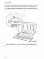
5. Connect the coiled keyboard cable to the connector on the left
front corner of the display module pedestal (refer to figure 2-3).
6. Adjust the height of the keyboard to a comfortable elevation.
1
/
DISPLAY MODULE
PEDESTAL
~~~~~~~~~
632-A-02
Figure 2·3. Keyboard Cable Connection to the Display Module
2-4
SECTION 3.
OPERATION
INTRODUCTION
This section describes how to operate the QVT-102/QVT-102A video
terminal and discusses the following topics: Powering On the terminal; what you should see; adjusting screen intensity; using the
keyboard; and general operator functions, such as editing, printing,
and sending the screen display.
POWERING ON THE TERMINAL
To power On the terminal perform the following steps:
1. Verify that the terminal is properly installed. Check to see that:
• The Power Switch on the rear panel of the display module is in
the OFF position;
• The power cord is plugged into a grounded AC outlet;
• The host computer cable is connected to the EIA Connector;
• If a printer is to be used, it is connected to the AUX Connector,
and that;
• The keyboard cable is connected to its connector on the left
front corner of the display module.
2. Move the Power Switch to the ON position and observe that the
following things occur:
• The margin bell or beeper should sound after about two
seconds;
• In about ten seconds the cursor should appear at its Home
position (the QVT-102 will also display the status line on the
25th line of the screen until it is disabled by command code).
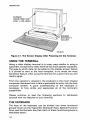
Note: It may be necessary to adjust the screen intensity by
rotating the knob on the right corner of the display module to
make the display visible. Refer to Figure 3-1;
• If an error code is displayed on the screen, refer to Appendix C
for further details and contact your service representative;
• If the terminal appears not to be operating, verify that the
power source is satisfactory, and that the fuse installed on the
rear panel is a good fuse.
3-1
OPERATION
CURSOR
HOME POSITION
LINE 1, COLUMN 1
192·8-05
Figure 3·1. The Screen Display After Powering On the Terminal
USING THE TERMINAL
Using a video display terminal is in many ways similar to using a
typewriter, except that a video terminal has much greater capability.
The ease by which data can be edited on the display screen, before
it is printed or sent to the host computer, is no doubt the most
beneficial feature. After using the terminal for a short time you will
readily agree.
From the operator's viewpoint, the keyboard is the most integral
component because from it data is generated for entry into the host
computer system. A good understanding of the keyboard is
necessary to fully utilize and appreciate all of the terminal's
capabilities.
Please continue to read the following sections to familiarize
yourself with the features of your terminal.
THE KEYBOARD
The keys of the keyboard can be divided into three functional
groups known as the Typewriter Character Keys, Special Function
Keys, and the Numeric Key Pad. Each of these functional groups is
described below.
3·2
OPERATION
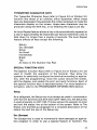
TYPEWRITER CHARACTER KEYS
The Typewriter Character Keys (refer to Figure 3-2 on Foldout 3-1)
function like those of an ordinary office typewriter. When these
keys are depressed, they generate the codes necessary to make the
characters display on the screen. Upper-case characters may be
produced using the Shift key, or by enabling the Caps Lock key.
An Auto Repeat feature allows a key to be automatically repeated at
a rate of approximately 30 characters per second whenever a key is
held down for longer than a couple of seconds. The Auto Repeat
feature affects all keys except the following:
Return
Esc (Escape)
Setup
No Scroll
Home/Clear
Break
Tab
All keys on the Numeric Key Pad.
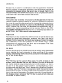
SPECIAL FUNCTION KEYS
The Special Function Keys (refer to Figure 3-3 on Foldout 3-1) are
used to modify the operation of the terminal. They allow the
operator to selectively configure the terminal according to application, alter the programming, move the cursor around the screen,
edit the display, and enable the print and send functions. Each of
the special function keys is described below. For more detailed information, refer to the PROGRAMMER INFORMATION Section.
Setup
As a safeguard, the Setup key must always be used in combination
with the Ctrl (Control) and Shift keys (QVT-102A only; the Setup key
is used singularly on QVT-102). This key allows the operator to enter
and exit the status line at the bottom of the screen. Refer to The
Status Line and Set-up paragraph for a complete description of the
status line and the use of the Setup key.
Esc (Escape)
The Escape key is used to momentarily leave (escape) an application program in order to use a special feature or function. The
3·3
OPERATION
Escape key is used in combination with the typewriter character
keys to specify a command sequence. The Escape key should be
pressed and released before the second key is issued. Refer to the
PROGRAMMER INFORMATION Section for a complete description
of all QVT-102 / QVT-102A escape sequences.
Ctrl (Control)
The Control key is similar in function to the Escape key in that it is
used to enable a special feature or function. However, the Control
key must be used simultaneously with a typewriter character key to
issue a command (similar in action to the Shift key). Commands
which require that the keys be depressed simultaneously are indicated by a hyphen separating the key names. Refer to the PROGRAMMER INFORMATION Section for a complete description of
all QVT-102 / QVT-102A control code sequences.
Caps Lock
The Caps Lock key enables the shift function so that all alpha keys
display as upper-case characters. However, the Caps Lock key is
different from a typewriter shift lock key, because it does not enable
the characters in the shift position on the number keys - these
characters still require that the Shift key be engaged. The Caps
Lock key is an On/Off function key.
No Scroll
The No Scroll key is an On/Off function key which when depressed
once, signals the host computer to stop scrolling of the screen
display. Depressing the No Scroll key a second time enables scrolling of the screen again.
Print
The Print key can be used in three ways. To print all data on the
screen, simply depress the Print key. Secondly, to print all data from
the Home position (top left-hand corner of the screen, i.e., line 1,
column 1) to the present cursor position, use the Print key in conjunction with the Shift key. This is known as a Shift-Print function.
Or thirdly, use the Print key in conjunction with the Control key, a
Control-Print function, to print all data from the present cursor position to the end of the screen. (For data to print as it is positioned on
the display screen, whenever the Print key is used, all null codes are
converted to space codes ).
3·4
OPERATION
Cursor Position Keys: Arrow Up, Down, Left, Right, Home
The cursor position keys are used to move the cursor about the
screen. The arrow keys are repeat keys and move the cursor in the
direction the arrow is pointing on the key cap. The Home key
returns the cursor to the Home position, or location line 1, column 1
on the display screen. Depressing the Home key with the Shift key
(or Clear) clears the screen of data and returns the cursor to the
Home position.
Break
Depressing the Break key transmits a 200- to 250-millisecond space
pulse to the computer. As a safeguard, the Break key must be used
in combination with the Shift key (QVT-102A only; the Break key is
used singularly on QVT-102).
Del (Delete)
Depressing the Delete key issues an ASCII delete (DEL) character to
the host computer.
Line Feed, Shift/Line Feed
Depressing the Line Feed key issues an ASCII line feed (LF) command to the host computer and causes the cursor to be moved
down one line in the same column on the screen. Using the Line
Feed key in combination with the Shift key causes the cursor to be
moved upward in the same column. Visually on the display screen,
the cursor moves as it does when using the Up and Down Cursor
Position keys.
Program Function Keys: PF1, PF2, PF3, PF4
Each of the Program Function keys transmits to the host computer
a special code. A Program Function key may be used by itself, or in
conjunction with either the Shift or Control key to generate a total of
twelve default codes. For user programming instructions (QVT-102A
feature only), refer to the PROGRAMMER INFORMATION Section.
3-5
OPERATION
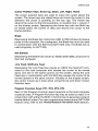
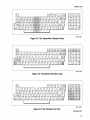
NUMERIC KEY PAD
The Numeric Key Pad (refer to Figure 3-4 on Foldout 3-1) allows
numbers to be entered in calculator fashion. Each number key in
the Numeric Key Pad generates the same characters as the number
keys in the Typewriter Character Set; however, the Numeric Key Pad
keys do not auto repeat. Depressing the Enter key causes a carriage
return and is also used to enable data transmission from the terminal to the host computer (QVT-102/QVT-102A only).
3-6
OPERATION
EJEJEJEJ
DODD
DD[JD
~8Bs
077-C-02
Figure 3·2. The Typewriter Character Keys
~
8D~8a~
EJEJEJEJ
EJDDDDDDDDDDDDD§EJ= DODD
DDDD
CEIJDLJDDDDD DO 0 DOnE]
EJeID D D D 0 r:J DOD 0 0 0 rEJ D
~8Bs
§ [ m D DOD D D [] 0 DO [F1J§]f
I
I
077-C-03
Figure 3·3. The Special Function Keys
~
jE1DD8a~
EJDDDDDDDDDDDDD§El
D LJ DD 0 D D D [] 0 DID n El
EJ ~ DDD Dr:J DODD DO rEJD
r=
[EI]
~[mDDDDDD[]DDDG1J§]r
I
~
077-C-04
Figure 3·4. The Numeric Key Pad
Foldout 3-1
3-7
OPERATION
THE STATUS LINE AND SET·UP
The Status Line is the last line (or 25th line) on the display screen.
The QVT-102 / QVT-102A has six status lines that can be consecutively displayed to view the set-up configuration of the terminal. Each line contains a series of fields, whose contents may be
selectively ordered from the keyboard (some may be selected by
command code). Figure 3-5 on Foldout 3-2 illustrates the status
lines and the selections available between the Default and Possible
values for each field.
Normally, when the Status Line is displayed, it appears in reverse
video. However, the Status Line may be blanked, or suppressed,
from display on the screen.
CHANGING THE STATUS LINE
Changing a status line is accomplished as a 3-key function by
simultaneously depressing the Ctrl/Shift/Setup keys (QVT-102A only; the Setup key is used singularly on QVT-102) to enter the cursor
into the Main Status Line. Once the cursor is in the Main Status
Line, it can be moved into any field, or advanced into any of the remaining five status lines by depressing the Cursor Position keys.
For example, depressing the Down Cursor Arrow key advances the
cursor into the next status line, the Up Cursor Arrow key returns the
cursor to the previous status line, and the Left and Right Cursor Arrow keys move the cursor left or right from field-to-field within a
status line. To change a field from a Default value to a Possible
value, move the cursor into that field; then simply depress the
Space Bar to toggle (or select) the contents of the field.
If a status line is reconfigured and, it is desired that the new selection(s) be "saved," a Shift-S function will write the new values into
memory (all except the PROTECT MODE OFF/ON, KEYBOARD
ON/LOCK, AUXILIARY PORT OFF/ON, MONITOR MODE OFF/ON,
GRAPHICS MODE OFF/ON, and the TRANSPARENT MODE
OFF/ON fields which always assume their default values when the
power is cycled). Performing a Shift-D function will return all the
status lines to their default values; a Shift-R function will recall the
previous "saved" status of the six status lines. Whenever a Shift-S,
Shift-R, or Shift-D function is performed, the cursor will exit the setup sequence and return to its last position on the display; otherwise, depress the Setup key a second time.
3-9
OPERATION
During a set-up sequence, only the following keys and key combinations are functional: Setup, Cursor Position keys, Space Bar,
Shift-S, Shift-R, and Shift-D. The Typewriter Character keys, and the
Esc and Ctrl keys are functional only to enter the H ERE IS message
and to program the Program Function keys (QVT-102A feature only);
the zero key is functional to display an "H" pattern used during
video alignment procedures.
It is recommended that after the terminal is configured for operation with the host system, that the Status Line set-up selections be
recorded as a reference that identifies the terminal's operating
parameters.
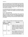
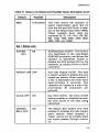
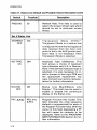
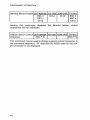
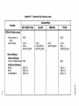
STATUS LINE DESCRIPTION
Table 3-1 describes the default and possible values of each field
within the six status lines. Note: Some status line selections are
available by command code, and in the following table these are
identified by an asterisk (*). Refer to the PROGRAMMER INFORMATION Section for the proper command code to use with the emulation selected.
Table 3-1. Status Line Default and Possible Values Description
Default
Possible
Description
Main Status Line
ON LINE
3-10
CAPS
Capitals. This field is selected by
depressing the Caps Lock key, and
enables all the alpha characters to
display and be transmitted in uppercase. This feature is disabled by
depressing the Caps Lock key a second time.
LOCAL
On Line Mode/Local Mode. On Line
Mode configures the terminal for
communication with the host computer; Local Mode isolates the terminal from the host computer.
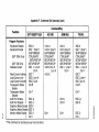
OPERATION
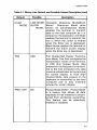
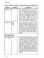
Table 3·1. Status Line Default and Possible Values Description (cont)
Default
Possible
Description
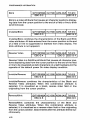
CHAR
MODE
LINE MODE Character Mode/Line Mode/Block
Mode *. Character Mode (also
BLOCK
MODE known as Conversational Mode)
enables the terminal to transmit
data to the host computer as it is
entered on the keyboard. Line Mode
enables the terminal to transmit the
line in which the cursor is located
when the Enter key is depressed.
Block Mode enables the terminal to
transmit the entire screen display
when the Enter key is depressed.
FDX
HDX
Full Duplex/Half Duplex Transmission Mode. This field configures the
transmission mode of the terminal.
In FDX (Full Duplex) Mode, data
entered on the keyboard is transmitted to the host computer only; data
must be echoed back to the terminal
for screen display. In HDX (Half
Duplex) Mode, data entered on the
keyboard is transm itted to the host
computer and is also internally
echoed for screen display.
PROT OFF
ON
Protect Mode Off/On *. Protect Mode
is a feature that allows all data
displayed in half intensity to be protected from accidental overwriting.
This feature can be selectively
enabled or disabled.
3-11
OPERATION
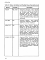
Table 3-1. Status Line Default and Possible Values Description (cont)
Default
Possible
Description
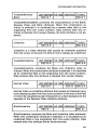
KB ON
KB LOCK
Keyboard On/Lock*. This feature
can be used to disable the keyboard
as a data entry device until a
Keyboard Unlock command is
received from the host computer,
until a set-up sequence is entered,
or until the Shift and Break keys are
depressed.
AUX OFF
ON
Auxiliary Off/On*. This feature
selectively disables or enables the
AUX Port or printer interface.
MON OFF
ON
Monitor Mode Off/On*. Monitor
Mode is a feature that enables the
display of all control codes and
escape sequences in addition to the
alphanumeric character set. Commands are not executed when
Monitor Mode is selected. For proper operation, the Line Wrap feature
should also be enabled.
GRAPH OFF ON
Graphics Off/On*. Graphics Mode is
a special appl ications feature that
reconfigures the terminal for 15 line
drawing symbols. For a complete
tabulation, refer to the PROGRAMMER INFORMATION Section. With
the Graphics Mode disabled, the
complete alphanumeric character
set is available.
3·12
OPERATION
Table 3·1. Status Line Default and Possible Values Description (cont)
Default
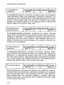
9600
Possible
15·Possible
Description
This field allows the operator to
select transmission baud rate for
both the EIA and AUX Ports. In addition to the default baud rate of 9600,
fifteen possible baud rates are
available: 50, 75,110,134.5,150,300,
600, 1200, 1800, 2000, 2400, 3600,
4800, 7200, and 19200.
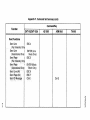
Set 1 Status Line
AUXlKB:
AUX
KB
AUXlKeyboard On/Off"'. This field is
only applicable to· the Lear·Sieger
ADM·3A/5 emulation, and allows the
operator to selectively enable or
disable the AUX (printer) Port or the
keyboard, by using a Ctrl-N or Ctrl-O
command.
REPEAT ON OFF
Auto Key Repeat On/Off. This field
is used to enable or disable the auto
repeat key feature. When enabled, if
a key is depressed and held down
approximately 2 seconds, that
character will repeat at a rate of approximately 30 characters per
seconds.
CLICK OFF
ON
Key Click Off/On. The Click On/Off
feature enables or disables the audible click sound of the keys being
depressed.
MARGIN
BELL OFF
ON
The Margin BellOn/Off. This field
enables or disables the right margin
alarm feature. When enabled, a
"beep" sound will be emitted when
the cursor passes through column
73.
3·13
OPERATION
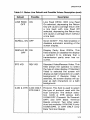
Table 3·1. Status Line Default and Possible Values Description (cont)
Default
Possible
Description
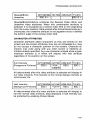
EIA/CL: EIA
CL
EIA RS-232-C/Current Loop Interface. This field is used to select the
type of communications interface
used on the EIA or host computer
port. EIA is the default selection and
identifies an RS-232-C interface. If
the terminal is equipped with the
current loop option, CL may be
selected to enable the 20-ma current
loop interface (Oefault Passive).
E.O.M. NUL
ETX
EOT
CR
End of Message Terminator*. This
field allows the operator to select
the type of ASCII code identifier that
signifies to the host computer the
conclusion of a transmission. Four
E.O.M. terminators are available:
NUL (Null, Ctrl-@); EOT (End of
Transmission, Ctrl-O); ETX (End of
Text, Ctrl-C); or CR (Carriage Return,
Ctrl-M).
Set 2 Status Line
LINE WRAP
ON
3-14
OFF
Line Wrap On/Off. This field is used
to select the line wrap feature which
moves the cursor from the 80th column of a given line to the first unprotected position of the next line
when the active position is shifted
one column to. the right. If ON is
selected, this feature is enabled; if
OFF is selected, this feature is
disabled. When disabled, the cursor
wi II not move beyond the 80th column position and all data at this
position will be subsequently overwritten.
OPERATION
Table 3·1. Status Line Default and Possible Values Description (cont)
Default
LINE FEED
OFF
Possible
ON
Description
Line Feed Off/On. With Line Feed
On selected, depressing the Return
key will cause a carriage return with
a line feed; with Line Feed Off
selected, depressing the Return key
will cause a carriage return without
a line feed.
SCRbLL ON OFF
Scroll On/Off*. This field enables or
disables automatic scrolling of the
screen display.
DISPLAY PE ON
OFF
Display Parity Error Off/On. This
field enables or disables the display
a symbol ( {) to indicate that a
transm iss ion parity error has occurred.
STD VID
Standard Video/Reverse Video. This
field allows the operator to select
the type of video display. If Standard
Video is selected the screen will
display as light characters on a dark
background; if Reverse Video is
selected, the screen display will appear as dark characters on a light
background.
REV VID
X-ON & OTR X-ON ON LY
OTR ONLY
Protocol. This field is used to select
the type of protocol used with the
host computer. The default selection X-ON & DTR allows both
X-ON/X-OFF (Transmit On/Transmit
OFF) and DTR (Data Terminal
Ready) protocol. Two other selections are available: X-ON ONLY (only
X-ON/X-OFF), or DTR ONLY (only
Data Terminal Ready).
3-15
OPERATION
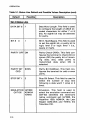
Table 3·1. Status Line Default and Possible Values Description (cont)
Default
Possible
Description
Set 3 Status Line
DATA BIT 8
7
Data Word Length. This field is used
to configure the length of ASCII encoded characters for either 7 or 8
bits. An eighth bit may be selected
for parity.
BIT8
1
Bit 8 - Mark/Space. This field is used
to set the eighth bit, or parity bit to
logic level 0 or logic level 1 (Le.,
space or mark).
0
PARITY OFF ON
Parity Check Off/On. This field configures the terminal to check (On) or
ignore (Off) the parity bit of incoming data; also, adds parity to
transmitted data when ON is
selected.
PARITY BIT
ODD
EVEN
Parity Bit Odd/Even. This field configures the terminal for odd or even
parity.
STOP BIT 1
2
Stop Bit Select. This field is used to
select the number of stop bits
following a data word: 1 (one) or 2
(two).
EMULATION HZ1500
QVT102
ADM-5A
TVI910
3-16
Emulation. This field is used to
select the emulation command set:
QVT102 identifies the terminal's
native command set; HZ1500, the
Hazeltine 1500; ADM-5A, the Lear
Siegler ADM-3A/5; and TV1910, the
Televideo 910.
OPERATION
Table 3·1. Status Line Default and Possible Values Description (cont)
Default
Possible
Description
Set 4 Status Line
CURSOR UL BLOCK
Cursor Type. This field allows the
operator to select either an
Underline or Block type cursor.
CURSOR
BLINK
Cursor Attribute. This field allows
the operator to select the cursor at·
tribute: Blinking or Steady (always
On).
STEADY
HERE IS:
TIME OFF
Here Is Message. The Here Is field is
a special purpose field that allows
an operator or programmer to enter
a message that specifically identifies a terminal to the host computer when an ASCII enquiry code
(ENQ, Ctrl-E) is received. In the Here
Is field, the first and last characters
used must be the same, since these
characters act as message
delimiters (delimiters are not
transmitted or displayed). Use a cur·
sor key to exit this field before performing a Save function (Shift-S).
ON
Screen-Saver Feature. This field is
used to enable or disable the
automatic screen-saver feature.
After approximately 15 minutes of
inactivity (no host or operator input)
the display is automatically dis·
abled to preserve the screen
phosphor, although the screen RAM
contents are held intact. When data
from the host is received or any key
depressed, all screen contents are
again displayed without loss of
data.
OPERATION
Table 3·1. Status Line Default and Possible Values Description (cont)
Default
FREQ 60
Possible
50
Description
Refresh Rate. This field is used to
select the screen refresh rate which
should be set to eliminate screen
flicker.
Set 5 Status Line
XPARENT
OFF
ON
Transparent Mode Off/On*.
Transparent Mode is a feature that
configures the terminal to bypass all
data received from the host computer to the to the AUX (printer) port.
Such data is not displayed, when
Transparent Mode is selected.
KB TYPE:
US
GM
Keyboard Type: US/German. This
field allows a choice of keyboard
type (character set): U.S. or German.
Note: If the German keyboard type is
selected, it is also necessary to install a jumper on the Logic PCB and
the appropriate replacement key
caps. Consult your service representative for further information.
STATUS
OFF
ON
Status Line Blank/Status Line
Display*. This field may be used to
enable or disable the continuous
display of the Status Line.
PF1: A@ M
PF2: thru
S-PF4:
Program Function Key Codes. This
field indicates the code sequence
(default or programmed) for each of
the Program Function keys. With the
cursor in this field, depressing a PF
key will cause its contents to be
displayed. Refer to the PROGRAMMER INFORMATION Section for further information.
3·18
OPERATION
Default
Possible
(Main)
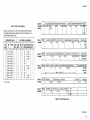
Table 3·2. Data Format Selection
CAPS
ON LINE CHAR MODE FOX PROT OFF KBON
HDX
LOCAL LINE
ON KB LOCK
BLCK
AUXOFF (MON) OFF GRAPH OFF
ON
ON
ON
50
t
Data can be encoded in anyone of the following format combinations. Make the appropriate selection from the Set 3 Status Line to
yield the Desired Data Format.
Desired Data Format
7 Bit
ASCII
Bit
8
Parity
7
7
7
7
7
7
7
7
7
7
7
7
None
None
None
None
Mark
Mark
Mark
Mark
Space
Space
Space
Space
Odd
Odd
Even
Even
None
None
Odd
Even
None
None
Odd
Even
* = Don't
Care.
7200
Set 3 Status Line Selection
Stop
Bits
Data
Bit 8/7
Bit 8
1
2
1
2
1
2
1
1
1
2
1
1
7
7
7
7
7
7
8
8
8
8
8
8
*
*
*
*
0/1
1
1
1
1
0
0
0
0
Default
Possible
SET 1
AUXlKB: AUX
KB
Default
Possible
SET 2
LINE WRAP ON
OFF
Default
Possible
SET 3
REPEAT ON
OFF
CLICK OFF
ON
MARGIN BELL OFF
ON
EIAlCL: EIA
CL
Parity Parity Bit Stop
Off/On OddlEven Bit 1/2
On
On
On
On
Off
Off
On
On
Off
Off
On
On
*
*
1
2
1
2
1
2
Odd
Even
*
*
*
*
1
2
Odd
Even
*
*
Odd
Odd
Even
Even
9600
19200
DATA BIT 8
7
LINE FEED OFF SCROLL ON
ON
OFF
BIT80
1
PARITY OFF
ON
DISPLAY PE OFF
ON
PARITY BIT ODD STOP BIT 1
EVEN
2
....-------------------- Refer to Table 3-2 --------------------~
I
Default
Possible
SET 4 CURSOR UL
CURSOR BLINK
HERE IS:
BLOCK
STEADY I
Default
Possible
SET 5
XPARENT OFF
ON
KB TYPE: US
GM
STATUS LINE OFF
ON
•
STD VID
REV VID
E.O.M.: NUL
ETX
EOT
CR
X-ON & DTR
X-ON ONLY
DTR ONLY
EMULATION QVT102
HZ1500
ADM-5A
TVI910
TIME OFF
ON
FREQ 60
50
,
PF1:
S-PF4:
Figure 3·5. The Six Status Lines
Foldout 3-2
3-19
OPERATION
GENERAL OPERATOR FUNCTIONS
ENTERING DATA FROM THE KEYBOARD
After the terminal is configured for use with the host computer
system, operator activity begins by "keyboarding" data. As an exercise, first place the terminal in Local Mode, and then proceed
through the following steps:
• Type several lines of data while observing how the characters are
displayed on the screen. Note how the cursor "wraps around" to
the left margin of the next line after each preceding line is completed; it is not necessary to use the Return key as with many
typewriters. Line Wrap is a selectable feature available from the
Set 2 Status Line.
• Depress and hold down a character key and observe that the
character automatically repeats on the screen. Key Repeat is a
selectable feature available from the Set 1 Status Line.
• Next, move the cursor about the screen with the cursor arrow
keys and see that the cursor always moves in the direction that
the arrow on the key is pointing.
• Depress the Home key and observe that the cursor immediately
returns to its Home position on the display screen, i.e., Line 1,
Column 1.
• To erase the screen or clear it of all data, simultaneously depress
the Shift and Home Clear keys. After the screen is cleared, the
cursor is returned to the Home position.
EDITING THE SCREEN DISPLAY
Many times it is necessary to edit data on the display screen for the
purpose of correcting mistakes, entering a revision, etc. Perhaps
the most used editing features are Character Overstrike, Character
Insert/Character Delete, and Line Insert/Line Delete. These features
are described below and require the use of an Escape sequence (except Character Overstrike). Refer to the PROGRAMMER INFORMATION Section, or to the Command Set Summary in Appendix F for
specific applications information about the various editing commands.
OPERATION
Character Overstrike
Character overstrike is a feature that allows the operator to position
the cursor under a character, key a new character, and have the new
character display in place of the original character.
Character Insert/Character Delete
To insert a character, move the cursor to the position where the new
character is desired and enter an ESC Q command. A blank space
will appear above the cursor in which the character to be inserted
can be entered. When a character is inserted, all data from the cursor to the end of the line is moved one character position to the
right (any data in column 80 will be lost). To delete a character,
move the cursor under the character to be deleted and enter an ESC
W command. The character will be blanked from the display screen
and all data that was formerly to its right will move one space to the
left to fill the vacated space. A blank space will be inserted at column 80.
Line Insert/Line Delete
To insert a line, move the cursor to the position where the new line
is desired. Enter an ESC E command and observe that all data from
the present cursor line and below is scrolled downward one line. A
blank line will appear above the former cursor line with the cursor
located in column one. Within the blank line, new data can now be
entered. To delete a line, move the cursor to the line to be deleted
and enter an ESC R command. That line will be blanked from the
display screen, and the data below will scroll upward to fill the line
that was deleted.
PRINTING THE SCREEN DISPLAY
Three print options are available to print the data displayed on the
screen. The operator can elect to print the entire screen, to print
from the top of the screen to the cursor, or to print from the cursor
to the bottom of the screen. These print options are described
below. Note: Print command sequences are valid for the QVT102/QVT-102A command set only.
Printing the Entire Screen
To print the entire screen, simply depress the Print key or issue an
ESC P command. For data to print as it is displayed on the screen,
whenever the Print key is used all null codes are automatically converted to space codes.
~.??
OPERATION
Printing from the Top of the Screen to the Cursor
To print from the top of the screen to the cursor position,
simultaneously depress the Shift and Print keys or issue an ESC N
command.
Printing from the Cursor to the Bottom of the Screen
To print from the cursor position to the bottom of the screen,
simultaneously depress the Control and Print keys or issue an ESC
o command.
TRANSMITTING (SENDING) THE SCREEN DISPLAY TO THE HOST
COMPUTER
When the terminal is configured to use the QVT-102/QVT-102A command set, data may be transmitted to the host computer by
depressing the Enter key or by issuing a specific send command to
transmit a select line or page of data (Line or Block Mode). All other
emulations transmit data to the host in Character Mode only. Refer
to the PROGRAMMER INFORMATION Section for further information.
Send Line
Sending a given line of data to the host system may be accomplished in two ways. First, by using the Enter key, if the terminal is
configured to use the QVT-102/QVT-102A command set and is in
Line Mode, depressing the Enter key will cause the terminal to send
only the unprotected data on a given cursor line. Secondly, by issuing an ESC 4 command, only full intensity data on a given cursor
line will be transmitted; issuing an ESC 6 command will cause all
data (protected and unprotected) on the a given cursor line to be
transmitted to the host.
Send Page
Sending a given page or screen of data to the host system may be
accomplished in two ways. First, by using the Enter key, if the terminal is configured to use the QVT-102/QVT-102A command set and
is in Block Mode, depressing the Enter Key will cause the terminal
to send only unprotected screen data. Secondly, by issuing an ESC
5 command, only full intensity data on a given display page will be
transmitted; issuing an ESC 7 command will cause all data (protected and unprotected) on a given display page to be transmitted
to the host.
OPERATION
OTHER FUNCTION CODES
Refer to the PROGRAMMER INFORMATION Section for a functional tabulation and description of all commands according to
emulation. This information is also presented in abbreviated format
in the Command Set Summary, Appendix F.
~-?4
SECTION 4.
PROGRAMMER INFORMATION
INTRODUCTION
This section describes the command set of the QVT-102/QVT-102A
video terminal and explains in more detail those topics introduced
in the preceding section. This section assumes that the reader is
already familiar with the proper operation of the terminal.
Refer to the Appendix for the following information as necessary:
• US ASCII Code Set (Appendix D),
• Control Codes (Appendix E),
• Command Set Summary (Appendix F).
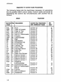
MONITOR MODE
Monitor Mode provides the programmer with a means of verifying
the use of command codes, by enabling the terminal to display all
code sequences (refer to Table 4-1) as they are entered along with
alphanumeric characters. It should be noted that command codes
are not executed when Monitor Mode is active. Also, for proper
operation, enable the line wrap feature.
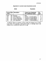
Monitor Mode is controlled by the following code sequences:
Monitor Mode Enable QVT-1021102A HZ-1500 ADM-3A15 TVI-910
Ctrl-1
ESC U
Ctrl-1
ESC U
Ctrl-1
Ctrl-1
Issuing this command configures the terminal to display all host
computer and keyboard entries (alphanumeric and control
characters). Keyboard entries are sent to the host computer only if
the the terminal is On Line.
PROGRAMMER INFORMATION
Monitor Mode Disable QVT-1 0211 D2A HZ-1500 ADM-3A/5 TVI-910
Ctrl-2
ESC X
Ctrl-2
ESC X
ESC u
ESC u
Ctrl-2
Ctrl-2
Issuing this command disables the Monitor Mode; control
characters are not displayed.
Display Select Control QVT-1 0211 02A HZ-1500 ADM-3A/5 TVI-910
Character
ESC F N
ESC F N
This command may be used to display a select control character. In
the command sequence, "N" specifies the ASCII code for the control character to be displ,ayed.
4-2
PROGRAMMER INFORMATION
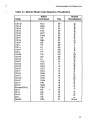
Table 4·1. Monitor Mode Code Sequence Visualization
Code
Ctrl·@
Ctrl·A
Ctrl-B
Ctrl-C
Ctrl-D
Ctrl-E
Ctrl-F
Ctrl-G
Ctrl-H
Ctrl-I
Ctrl-J
Ctrl-K
Ctrl-L
Ctrl-M
Ctrl-N
Ctrl-O
Ctrl-P
Ctrl-Q
Ctrl-R
Ctrl-S
Ctrl-T
Ctrl-U
Ctrl-V
Ctrl-W
Ctrl-X
Ctrl-Y
Ctrl-Z
Escape/Ctrl-[
Ctrl-\
Ctrl-]
Ctrl-A
Ctrl-_
Delete
ASCII
Command
Null
SOH
STX
ETX
EOT
ENQ
AK
BEL
BS
HT
LF
VT
FF
CR
SO
SI
DLE
DC1
DC2
DC3
DC4
NAK
SYN
ETB
CAN
EM
SUB
ESC
FS
GS
RS
US
DEL
Hex
•
00
01
02
03
04
05
06
07
08
09
OA
OB
OC
OD
OE
OF
10
11
12
13
14
15
16
17
19
19
1A
1B
1C
1D
1E
1F
7F
Screen
Visual ization
@
A
B
C
D
E
F
G
H
1.
1.
K
.b
M
N
Q
E.
Q
R
~
~
U
V
W
X
Y
Z
[
\"
T
7\
-
None
4-3
PROGRAMMER INFORMATION
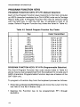
PROGRAM FUNCTION KEYS
PROGRAM FUNCTION KEYS: PF1·PF4 (Default Selection)
Each of the Program Function keys transmits to the host computer
an ASCII character bracketed by a Ctrl-A (SOH) code and a Carriage
Return (CR) code. A Program Function key may be used by itself,
with the Shift key, or with the Ctrl key, to generate a total of 12
codes. Default Program Function key codes are listed in Table 4-2.
Table 4·2. Default Program Function Key Codes
1
2
3
4
5
6
7
8
9
10
11
12
Key
Code Transmitted
PF1
PF2
PF3
PF4
Shift-PF1
Shift-PF2
Shift-PF3
Shift-PF4
Control-PF1
Control-PF2
Control-PF3
Control-PF4
Ctrl-A @ CR
Ctrl-A A CR
Ctrl-A B CR
Ctrl-A C CR
Ctrl-A D CR
Ctrl-A E CR
Ctrl-A F CR
Ctrl-A G CR
Ctrl-A H CR
Ctrl-A I CR
Ctrl-A J CR
Ctrl-A K CR
PROGRAM FUNCTION KEYS: PF1·PF4 (Programmable Selection)
The first 8 Program Function Key code values listed in Table 4-2
above may be user programmed from the keyboard to include any 8
ASCII characters. Programmable Function keys are a feature of the
QVT-102A only.
'
To program a Function Key from the keyboard proceed as follows:
• Enter Set-up Mode (CtrI/ShiftiSetup) and move the cursor into the
last field of the Set 5 Status Line.
• Depress the Function key to be programmed; PF1 through
Shift/PF4.
4-4
PROGRAMMER INFORMATION
• Enter a start delimiter (any character that is not used in the data
string that is to be the contents of that Function key). Note that
delimiters do not display.
• Enter the desired data string. A maximum of 8 ASCII characters
may be selected.
• Enter the trailing delimiter (the trailing delimiter must be the
same character as that used for the start delimiter).
• Repeat the above steps to program the contents of any of the remaining Programmable Function keys.
• To "save" the programmed contents of the Program Function
key(s), first exit the cursor from the field, then issue a Shift-So
CURSOR CONTROL
Cursor control may be simply moving the cursor about the screen
(Home, Right, Left, Up, Down, etc.), assigning the cursor to a
discrete location (cursor addressing), or enquiring of the terminal
the active position of the cursor (read cursor). Each of these cursor
control functions is discribed as follows:
CURSOR MOVEMENT
Cursor Home
I
I
QVT-1 0211 02A HZ-1500 ADM-3A/5 TVI-91 0
f\JCtrl-R
Ctrl-A
Ctrl-A
Ctrl-A
Depressing the Home key or issuing a Cursor Home command
causes the cursor to exit its current position and be relocated at the
Home position on the display screen.
Cursor Right
I
QVT-102l102A HZ-1500 ADM-3A/5 TVI-910
Ctrl-L
Ctrl-L
Ctrl-L
Ctrl-P
I
Depressing the Cursor Right Arrow key, the Shift and Backspace
keys, or issuing a Cursor Right command relocates the cursor one
character position to the right. If the Key Repeat feature is enabled,
the cursor will advance until the key is released or transmission of
the command stopped. The cursor will line wrap regardless of the
Line Wrap selection on the Status Line, and advance through any
protected fields encountered.
4-5
PROGRAMMER INFORMATION
Cursor Left
QVT-102l102A HZ-1500 ADM-3A/5 TVI-910
Ctrl-H
Ctrl-H
Ctrl-H
Ctrl-H
Depressing the Cursor Left Arrow Key, the Backspace key, or issuing a Cursor Left command relocates the cursor one character position to the left. If the Key Repeat feature is enabled, the cursor will
advance unti I the key is released or transmission of the command
stopped. The cursor will line wrap regardless of the Line Wrap
selection on the Status Line, and advance through any protected
fields encountered.
Cursor Up
QVT-1 0211 02A HZ-1500 ADM-3A/5 TVI-910
f\JCtrl-L
Ctrl-K
Ctrl-K
Ctrl-K
Depressing the Cursor Up Arrow Key, the Shift and Linefeed keys,
or issuing a Cursor Up command relocates the cursor upward in the
same column. If the Key Repeat feature is enabled, the cursor will
advance upward and scroll within a given column, until the key is
released or transmission of the command stopped. The cursor will
advance through any protected fields encountered.
Cursor Down
QVT-102l102A HZ-1500 ADM-3A/5 TVI-910
Ctrl-J
f\JCtrl-K
Ctrl-J
Ctrl-J
Ctrl-J
Depressing the Cursor Down Arrow Key, the Linefeed key, or issuing a Cursor Down command relocates the cursor one line
downward in the same column. If the Key Repeat feature is enabled,
the cursor will advance downward and scroll within a given column,
until the key is released or the transmission of the command·
stopped. The cursor will advance through any protected fields encountered.
4-6
PROGRAMMER INFORMATION
Carriage Return
QVT-102J102A HZ-1500 ADM-3A/5 TVI-910
Ctrl-M
Ctrl-M
Ctrl-M
Ctrl-M
Depressing the Carriage Return key, the Enter key, or issuing a Carriage Return command causes the cursor to be relocated to column
1 of the current cursor line. If Line Feed is enabled, the cursor will
advance to column 1 of the next line. With Auto Scroll enabled
when line 24 is completed, the display will scroll up one line and the
cursor will wrap to column 1 of line 24. If Auto Scroll is disabled,
when line 24 is completed the cursor will return to Home and the
display will be overwritten.
New Line
QVT-102J102A HZ-1500 ADM-3A/5 TVI-910
Ctrl-_
Ctrl-_
Issuing a New Line command advances the cursor to column 1 of
the following line. With the Auto Scroll feature enabled, if the cursor
is on the 24th line when a New Line command is issued, the screen
will scroll upward one line and the cursor will advance to column 1
of the new 24th line. If the Auto Scroll feature is disabled, the cursor
will move to the Home position and the display will be overwritten.
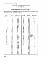
CURSOR ADDRESSING/CURSOR READING
Cursor addressing/reading offers the capability of assigning the
cursor to specific line and column coordinates on the display
screen, or enquiring of the terminal the coordinates of the cursor's
location. Refer to the appropriate Cursor Coordinate Codes table.
Address Cursor
QVT-102J102A HZ-1500 ADM-3A/5
TVI-91 0
ESC= Line# "-JCtrl-Q ESC = Line# ESC = Line#
Col#
Col#
Col#Line#
Col#
Issuing this command assigns the cursor to specific line and column coordinates on the current display page. In the escape sequences, "#" equals the ASCII line and column equivalent values.
Refer to the appropriate Cursor Coordinate Codes table for the
emulation in use.
4-7
PROGRAMMER INFORMATION
Read Cursor Address QVT-1 0211 02A HZ-1500 ADM-3A/5 TVI-910
rvCtrl-E
ESC?
ESC?
Issuing this command causes the terminal to output the cursor address coordinates to the host computer in the format: Line, Column,
Carriage Return (Column, Line, Carriage Return for HZ-1500 only).
Refer to the appropriate Cursor Coordinate Codes table for the
emulation in use.
Load Cursor Line
QVT-1 0211 02A HZ-1500 ADM-3A/51 TVI-910
ESC [ Line #
rSC [Line#
Issuing this command assigns the cursor to a specific line within
the current cursor column.
Load Cursor Column
QVT-1021102A HZ-1500 ADM-3AI5I TVI-91 0
ESC]CoI#
ESC]CoI#
I
Issuing this command assigns the cursor to a specific column
within the current cursor line.
4-8
PROGRAMMER INFORMATION
Table 4·3a. Cursor Coordinate Codes
(QVT·102l102A, ADM·3A/5, and TVI·910)
Code Sequence: ESC
Line
= Line # Col #
Column
Line # Character Col # Character Col # Character Col # Character
1
2
3
4
5
6
7
8
9
10
11
12
13
14
15
16
17
18
19
20
21
22
23
24
Space
!
"
#
$
0/0
&
,
(
)
*
+
,
I
0
1
2
3
4
5
6
7
1
2
3
4
5
6
7
8
9
10
11
12
13
14
15
16
17
18
19
20
21
22
23
24
25
26
27
Space
!
"
#
$
0/0
&
,
(
)
*
+
,
I
0
1
2
3
4
5
6
7
8
9
28
29
30
31
32
33
34
35
36
37
38
39
40
41
42
43
44
45
46
47
48
49
50
51
52
53
54
,
<
=
>
?
@
A
B
C
D
E
F
G
H
I
J
K
L
M
N
0
P
Q
R
S
T
55
56
57
58
59
60
61
62
63
64
65
66
67
68
69
70
71
72
73
74
75
76
77
78
79
80
V
W
X
y
Z
[
\
]
A
-
,
a
b
c
d
e
f
9
h
i
j
k
I
m
n
0
U
4-9
PROGRAMMER INFORMATION
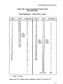
Table 4·3b. Cursor Coordinate Codes
(HZ·1500 Only)
Code Sequence: ""Ctrl·Q Col # Line #
Note: It is recommended to avoid the use of codes in column 0 and
column 1 of the ASCII Code Chart.
Line #
Col #
Character
Line #
Col #
Character
0
1
2
3
4
5
6
7
8
9
10
11
12
13
14
15
16
17
18
19
20
21
22
23
0
1
2
3
4
5
6
7
8
9
10
11
12
13
14
15
16
17
18
19
20
21
22
23
24
25
26
27
28
29
30
31
NUL
SOH
STX
ETX
EOT
ENQ
ACK
BEL
BS
HT
LF
VT
FF
CR
SO
SI
DLE
DC1
DC2
DC3
DC4
NAK
SYN
ETB
CAN
EM
SUB
ESC
FS
GS
RS
US
0
1
2
3
4
5
6
7
8
9
10
11
12
13
14
15
16
17
18
19
20
21
22
23
32"'"
33
34
35
36
37
38
39
40
41
42
43
44
45
36
47
48
49
50
51
52
53
54
55
56
57
58
59
60
61
62
63
SP
4-10
!
"
#
$
0/0
I
&
,
(
)
*
+
,
Read
Cursor
Address
Output
I
0
1
2
3
4
5
6
7
8
9
,
<
=
>
?
PROGRAMMER INFORMATION
Table 4·3b. Cursor Coordinate Codes (cont)
(HZ·1500 Only)
Code Sequence:
Line #
0
1
2
3
4
5
6
7
8
9
10
11
12
13
14
15
16
17
18
19
20
21
22
23
Col #
64
65
66
67
68
69
70
71
72
73
74
75
76
77
78
79
~Ctrl·Q
Character
@
A
B
C
D
E
F
Read
Cursor
Address
Output
G
H
I
J
K
L
M
N
0
P
Q
R
S.
T
U
V
W
X
Y
Z
[
\
]
A
-
Col # Line #
Line #
0"
1
2
3
4
5
6
7
8
9
10
11
12
13
14
15
16
17
18
19
20
21
22
23
Col #
Character
0"
1
2
3
4
5
6
7
8
9
10
11 Read
Read
Cursor
Cursor 12
Address
Address
Output
Output 13
14
15
16
17
18
19
20
21
22
23
24
25
26
27
28
29
30
See Note
,
a
b
c
d
e
f
9
h
i
j
k
I
m
n
0
P
q
r
s
t
u
V
w
X
y
z
{
I
}
~*
DEL
= Lead-In Code.
Note: Hex 7F =Read cursor address output for column 31.
*
A.11
PROGRAMMER INFORMATION
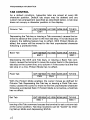
TAB CONTROL
As a default condition, typewriter tabs are preset at every 8th
character position. Defau It tab stops may be deleted and any
custom tab arrangement specified as described below. A tab stop
does not occupy a character position in the display.
Column Tab
QVT-102/102A HZ-1500 ADM-3A/5 TVI-910
Ctrl-I
Ctrl-I
Depressing the Tab key or issuing a Tab command, causes the terminal to advance the cursor to the next tab stop. If no tab stops are
present, the tabbing feature has no effect. With Protect Mode enabled, the cursor will be moved to the first unprotected character
following a protected field.
Back Tab
QVT-102/1 02A HZ-1500 ADM-3A/5 TVI-910
ESC I
ESC I
Depressing the Shift and Tab keys, or issuing a Back Tab command, causes the terminal to move the cursor back to the previous
tab stop on the current line, or to column 1 if the cursor is at the first
tab stop on a line. Protect Mode has no affect.
Field Tab
QVT-102/102A HZ-1500 ADM-3A15 TVI-910
Ctrl-I
Ctrl-I
With the Protect Mode enabled, the cursor moves as defined for
Column Tab. Depressing the Tab key or issuing a Field Tab command, causes the cursor to move to the first unprotected character
following a protected field. If Protect Mode is not active, a field tab
has no affect.
Set Tab
QVT-102/102A HZ-1500 ADM-3A15 TVI-910
ESC 1
ESC 1
Issuing a Set Tab command causes the terminal to set a column tab
at the cursor position. Tab stop locations can be "saved" byentering Set-up Mode and depressing Shift-So .
4-12
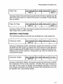
PROGRAMMER INFORMATION
Clear Tab
QVT-1 0211 02A HZ-1500 ADM-3A/5 TVI-910
ESC 2
ESC 2
Issuing a Clear Tab command causes the terminal to delete any tab
stop from the column in which the cursor is located. Protect Mode
has no affect.
Clear All Tabs
QVT-102l102A HZ-1500 ADM-3A/5 TVI-910
ESC 3
ESC 3
Issuing a Clear All Tabs command causes the terminal to delete all
tabs stops from screen memory.
EDITING FUNCTIONS
The following editing functions are available by code sequence.
Character Insert
QVT-102l102A HZ-1500 ADM-3A/5 TVI-910
ESC Q
Issuing a Character Insert command causes the terminal to move
all data from the cursor on a given line, one column to the right (any
data moved beyond the 80th column is lost). A space character is inserted at the cursor position. Characters can only be inserted into
unprotected areas.
Character Delete
QVT-102l102A HZ-1500 ADM-3A/5 TVI-910
ESCW
Issuing a Character Delete command causes the terminal to delete
the character at the cursor position. All data that was formerly to
the right of the cursor is moved one character position to the left
and a space character is entered at column 80. Characters can only
be deleted from unprotected areas.
4.11
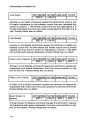
PROGRAMMER INFORMATION
Line Insert
QYT-102/1 02A HZ-1500 ADM-3A/5 TVI-910
rvCtrl-Z
ESC E
Issuing a Line Insert command causes the terminal to insert a line
of space characters on the present cursor line and relocates the
cursor to column 1. The former cursor line and any data below it is
moved downward one line; any data moved beyond the 24th line is
lost. Protect Mode has no affect.
Line Delete
QYT-102/1 02A HZ-1500 ADM-3A/5 TVI-910
rvCtrl-S
ESC R
Issuing a Line Delete command causes the terminal to delete the
present cursor line. All data below the former cursor line is moved
upward one line and the cursor is relocated to column 1. The 24th
line is filled with space characters. Protect Mode has no affect.
Clear Line to Spaces
QYT-102/102A HZ-1500 ADM-3A/5 TVI-910
rvCtrl-O
ESCT
ESCT
ESCT
A Clear Line to Spaces command causes the terminal to replace all
characters with space characters, from the cursor position to the
end of the line. Protect Mode has no affect.
Clear Line to Nulls
QYT-102/1 02A HZ-1500 ADM-3A/5 TVI-910
ESC t
A Clear Line to Nulls command causes the terminal to replace all
characters with nulls, from the cursor position to the end of the line.
Protect Mode has no affect.
Clear Screen to
Spaces
QYT-102/102A HZ-1500 ADM-3A/5 TVI-910
rvCtrl-X
ESCY
ESCY
ESCY
A Clear Screen to Spaces command causes the terminal to replace
all characters with space characters, from the cursor position to the
end of the screen. Protect Mode has no affect.
4-14
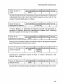
PROGRAMMER INFORMATION
Clear Screen to
Nulls
QVT-1 0211 02A HZ-1500 ADM-3A/5 TVI-910
ESC y
A Clear Screen to Nulls command causes the terminal to replace all
characters with nulls, from the cursor position to the end of the
screen. Protect Mode has no affect.
Clear Screen to
Background Spaces
QVT-1 0211 02A HZ-1500 ADM-3A/5 TVI-910
rvCtrl-w
A Clear Screen to Background Spaces causes the terminal to
replace all display data with background spaces (half intensity)
from the cursor to the end of the screen.
Clear All to
Background Spaces
QVT-1 0211 02A HZ-1500 ADM-3A/5 TVI-910
ESC,
Issuing this command clears all display data to background spaces
(half intensity) and homes the cursor.
Clear All Foreground
Area to Spaces
I
I
I
I
QVT-1 0211 02A HZ-1500 ADM-3A/5 TVI-910
rvCtlShft-M
ESC;
rvCtrl-]
Issuing this command clears all data to space characters and
homes the cursor.
Clear All Foreground
Area to Nulls
QVT-1 0211 02A HZ-1500 ADM-3A/5 TVI-910
ESC:
Issuing this command clears all data to nulls and homes the cursor.
4·15
PROGRAMMER INFORMATION
Clear Screen to
Spaces
QVT-102l102A HZ-1500 ADM-3A/5 TVI-910
Ctrl-Z
Ctrl-Z
Ctrl-Z
"-'Ctrl-\
"-'Ctl-Shft-L
ESC +
ESC +
I
-.
Depressing the Shift and Clear Home keys or issuing a Clear Screen
to Spaces command, clears all screen data to space characters and
homes the cursor.
Clear Screen to
Nulls
QVT-1 0211 02A HZ-1500 ADM-3A/5 TVI-910
ESC *
ESC *
Issuing a Clear Screen to Nulls command, clears all screen data to
nulls and homes the cursor.
SEND FUNCTION
Data may be transmitted to the host computer by either depressing
the Enter key (QVT-102/QVT-102A only) or by issuing a specific send
command to transmit a select string of data. Each of these send options is described below. See also "Transmission Modes" later in
this section, and "Transmitting (Sending) the Screen Display to the
Host Computer" in the section entitled OPERATION.
Send Line (Full
Intensity Only)
QVT-1 0211 02A HZ-1500 ADM-3A/5 TVI-910
ESC 4
Issuing this command causes all full intensity data in a given cursor
line to be transmitted to the host computer..
Send Page (Full
Intensity Only)
QVT-102/102A HZ-1500 ADM-3A/5 TVI-910
ESC 5
Issuing this command causes all full intensity data on the display
screen to be transmitted to the host computer.
Send Line (All)
QVT-102l102A HZ-1500 ADM-3A/5 TVI-910
ESC 6
Issuing this command causes all data on a given cursor line to be
transmitted to the host computer.
4-16
PROGRAMMER INFORMATION
Send Page (All)
QVT-102/102A HZ-1500 ADM-3A/5 TVI-910
ESC 7
Issuing this command causes all data on the display screen to be
transmitted to the host computer.
Send ID Message
QVT-102/1 02A HZ-1500 ADM.-3A/5 TVI-910
Ctrl-E
Ctrl-E
Issuing this command transmits the HERE IS Message entered on
the Status Line to the host computer.
Program Send
Delimiter
QVT-102/102A HZ-1500 ADM-3A/5 TVI-910
ESC x N
This command specifies the End of Message character that terminates each data transmission. In the code sequence, "N" equals
the ASCII code for the delimiter desired. Possible values may be a
NUL, ETX, EOT, or a CR.
PRINT FUNCTION
Data is output from the terminal to the printer via the AUX (Auxiliary)
Port. The AUX Port on the QVT-102 is capable·of supporting only
unidirectional communication; whereas, the QVT- 102A can support
bidirectional communications. Both honor X- ON/X-OFF and/or DTR
protocol, and comply with the EIA Rs-232-C standard. The various
print functions and their command sequences are described below.
Print from Top of
Screen to Cursor
QVT-102/1 02A HZ-1500 ADM-3A/5 TVI-910
ESC N
Depressing the Shift and Print keys, or issuing a Print from Top of
Screen to Cursor command causes the terminal to transmit all
screen data from the Home position to the cursor, to the printer.
4-17
PROGRAMMER INFORMATION
Print from Cursor
to End of Screen
QVT-1 0211 02A HZ-1500 ADM-3A/5 TVI-910
ESC a
Depressing the Ctrl and Print keys, or issuing a Print from Cursor to
End of Screen command causes the terminal to transmit all screen
data from the cursor position to the end of the screen, to the printer.
Print Entire Page
QVT-102l102A HZ-1500 ADM-3A/5 TVI-910
ESC P
Depressing the Print key or issuing a Print Entire Page command
causes the terminal to transmit all screen data to the printer.
Transparent Mode
Enable
QVT-1 0211 02A HZ-1500 ADM-3A/5 TVI-910
Ctrl-R
Ctrl-R
Issuing a Transparent Mode Enable command causes the terminal
to bypass all data received (including control characters) and output it via the Auxiliary Port. No screen updating can occur while
Transparent Print Mode is enabled.
Transparent Mode
Disable
QVT-102l102A HZ-1500 ADM-3A/5 TVI-910
Ctrl-T
Ctrl-T
Issuing a Transparent Mode Disable command disables the
Transparent Print Mode after all data remaining in the Auxiliary Port
buffer has been output.
AUX Port Enable
QVT-1 0211 02A HZ-1500 ADM-3A/5 TVI-910
Ctrl-N
ESC @
ESC @
Issuing an AUX Port Enable command functionally connects the
AUX Port to the EIA Port to enable the terminal to output all data
received from either the host or the keyboard, to the peripheral
(printer) connected to the AUX Port. The QVT-102A is equipped with
a bidirectioinal AUX Port.
4-18
PROGRAMMER INFORMATION
AUX Port Disable
QVT-1 0211 02A HZ-1500 ADM-3A/5 TVI-910
ESC A
Ctrl-O
ESC A
Issuing an AUX Port Disable command functionally disconnects the
EIA and AUX Ports.
VIDEO ATTRIBUTES
A video attribute can be classified as either a screen, fieldlline, or
character attribute depending on the way it affects the display.
Each of these classifications is described below.
SCREEN ATTRIBUTES
Screen attributes affect all areas on the display screen. This kind of
attribute is not embedded and therefore does not occupy a
character position on the screen.
Cursor Visible/
Invisible
QVT-1 0211 02A HZ-1500 ADM-3A/5 TVI-910
ESC.
ESC.
The Cursor Visible/Invisible command is an On/Off feature that
allows the cursor to be selectively displayed or blanked from screen
display.
FIELD/LINE ATTRIBUTES
Field/line attributes affect all or part of a given display line. Such attributes are embedded (Le., they occupy a character position on the
screen) and appear as a space that displays with the same attribute
they specify. All characters on a line following a fieldlline attribute
will exhibit the characteristics of that attribute until a new attribute
is specified or until the 80th column is reached. Fieldlline attributes
do not carryover to the next line.
Blank
QVT-1 0211 02A HZ-1500 ADM-3A/5 TVI-910
ESC G 1
ESC G 1
Blank is a video attribute that is visualized as a space character(s).
Issuing this command causes all character positions from the cursor to the end of a field or line to be suppressed or blanked from
screen display.
4-19
PROGRAMMER INFORMATION
Blink
QVT-102/1 02A HZ-1500 ADM-3A15 TVI-910
ESC G 2
ESC G 2
Blink is a video attribute that causes all character positions displaying data from the cursor position to the end of a field or line to blink
synchronously.
Invisible/Blink
QVT-1 02/1 02A HZ-1500 ADM-3A/5 TVI-910
ESCG 3
ESC G 3
Invisible/Blink combines the characteristics of the Blank and Blink
video attributes. All data entered from the cursor position to the end
of a field or line is suppressed or blanked from video display. The
blink attribute is not apparent.
Reverse Video
QVT-102/102A HZ-1500 ADM-3A/5 TVI-910
ESCG 4
ESCG ESC G 4
Reverse Video is a field/line attribute that causes all character p·ositions displaying data from the cursor position to the end of the field
or line to be visualized as dark characters on a light background; the
opposite of the default power On video display condition.
Invisible/Reverse
QVT-102/102A HZ-1500 ADM-3A15 TVI-910
ESCG 5
ESC G 5
Invisible/Reverse combines the characteristics of the Blank and
Reverse Video attributes. When this combination attribute is
selected, it is visualized as a blank, reverse video field or line
originating from the cursor position.
Reverse/Bli nk
QVT-102/1 02A HZ-1500 ADM-3A15 TVI-910
ESCG 6
ESC G 6
Reverse/Blink combines the characteristics of the Blink and
Reverse Video attributes. When this combination attribute is
selected, it is visualized as a reverse video field or line originating
from the cursor position. Data entered after this attribute blinks synchronously.
4·20
PROGRAMMER INFORMATION
Invisible/Reverse/
Blink
QVT-1 0211 02A HZ-1500 ADM-3A/5 TVI-910
ESCG 7
ESC G 7
Invisible/Reverse/Blink combines the characteristics of the Blank,
Reverse Video, and Blink attributes. When this combination attribute is selected it is visualized as a reverse video field or line
originating from the cursor position. Data entered after this attribute is blanked from screen display; the blink attribute is not apparent.
Underline
QVT-102l102A HZ-1500 ADM-3A/5 TVI-910
ESC G 8
ESC G 8
Underline is a video attribute that causes all character positions
from the cursor to the end of a field or line to display as underlined.
Invisible/Underline
QVT-102l102A HZ-1500 ADM-3A/5 TVI-910
ESC.G 9
ESC G 9
Invisible/Underline combines the Blank and Underline video attributes. When this combination attribute is selected, it is visualized
as an underlined field or line originating from the cursor position.
Data entered after this attribute is blanked from screen display.
Normal Video
QVT-10211 02A HZ-1500 ADM-3A/5 TVI-910
ESCG ESC GO
ESC G 0
Normal Video is a fieldlline attribute that causes all character positions displaying data from the cursor position to the end of the field
or line to be visualized as light characters on a dark background; the
opposite of the Reverse Video field/line attribute.
Blink/Underline
QVT-10211 02A HZ-1500 ADM-3A15 TVI-910
ESCG:
ESC G:
Blink/Underline combines the Blink and Underline video attributes.
When this combination attribute is selected, it is visualized as an
underlined field or line originating from the cursor position. Data
entered after this attribute blinks synchronously.
4·21
PROGRAMMER INFORMATION
Invisible/Blinkl
Underline
QVT-1 0211 02A HZ-1500 ADM-3A/5 TVI-910
ESC G;
ESC G;
Invisible/BlinklUnderline combines the Blank, Blink, and Underline
video attributes. When this combination attribute is selected, it is
visualized as an underlined field or line originating from the cursor
position. Data entered after this attribute is blanked from screen
display; the underline attribute is not apparent since it defines the
bottom edge of the reverse video area.
Invisible/Reverse
BlinklUnderline
QVT-1 0211 02A HZ-1500 ADM-3A/5 TVI-910
ESC G?
ESC G?
Invisible/Reverse/BlinklUnderline combines the Blank, Reverse
Video, Blink, and Underline video attributes. When this combination
attribute is selected, it is visualized as a reverse video field or line
originating from the cursor position. Data entered after this attribute is blanked from screen display; the underline and blink attri butes are not apparent.
Invisi ble/Reverse/
Underline
QVT-1 0211 02A HZ-1500
ESC G
=
ADM-3A~
TVI-910
ESC G
=
Invisible/Reverse/Underline combines the Blank, Reverse Video,
and Underline video attributes. When this combination attribute is
selected, it is visualized as reverse video field or line originating
from the cursor position. Data entered after this attribute is blanked
from screen display; the underline attribute is not apparent since it
defines the bottom edge of the reverse video area.
Reverse/U nderl i ne
QVT-102l102A HZ-1500 ADM-3A/5 TVI-910
ESC G <
ESC G <'
Reverse/Underline combines the Reverse and Underline video attributes. When this combination attribute is selected, it is visualized
as a reverse video field or line originating from the cursor position.
Data entered after this attribute displays in reverse video; the
underline attribute is not apparent since it defines the bottom edge
of the reverse video field.
4-22
PROGRAMMER INFORMATION
Reverse/Blink/
Underline
QVT·102l102A HZ·1500 ADM·3A/5 TVI·910
ESC G >
ESC G>
Reverse/Blink/Underline combines the Reverse Video, Blink, and
Underline video attributes. When this combination attribute is
selected, it is visualized as a reverse video field or line originating
from the cursor position. Data entered after this attribute blinks syn·
chronously; the underline attribute is not apparent since it defines
the bottom edge of the reverse video field.
CHARACTER ATTRIBUTES
Character attributes affect characters as they are entered on the
screen and like screen attributes, they are not embedded (Le., they
do not occupy a character position on the screen). Character at·
tributes may exist along with any other screen or fieldlline at·
tributes already specified. Any new character entered while a given
character attribute is in effect will display with that attribute
regardless of its position on the screen.
Full Intensity
QVT·1 0211 02A HZ·1500 ~ ADM·3A/5 TVI·910
(Foreground Follows)
ESC (
~Ctrl·_1
ESC (
ESC (
~CUShft.()
All data entered after this video attribute is selected will display in
full video intensity. Full intensity is the normal display intensity at
initial power On.
Half Intensity
QVT·1021102A HZ·1500 ADM·3A/5 TVI·910
(Background Follows)
ESC)
~Ctrl·Y
ESC)
ESC)
All data entered after this video attribute is selected will display in
half the normal video intensity. Data displayed in half intensity can
be protected by enabling Protect Mode.
4·23
PROGRAMMER INFORMATION
PROTECT MODE
Protect Mode is a feature that allows selected areas of the display
to be protected from accidental overwriting. The commands that
control Protect Mode are discribed below.
Protect Mode Enable
QVT-102/102A HZ-1500 ADM-3A/5 TVI-910
ESC &
Issuing this command causes the terminal to interpret all h~alf intensity fields, including any attributes within these fields, as protected
areas within which data can not be ovewritten. Attempting to enter
data into a protected area will sound the alarm and the cursor will
be moved to the first unprotected character position beyond the
protected area; here, subsequent data will display as it is entered.
Protect Mode Disable QVT-1 0211 02A HZ-1500 ADM-3A/5 TVI-910
ESC'
Issuing this command disables the Protect Mode feature.
TRANSMISSON MODES
Transmission Mode can be selected from either the status line or by
command code sequence. See also "Send Function" earlier in this
section, and the paragraph "Transmitting (Sending) the Screen
Display to the Host Computer" in the section entitled OPERATION.
Block Mode Enable
QVT-1 0211 02A HZ-1500 ADM-3A/5 TVI-910
ESC B
Block Mode configures the terminal for page-by-page data
transmission. In Block Mode, only unprotected data will be
transmitted to the host computer when the Enter key is depressed
(blank areas are transmitted as spaces; no end of line message is
transmitted). A Block Mode transmission is a 1,920 character string
(maximum) that is terminated by the End of Message code selected
on the Status Line. The Program Function keys do not operate in
this mode.
4-24
PROGRAMMER INFORMATION
Character Mode
Enable
QVT-1 0211 02A HZ-1500 ADM-3A/5 TVI-910
ESC C
Character Mode configures the terminal for conversational or
character-by-character data transmission. Each character keyed
from the keyboard is immediately transmitted to the host.
Line Mode Enable
QVT-1 0211 02A HZ-1500 ADM-3A/5 TVI-910
ESC D
Line Mode configures the terminal for line-by-line data transmission. In Line Mode, only unprotected data on a given cursor line will
be transmitted to the host computer when the Enter key is depressed (blank areas are transmitted as spaces). A Line Mode transmission is terminated by the End of Message code selected on the
Status Line. The Program Function keys do not operate in the
mode.
GRAPHICS MODE
Graphics Mode is a special applications feature that reconfigures
the terminal for 15 line drawing symbols (refer to Table 4-4).
Graphics Mode is controlled by the following command sequences.
Graphics Mode
Enable
QVT-1 0211 02A HZ-1500 ADM-3A/5 TVI-910
ESC $
Issuing this command configures the terminal for Graphics Mode
by redefining the A through 0 alphabetic keys for a special set of
line drawing characters. For proper operation the Caps Lock key
should be disengaged.
Graphics Mode
Disable
QVT-1 0211 02A HZ-1500 ADM-3A/5 TVI-910
ESC 0/0
Issuing this command exits the Graphics Mode; keys A through
function as alphabetic character keys.
a
4-25
PROGRAMMER INFORMATION
Table 4·4. Special Graphics Mode Characters
Key
Graphics Character
a
l
b
(
c
d
I
J
e
L
f
I
9
l
h
J
i
+
I
j
k
-
I
-i
m
~
n
T
1
0
4-26
PROGRAMMER INFORMATION
MISCELLANEOUS PROGRAM FUNCTIONS
KEYBOARDLOC~UNLOCK
Keyboard Disable
QVT-1 0211 02A HZ-1500 ADM-3A/5 TVI-910
ESC #
Ctrl-O
ESC #
"-'Ctrl-U
Issuing this command disables the keyboard except for the Setup,
Print, Break, Ctrl, and Shift keys. This feature is also available as a
status line selection. Manual override can be accomplished by performing a reset; i.e., depressing the CtrllShiftlSetup-Setup keys
(QVT-102A only; depress Setup-Setup for QVT-102), or the Shift and
Break keys (QVT-102A and QVT-102).
Keyboard Enable
QVT-102l102A HZ-1500 ADM-3A/5 TVI-910
"-'Ctrl-F
Ctrl-N
ESC"
ESC"
This command restores the action of the keyboard and can only be
issued from the host computer. Locally, the keyboard can be
restored by depressing the Ctrl/Shift/Setup-Setup keys (QVT-102A
only; depress Setup-Setup for QVT-102), or the Shift and Break keys
(QVT-102A and QVT-102).
AUTO SCROLL ENABLE/DISABLE
Auto Scroll Enable/
Disable
QVT-1 0211 02A HZ-1500 ADM-3A/5 TVI-910
ESC H
ESC H
The Scroll Enable/Disable feature is an On/Off feature that can be
used to control the automatic scrolling of the screen display.
RING BELL
Ring Bell
QVT-1 0211 02A HZ-1500 ADM-3A/5 TVI-910
Ctrl-G
Ctrl-G
Ctrl-G
Ctrl-G
Issuing this command causes the audible alarm to sound.
4-27
PROGRAMMER INFORMATION
STATUS LINE DISPLAY/BLANK
Display Status Line
QVT-102J102A HZ-1500 ADM-3A/5 TVI-910
ESC}
ESC}
ESC}
"'Ctrl-P
Issuing this command causes the terminal to display the status line
on the 25th line.
Blank Status Line
QVT-1 0211 02A HZ-1500 ADM-3A/5 TVI-910
ESC {
ESC {
ESC {
"'Ctrl-N
Issuing this command blanks the display of the status line on the
25th line.
SELF-TEST DISPLAY/BLANK
Self-Test Display
QVT-102J102A HZ-1500 ADM-3A/5 TVI-910
ESC V
ESC V
Issuing this command causes the terminal to display its entire complement of control codes, graphics characters, and video attributes
as a visual self-test.
Self-Test Blank
QVT-1 02/1 02A HZ-1500 ADM-3A/51 TVI-910
~hftlBreakShftlBreakShftlClear
IShftlClear
Depressing the Shift and Break keys followed by the Shift and Clear
Home keys causes the terminal to clear the current display page to
space characters and home the cursor.
4·28
PROGRAMMER INFORMATION
"H" VIDEO ALIGNMENT PATTERN DISPLAY/BLANK
"H" Pattern Display
OVT-102l102A1 HZ-15001 ADM-3A/51 TVI-910
Ctrl/Shift/Setup 0
Depressing the Ctrl/Shift/Setup keys followed by the Zero key (OVT102A only; depress Setup-Zero for OVT-102) causes the terminal to
display a 24 line by 80 column "H" video alignment pattern.
Centered within this display is a series of numbers that identifies
the terminal's firmware revision level.
"H" Pattern Blank
I
OVJ-102l102A1 HZ-1500 ADM-3A/51 TVI-910
Shift/Clear Home
Depressing the Shift and Clear Home keys causes the terminal to
clear the "H" pattern display to space characters and home the
cursor.
4·29
SECTION 5.
OPERATOR CARE
Operator care of the QVT-102/QVT-102A is limited to keeping both
the display module and keyboard clean and free of dust. Occasionally use a soft brush or vacuum cleaner to remove any accumulated dust.
Use a commercially available cleaning kit for care of the display
screen and more stubborn cleaning requirements. Before cleaning
the display screen always power OFF the terminal.
In some environments, it may be beneficial to protect the terminal
with a dust cover when it is not in use.
5-1
SECTION 6.
GLOSSARY
INTRODUCTION
This glossary of terms is provided as a helpful aid to a better
understanding of the terminal and its environment.
ASCII
Acronym for the American Standard Code for Information Interchange. A standardized code for the transmission of data, composed of 128 characters (upper-and lower-case letters, numbers,
punctuation marks, symbols, and control characters) represented in
7-bit binary format.
Baud Rate
The rate of data transmission. One baud represents a transmission
rate of one binary bit of data per second.
Break
A communications interrupt signal used to immediately halt communications.
Command
A special code, or series of codes, that causes the terminal or host
computer to perform a specific electronic or mechanical action.
Commands are generated in conjunction with the Control or
Escape keys (or the tilde (f\.I) key when the Hazeltine 1500 emulation
is selected). Such commands are n~n-printable, e.g., setting a tab.
Cursor
A highlighted area (underline or block) that is used on the display
screen to indicate the next character position.
Data
A general term used to describe that which is transmitted. Data is
both ASCII encoded alphanumeric characters and command instructions.
fl-1
GLOSSARY
Del (Delete)
An ASCII code used to delete or cancel transmitted data.
EIA RS·232·C
The Electronic Industries Association that sets forth standards for
electronic and electrical devices. Your terminal complies with the
EIA RS-232-C Standard for communicating devices.
Emulation
The act of imitating a device as if it were that device. Your terminal
emulates three other video terminals in addition to its own performance criteria.
Handshaking
A communications method that controls the flow of data transmission. This is necessary when the speed of data handling varies between the devices within the system. Three methods of handshaking are available for use with your terminal: X-ON/X-OFF (Transmit
OnlTransmit Off) with DTR (Data Terminal Ready), X- ON/X-OFF only, or DTR only.
Home
Home is that position on the display screen identified as Line 1,
. Column 1.
Host or Host Computer
The computer that controls the system of which the terminal is a
part.
Interface (AUX and EIA)
The communications channel through which data flows; both the
physical connectors and the signal lines.
Nul (Null)
An ASCII code that is used as a fill character in some communications formats (a nothing character).
Parity
A method of checking for errors in data communications.
6·2
GLOSSARY
Reverse Video
That condition of the video screen in which data is displayed as
dark characters on a light background. Reverse video is the opposite of normal or standard video.
Screen
Literally the word "screen" is synonymous with "display screen"
and "video display," but in actual usage is often used interchangeably with "page."
Scroll
As all 24 lines of the display screen are filled with data, the screen is
said to "scroll" when the first line disappears, and the display
moves up one line to vacate the bottom line for new data. If this
feature is disabled, as the 24th line is completed, the cursor will
move to line 1, column 1 and the display will be overwritten as
subsequent data is entered.
Terminal
An electronic communicating device that is generally considered to
have the capability to transmit and receive data. Some terminals are
used as receive only devices.
Toggle
To select a function, or enable or disable a function, by depressing
a key. In this terminal, the fields in the status lines are toggled by
the space bar.
Wraparound
An automatic carriage return, line feed operation. The action of the
cursor as it reaches the end of a line and then automatically goes to
the beginning of the next line.
6-~
SECTION A.
APPENDIX
The following appendices are provided for reference.
Appendix
A
B
C
D
E
F
EIAIAUX Connector Pinout Descriptions
Interface Jumpers Description
Errors Code Summary
US ASCII Code Chart
Control Code Keystrokes
Command Set Summary
A.1
APPENDIX
Appendix A. EIAIAUX Connector Pinout Descriptions
EIA· Main Port Interface Connector Pinout Description
Pin No. Signal Description
1
2
3
4
5
6
7
8
12
13
20
24
25
Protective Ground
Transm itted Data
Received Data
Request to Send
Clear to Send
Data Set Ready
Signal Ground
Data Carrier Detect
Current Loop-RXD( + )
Current Loop-TXD( - )
Data Terminal Ready
Current Loop-RXD( - )
Current Loop-TXD( + )
Signal Direction
Designation
----
AA
SA
SS
CA
CS
CC
AS
CF
From Terminal
To Terminal
From Terminal
To Terminal
To Terminal
---To Terminal
-------
From Terminal
CD
----
----
AUX·Auxiliary Port Interface Connector Pinout Description
Pin No Signal Description
1
2
3
6
7
20
A-2
Protective Ground
Transmitted Data
(QVT-102A Only)
Received Data
Data Set Ready
Signal Ground
Data Terminal Ready
Signal Direction
---To Terminal
From Term i nal
To Terminal
---From Terminal
Designation
AA
SA
SS
CC
AS
CD
APPENDIX
Appendix B. Interface Jumpers Description
EIA RS·232·C Interface Jumper Placement
Jumper
Description
STANDARD: W21nstalled Data Carrier Detect (DCD) - Input
signal to the terminal used to monitor
the readiness status of an external
modem.
W3 Installed Data Terminal Ready (DTR) - Output
signal from the terminal to the host
used to enable communications.
OPTION:
W1 Installed Data Set Ready (DSR) - Input signal to
the terminal that may be used instead
of Data Carrier Detect to monitor the
readiness status of an external
modem.
W4 Installed Request to Send (RTS) -Output signal
from the terminal to the host that may
be used instead of Data Terminal
Ready to enable communications.
Current Loop Interface Jumper Placement *
Jumper
Active Mode
Passive Mode
W5
W6
W7
W8
W9
W10
W11
W12
W13
W14
In
Out
In
In
Out
Out
In
In
Out
In
Out
In
Out
Out
In
In
Out
Out
In
Out
* Additional Factory Installed Current Loop Components Required.
A-3
APPENDIX
Appendix C. Error Codes Summary
When the terminal is powered On, a self-test is automatically performed. If a non-fatal error is detected, an error code will be
displayed on the screen. For example, if the letter "D" is displayed,
this signifies that an error exists in the video RAM circuit.
Error Code
Character Displayed
SROM
A
*
B
*
C
Fault Detected Item
VRAM
SRAM
*
*
D
*
E
F
G
H
I
*
*
J
K
*
L
M
*
N
A-4
*
*
*
*
*
*
*
*
0
Legend:
KBD
=
=
=
*
*
*
*
*
*
*
*
*
*
*
*
*
*
*
SROM
System ROM (Read Only Memory)
SRAM
System RAM (Random Access Memory)
VRAM = Video RAM
KBD
Keyboard
APPENDIX
Appendix D. US ASCII Code Chart
••
b7
~~
B.
I
t
bs
b4
s
00
•
~
0 0 0 0
b3
b2
b1
0
0
0
1
1
1
1
0
0
0
0
1
1
1
1
0
1
1
0
0
1
1
0
0
1
1
0
0
1
1
1
0
1
0
1
0
1
0
1
0
1
0
1
0
1
00
0
1
1
0
o1
1
10
0
10
1
11
11
1
0
0
1
2
3
4
5
NUL
DLE
SP
0
@
P
\
1
SOH
DC1
!
1
A
Q
a
2
3
4
5
6
STX
DC2
"
2
B
R
b
r
ETX
DC3
#
3
C
S
c
s
Row . .
0
0
0
0
0
0
0
0
1
1
1
1
1
1
1
1
0
6
7
P
q
EOT
DC4
$
4
D
T
d
t
ENG
NAK
%
5
E
U
e
u
ACK
SYN
&
6
F
V
f
v
7
BEL
ETB
7
G
W
9
w
8
BS
CAN
(
8
H
X
h
x
9
HT
EM
)
1
Y
i
Y
A
LF
SUB
.
9
J
Z
j
z
8
C
D
VT
ESC
+
K
[
k
{
FF
FS
CR
GS
E
so
RS
F
SI
us
\.
-
/
<
L
\
1
I
=
M
J
m
}
>
N
A
n
-
?
0
-
0
DEL
A
./
~~------~..-------
32 ASCII
Control Codes
Notes: • Hexadecimal
96 ASCII Character Set
= ASCII Column
+ Row. A
= 41
Hex
• Example: ASCII Encoded Letter A = Bits: P 7 6 5 4 321
*1000001
(* = Parity Bit)
• In the German character set, the Scharfes S occupies
the same character position in the ASCII Code Chart
as the tilde (I'\.J) character. When using the terminal in
the HZ-1500 emulation, do not use the Scharfes S in
text as it will be interpreted as the Hazeltine lead-in
character.
A-5
APPENDIX
, Appendix E. Control Code Keystrokes
The following table lists the keystrokes necessary for generating
the 32 possible ASCII control codes. Control codes are issued by
depressing the Control key simultaneously with another key as
follows:
Keystroke
ASCII
Control Hex Description
Code
Control Key Depressed
with Additional Key(s)
NUL
SOH
STX
ETX
EOT
ENQ
ACK
BEL
BS
HT
LF
VT
FF
CR
SO
SI
DLE
DC1
DC2
DC3
DC4
NAK
OA
OB
OC
OD
OE
OF
10
11
12
13
14
15
Control-@
Control-A
Control-B
Control-C
Control-D
Control-E
Control-F
Control-G
Control-H
Control-I
Control-J
Control-K
Control-L
Control-M
Control-N
Control-O
Control-P
Control-Q
Control-R
Control-S
Control-T
SYN
ETB
16
17
CAN
EM
SUB
18
19
1A
A·6
00
01
02
03
04
05
06
07
08
09
Null
Start of Header
Start of Text
End of Text
End of Transmission
Enquiry
Acknowledge
Bell
Backspace
Horizontal Tab
Line Feed
Vertical Tab
Form Feed
Carriage Return
Shift Out
Shift In
Data Li ne Escape
Device Control 1
Device Control 2
Device Control 3
Device Control 4
Negative
Acknowledge
Synchronous Idle
End of Transmission
Block
Cancel
End of Medium
Substitute
Dis·
play·
@
A
~
.Q
Q
..E.
F
§
1:!.
_I
..J.
.K.
l
M.
li
Q
E
Q
J1
~
l.
Control-U
Control-V
..u.
Control-W
Control-X
Control-Y
Control-Z
W
jl
X
Y
Z
APPENDIX
Appendix E. Control Code Keystrokes (cont)
ASCII
Keystroke
Control Hex Description
Code
Control Key Depressed
with Additional Key(s)
ESC
FS
GS
RS
US
ESC
Control-\ or Control-Shift~
Control-] or Control-Shift-M
Control-t\ or Control-Shift-N
Control--_ or Control-Shift-O
18
1C
1D
1E
1F
Escape
Fi Ie Separator
Group Separator
Record Separator
Unit Separator
Dis·
play*
[
"\
-]
A
--
* If Monitor Mode is enabled, control codes will display as an underlined letter. For example, a CR control code, or carriage return, will
display as an underlined capital M (Le., M).
A·7
»
""C
Appendix F. Command Set Summary
""C
m
z
o
Command/Key
Function
QVT·1 02lQVT·1 02A
HZ·1500
ADM·3A15
x
TVI·910
Cursor
Home
Right
Left
Up
Down
Return
New Line
Ctrl-J\
HOME
Ctrl-L
RIGHT ARROW
SHIFT/BS
Ctrl-H
LEFT ARROW
BACKSPACE
Ctrl-K
UP ARROW
SHIFT/LF
Ctrl-J
DOWN ARROW
LlNEFEED
Ctrl-M
RETURN
ENTER
Ctrl-_
"-'Ctrl-R
HOME
Ctrl-P
RIGHT ARROW
SHIFT/BS
Ctrl-H
LEFT ARROW
BACKSPACE
"-'Ctrl-L
UP ARROW
SHIFT/LF
"-'Ctrl-K
Ctrl-J
DOWN ARROW
LlNEFEED
Ctrl-M
RETURN
ENTER
Ctrl-J\
HOME
Ctrl-L
RIGHT ARROW
SHIFT/BS
Ctrl-H
LEFT ARROW
BACKSPACE
Ctrl-K
UP ARROW
SHIFT/LF
Ctrl-J
DOWN ARROW
LlNEFEED
Ctrl-J\
HOME
Ctrl-L
RIGHT ARROW
SHIFT/BS
Ctrl-H
LEFT ARROW
BACKSPACE
Ctrl-K
UP ARROW
SHIFT/LF
Ctrl-J
DOWN ARROW
LlNEFEED
Ctrl-M
RETURN
ENTER
Ctrl-M
RETURN
ENTER
Ctrl-_
Appendix F. Command Set Summary (cont)
Command/Key
Function
QVT·102lQVT·102A
HZ·1500
ADM·3A15
TVI·910
Tab Control
Set Tab
Clear Tab
Clear All Tabs
Column Tab
Field Tab
Back Tab
ESC 1
ESC 2
ESC 3
Ctrl-I
TAB
Ctrl-I IProtectl
TAB IMode Onlyl
ESC I
SHIFTITAB
ESC 1
ESC 2
ESC 3
Ctrl-I
TAB
Ctrl-I
TAB
ESC I
SHIFTITAB
Editing Functions
Character Insert
Character Delete
Line Insert
Line Delete
Clear from cursor to
end of line with
spaces
ESC Q
ESCW
ESC E
ESC R
ESCT
rvCtrl-Z
rvCtrl-S
rvCtrl-O
ESC T
ESCT
»"'tJ
"'tJ
m
Z
o
X
»
Appendix F. Command Set Summary (cont)
"'tJ
"'tJ
m
z
Command/Key
Function
QVT·102lQVT·102A
HZ·1500
ADM·3A15
c
TVI·910
Editing Functions (cont)
Clear from cursor to
end of line with
nulls
Clear from cursor to
end of screen with
spaces
Clear from cursor to
end of screen with
nulls
Clear from cursor to
end of screen with
background spaces
Clear all to
background spaces
Clear all foreground
area to spaces
Clear all foreground
area to nulls
ESC t
ESCY
rvCtrl-X
ESCy
rvCtrl-w
ESC,
ESC;
ESC:
rvCtrl-SH IFT-M
rvCtrl-]
ESCY
ESCY
x
Appendix F. Command Set Summary (cont)
Command/Key
Function
QVT·102lQVT·102A
HZ·1500
ADM·3A15
TVI·910
Editing Functions (cont)
Clear screen to
nulls
Clear Screen
ESC *
Ctrl-Z
ESC +
SH 1FT/CLEAR
ESC *
"'Ctrl-\
"'Ctrl-SH IFT-L
SHIFT/CLEAR
Ctrl-Z
SH 1FT/CLEAR
Ctrl-Z
ESC +
SHIFT/CLEAR
Video Attributes
Screen Attributes:
Cursor Visiblellnvisible ESC.
ESC.
Field/Line Attributes:
Blank
Blink
Invisi bie/Bli n k
ESC G 1
ESC G 2
ESC G 3
ESC G 1
ESC G 2
ESC G 3
»
-u
"U
m
z
o
X
»
"0
Appendix F. Command Set Summary (cont)
"0
m
Z
Command/Key
Function
QVT-102lQVT-102A
HZ·1500
o
X
ADM-3A15
TVI-910
Field/Line Attributes (cont)
ESC G 4
Reverse Video
Invisible/Reverse
ESC G 5
Reverse/Blink
ESC G 6
Invisible/Reverse/Blink ESC G 7
ESC G 8
Underline
Invisible/Underline
ESC G 9
Normal Video
ESC GO
Blink/Underline
ESC G:
Invisible/Blink!Underline ESC G ;
Invisible/Reverse/Blink! ESC G ?
Underline
Invisible/Reverse/
ESC G
Underline
Reverse/Underl i ne
ESCG<
Reverse/Blink!Underline ESC G >
ESC G
~
,
Enable/
Disable
Feature
ESCG
=
Character Attributes:
I
Full Intensity
ESC (
(foreground follows)
Half Intensity
I ESC)
(background follows)
I
ESC G 4
ESC G 5
ESC G 6
ESC G 7
ESC G 8
ESC G 9
ESC G 0
ESCG:
ESC G;
ESC G?
ESC G
=
ESC G<
ESC G >
I'\JCtrl-_
I'\JCtrl-SHIFT 0
I'\JCtrl-Y
ESC (
ESC (
ESC)
ESC)
Appendix F. Command Set Summary (cont)
Command/Key
Function
QVT·102lQVT·102A
HZ·1S00
ESC #
ESC" (Host*)
SHIFT/BREAK
CTRUSHIFT/
SETUP-SETUP
SETUP-SETUP
ESC = Line #
Col #
ESC?
ESC [ Line #
ESC] Col #
Ctrl-R
"-ICtrl-U
"-ICtrl-F (Host *)
SHIFT/BREAK
CTRUSHIFT
SETU P-SETU P
SETUP-SETUP
"-ICtrl-Q Col #
Line #
"-ICtrl-E
ADM·3A1S
TVI·91 0
Program Functions
Keyboard Disable
Keyboard Enable
(QVT-102A Only)
(QVT-102 Only)
Address Cursor
Read Cursor Address
Load Cursor Line
Load Cursor Column
Transparent Mode
Enable
Transparent Mode
Disable
AUX Port Enable
AUX Port Disable
Graphics Mode Enable
Graphics Mode Disable
Monitor Mode Enable
I
Ctrl-O
Ctrl-N (Host *)
SHIFT/BREAK
CTRUSHIFT
SETUP-SETUP
SETUP-SETUP
ESC = Line #
Col #
Ctrl-T
Ctrl-T
ESC @
ESC A
ESC $
ESC 0/0
ESC U
Ctrl-1
*This command is functional only from the Host.
ESC #
ESC " (Host *)
SHIFT/BREAK
CTRUSHIFT
S ETU P-SETU P
S ETU P-SETU P
ESC = Line #
Col #
ESC?
ESC [ Line #
ESC] Col #
Ctrl-R
Ctrl-N
Ctrl-O
ESC @
ESC A
»
""'0
""'0
Ctrl-1
Ctrl-1
ESC U
Ctrl-1
m
z
CJ
x
»
'"C
Appendix F. Command Set Summary (cont)
'"C
m
z
Command/Key
Function
QVT·102lQVT·102A
Program Functions (cont)
I
Monitor Mode Disable
ESC X or ESCu
Ctrl·2
ESC &
ESC'
ESC H
Protect Mode Enablel
Protect Mode Disable
Auto Scroll Enable/
Disable
Character Mode Enable ESC C
ESC D
Line Mode Enable
Block Mode Enable
ESC B
Program Send Delimiter ESC x N
Display Select Control ESC F N
Character
Ring Bell
Ctrl-G
I
I
Print Functions
Pri nt from top of
screen to cursor
Print from cursor to
end of screen
Print Entire Screen
ESC N
SH I FT/PRI NT
ESC 0
CTRUPRINT
ESC P
PRINT
HZ·1500
Ctrl·2
ADM·3A15
Ctrl·2
o
X
TVI·910
ESC X or ESC u
Ctrl-2
·ESC H
ESC F N
Ctrl-G
Ctrl-G
Ctrl-G
SHIFT/PRINT
SHIFT/PRINT
SHIFT/PRINT
CTRUPRINT
CTRUPRINT
CTRUPRINT
PRINT
PRINT
PRINT
Appendix F. Command Set Summary (cont)
Command/Key
Function
QVT·102lQVT·102A
HZ·1500
ADM·3A15
TVI·910
Send Functions
Send Line
(FuHlntensity Only)
I
Send Line
(Unprotected Only)
Senci
I
(Ful'.lntenSity pnly)
Send'Page' '. ........ .. . r
. (Unprotecte<fOnly)
Send Line (All) .
Send .~age (All)
SendqD
Message
.:",: ';'"
Pag:e
":~j
~
i::.::
~'.:'
.
..
.
:, ,'. -'".,:"'
ESC 4
ENTER (Line
Mode Only)
ESC 5
ENTER (Block
BlOck Only)
ESC 6
ESC 7,
Ctrl:E-
Ctrl·E
):>
"'P
"'U
m.
Z
o
x
»""0
Appendix F. Command Set Summary (cont)
""0
m
z
o
Command/Key
Function
QVT·102lQVT·102A
HZ·1500
ADM·3A15
TVI·910
Miscellaneous
Self-Test: Enable
Self-Test: Disable
Status Line: Display
Status Line: Blank
"H" Pattern: Display
(OVT-1Q2A Only)
(OVT-102 Only)
"H" Pattern: Blank
ESC V
SHIFT/BREAKSH 1FT/CLEAR
ESC}
ESC {
CTRUSHIFT
SETUP-Q
SETUP-Q
SH 1FT/CLEAR
rvCtrl-P
rvCtrl-N
CTRUSHIFT
SETUP-Q
SETUP-Q
SHIFT/CLEAR
ESC}
ESC {
CTRUSHIFT
SETUP-Q
SETUP-Q
SHIFT/CLEAR
ESC V
SHIFT/BREAKSH 1FT/CLEAR
ESC}
ESC {
CTRUSHIFT
SETUP-Q
SETUP-Q
SH 1FT/CLEAR
x
SECTION I
INDEX
Audible Key Click On/Off, 3-13
ASCII Code Chart, US, A-5
Break, 3-5
Character Insert/Delete, 3-22
Character Overstrike, 3-22
Clear, 3-5
Command Set
Programmer Information, 4-1
Summary, A-8
Control Code Keystrokes, A-6
Cursor
Addressing, 4-7
Control, 4-5
Keys, 3-5
Reading, 4-7
Ctrl (Control), 3-4
Editing, 3-21, 4-13
Enteri ng Data, 3-21
Error Code(s), 3-1, A-4
Esc (Escape), 3-3
Del (Delete), 3-5
Glossary, 6-1
Graphics Mode, 3-12, 4-25
"H" Pattern, 4-29
Installation, 2-1, 2-2
Interface
EIA/Current Loop, 3-14
Jumpers, A-3
Pinouts, A-2
Keyboard
Lock/Unlock, 3-12, 4-27
Numeric Key Pad, 3-6
Special Function Keys, 3-3
Typewriter Characer Keys, 3-3
Line Feed, 3-5, 3-15
Line Insert/Delete, 3-22
Monitor Mode, 3-12, 4-1
Operation, 3-1
Operator Care, 5-1
Print, 3-22, 4-17
Programmer Information, 4-1
Protect Mode, 4-24
Protocol Select, 3-14
Receivingllnspection, 2-1
Scroll, On/Off, 3-4, 3-15, 4-27
Self-Test, 4-28
Send, 3~23, 4-16
Setup, 3-3, 3-9
Status Line
Changing, 3-9
Description, 3-10
Display/Blank, 3-18, 4-28
Tab Control, 4-12
Transmission Modes, 4-24
Video Attributes
Character, 4-23
Field/Line, 4-19
Screen, 4-19
'-1
QVT-102lQVT-102A Operator Manual
Reorder Number 35003A: October 1983
REQUEST FOR READER'S COMMENTS
Qume Corporation attempts to provide documents that meet the needs of all Qume
product users. This form lets you participate directly in the documentation process.
Please restrict your comments to the usability, accuracy, readability, organization,
and completeness of this document.
1. Please specify by page any errors you found in this manual.
2. Does the document cover the information you expected or required? Please make
suggestions for improvement.
3. Is this the right type of document for your needs? Is it at the right level? What other
types of documents are needed?
4. Did you have any difficulty understanding descriptions or wording? Where?
5. Please rate this document on a scale of 1 to 10 with 10 being the best rating
6. DealerlDistributor where product purchased:
NAME __________________________________ DATE____________
TITLE ____________________________ ____ __ __________
~
~
~
COMPANY NAME/DEPARTMENT
ADDRESS
______ ZI P CODE
_ _ _ _ __
CITY _______________________ STATE
D
Please check here if you require a written reply.
WE'D LIKE YOUR COMMENTS ...
This document is one of a series describing Qume products. Your
comments on the back of this form will help us produce better
manuals. Each reply will be carefully reviewed by the responsible
person. All comments and suggestions become the property of
Qume Corporation.
PLACE
POSTAGE
HERE
Qume Corporation
Attn: Technical Publications
2350 Qume Drive
San Jose, CA 95131