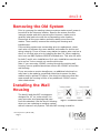
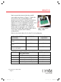
1
dmc3-4 Installation
Instructions
$QEG
1.
dmc3-4
Introduction
Designed to update older intercom systems, the dmc3-4 is a wholehouse music communications system that uses your existing intercom
3 or 4 conductor system wire. It is designed to provide years of
enjoyment and service to the homeowner.
M&S audio products are backed with more than 50 years of experience
in the design and manufacture of precision acoustical equipment for
the home. To ensure that the homeowner receives the high-quality
music and voice reproduction that the system is designed to deliver, it
is important that each step of the installation be done carefully. In the
event you need troubleshooting installation assistance, please call our
technical staff at 1-800-421-1587.
Prior to installing the dmc3-4 system, read and observe the Important
Safety Instructions beginning on page 3.
Our web address is www.mssystems.com. The M&S Systems web site
contains additional information that will be of assistance in the
installation and support of the dmc3-4 system and all other M&S
Systems products. Including installation guides, configuration
recommendations, brochures, product specifications and a frequently
asked questions section.
www.mssystems.com | 800.421.1587 | www.mssystems.com
Page 2
$QEG
1.
dmc3-4
Important Safety
Instructions
READ ALL INSTRUCTIONS CAREFULLY BEFORE
INSTALLING OR USING THE DMC3-4 SYSTEM
THE dmc3-4 MUST BE INSTALLED BY A M&S SYSTEMS DEALER
OR INSTALLER, AND MUST CONFORM TO ALL LOCAL BUILDING
AND ELECTRICAL CODES.
Warning: Always follow these safety instructions.
Retain these instructions for future system reference.
• Read ALL safety and operating instructions before installing the
dmc3-4.
•
Adhere to all warnings on the dmc3-4 and in these instructions.
Follow all operating and installation instructions.
•
CAUTION: These installation instructions are for use by qualified
personnel only. To reduce the risk of electric shock, do not perform
any servicing other than that contained in the operating instructions
unless you are qualified to do so.
•
DO NOT attempt to service the dmc3-4 yourself as opening or
removing covers may expose you to dangerous voltage or other
hazards. Refer all servicing to qualified service personnel.
www.mssystems.com | 800.421.1587 | www.mssystems.com
Page 3
$QEG
1.
dmc3-4
The lightning flash with arrowhead
symbol within an equilateral
triangle is intended to alert the
user to the presence of uninsulated
“dangerous voltage” within the
product’s enclosure that may be of
sufficient magnitude to constitute a
risk of shock to persons.
The exclamation point within an
equilateral triangle is intended to
alert the user to the presence of important operating and maintenance
(servicing) instructions in the literature accompanying the product.
•
Locate the system away from heat sources such as radiators, heat
registers, stoves, or other heat producing products.
•
Do not locate the dmc3-4 master or room stations in an outside
wall.
•
Do not expose the dmc3-4 to moisture. Doing so can create fire or
shock hazards and impair the warranty.
•
Do not place the dmc3-4 master or room stations in any wall cavity
with any other electrical wiring in the cavity.
•
Do not expose the dmc3RW, dmc4RW or dmc1RW outdoor patio
speakers to significant water contact. The patio speakers are
weatherproof but not waterproof. Continuous, direct water exposure
will cause system problems.
•
Do not attach devices unauthorized for use with this system.
Authorized devices include:
•
• Audio components connected via a line level input
• dmc1CD 6-disc player
Use only M&S Systems certified replacement parts and have them
installed by an M&S Systems dealer or installer. Unauthorized
substitutions can result in fire, electric shock, or other hazards.
www.mssystems.com | 800.421.1587 | www.mssystems.com
Page 4
$QEG
1.
dmc3-4
•
Upon completion of any service or product repair, have the M&S
Systems dealer or installer conduct a safety check to ensure the
system is in proper operating condition.
•
Use only a damp cloth to clean the dmc3-4 master and room
stations. Do not use liquid cleaners or aerosol cleaners.
Cautions: Wiring
•
A qualified electrician must run a 120V AC line to the dmc3-4
retrofit transformers.
•
Individual wire runs should not exceed more than 350 FEET of wire
from any single room station to the dmc3-4 master or 1000 total
feet for the entire system.
•
LABEL all wiring runs. Connecting the wires to the dmc3-4 master,
room station or door stations incorrectly may result in system
damage.
•
Run a single cable from the master unit location to each room
station and door station in a “home run” fashion. Do not loop cable
from one room station to another.
•
DO NOT STAPLE CABLES! Staples cause shorts.
•
DO NOT SPLICE CABLES. Splices are unreliable and defeat the
signal isolation properties of the cables.
•
DO NOT RUN ELECTRICAL WIRES THROUGH THE DMC WALL
HOUSINGS. If you encounter 120VAC wires running through a wall
housing during a retrofit you must have a qualified electrician rerun
those wires around the wall housing.
•
KEEP CABLES AT LEAST 18 INCHES FROM FLORESCENT LIGHT
FIXTURES, DIMMER CONTROLS, AND ALL OTHER WIRING. This
includes AC wiring, security cable, cordless phone units, and other
control wires. These can cause a “hum” or “buzzing” sound.
www.mssystems.com | 800.421.1587 | www.mssystems.com
Page 5
$QEG
1.
dmc3-4
•
KEEP cables away from objects such as heating and air conditioning
ducts, metal construction plates, and anything else with sharp
edges that can damage the cables.
Cautions: Room Station Rough-In
Careful consideration should be used when determining the location of
the room stations and master. Since this is a retrofit system you will
not be able to control the location of the existing system. But please
follow the guidelines below if you install any new locations:
•
DO NOT install room stations in return air ducts.
•
DO NOT install room stations in exterior walls. Insulation materials
will change speaker range and efficiency. Temperature changes in
the wall will reduce speaker life.
•
DO NOT install room stations in saunas. They will not withstand the
extreme heat and moisture.
•
DO NOT install room stations underneath cabinets or over counter
tops.
•
DO NOT install room stations in stud cavities with other wiring or
appliances.
•
DO NOT install room stations within 18” of dimmers, fluorescent
light fixtures, security wiring, cordless phone units, and other
control wiring.
•
DO NOT install room stations within 10 feet of other room stations
or the dmc3-4 master unit. This will cause acoustic feedback.
•
DO NOT install room stations in stud cavities with other room
stations or the dmc3-4 master unit. This will cause acoustic
feedback.
•
DO NOT install room stations facing other room stations or the
dmc3-4 master unit. This will cause acoustic feedback.
•
DO make sure all mounting rings are level and oriented as shown in
these instructions.
www.mssystems.com | 800.421.1587 | www.mssystems.com
Page 6
$QEG
1.
dmc3-4
Installation Overview
The dmc3-4 retrofit installation is completed using the following steps:
•
Develop the job estimate
•
Removal of the old intercom system
•
Install the dmc1H or dmc1HC housing
•
Replace the room stations (note do not remove the existing
room station mounting rings)
•
Install the optional dmc1CD player
•
Install the dmc3-4 master and make all room station
connections
•
Test the system
The following tools are required for the dmc3-4 installation. The use of
these or other tools is dependent on the existing intercom system
installation:
•
#2 Phillips screwdriver
•
Wire stripper/cutter
•
Tape measure
•
Level
•
Tin Snips
•
Digital Multimeter (dmm)
•
Small (or precision size) Philips/Flat head screw driver
•
Power drill with 1" auger
•
Small Crowbar
•
Large Flat head screw driver
•
Rubber mallet
•
Extension cord
www.mssystems.com | 800.421.1587 | www.mssystems.com
Page 7
$QEG
1.
dmc3-4
•
Wood chisel
•
Dry wall saw
You may not need to use all these tools on each install but having
them handy will make the overall installation process easier.
Develop the Job Estimate
It is critical that you determine the complexity of each retrofit
installation prior to developing the job estimate. It is hard to predict all
the unique situations you will encounter in the field. For this reason
M&S Systems recommends you visit each retrofit site prior to
developing a job estimate and ordering equipment. During this onsite
visit it is recommended that you complete the items listed below:
•
Determine the model number and manufacturer of the existing
intercom system.
•
Count the number of room, patio, and door stations.
•
Determine if the door and patio stations are surface or flush
mount.
•
Remove the master from the wall to see if any non-standard
installation situations might exist, including:
o Electrical running through the wall housing
o Telephone wires running through the wall housing
o Stud spacing that varies from a standard 16” on center
spacing
o The type of wire used for room, door and patio station runs
(M&S, NuTone or other such as telephone wire) - If you
encounter non-standard wire contact our Technical
Support team at 1-800-421-1587 for assistance.
o A remote transformer
o A remote door chime
The answers to the above information will help you scope, price and
install the retrofit system.
www.mssystems.com | 800.421.1587 | www.mssystems.com
Page 8
$QEG
1.
dmc3-4
Removing the Old System
Prior to removing the existing intercom system make sure all power is
turned off at the intercom location. Remove the screws from the
intercom master and while removing the intercom, make sure to
carefully label each wire with its corresponding room location.
Disconnect all the room station and door station wires from the
master. Then carefully remove the existing wall housing and
transformers.
If the existing system was not working prior to replacement, check
each wire run between the room stations and master for shorts and
wiring integrity. If one of these room station to master wire runs has a
short, re-run that wire prior to installing the dmc3-4. When replacing
wire runs use M&S Systems MS4XSC shielded wire. This wire will work
for both 3 and 4-wire installations. On 4-wire installations use the wire
as is and on 3-wire runs do not use the white wire.
Note: if you encounter 120VAC running through the existing wall
housing, have a qualified electrician reroute the 120VAC around the
wall housing.
If you encounter a remote transformer, an additional electrical run
may have to be made by a qualified electrician to power the dmc
master and/or optional CD player. Also check to make sure that the
area around the housing is clear of any additional 120VAC runs or
other obstructions.
Installing the Wall
Housing
The dmc1H and dmc1HC housings are
designed for 16” on center studs. You
may encounter stud spacings that vary
Figure 1 – Transformer location
from this standard. Use the dmc1H housing
when you are replacing an existing system
with an intercom only system. The dmc1HC housing is used for
www.mssystems.com | 800.421.1587 | www.mssystems.com
Page 9
$QEG
1.
dmc3-4
combination systems only – or those that include the dmc3-4 master
and the optional dmc1CD 6-disc CD player.
Locate wall housing dmc1H or dmc1HC (combo). The housing must be
positioned so that the transformers are on the bottom of the wall
housing as shown in figure 1. If you are replacing the existing master
only system with a combination dmc3-4 system you will have to cut
the rough-in opening larger to
accommodate the larger wall
housing. Prior to making the cutout
check the stud cavity for obstructions
or items in the wall that may prevent
the transformers from fitting in the
wall. The dmc1H and dmc1HC
transformers drop in from the bottom
of the housing. Refer to Figure 2 for
wall housing placement.
The wall housing is designed to fit
between 16" on center (OC) studs. In
retrofit applications you may encounter stud
spacing that varies from this standard.
Figure 2 - dmc1H or dmc1HC wall
housing placement
Connect the existing, dedicated 120VAC/60Hz
line with ground connection from the power
panel to the wall housing as shown in Figure 3.
The dmc3-4 requires a dedicated power source
to assure no interference from other equipment
caused by looped power circuits. The ground is
necessary for proper radio reception.
Figure 3 - Transformer
120VAC/60Hz run
Place transformer enclosure from the inside of the wall housing into
the transformer enclosure opening at the bottom of the wall housing
as shown in Figure 4. Do not run the 120VAC through the wall
housing.
www.mssystems.com | 800.421.1587 | www.mssystems.com
Page 10
$QEG
1.
dmc3-4
For the dmc1HC combo wall housing have a qualified electrician loop a
power wire from the TE5C transformer enclosure to the TE2C
transformer enclosure following the same
procedure described
above and shown in
TE5C
TE2C
Figure 5.
Figure 4 – Transformer
placement
Figure 5 - dmc3-4HC
transformer connection
Replacing the Room
Stations
The DMC room and door speakers use the existing wire and speaker
rough-in mounting frames or boxes. To replace the speaker, first
remove the old speaker. Leave the existing room or door station
mounting rings in place.
After removing the room station verify the
integrity of the wire run. Then install the
mounting plate from the DMCFR (finish-out
frame for room stations). Align the plate on
the wall either vertically or horizontally so that
the screw holes line up with those on the
mounting ring or box. Use a
level to make sure the plate
is level. There are several
screw hole locations on the
mounting plate so it can
attach to many rough-in
designs. Mount the plate to
the wall using the screws
provided (Figure 6).
Figure 6 - DMCFR
installation
www.mssystems.com | 800.421.1587 | www.mssystems.com
Page 11
$QEG
1.
dmc3-4
Next connect the wires to the dmc retrofit
room station as shown in Figure 7. Match the
wire colors to the corresponding screw
locations on the dmc3 or dmc4 room stations.
Please make sure to use only dmc3 room
stations in a 3-wire installation and dmc4 room
stations in a 4-wire installation. All 6-wire
installations use the DMC1 room stations.
Please refer to appendix A for a diagram of
which NuTone and M&S systems map to the 3,
4 or 6-wire (requires dmc1 master)
configurations.
Figure 7 - Room Station
Wiring - 3-Wire
Refer to the charts below for the dmc3-4 wiring diagram;
NuTone Wire (IW3 or
equivalent)
M&S 3-Wire
dmc3-4
equivalent
Silver outside or blue
tracer
White
Black
Center conductor or gray
tracer
Black
Red
Other outside copper
wire or red tracer
Green
Green
M&S Wire
M&S or NuTone 4-conductor
gray jacket wire
dmc3-4 equivalent
White
Silver outside gray wire
White
Black
Next copper outside gray wire
Black
Red
Next copper outside gray wire
Red
Outside copper outside gray wire
Green
Green
www.mssystems.com | 800.421.1587 | www.mssystems.com
Page 12
$QEG
1.
dmc3-4
After connecting the room station to the existing
wiring using the diagrams above. Place the room
station through the DMCFR plastic mounting
plate. Position the plate either vertically or
horizontally depending on the room station
replaced. Place the room station into the roughin ring and align the frame with the room station
as shown in Figure 8. Use the screws provided
with the room station to screw the room station
and frame into place. The holes in the room
station align with the holes in the mounting
plate. The room station keeps the plastic frame
in place on the wall.
Figure 8 - Placing
Note the plastic frames are paintable. Please
Room Station in
prime the plastic first and then apply standard
room paint. The white plastic may require two coats of paint to get full
coverage. It is recommended that you paint the frame prior to
mounting it to the wall.
Important: Please label all cables at both ends. Incorrectly connecting
cables to the master, room stations or door stations could result in
system damage.
Patio Speakers
Do not remove the existing patio speaker rough-in. The DMC retrofit
system is designed to fit into the existing enclosure. It is important to
note that M&S patio speakers are weather resistant not water proof.
M&S speakers should not be located in an area that is in direct line of
water from sprinklers, rain or other devices such as power washers.
Please use the DMCFRW finish-out frame in outdoor and high sun
areas. The DMCFRW plastic is designed to withstand sun and resist
fading. If a patio requires a surface mount application use the
www.mssystems.com | 800.421.1587 | www.mssystems.com
Page 13
$QEG
1.
dmc3-4
DMC1HRWS. This is a surface mount box and cover that will support
the DMC1RW, DMC3RW or DMC4RW patio speakers.
To install a patio speaker follow the instructions presented above for
interior room stations.
Door Stations
Remove the old door station but do not
remove the rough-in box or surface mount
box. When replacing a NuTone door
speaker you must use the DMCFD finish-out
frame. The M&S door station sets in the
DMCFD and the screws attach to the
existing rough-in. Connect the door station
with the corresponding color wires. Screw
the door station or door station with
DMCFD frame into the rough-in box as
shown in Figure 9
Figure 9 - DMCFD and Door
Station Installation
External Music Source
The DMC retrofit system supports the use of external music sources.
You can use an existing connection or run a new wire to support local
source connection. To install a new local source follow the steps
detailed in the following paragraphs.
Choose a location for the AWP that will be easily accessible to the
sources that are to be connected to the system (close to the receiver,
TV or DVD player for example). Note: the external source wire run to
the dmc3-4 must not exceed 50 feet.
At this location, attach a single gang box to a wall stud at a center
height of normal wall outlets. Use a low voltage plaster ring in existing
construction installations.
www.mssystems.com | 800.421.1587 | www.mssystems.com
Page 14
$QEG
1.
dmc3-4
Make sure the single gang box extends past the wall stud and into the
room so it will be flush with the sheetrock when it is applied. Run the
Red and Black shielded audio cables (included in the AWPRX) from the
master unit location to the AWP location. Connect the cables.
Installing the Chime
Module
Install the optional chime module MC3 or
MC8 in the wall housing by pressing the
chime module over the 4 plastic standoffs
attached to the wall housing as shown in
Figure 10. Refer to the instructions shipped
with the chime module.
Figure 10 - Chime module
installation
Installing the dmc1CD player
Connect the audio cables to the audio outlets of
the dmc1CD player refer to Figure 11. After
connecting the audio cables and main cable,
connect the power cord from the TE2C
transformer to the power connector on the
dmc1CD.
Ensuring that nothing is between the CD player
and the back of the wall housing (including
Figure 11 - dmc1CD connections
cables), place the dmc1cd player into the lower
opening of the finish out frames including the
dmc1F or dmcFM frames. Use the screws provided to secure the unit in
place.
www.mssystems.com | 800.421.1587 | www.mssystems.com
Page 15
$QEG
1.
dmc3-4
Installing the dmc3-4
The dmc3-4 ships configured for a 3-wire retrofit system. If you are
replacing a 4-wire system you must change the jumper setup on the
dmc3-4 master. The jumper change must be completed before any
cables are
connected. To
change the
jumpers just pull
them off the
existing connection (Figure
12) and place them in the
4-wire position show in
Figure 13.
Suspend the master unit
from the wall housing by
Figure 12 - Default, 3-Wire
Pin Position
looping the third
hand wire (thick
Figure 13 - 4-Wire Pin
Position
green wire) over the hook at the top of the housing. Be careful not to
damage the wall surface.
If the dmc3-4 system has more than 9
room stations, some room selector
Black
switches will control two room stations.
Patio
Connect each Green wire (except patio
Green) to a single green terminal on
the master. Each numbered Green
terminal corresponds to a remote
Green
Shield
station selector switch. Note: No more
Terminal
Red
Wire
Black
than 3 Green wires can be connected to
White
Terminal
Terminal
Terminal
Terminal
any Green terminal and not to exceed
15 speakers for the 4-wire or 13
Figure 14 - dmc3-4 master wire connections
speakers for the 3-wire system. This
limitation does include remote controls
and volume controls but not door stations. The station location can be
www.mssystems.com | 800.421.1587 | www.mssystems.com
Page 16
$QEG
1.
dmc3-4
marked on the inside of the door access panel on the left side of the
dmc3-4 master.
Connect the green wire(s) from the patio station(s) to the Patio green
terminal. Connect the patio Black wire(s) to the patio Black terminal.
Note: Only two patio stations can be connected to the patio terminals.
Connect the Red wire with the other Red wires to the Red terminal.
Connect the White wire with the other White wires to the White
terminal. Refer to Figure 14 for wire placement.
Connect the red and black wires of the door station cables
(MS4DCX/MS4DCXSC) to the red and black door
speaker terminals on the dmc3-4 master as
shown in Figure 15. When using MS4DCXSC
shielded wire, insulate the bare wires using some
of the jacket material to prevent shorting to the
circuit board. Connect this wire to terminal labeled
shield. Connect all orange wires
Figure 15 - Door
from the door stations to the
Station Connections
common terminal on the MC3 or
MC8. Connect each yellow wire to a note selection
terminal. (Do not connect more than one yellow wire
per note terminal.)
Plug in the modular chime plug to the 4 pin
connector labeled as CHIME on the dmc3-4 master
unit as shown in Figure 16.
Figure 16 – Chime
Plug Connection
Connect the optional dmc1CD player RCA cables and control wire.
Connecting the Antenna
Separate the intercom cables from the antenna leads, if grouped together
the intercom cables can shield the antenna leads resulting in poor radio
reception. Keep the antenna leads away from metal ductwork and
aluminum backed insulation. These can also shield the antenna leads.
The number and style of antenna leads will vary based on the intercom
system being replaced. The dmc3-4 system is designed to use the
existing antenna.
www.mssystems.com | 800.421.1587 | www.mssystems.com
Page 17
$QEG
1.
dmc3-4
Follow the steps below to attach a NuTone 300 Ohm twin lead antenna to
the dmc3-4.
1. If the antenna has a plug on the end, cut the plug off
2. Strip the 2 wire ends
3. Connect the wire ends to terminal S1 and S2 on the antenna board
4. Connect a bare jumper wire (a 22 gauge speaker wire works well)
between the S3 and S4 terminals.
Follow the steps below to attach a separate AM/FM antenna system with
300 Ohm FM twin lead and orange AM antenna wire:
1. Connect the FM twin leads to terminal S1 and S2 on the board
2. Connect the AM antenna (orange wire) to terminal S4
3. Terminal S3 is not used in this configuration
Follow the steps below to connect a single orange wire antenna system:
1. Connect the orange wire to either S1 or S2. Note do not connect
the wire to both S1 and S2 doing this will short out the FM antenna
signal.
2. Connect a bare jumper wire (a 22 gauge speaker wire works well)
between the S3 and S4 terminals.
Wireless Remote Control Connection
To install the optional wireless remote control receiver module MCRC,
attach the MCRC module using the Velcro strips provided to the wall
housing. Place the white antenna lead through the hole provided in the
wall housing into the wall cavity. Failure to do so may result in poor range
of the wireless remote control system. Connect the wire harness from the
MCRC to the connector labeled REMOTE on the master.
After the master is installed you must program the transmitter. Complete
this step after completing the system test. To program the transmitter
simultaneously press and release the AUTO and SOURCE buttons. The
display will show RF and SET on it. Then press and hold any button on the
remote until the RF and SET disappear from the display. To cancel this
function, simultaneously press AUTO and SOURCE.
www.mssystems.com | 800.421.1587 | www.mssystems.com
Page 18
$QEG
1.
dmc3-4
MC960 Power Amp Installation
Run the MS7XSC cable
from the dmc1H or
dmc1HC wall housing to
the remote power
amplifier.
MS 3XS C
DMC 1H
Run the MS3XSC cable from the
Figure 17 - Power amp wiring
remote amplifier to
each volume
MS 3XS C control (use the SVC96 for stereo or the MVC1 for mono).
From each volume control, run the MS2SXSC to each
respective speaker as shown in Figure 17.
MS 7XS C
The remote power amplifier should be located in a closet or
utility closet and should be located within 6 feet of a
standard NEMA 5-15R 120VAC receptacle. Install a 1-gang
and a 2-gang box
Figure 18 - Power
at the location for
amp installation
the remote
amplifier on a
stud. Allocate the 1-gang and 2gang boxes relative to one another
as shown in Figure 18. Run all
MS3XSC cables from the volume
controls to the remote amplifier’s
2-gang box.
MC960PA
Run the MS7XSC cable from the
dmc3-4 to the remote amplifier’s 1-gang Figure 19 - Speaker installation
box. The remote amplifier is designed to
mount over the 1-gang and 2-gang boxes on a single stud. Note: The
speaker cables CANNOT be located in the same gang box used for
120VAC wiring.
Each pair of stereo or mono music speakers is controlled by a single
volume control. The volume controls install in a standard single gang box.
Run a MS3XSC cable from each volume control location to the remote
www.mssystems.com | 800.421.1587 | www.mssystems.com
Page 19
$QEG
1.
dmc3-4
amplifier. From each volume control location, run a MS2SXSC cable to
each satellite speaker (left & right) or mono as shown in Figure 19.
Install the appropriate mounting ring for each respective speaker. Follow
the instructions included with the speaker for specific dimensions on the
mounting ring. Secure the MS2SXSC cable from the speaker’s respective
volume control to avoid drywall damage.
Door Release Options
The door release option is a dry contact closure provided by the dmc3-4
master. This dry contact is rated 24V at 2 Amps. The sample applications
below represent some uses of this option. However, only one application
can be used in any dmc3-4 system at a time.
Door or Gate Release Mechanism
Run a single line of PBVM127X1 from the dmc1H or dmc1HC housing to
the door release mechanism. Connect the red and white wires to the two
wire terminals of the door release mechanism.
Run another single line of PBVM127X1 from the dmc1H or dmc1HC
housing location to a gang box next to a 120VAC receptacle where the
remote power transformer (part #240054) will be plugged in. Label and
secure cables at the housing.
The door release switch contacts are very versatile and can be used with
many AC/DC door or switch contacts. Be sure to use the wire and power
supply or transformer specified by the door or gate release product being
used.
Panic Interface with Security System
Run a line of PBVM127X1 from the dmc1H or dmc1HC housing location to
the security control panel. Setup the security panel to receive a normally
open dry contact for panic operation. (Refer to programming procedures
accompanying the security panel). Label and secure cables at the dmc1H
or dmc1HC housing. Have a certified security installer hook the dmc3-4
up to the alarm system.
www.mssystems.com | 800.421.1587 | www.mssystems.com
Page 20
$QEG
1.
dmc3-4
Test the System
After all connections have been made, insert the dmc3-4 power plug into
TE5C transformer and secure the master to the wall housing using the 2
screws provided. If using the dmc1F, dmc1FC or dmc1FM frame with a
dmc1CD player, install the master unit over the frame. Do not over
tighten the screws as the plastic may distort or crack. Install the speaker
panel on the master as shown in Figure 20.
Please be careful to only apply pressure on the speaker panel at the
corners and not in the middle. Check all functions by following the
guidelines in the Owners Manual shipped with the master unit. If any
difficulties are encountered, recheck all connections. If after reviewing
these instructions you are unable to resolve any problems, contact
technical support at 1-800-421-1587.
Figure 20 - Speaker Panel Placement
www.mssystems.com | 800.421.1587 | www.mssystems.com
Page 21
$QEG
1.
dmc3-4
Appendix A – NuTone Systems
∗
M&S Part Number
DMC1
DMC3-4
DMC1R, DMC1RS
DMC1RW
DMC3R, DMC3RS
DMC3RW
DMC4R, DMC4RS
DMC4RW
DMC1CD
DMC1F
DMCFM
DMCFC
DMCFR
DMCFD
DMC1H
DMC1HC
DMC1HR
DMC1HRW
DMC1HRWS
MC3/MC8
DS3B
BD3BN
D3BN
MCRC
MCTX
DMCRA
NuTone IM3303
NuTone IM4406
X
NuTone IM3204
X
X
X
X
X
X
X
*
X
X
*
X
X
X
X
*
X
X
X
X
*
X
X
X
*
X
X
X
*
X
X
X
X
X
X
X
X
X
X
X
X
X
X
X
X
X
X
X
X
X
X
Refer to frames below:
• DMCFM – Replacing a master
only system with a dmc3-4
master
• DMCFC – Replacing a
combination system with a dmc34 and a dmc1CD
• DMC1F – Replacing a master
only system with a dmc3-4 and a
dmc1CD (requires hole in wall to
be made larger)
• DMCFR – Used on all indoor
room station replacements
• DMCFRW – Used on all outdoor
or high sun area flush mount
room station replacements
• DMC1HRWS – Used on all
outdoor surface mount room
station replacements
• DMCFD – Used on NuTone
door station replacements, not
required for M&S replacements
The following NuTone systems map to either the IM-3303 or IM4406 systems:
NuTone Systems
S M428
2561/2562
2401/2402
2542
2540/2541
IM-406
IM-4006
IMA-303
IMA-203D
IMA-2003
IMA-3003
IMA-3303
2067/2068
2011/2012
2015/2016
2053/2054
2055/2056
2071
2031/2032
2090/2091
M-3103
IM-203
IM-313
IM-4406
X
X
X
X
X
X
X
IM-3303
X
X
X
X
X
X
X
X
X
X
X
X
X
X
X
X
www.mssystems.com | 800.421.1587 | www.mssystems.com
Page 22
$QEG
1.
dmc3-4
Appendix B – M&S Systems
M&S P art Number
DMC 1
DMC 3-4
DMC 1R , DMC 1RS
DMC 1R W
DMC 3R , DMC 3RS
DMC 3R W
DMC 4R , DMC 4RS
DMC 4R W
DMC 1C D
DMC 1F
DMC FM
DMC FC
DMC FR
DMC FD
DMC 1H
DMC 1HC
DMC 1HR
DMC 1HR W
DMC 1HR WS
MC 3/MC 8
DS 3B
BD3BN
D3BN
MC RC
MC TX
DMC R A
M&S P art Number
DMC 1
DMC 3-4
DMC 1R, DMC 1R S
DMC 1RW
DMC 3R, DMC 3R S
DMC 3RW
DMC 4R, DMC 4R S
DMC 4RW
DMC 1C D
DMC 1F
DMC FM
DMC FC
DMC FR
DMC FD
DMC 1H
DMC 1HC
DMC 1HR
DMC 1HR W
DMC 1HR W S
MC 3/MC 8
DS 3B
BD3BN
D3BN
MC R C
MC TX
M&S 602
M&S MC 602 with
MC P /MDC 6
X
X
M&S
MC 702
X
X
X
X
X
X
*
X
X
X
X
X
*
X
X
X
X
X
*
X
X
X
X
X
X
X
X
X
X
X
X
X
X
X
X
M&S 44
S eries
X
M&S MC 702 with
MC P /MC D6
M&S 302
X
X
X
X
X
X
X
*
X
X
X
X
X
X
*
X
X
X
X
X
X
X
X
X
X
X
X
X
X
X
X
X
M&S MC 302 with M&S 440 M&S 500
MC P /MDC 6
Series
S eries
X
X
X
X
X
X
X
X
X
X
X
*
X
X
*
X
M&S 40
S eries
X
X
X
X
*
X
X
X
X
X
X
X
*
X
X
*
X
*
X
*
X
X
X
X
X
X
X
X
X
X
X
X
X
X
X
X
X
X
X
X
X
X
X
X
X
X
X
X
X
X
X
X
X
X
X
X
X
X
M&S
Model 5
M&S
Model 6
M&S
220/330
M&S 250
X
X
X
X
X
X
X
X
X
X
X
X
*
X
X
X
X
*
X
X
X
X
*
X
X
X
X
*
X
X
X
X
*
X
X
X
X
*
X
X
X
X
*
X
M&S
M&S 20
300/350 M&S 350A S eries
M&S 30
M&S
S eries Model 150
X
X
X
X
X
*
X
X
*
X
X
X
X
*
X
X
X
X
X
X
X
X
X
X
X
X
*
X
*
X
*
X
*
X
*
X
*
X
*
X
*
X
*
X
*
X
X
X
X
X
X
X
X
X
X
X
X
X
X
X
X
X
X
X
X
X
X
X
X
X
X
X
X
X
X
X
X
X
X
X
X
X
X
X
X
X
X
X
X
X
X
X
X
X
X
X
X
X
X
X
X
X
X
X
X
X
X
X
X
X
X
X
X
X
X
www.mssystems.com | 800.421.1587 | www.mssystems.com
Page 23
$QEG
1.
dmc3-4
M&S Systems 2-Year Warranty
M&S Systems warrants its products to be free of defects for 2 years. The
warranty period begins on either (a) the date of purchase or installation date of
this product or (b) the date of closing on a new residence in which this product
was originally installed. The warranty extends to the original user of the product
and to each subsequent owner of the product during the term of the warranty.
M&S will repair or replace, at its option, parts and materials at no charge. Parts
supplied under this warranty may be new or rebuilt at the option of M&S
Systems.
If during the warranty period the product appears to have a defect, please call
our toll free service number (800-421-1587) prior to dismantling. Dismantling
the product prior to calling our service number may void the warranty. Before
returning any product to M&S Systems, obtain a Return Authorization Number
(RAN) from our service department. M&S Systems will return the repaired
product freight prepaid within the continental United States. ANY PRODUCT
RETURNED TO M&S SYSTEMS WITHOUT A RAN NUMBER WILL BE REFUSED.
This limited warranty is in lieu of any other warranties, express or implied,
including any implied warranty of merchantability or fitness for a particular
purpose or otherwise, and of any other obligations or liability on the seller’s
part. This limited warranty does not cover damage caused by improper
installation, acts of God, criminal acts, the violation of applicable building or
electrical codes or the use of non-M&S wire, cable (excluding CAT5 and RG-6) or
wall housings.
Under no circumstances shall M&S Systems be liable for consequential,
incidental or special damages arising in connection with use, or inability to use
this product. In no event shall M&S Systems liability hereunder exceed the cost
of the product covered hereby. No person is authorized to assume for us or
obligate us for any other liability in connection with the sale of this product.
Some states do not allow the exclusion or limitation of consequential, incidental
or special damages, so the above limitation or exclusion may not apply to you.
This limited warranty gives you specific legal rights, and you may also have
other rights, which vary from state to state.
116002-2 C
www.mssystems.com | 800.421.1587 | www.mssystems.com
Page 24
$QEG
1.