1
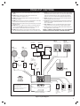
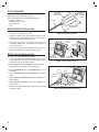
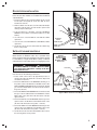
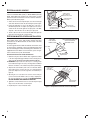
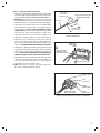
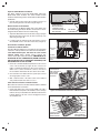
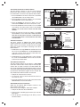
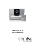
PRINTER’S INSTRUCTIONS:
INSTR,INSTL,DMC1,DMC1MM,FINISH OUT - LINEAR P/N: 230927 AX1 - INK: BLACK - MATERIAL: 20 LB. MEAD BOND - SIZE: 8.500” X 11.000” - SCALE: 1-1 - FOLDING: ALBUM FOLD - BINDING: SADDLE STITCH
INTRODUCTION
Designed for installation in new homes, the dmc1 is a whole-house music and communication system. It is designed to
provide years of enjoyment and service to the homeowner. M&S Systems brand audio products are backed with more
than 50 years of experience in the design and manufacture of precision acoustical equipment for the home. To ensure
that the homeowner receives the high-quality music and voice reproduction that the system is designed to deliver, it is
important that each step of the installation be carefully completed by the installer. In the event you need troubleshooting
assistance, please call our technical support staff at 1-800-421-1587.
dmc1 MUSIC/COMMUNICATIONS SYSTEM
FINISH-OUT INSTRUCTIONS
CAUTION !
The exclamation point within an equilateral triangle is
intended to alert the user to the presence of important
operating and maintenance (servicing) instructions in the
literature accompanying the product.
SHOCK HAZARD !
The lightning flash with arrowhead symbol within an
equilateral triangle is intended to alert the user to the
presence of un-insulated “dangerous voltage” within the
product’s enclosure that may be of sufficient magnitude to
constitute a risk of electric shock to persons.
IMPORTANT SAFETY INSTRUCTIONS
Read Instructions - All the safety and operating
instructions should be read before installing or operating
the dmc1.
Retain Instructions - The safety and operating
instructions should be retained for future reference.
Heed Warnings - All warnings on the appliance and in the
operating instructions should be adhered to.
Follow Instructions - All operating and use instructions
should be followed.
Water and Moisture - The appliance should not be used
near water - for example: near bathtub, washbowl, kitchen
sink, laundry tub, in a wet basement, or near a swimming
pool, and the like. Doing so can create a fire or shock
hazards and impair the warranty.
Cleaning - Use only a dry cloth.
Attachments - Do not use attachments not recommended
by the product manufacturer as they may cause hazards.
Ventilation - The appliance should be situated so that
its location or position does not interfere with its proper
ventilation. For example, the appliance should not be
situated on a bed, sofa, rug, or similar surface that may
block the ventilation openings: or, placed in a built in
installation, such as a bookcase or cabinet that may
impede the flow of air to the ventilation openings.
Heat - The appliance should be situated away from heat
sources such as radiators, heat registers, stoves, or other
appliances (including amplifiers) that produce heat.
Power Sources - The appliance should be connected to
a power supply only of the type described in the rough-in
instructions or as marked on the appliance.
Grounding or Polarization - Precautions should be
taken so that the grounding or polarization means of an
appliance is not defeated.
Power Lines - An outdoor antenna should be located
away from power lines.
Outdoor Antenna Grounding - If an outside antenna
is connected to the receiver, be sure the antenna system
is grounded so as to provide some protection against
voltage surges and built up static charges. Section 810
of the National Electrical Code, ANSI/NFPA No. 70 1984,
provides information with respect to proper grounding of
the mast and supporting structure, grounding of the lead
in wire to an antenna discharge unit, size of grounding
conductors, location of antenna discharge unit, connection
to grounding electrodes, and requirements for the
grounding electrode (see figure).
Object and Liquid Entry - Never push objects of any
kind into this product through openings as they may touch
dangerous voltage points or short out parts that could
result in a fire or electric shock. Never spill liquid of any
kind on the product.
USA & Canada (800) 421-1587 & (800) 392-0123
(760) 438-7000 - Toll Free FAX (800) 468-1340
www.linearcorp.com
Fuses - For continued protection against risk of fire,
replace the fuses in the Master Station or CD Player unit
only with the same type and rating 3 Amp Slo-blo fuses.
Servicing - The user should not attempt to service
the appliance beyond that described in the operating
instructions. All other servicing should be referred to
qualified service personnel.
Damage Requiring Service - The appliance should be
serviced by qualified service personnel when:
■ The power supply cord or the plug has been
damaged; or
■
Objects have fallen, or liquid has been spilled
into the appliance; or
■
The appliance has been exposed to rain; or the
appliance does not appear to operate normally
or exhibits a marked change in performance; or
■
The appliance has been dropped, or the
enclosure damaged.
■
When the product exhibits a distinct change in
performance - this indicates a need for service.
Replacement Parts - When replacement parts are
required, be sure the service technician has used
replacement parts specified by the manufacturer or have
the same characteristics as the original part. Unauthorized
substitutions may result in fire, electric shock, or other
hazards.
Safety Check - Upon completion of any service or repairs
to this product, ask the service technician to perform safety
checks to determine that the product is in proper operating
condition.
Wall or Ceiling Mounting - The product should be
mounted to a wall or ceiling only as recommended by the
manufacturer.
TABLE OF CONTENTS
Tools Required. . . . . . . . . . . . . . . . . . . . . . . . . . . . . . . .
Room Station Installation. . . . . . . . . . . . . . . . . . . . . . . .
Patio Station Installation . . . . . . . . . . . . . . . . . . . . . . . .
Door Station Installation . . . . . . . . . . . . . . . . . . . . . . . .
Satellite Volume Controls. . . . . . . . . . . . . . . . . . . . . . . .
2
2
2
3
3
External Music Source . . . . . . . . . . . . . . . . . . . . . . . . . 4
Intercom Master Station Installation . . . . . . . . . . . . . . . 4
Powering Up the System . . . . . . . . . . . . . . . . . . . . . . . . 9
2-Year Limited Warranty . . . . . . . . . . . . . . . Back Cover
IMPORTANT DO’S & DON’TS
✔ DO ensure that all instructions have been followed before power is applied to
system. The installation shall be carried out in accordance with all applicable
installation rules.
✔ DO use only M&S systems brand cable (except for Cat-5 & RG-6) as called
out in these instructions. The cable is designed and constructed with electrical
specifications necessary for proper audio performance.
✔ DO use only a dry cloth to clean the exterior plastics on the dmc1 Master Station
and Room Stations. DO NOT use liquid or aerosols.
✔ DO make gradual bends of the cable where necessary -- no sharper than 1” radius.
✔ DO dress the cables neatly with cable ties or Velcro™ wraps. Use loose or
moderate pressure.
✔ DO use cable-pulling lubricant only for cable runs that may otherwise require great
force to install. When cable lubricant is used, read the instructions to be sure it is
compatible with the cable jacket material (PVC or FEP).
✔ DO avoid stressing cable conductors, limit pulling tension to 25 pounds or less
as specified by EIA/TIA-568A standard. Pull cables gradually and with constant
tension, taking care not to crush or pinch bundles.
✔ DO use grommets to protect the cable where passing through metal studs or
anything that can possibly damage them.
✔ DO test every installed cable run with a cable tester. “Toning” alone is not acceptable.
✔ DO label every termination point. Use a unique identifier for each cable run. It will
make moves, adds, changes, and troubleshooting easier.
✔ DO support horizontal cable bundles using board supports, J-hooks, or cable trays.
✔ DO have signal cables cross at right angles to power cables to minimize induced
interference.
✔ DO always obey all local and national fire and building codes. Be sure to “firestop”
all cables that penetrate a firewall. Use plenum-rated cable where mandated.
WIRING CAUTIONS
● A licensed electrician must run a 120 VAC line from A DEDICATED 15-AMP
BREAKER to the dmc1 (and dmc1CD or dmc1MM, if equipped) transformer.
● Use Cat-5 wire for all dmc1 wire runs excluding Door Station wire runs. For
Door Stations, use the M&S Systems brand MS4DCXSC wire that is included
with the dmc1H or dmc1HC wall housing kits.
● Individual wire runs should not exceed 350 feet from any single room or Door
Station to the dmc1 Master Station or 1000 feet total for the entire system.
● Label all wire runs. Connecting the wires to the dmc1 Master Station, Room
Station, or Door Station incorrectly may result in system damage.
● Run a single cable from the Master Station unit location to each Room Station
and Door Station in a “home run” fashion. Do not loop cable from one Room
Station to another.
● DO NOT STAPLE CABLES. Staples cause shorts.
● DO NOT SPLICE CABLES. Splices are unreliable and defeat the signal
isolation properties of the cable.
● KEEP CABLES AT LEAST 18 INCHES FROM FLUORESCENT LIGHT
FIXTURES, DIMER CONTROLS, AND ALL OTHER WIRING. This includes
AC wiring, security cable, and other control wires. These can cause a “hum” or
“buzzing” sound.
● Keep cables away from objects such as heating and air conditioning ducts,
metal construction plates, and anything else with sharp edges that can damage
the cables.
✔ DO follow the grounding and bonding requirements established by Electrical Code
TIA standard 607, and equipment manufacturer’s specifications.
✔ DO NOT locate the dmc1 Master Station or Room Stations in an exterior wall.
✔ DO NOT locate the dmc1 Master Station or Room Stations in any wall cavity with
any other electrical wiring in the cavity.
✔ DO NOT locate Patio Stations in places with direct exposure to sun and weather or
in locations that receive direct water spray.
✔ DO NOT attach non line-level audio devices or non M&S authorized equipment to
the system.
✔ DO NOT power up Master Station until all speakers and stations are connected.
✔ DO NOT splice or repair cables damaged during wire pulling, install a new cable.
✔ DO NOT coil or bundle the cables. This can cause electronic feedback.
✔ DO NOT over-tighten the screws for the volume controls, speakers, or the intercom
Master Station to prevent cracking.
✔ DO NOT install any station or speaker cables inside the 120 VAC transformer
enclosure.
✔ DO NOT tie cables to electrical conduits or lay cables on electrical fixtures. Keep
cables at least 16” away from fluorescent lights, HID light fixtures, or dimmers.
✔ DO NOT allow the cable to be sharply bent or kinked at any time.
✔ DO NOT install cables “taught” in the ceiling or elsewhere. A good installation
should have cables loose, but never sagging.
✔ DO NOT run signal cables parallel to power cables without adequate separation to
minimize induced interference.
✔ DO NOT exert more than 25 pounds of tension on 4-pair cables.
✔ DO NOT step on Cat-5 cable during installation.
✔ DO NOT overtighten the cable ties, apply cable ties loosely, with random spacing.
✔ DO NOT untwist the wire pairs in Cat-5 cable more than 1/2” to avoid crosstalk.
ROOM STATION CAUTIONS
Careful consideration should be used when determining the location
of the Room Stations. DO NOT install these devices in the following
locations:
✔ DO NOT install Room Stations near air return ducts.
✔ DO NOT install Room Stations in exterior walls. Insulation materials will change
speaker range and efficiency. Temperature changes in the wall will reduce
speaker life.
✔ DO NOT install Room Stations in saunas. They will not withstand the extreme
heat and moisture.
✔ DO NOT install Room Stations underneath cabinets or over counter tops.
✔ DO NOT install Room Stations in stud cavities with other wiring or appliances.
✔ DO NOT install Room Stations within 10 feet of other Room Stations or the
dmc1 Master Station unit. This will cause acoustical feedback.
✔ DO NOT install Room Stations in stud cavities with other Room Stations or the
dmc1 Master Station unit. This will cause acoustical feedback.
✔ DO NOT install Room Stations facing each other Room Stations or the dmc1
Master Station unit. This will cause acoustical feedback.
Be sure that all Room Station mounting rings are level and oriented
as shown in these instructions.
Failure to adhere to these instructions can cause equipment
malfunction and void any warranty covered by Linear LLC.
FINISH-OUT CAUTIONS
✔ DO NOT install the dmc1 system until after the application of any wall covering
material.
✔ DO NOT install any satellite speakers that are rated other than 45-ohms
impedance. Damage to the amplifier will occur.
✔ DO NOT power up the dmc1 Master Station unit until all remote stations and
speakers are connected.
✔ DO NOT connect Cat-5 wire if you are unsure of its terminating point. Connecting a
door speaker to a Room Station may result in system damage.
✔ DO ensure that all rough-in instructions have been followed before power is applied
to the dmc1 system.
✔ DO NOT attach devices unauthorized for use with this system. Authorized devices
include: (1) dmc1MM CD/MP3 Dock/Player; (2) dmc1CD 6-disc CD Player; (3)
Audio components connected via the line level or docking inputs.
✔ DO NOT install Patio Stations in locations subject to direct sunlight or water spray.
Patio stations MUST be installed in protected areas such as a covered patio or porch.
Door Release
Mechanism
Failure to adhere to these instructions can cause equipment
malfunction and void any warranty covered by Linear LLC.
Remote Power
Transformer
DRW
NR8P
8" Flush Mount
Speaker
✔ DO NOT connect extra cables that may have been run for future speaker additions.
Care must be taken to ensure these cables are not connected to the dmc1 Master
Station unit. Un-terminated cables (no station) connected to the dmc1 Master
Station may cause electronic feedback that will damage the Master Station unit.
✔ DO NOT over-tighten the screws for the remote stations or the Master Station as
the plastic face panels may crack or strip out.
✔ Use only M&S Systems certified replacement parts and have them installed by a
qualified dealer or installer. Unauthorized substitutions can result in fire, electric
shock, or other hazards.
✔ Upon completion of any service or product repair, have the dealer or installer
conduct a safety check to ensure the system is in proper operating condition.
✔ Use only a damp cloth to clean the dmc1 Master Station and Room Stations. Do
not use liquid cleaners or aerosol cleaners.
DMC1R
Standard Room Station
DMC1RS
Standard Room Station
w/Remote Scan
(DMC1HR)
(DMC1HR)
Security Panel
RT11
NR8P
8" Flush Mount
Speaker
Dry Contact
Closure for
Door Release
Either
(NR8-5)
Dry Contact
Closure for
Panic Operation
Supports up to 15 room or patio stations
Antennas
Included with
Wall housings
AM
FM
MS2SX5SC
Modular
Door
Chime
CAT5
CA
T5
CA
T5
CA
T5
MVC1
Volume Control
(1-Gang Box)
DMC1RW
Patio Station
MC3
or
MC8
Door Stations
Available in
White, Bright Brass,
Antique Brass,
or Nickel
DC
S4
M
DMC1
EXAMPLE
SYSTEM
DIAGRAM
M
S4
XS
DC
C
XS
C
DMC1 Music/Communication System (DMC1H Housing Required)
This diagram is for product reference only.
Refer to installation instructions for product
limits and specifications.
Model numbers in parentheses represent
standard rough-in components.
DMC1MM (DMC1F Frame Required)
(DMC1HC Housing Required)
AWP
Audio Input
Wall Plate
for External
Stereo Sources
DS3
Door Speaker
(ME3)
DS3B
Door Speaker
w/Bell Button
(ME3)
(AWP)
Figure 1. System Diagram
1
TOOLS REQUIRED
The finish-out installation should be made after the
application of any wall covering material.
The tools required for the installation finish-out are:
• #2 Phillips screwdriver
• Standard flat head screwdriver
• Wire stripper/cutter
• Level
STRIP EACH
WIRE BACK
MAXIMUM
1/2 INCH
KEEP CABLE
PAIRS TWISTED
TO REDUCE HUM
CAT-5 CABLE
STRIP CABLE JACKET
BACK 4 INCHES
ROOM STATION INSTALLATION
1. Collect all the connectors included in the Room Station packages and
place them in the wall housing for use later.
Figure 2. Cat-5 Wire Preparation
2. At each Room Station location, strip approximately 4 inches of jacket
from the Cat-5 cable and separate the colored wires. Strip 1/2 inch of
insulation from each wire as shown in Figure 2.
3. Connect each colored wire to its respective screw terminal in the
Room Station. Note that some screw terminals have more than one
wire connected to them.
ORANGE / WHITE
ORANGE
GREEN / WHITE
4. Mount each Room Station to its mounting ring using the two screws
provided with each dmc1 Room Station as shown in Figure 3.
CONNECT
CAT-5
WIRES
PATIO STATION INSTALLATION
CAT-5
Use wire nuts for the following connections.
1. At each Patio Station location, strip approximately 4 inches of jacket
from the Cat-5 cable and separate the colored wires. Strip 1/2 inch of
insulation from each wire as shown in Figure 2.
BROWN &
BLUE / WHITE
MOUNTING
RING
ROOM
STATION
GREEN &
BROWN / WHITE
MOUNTING
SCREWS
BLUE
Figure 3. Attaching Room Station
2. Connect ORANGE wire to the ORANGE wire on the Patio Station.
PATIO
STATION
3. Connect BLUE wire to the BLUE wire on the Patio Station.
4. Connect ORANGE/WHITE wire to the ORANGE/WIRE wire on the
Patio Station.
5. Connect GREEN/WHITE wire to the GREEN/WIRE wire on the Patio
Station.
6. Connect GREEN and BROWN/WHITE wires to the GREEN wire on
the Patio Station.
7. Connect BROWN and BLUE/WHITE wires to the BROWN wire on
the Patio Station.
8. Mount the Patio Station to the housing using the two screws provided
with the Patio Station.
2
ORANGE
BLUE
ORANGE
BLUE
ORANGE / WHITE
ORANGE / WHITE
GREEN / WHITE
CAT-5
GREEN &
BROWN / WHITE
BROWN &
BLUE / WHITE
GREEN / WHITE
GREEN
BROWN
Figure 4. Patio Station Wiring Connections
DOOR STATION INSTALLATOIN
Door stations are an intercom speaker that mounts by a
home entrance door. Models are available with and without
a doorbell button.
1. At each Door Station location, strip approximately 4 inches of jacket
from the cables and separate the colored wires. Strip 1/2 inch of
insulation from each wire.
2. At the Door Station end of the cable, cut off the cable’s drain wire (the
shield wire) all the way back to the cable sheath to prevent it from
shorting to any Door Station parts.
BLACK
RED
3. If the Door Station has a bell button, connect the YELLOW and
ORANGE to the bell button’s screw terminals (either wire to either
terminal).
4. Use a wire nut to connect the RED wire to the RED Door Station
speaker wire.
5. Use a wire nut to connect the BLACK wire to the BLACK Door Station
speaker wire.
MS4DCXSC
CABLE
FROM MASTER
ORANGE
6. Tuck the wires into the enclosure and mount the Door Station using
the two screws provided.
Figure 5. Door Station Installation
SATELLITE VOLUME CONTROLS
Monaural 45-ohm speakers can be connected to the dmc1
Master Station to distribute radio, CD, or portable music
player sound throughout the installation. Each mono speaker
is controlled by a single Model MVC1 (white) or MVC1A
(almond) volume control that mounts in a single-gang J-box.
YELLOW
WARNING !!!
USE ONLY A 45-OHM
INTERCOM SPEAKER
OR DAMAGE TO MASTER
MAY OCCUR !!!
45-OHM
INTERCOM
SPEAKER
CAUTION
ANY SPEAKER CONNECTED TO THE DMC1 MUST BE 45 OHMS!
Do not connect any 8 ohm speakers or damage to the dmc1
Master Station will occur!
Use wire nuts for the following connections.
1. At each volume control location, strip approximately 4 inches of
jacket from the cables and separate the colored wires. Strip 1/2 inch
of insulation from each wire.
2. Connect the SHIELD wire from the MS2SX5SC cable that goes to
the speaker location to the RED wire from the MVC1 volume control
and to the BROWN and WHITE/BLUE wires from the Cat-5 cable that
goes to the dmc1 Master Station. (Four wires in this wire nut, this is
the ground connection.)
3. Connect the GREEN and WHITE/BROWN wires from the Cat-5 cable
that goes to the dmc1 Master Station to the GREEN wire from the
MVC1 volume control. (Three wires in this wire nut, this is the audio
signal connection.)
VIOLET
SHIELD WIRE
CAT-5 CABLE
FROM MASTER
VIOLET
BLUE
MS2SX5SC
SPEAKER
CABLE
BLUE
BROWN &
BLUE / WHITE
RED
MVC1
MONAURAL
VOLUME
CONTROL
THESE WIRES ARE
NOT CONNECTED
GREEN &
BROWN / WHITE
GREEN
Figure 6. MVC-1 Volume Control Wiring
4. Connect the BLUE wire from the MS2SX5SC cable that goes to the
speaker location to the BLUE wire from the MVC1 volume control.
(Two wires in this wire nut, this is the speaker – connection.)
5. Connect the VIOLET wire from the MS2SX5SC cable that goes to the
speaker location to the VIOLET wire from the MVC1 volume control.
(Two wires in this wire nut, this is the speaker + connection.)
6. Tuck the wires into the J-box and mount the MVC1 volume control to
the J-box using the two screws provided.
3
EXTERNAL MUSIC SOURCE
AWPMRX
ROUGH-IN
The dmc1 Master Station can play audio from an external
source. The Model AWP (white) or Model AWPA (almond)
Audio Input Wall Plate features two stereo pairs of RCA
jacks that can be connected to a stereo receiver, television,
DVD, or portable music player.
1. At the location for the audio input wall plate, access the left and right
audio cables that were routed to the J-box during the system rough-in.
2. Connect the RCA plugs to each of the RCA jacks on the rear of
the AWP wall plate. Two “Y” adapters (not supplied) can be used to
combine the two left and two right line level input jacks on the AWP
wall plate so the homeowner can use either pair of input jacks.
CONNECT AUDIO
INPUT CABLES TO
BACK OF INPUT PLATE
AWP AUDIO INPUT
WALL PLATE
USE "Y" ADAPTERS
TO CINNECT BOTH
SETS OF INPUT JACKS
ATTACH PLATE
WITH TWO SCREWS
Figure 7. AWP Audio Wall Plate Wiring
3. Tuck the cables into the J-box and mount the AWP audio input wall
plate to the J-box using the two screws provided.
INTERCOM MASTER STATION INSTALLATION
Screw-down Connector Cable Termination
1. Gather all room, patio, and Door Station cables together and cut them
to the same length leaving approximately 12 inches entering into the
wall housing. BE SURE THAT THE CABLES REMAIN LABELED.
✔ IMPORTANT: Verify all cable run locations prior to connecting if they
were not labeled at rough-in. Incorrectly connecting cables to the Master
Station, Room Stations, or Door Stations may result in system damage.
2. Strip back the outer insulation jacket of the room and Patio Station
Cat-5 cables 2 inches to expose the four color coded twisted wire
pairs inside. Strip back each of the eight wires 1/4” maximum (see
Figure 8).
3. Observing the color code label on the connector, insert a wire pair
(solid color wire and wire with the same color stripe) completely into
the connector terminal holes (see Figure 9). TO PREVENT SHORTS,
BE SURE THE WIRES ARE COMPLETELY INSERTED.
4. Tighten the connector terminal screws to secure the wire pair. Repeat
Steps 4 & 5 for the other three colored wire pairs.
5. Repeat Steps 2-4 for each of the Cat-5 cables.
4
KEEP CABLE
PAIRS TWISTED
TO REDUCE HUM
FOR SCREW-DOWN CONNECTORS
STRIP EACH WIRE BACK
MAXIMUM 1/4 INCH
CAT-5 CABLE
STRIP CABLE JACKET
BACK 2 INCHES
Figure 8. Cat-5 Cable Preparation for
Screw-down Connectors
FOLLOW COLOR
CODE LABEL
ON CONNECTOR
OR
OR AN
G
BL A N E
G
BL UE E /
U
W
BR E /
HI
TE
BR OW WH
I
N
T
O
GR W
E
GR EE N /
EE N WH
IT
N
E
/W
HI
TE
The dmc1 Master Station connects to the room, patio, and
Door Station wires at the wall housing location. All other
connections to the Master Station are also made at the wall
housing location.
To ensure good electrical and mechanical connections, and
to avoid service call-backs, refer to the following steps and
the associated figures when terminating wires. Stations are
supplied with screw-down Cat-5 connectors, press-on type
Cat-5 connectors may also be included.
TIGHTEN SCREWS
FOR EACH WIRE
Figure 9. Completed Screw-down Connector Assembly
Press-on Connector Cable Termination
1. Gather all room, patio, and Door Station cables together and cut them
to the same length leaving approximately 12 inches entering into the
wall housing. BE SURE THAT THE CABLES REMAIN LABELED.
✔ IMPORTANT: Verify all cable run locations prior to connecting if they
were not labeled at rough-in. Incorrectly connecting cables to the Master
Station, Room Stations, or Door Stations may result in system damage.
KEEP CABLE
PAIRS TWISTED
TO REDUCE HUM
CAT-5 CABLE
2. Strip back the outer insulation jacket of the room and Patio Station
Cat-5 cables 2 inches to expose the four color coded twisted wire pairs
inside (see Figure 10). DO NOT STRIP THE INDIVIDUAL TWISTED
PAIRS OF WIRE. The connectors have internal sharp edge insulation
displacement wire guides that cut through the insulation on the
copper wires when the connector’s wire latches are snapped closed.
STRIP CABLE JACKET
BACK 2 INCHES
Figure 10. Cat-5 Cable Preparation for
Press-on Connectors
3. Open the four clear plastic wire latches on a connector (see Figure 11).
4. Observing the color code label on the connector, insert a wire pair
(solid color wire and wire with the same color stripe) completely into
the two wire holes in the clear plastic wire latch for that pair color (see
Figure 11). BE SURE THE WIRES ARE COMPLETELY INSERTED.
5. Hold the wires completely inserted while pressing down firmly on the
clear plastic wire latch. The latch will click twice as the wires are being
seated into the internal insulation displacement wire guides. See
Figure 11. VERIFY THAT THE TAB ON THE CONNECTOR BODY IS
INSIDE THE TAB SLOT ON THE CLEAR PLASTIC WIRE LATCH.
6. Repeat Steps 4 & 5 for the other three wire pairs on the cable. Check
each wire’s connection by gently pulling on the wire. With a good
connection, the wire will not pull out of the connector (see Figure 12).
7. Repeat Steps 2-6 for each of the Cat-5 cables.
✔ NOTE: If the connector is re-opened, and any wire is removed from
the connector, cut the cable back and start over.
FOR PRESS-DOWN CONNECTORS
DO NOT STRIP EACH WIRE
2
1
PRESS
DOWN
FIRMLY
INSERT WIRE PAIRS
INTO HOLES THEN
HOLD WIRES IN PLACE
3
LATCH SNAPS INTO TAB
Figure 11. Latching Cat-5 Connector
ORANGE
ORANGE / WHITE
BLUE
BLUE / WHITE
BROWN
BROWN / WHITE
CONNECTOR SHOWN
WITH LEVERS ON TOP
GREEN
GREEN / WHITE
Figure 12. Completed Press-on Connector Assembly
5
Optional Chime Module Installation
The dmc1 supports the 3-note Model MC3 and 8-note
Model MC8 chime modules. The chime module installs
inside the wall housing and is activated by the Door Station
pushbutton.
1. Install the chime module circuit board by snapping it onto the four
plastic mounting standoffs in the wall housing. See Figure 13.
Master Station Pre-installation
To aid wiring of the Master Station unit to the cables from
the wall housing, the Master Station unit contains a wire to
hang the Master Station from the wall housing.
1. Suspend the Master Station unit from the wall housing by looping the
third hand wire (the thick green wire) into the hook at the top of the
wall housing (see Figure 14).
CHIME MODULE
MOUNTS ON FOUR
STANDOFFS INSIDE
THE DMC1H OR DMC1HC
WALL HOUSING
Figure 13. Optional Chime Module Installation
2. If a chime module was installed, plug the chime module’s connector
into the CHIME connector on the dmc1 circuit board (see Figure 15).
Room Station and Music Speaker
Connection to Master Station
The dmc1 Master Station has 15 sockets for the Cat-5 quick
connectors. If the system has more than nine Room Stations,
some Room Station pairs will share the same station
selector switch. Music speaker volume controls also
connect to the quick connector sockets. A MAXIMUM OF 15
SPEAKERS IN ANY COMBINATION (ROOM STATIONS,
PATIO STATIONS, OR 45-OHM MUSIC SPEAKERS) CAN
BE CONNECTED TO THE SYSTEM.
1. Refer to the room number identification printed next to each connector
socket on the circuit board (see Figure 16). The connector room
number 1-9 identification matches the station selector switches 1-9.
Stations 5, 6, 7, 8, and 9 each have two sockets for connection for
two Room Stations that will share the same station selector switch.
2. Insert each Cat-5 Room Station and music speaker quick connector
into the appropriate connector socket.
MC3 OR MC8
CHIME MODULE
DMC1H OR
DMC1HC
WALL HOUSING
"THIRD HAND"
WIRE
DMC1
MASTER
USE GREEN
WIRE TO HANG
MASTER DURING
HOOKUP
Figure 14. “Third Hand” Hanging Wire
PLUG CONNECTOR
FROM CHIME MODULE
INTO THE CHIME
CONNECTOR ON
THE MASTER
3. Write or label the names of the station locations in the numbered
areas provided inside the dmc1 front access door.
Patio Station Connection to Master Station
One connector socket on the dmc1 Master Station is labeled
for the Patio Station connection.
1. Plug the Patio Station quick connector into the PATIO socket. -OR- If
two Patio Stations are required for the installation, use the screw-type
terminal connector provided with the dmc1RW Patio Station and wire
both Patio Stations to the same connector and plug that connector
into the PATIO socket.
Figure 15. Chime Module Connection to Master Station
ROOM 6
ROOM 5
ROOM 4
ROOM 3
ROOM 7
ROOM 8
ROOM 9
ROOM 2
ROOM 1
PLUG EACH STATION
CONNECTOR INTO
CORRECT SOCKET
PATIO
ROOMS 5, 6, 7, 8, & 9
CAN BE SHARED BY
TWO ROOM STATIONS
Figure 16. Station Connections on Master Station
6
Door Station Connection to Master Station
The Door Station connects to the two screw terminals
between the quick connector sockets. If the Door Station
has a bell button, it connects to the optional chime module.
1. Connect the BLACK wire from the Door Station to the screw terminal
labeled DOOR BLACK on the dmc1 Master Station.
2. Connect the RED wire from the Door Station to the screw terminal
labeled DOOR RED on the dmc1 Master Station.
3. Connect the ORANGE wire from the Door Station to the screw
terminal labeled COMMON on the chime module (if chime is used)
4. Connect the YELLOW wire from the Door Station to one of the NOTE
screw terminals on the chime module (if chime is used). DO NOT
CONNECT THE YELLOW WIRE TO MORE THAN ONE NOTE
TERMINAL.
5. Connect the shield wire from the Door Station to the terminal
labeled SHIELDS on the dmc1 Master Station. NOTE: THE SHIELD
WIRE MUST BE INSULATED TO PREVENT IT FROM TOUCHING
ADJACENT COMPONENTS. SLIDE ON SOME INSULATION FROM
A STRIPPED WIRE.
Antenna Connections
The dmc1 contains an AM/FM tuner. Radio reception
requires installation of an AM wire lead antenna, and an FM
dipole antenna. The antennas should have been installed
during the rough-in and require connecting to the dmc1
Master Station.
1. The AM antenna is the single ORANGE wire lead that has the ferrite
filter on it. Connect the ORANGE wire to the AM ANTENNA terminal
on the side of the tuner module in the dmc1 Master Station. The
GROUND terminal remains un-connected.
2. The FM antenna is the coax wire with the Type “F” connector. Connect
the coax wire to the FM ANTENNA connector on the side of the tuner
module in the dmc1 Master Station.
Door Release Connection
The dmc1 Master Station can be wired to a Model DRW
electric door strike. The door release relay has normally open
contacts that are rated at 2 Amps @ 24 Volts AC/DC. The
relay can be activated from the dmc1 Master Station or remote
scan Room Stations (Model dmc1RS) by pressing the volume
up and volume down buttons together for four seconds. The
relay will deactivate when the buttons are released.
1. Identify the two cables labeled “Door Release”.
2. Use a wire nut to connect one wire from the transformer cable to one
wire from the door strike.
3. Connect the remaining wires from each cable to the terminals marked
DOOR RELEASE on the dmc1 Master Station.
External Music Source Connection
Audio from the optional AWP wall plate connects to the
dmc1 auxiliary audio inputs.
Follow these steps if using the audio input wall plate
1. Identify the two RCA cables labeled “AUX INPUT”.
2. Insert the left audio cable RCA plug into the AUX L jack on the dmc1
Master Station.
3. Insert the right audio cable RCA plug into the AUX R jack on the
dmc1 Master Station.
YELLOW ORANGE COMMON
WIRE
WIRE
TERMINAL
MS4DCXSC
CABLE TO
DOOR STATION
NOTE
TERMINAL
(CONNECT TO
ONLY ONE)
SHIELD
WIRE
BLACK
WIRE
RED
WIRE
DOOR BLACK
DOOR RED
SHIELD
NOTE: SLIDE
INSULATION
ON SHIELD
WIRE TO
PREVENT
SHORTS
Figure 17. Door Station Master Station and Chime
Connections
FM ANTENNA
COAX CABLE
AM ANTENNA
WIRE
AM ANTENNA
FERRITE FILTER
(HANGS INSIDE
WALL HOUSING)
FM ANTENNA
AM ANTENNA
AM ANTENNA
CONNECTS TO
THIS TERMINAL ONLY
Figure 18. AM and FM Antenna Connections
FROM RT11
TRANSFORMER
PBVM127X1 CABLE
TO ELECTRIC
DOOR STRIKE
DOOR RELEASE
TERMINALS
Figure 19. Door Release Wiring
PLUG EXTERNAL AUDIO
CABLES INTO LEFT & RIGHT
AUDIO INPUT JACKS
RIGHT
AUXILIARY
INPUT
LEFT
AUXILIARY
INPUT
Figure 20. Auxiliary Input Jacks on Master Station
7
Mounting in a Master Station Only Installation
When the dmc1 Master Station is used without the optional
CD Player, the dmc1 mounts inside the dmc1H wall housing.
Follow these steps for mounting the Master Station.
1. Verify that the circuit breaker controlling the power to the wall
housing transformer is OFF.
BE SURE THE AREA
IN THE WALL HOUSING
BEHIND THE MASTER
IS CLEAR OF CABLES
2. Plug the connector on the dmc1 Master Station’s wiring harness into
the connector on the TE5D power transformer.
3. Secure the dmc1 Master Station to the wall housing using the two
long screws provided (see Figure 21).
4. Install the speaker grille onto the right side of the dmc1 Master
Station. BE CAREFUL NOT TO PRESS IN THE CENTER OF THE
GRILLE! Only press around the edges.
Mounting the Master Station with the Optional
DMC1 iPlay® Dock and CD Player
When the optional CD Player is included, the dmc1 Master
Station and the dmc1CD 6-disc CD Player or dmc1MM
iPlay® Dock - MP3 & CD Player mounts inside the dmc1HC
combination wall housing.
Follow these steps for mounting the Master Station and CD
Player:
1. Verify that the circuit breaker controlling the power to the wall
housing transformers is OFF.
2. Insert one end of the CD Player interface cable into the CD interface
connector on the dmc1 Master Station. This connector is located
in the center of the dmc1 Master Station’s middle circuit board
approximately behind the two TUNE buttons (see Figure 22).
ATTACH THE MASTER
TO THE WALL HOUSING
WITH TWO SCREWS
Figure 21. Master Station Only in dmc1H Wall Housing
PLUG CD INTERFACE
CABLE INTO MASTER
THE CONNECTOR LOCATION IS:
BOTTOM OF MASTER,
MIDDLE CIRCUIT BOARD,
BEHIND THE TUNE BUTTONS
Figure 22. CD Player Interface Connection on Master Station
3. Insert the CD audio cable’s BLACK RCA plug into the CD L jack on
the dmc1 Master Station, then insert the cable’s RED RCA plug into
the CD R jack on the dmc1 Master Station (see Figure 23).
PLUG CD AUDIO CABLES
INTO LEFT & RIGHT
CD AUDIO INPUT JACKS
4. Plug the connector on the dmc1 Master Station’s wiring harness into
the connector on the TE5D power transformer.
RIGHT
CD AUDIO
INPUT
5. Position the dmc1F combination mounting frame over the dmc1HC
wall housing with the larger opening toward the top.
6. Be sure to route the CD interface and audio cables in through the top
opening of the dmc1F frame then down and out the lower opening in
the dmc1F frame.
7. Secure the dmc1 Master Station to the wall housing using the two
long screws provided (see Figure 24). DO NOT OVERTIGHTEN THE
SCREWS THE FRAME MIGHT DISTORT OR CRACK!
8. Install the speaker grille onto the right side of the dmc1 Master
Station. BE CAREFUL NOT TO PRESS IN THE CENTER OF THE
GRILLE! Only press around the edges.
LEFT
CD AUDIO
INPUT
Figure 23. CD Input Jacks on Master Station
DMC1 MASTER MOUNTED
INTO DMC1HC WALL HOUSING
DMC1F COMBINATION
MOUNTING FRAME
CD PLAYER
INTERFACE CABLE
CD PLAYER
AUDIO CABLES
CD PLAYER
POWER CABLE
DMC1HC
WALL
HOUSING
Figure 24. dmc1F Frame with Master Station, Ready for CD
Player
8
Mounting the Master Station with the Optional CD
Player (continued)
9. Insert the CD Player interface cable into the INTERFACE connector
on the CD Player (see Figure 25 or 27).
PLUG INTERFACE
CABLE INTO THE
INTERFACE
CONNECTOR ON
CD PLAYER
10. Insert the CD audio cable’s BLACK RCA plug into the AUDIO LEFT
jack on the CD Player, then insert the cable’s RED RCA plug into the
AUDIO RIGHT jack on the CD Player (see Figure 25 or 27).
AUDIO
RIGHT
11. Plug the connector from the TE2D power transformer in the wall
housing to the CD Player’s POWER connector (see Figure 26 or 27).
12. Be sure that the area where the CD Player will slide into the wall
housing is free of cables and connectors that might be in the way
when the player is inserted.
13. Attach the CD Player to the wall housing using the two long screws
provided as shown in Figure 28. DO NOT OVERTIGHTEN THE
SCREWS THE FRAME MIGHT DISTORT OR CRACK!
DMC1MM
SHOWN
AUDIO
LEFT
PLUG LEFT AND RIGHT
AUDIO CABLES INTO
CD PLAYER AUDIO
JACKS
Figure 25. dmc1MM iPlay® Dock MP3 & CD Player
Interface and Audio Cable Connection
DMC1MM
SHOWN
14. If installing the dmc1CD 6-disc player, connect the EJECT button
cable to the very small two-pin connector located under the lower
right edge of the CD mechanism frame.
15. Install the CD Player faceplate by pressing it onto the player.
PLUG POWER CONNECTOR
FROM THE TRANSFORMER
INTO CD PLAYER'S POWER
CONNECTOR
POWERING UP THE SYSTEM
After all connections have been made and the unit(s) are
installed into the wall housing, follow these steps to power
up the dmc1 system.
1. Turn the circuit breaker controlling the power to the wall housing
transformer(s) ON.
2. Check all functions of the system. Refer to the Owner’s Manual
supplied with the dmc1 Master Station for operation details. If any
difficulties are encountered, recheck all connections.
Figure 26. dmc1MM iPlay® Dock MP3 & CD Player
Power Connection
DMC1CD
SHOWN
AUDIO
LEFT
AUDIO
RIGHT
CD PLAYER
POWER CABLE
CD PLAYER
INTERFACE CABLE
CD PLAYER
AUDIO CABLES
Figure 27. dmc1CD 6-Disc CD Player Connections
MASTER MOUNTED IN
TOP OF WALL HOUSING
CD PLAYER SLIDES
INTO BOTTOM OF WALL
HOUSING
SECURE CD PLAYER WITH
TWO LONG SCREWS, THEN
SNAP ON THE COVER
BE SURE THAT THE AREA BEHIND
CD PLAYER IS CLEAR OF CABLES
Figure 28. CD Player into Wall Housing
9
2-YEAR LIMITED WARRANTY
Linear LLC warrants its M&S Systems brand products to be free of
defects for 2 years. The warranty period begins on either (a) the date of
purchase or installation date of this product, or (b) the date of closing on
a new residence in which this product was originally installed.
The warranty extends to the original user of the product and to each
subsequent owner of the product during the term of the warranty. Linear
will repair or replace, at its option, parts and materials at no charge.
Parts supplied under this warranty may be new or rebuilt at the option
of Linear.
If, during the warranty period, the product appears to have a defect,
please call our toll free number (800-421-1587) prior to dismantling.
Dismantling the product prior to calling our service number may void the
warranty. Before returning any product to Linear, obtain a Return Product
Authorization (RPA) number from our service department. Linear will
return the repaired product freight prepaid within the continental United
States. ANY PRODUCT RETURNED TO LINEAR WITHOUT AN RPA
NUMBER WILL BE REFUSED.
This limited warranty is in lieu of any other warranties, express or
implied, including any implied warranty of merchantability or fitness
for a particular purpose or otherwise, and of any other obligations or
liability on the seller’s part. This limited warranty does not cover damage
caused by improper installation, acts of God, criminal acts, the violation
of applicable building or electrical codes or the use of non-M&S wire or
cable (excluding CAT-5 and RG-6).
Under no circumstances shall Linear be liable for consequential,
incidental or special damages arising in connection with use, or inability
to use this product. In no event shall Linear’s liability hereunder exceed
the cost of the product covered hereby. No person is authorized to
assume for us or obligate us for any other liability in connection with
the sale of this product. Some states do not allow the exclusion or
limitation of consequential, incidental or special damages, so the above
limitation or exclusion may not apply to you. This limited warranty gives
you specific legal rights, and you may also have other rights, which vary
from state to state.
USA & Canada (800) 421-1587 & (800) 392-0123
(760) 438-7000 - Toll Free FAX (800) 468-1340
www.linearcorp.com
Copyright © 2012 Linear LLC
230927 AX1