1
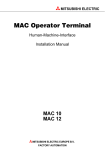
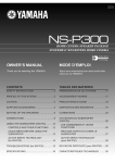
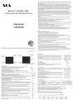
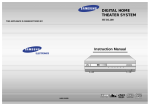
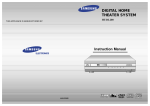
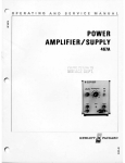
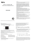
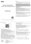
MITSUBISHI ELECTRIC MAC Operator Terminal Human-Machine-Interface User's Manual MAC 10 MAC 12 MITSUBISHI ELECTRIC EUROPE B.V. FACTORY AUTOMATION Manual MAC 10, MTA 10, MAC 12, MTA 12 Foreword This manual presents installation, handling and technical details of MAC 10/MTA 10 version 2.1X and MAC 12/MTA 12 version 1.0X. The terminals are used for MELSEC FX, FX0 and FX0N PLC system. Besides this manual, the following manuals are also available. – FX-series, Programming manual – MAC Programmer, Manual – MAC Programmer+, Manual © Mitsubishi Electric Europe B.V. All examples in this manual are used solely to promote understanding of how the equipment works and its operation. Mitsubishi Electric Europe B.V. takes no responsability if these examples are used in real applications. Because of the great many application areas for this equipment, the user himself must acquire the appropriate knlowledge needed to use the equipment correctly for particular applications. Mitsubishi Electric Europe B.V. absolves itself of all responsabilities for damage and injuries that may occur during installation or use of this equipment. Mitsubishi Electric Europe B.V. absolves itself of all responsabilities for any type of modification made to the equipment. Contents Contents 1 Introduction ............................................................................................ 1 2 Installation .............................................................................................. 3 2.1 Contents of package......................................................................... 3 2.2 System requirements ....................................................................... 3 2.3 Mounting ........................................................................................... 3 2.4 Connection to FX0/FX0N ............................................................... 4 2.5 Connection to FX .............................................................................. 4 2.6 Connection to a Personal Computer ............................................. 5 3 Function overview ................................................................................. 7 3.1 Basic definitions................................................................................ 7 4 How to program the terminal .............................................................. 9 4.1 Communication mode ..................................................................... 9 4.2 Keyboard ........................................................................................... 9 4.3 Creating a project ........................................................................... 10 4.4 Text and system blocks.................................................................. 11 4.5 Static and dynamic information................................................... 12 4.6 Example: Temperature control..................................................... 13 4.7 Transferring a project .................................................................... 19 4.8 Run mode ........................................................................................ 19 5 Databuffer ............................................................................................. 21 5.1 Configuration in the terminal....................................................... 21 5.2 Data control block in the PLC system ......................................... 22 6 "Joystick" function ............................................................................... 23 6.1 Example ........................................................................................... 24 I Contents 7 Programming example ........................................................................ 25 7.1 Structuring textblocks according to application ........................ 25 7.2 Changing text block on display .................................................... 25 7.3 Setting date and time ..................................................................... 29 7.4 Control by time ............................................................................... 30 7.5 Operating machine status.............................................................. 30 7.6 Selection list ..................................................................................... 31 7.7 Dynamic text blocks ....................................................................... 32 7.8 How much can be stored for a project......................................... 32 8 Reference guide .................................................................................... 33 8.1 Project memory size ....................................................................... 33 8.2 Mode selection ................................................................................ 33 8.3 Set-up of the terminal using the PC software............................. 34 8.4 Programming .................................................................................. 38 8.4.1 Creating a project .................................................................... 38 8.4.2 Definition of textblocks .......................................................... 38 8.4.3 Dynamic objects ...................................................................... 40 8.4.4 Definition of time channals ................................................... 48 8.5 Transferring an application........................................................... 49 8.6 Run mode......................................................................................... 49 8.7 Preprogrammed project................................................................. 50 8.8 PLC program transfer .................................................................... 53 II Contents 9 Appendix ............................................................................................... 55 9.1 Modes............................................................................................... 55 9.2 Dynamic object ............................................................................... 55 9.3 System blocks.................................................................................. 55 9.4 Keys .................................................................................................. 56 9.5 Default set-up ................................................................................. 56 9.6 Data .................................................................................................. 57 9.7 Character tables .............................................................................. 58 10 Appendix for drawings (at the back of the manual) .................. A-1 III Contents IV Introduction 1 Introduction This manual describes the operator terminals MAC 10/MTA-10 and MAC 12/MTA-12. Herafter these products are referred to as the terminal. In the manual we refer to the software package MAC Programmer+/ SW-MTA-WIN for Windows and MAC Programmer/SW-MTA for DOS. Hereafter these products are referred to as the PC software. The operator terminal is developed for use with the MELSEC FX0 and FX PLC system to simplify man-machine communication. The functions incorporated in the terminal include those for displaying text with dynamic values, for maneuvring objects and for time channel control. Programming of the terminal is achieved by means of a personal computer and the PC software. In MAC 10/MTA-10 you can use the preprogrammed application supplied as a part of the product. In addition to the sections describing the functions found in the terminal and installation of the terminal, there is a section on how to use the preprogrammed application and another on how to use the PC software to program the terminal. Several useful programming examples and a reference guide are found in this manual. When combined, the terminal and an FX0 PLC form an integrated system for completely replacing hard-wired timers, counters and relays used in very small automation applications such as individual machine control. 1 Introduction 2 Installation 2 Installation 2.1 Contents of package The terminal package includes: – Terminal – Installation manual 2.2 System requirements The terminal works with Mitsubishis programmable logic controllers series MELSEC FX0/FX0N and FX. 2.3 Mounting The terminal can be mounted on a panel or on a DIN rail. To comply with IP65 environmental standard, the terminal should be mounted in a front panel. 32,5 37,5 LCD 72 0 I - + 96 max 36 max 41 max 44 max 49 The different ways of mounting the terminal 3 Installation 2.4 Connection to FX0/FX0N The terminal is supplied with an 8-pin Mini-DIN cable for connection to a FX0 PLC system. The cable is straight; the contact at each end is compatible with both the terminal and the FX0 system. The terminal connector is located in the bottom of the unit, and the FX0 connector is located under a protective cap in the top of the unit. The cable has a maximum length of 3 m and communication speed is 9600 baud. The terminal is powered by the FX0 system via the cable supplied. If a longer cable is required, the terminal must be powered from a source other than the FX0 PLC. 0 - I + Connection of the terminal to FX0 system 2.5 Connection to FX Cable FX-20P-CABN must be used to connect the terminal to a FX PLC system. For other conditions see connection to FX0. 0 - Connection of the terminal to FX PLC system 4 I + Installation 2.6 Connection to a Personal Computer Connection can be made using a SC06N adapter. The maximum cable length is 3 m and the communication speed is 9600 baud. MAC Programmer 0 I - + SC06N Connection of the terminal to a personal computer The terminal is programmed using a personal computer with the PC software. You also use the PC software to make a backup of the terminal project. Later it is also possible to transfer the project to other types of terminls, for example a MAC 50/MTA-250. 5 Installation 6 Function overview 3 Function overview X, Y, M ... D, T, C ... M D MAC 10/MTA-10 MAC 12/MTA-12 3.1 Basic definitions Textblock Textblock are used to create and structure an application. Textblocks can consist of an unlimited number of lines of up to 16 characters long. Static text Static text is text which is written in textblocks and which cannot be changed during RUN-mode. 7 Function overview Dynamic objects Dynamic objects are those objects which are linked to signals in the PLC system. There are 7 types of dynamic objects: digital, analog, jump, date/ time, bar graph, multiple choice and text object. Time channels Time channels make it possible to set a digital signal ON or OFF controlled by the real time clock, that is, to enable you to ensure that a certain function is ON during certain periods of the day. Data logging/menu A part of the project memory in the terminal is set aside for logging data or storing menus. 8 How to program the terminal 4 How to program the terminal This section describes how you can program the terminal with the PC software for Windows (programming can also be done with MAC Programmer for DOS). Refer to the PC software manual for further information. An example will be used later in this section to clarify how the terminal is programmed. 4.1 Communication mode The terminal must be in mode "Communication with PC software" before a program can be transferred from the PC software to the terminal. To set the terminal into this mode press the [←] [-] keys down continuously during power-up of the terminal. 4.2 Keyboard The terminal keyboard incorporates 6 membrane keys which are used to perform the following functions: – Set manoeuvrable digital object (ON). Increase value of manoeuvrable analog object. Execute jump. Select/execute choice from a multiple choice object. + Reset manoeuvrable digital object (OFF). Decrease value of manoeuvrable analog object. Move up one line. If the first line of time channel settings: return to previous level. Move to next field (position). Move to previous field (position). Move down one line. 9 How to program the terminal 4.3 Creating a project Create a new project in the PC software by selecting New from the File menu. Make entries for the project according to the figure below. See the PC software manual for further information. 10 How to program the terminal 4.4 Text and system blocks The main functional tool in the terminal is textblocks. These are used for building up applications. Textblocks are used to build up individual menus, between which you can define jumps. Textblocks can also present the status and value of different signals. A textblock can contain an unlimited number of lines, each of up to 16 characters in length. Textblocks are defined using the PC software on a personal computer. Each block has its own identity number. The first block, the one that is displayed on power up, is always number 0. This block is also called the "Main menu". The following blocks are numbered from 1 to 999. The block numbers 990-999 are reserved for system blocks. Block number 991 is used in the terminal for the time channels. Select New in the block list. Now the block header is displayed. The following parameters can be assigned to textblocks: Block no: Type in a block number or press [F9] to select from a menu. The first text block of a project must be assigned the number 0. Block name: Type in any name of your choice for the textblock. The name can be up to 15 characters long. The name is optional. 11 How to program the terminal Block width: Line length is 16 characters, this cannot be altered. Display signal: You can assign a signal which is used by the PLC-program to display the textblock. The textblock is displayed when the signal is activated. Status This is where you can define the status word for the textblock. Press the button Status.. to display a list of those functions which influence the status words displayed. Functions can be assigned by selecting either YES or NO. The status words displayed will depend on the combination of YES and NO you select. See Reference Guide for information on the functions that effects the status word. When you have completed parameter setting, press [OK] to edit textblocks. See the PC software user manual for more information. 4.5 Static and dynamic information You can manipulate two types of information in textblocks, static text and dynamic data object. Static text does not change during the execution of a program. There are 7 types of dynamic object: digital, analog, jump, date/ time, bar graph, multiple choice and text. The character # defines a dynamic field. The diagram below shows how a channel number can be linked to a dynamic object in a project. Definition INPUT1 X1 ( ) Statisc text #-- Digital obj:X1 Text 0 :OFF Text 1 :ON Manoeuvr. :NO Digital dynamic object The timers and counters in FX0, FX0N and FX have four different values; input condition, output status (digital), preset value and actual value. When the PLC program is written it is clear which value that is referred, due to the position in the relay ladder diagram. 12 How to program the terminal When the terminal should access the preset or actual value it must defined with PRE or ACT. When a timer or counter is used in a digital object, it will always display the status of the output. Preset T1in Condition (Analog) ( T1 ) K Villkor T1 ( ) Preset T1 PRE (Digital) T1 ACT T1out (Digital) T1out (Analog) PLC program Current value Terminal 4.6 Example: Temperature control This example shows how to create an application for energy conservation. The temperature setpoint will be alternated due to the time of day. A time channels is used to set the interval for day temperature. You will also see how you can read the energy consumption in kWh. Block 0 ENERGY:#--- KwH #Set temp.time #Set clock Block 1 Block 991 TIME:#------- Schematic diagram of a project 13 How to program the terminal Menus Select New in the block list. Set the parameters for a textblock according to the picture below. Press [OK] to edit a textblock. Type in the following text on the first line TEMP: 14 How to program the terminal Select Digital text (0/1) in the toolbox.. A dialog box is now displayed to allow you to define the object. Fill in the dialog box according to the picture below. Finish by pressing [OK]. Type the text LEVEL and finish with [Enter]. The first line is now complete and the cursor moves to the next line. 15 How to program the terminal Line 2 Type in ENERGY on the second line. Select Analog object (0,3) in the toolbox. Fill in the dialog box according to the picture below and finish with [OK]. Type in the text kWh and finish the line with [Enter]. Line 3 Select Jump object in the toolbox. Fill in the dialog box according to the picture below and finish with [OK]. Type in the text Set temp.time. End the line with [Enter]. 16 How to program the terminal Line 4 Select Jump object in the toolbox. Fill in the dialog box according to the picture below and finish with [OK]. Type in the text Set clock. End the line with [Enter]. Time channels Time channels in the terminal make it possible for you to instruct that a certain signal should be ON during certain times of the day. Each time channel can have four time intervals. Select Time channels in the View menu. The following will be presented. 17 How to program the terminal Define the time channel according to the following figure. In the dialog you enter the signals that must be set to 1 and define the time intervals when the day temperature is in operation. End definition by pressing [Append]. Return to the block list by pressing [Exit]. Textblock for Date/Time Select New in the block list. Enter the block number 1 and press [OK]. Type DATE:. Select the object Date/time in the toolbox. Carry out parameter setting for the objects according to the following figure. End with [OK]. 18 How to program the terminal Press [Enter] to change line. Type in TIME: on the second line. Select the object Date/time in the toolbox. Carry out parameter setting for the objects according to the following figure. End with [OK]. Note! Date/time is set in run mode using this type of textblock. See example Operating machine status. 4.7 Transferring a project Projects can be transferred between a terminal and a personal computer when the terminal is in communication mode. This mode is selected by pressing the [←] [-] keys down continuously during terminal power-up. For more information see section Transferring an application in the chapter Reference guide. 4.8 Run mode Run mode is selected automatically on power-up. In run mode you can display function status and control a process according to the application in the terminal. For more information see section Run mode in the chapter Reference guide. 19 How to program the terminal 20 Databuffer 5 Databuffer MAC 12/MTA-12 This function means that an area of the battery memory is used as an extra memory bank for the PLC system. The PLC program determines what is to be read/written as well as when/where it is to be done. The size of the memory bank is configured in the terminal. The available buffer area depends on how much project memory is used (maximum project memory is 8000 bytes). The PLC program communicates with the memory bank in the terminal via a data control block (4 registers) in the PLC system. The position in the memory area to read from or write to is stated with an index. Index Memory bank 0 Value 1 1 Value 2 -m Value m+a 5.1 Configuration in the terminal The address in the terminal is configured to the first data control register in the PLC system (see the next section) as is the size of the memory bank (in number of registers, 2 bytes per register). The parameters are defined in the PC software. Select Databuffer Setting in the Setup menu and make the settings according to the following figure. 21 Databuffer 5.2 Data control block in the PLC system The data control block consists of 4 registers: Register Description Dn0 Command register. Dn1 Start index in the memory bank to read from/write to. Dn2 Number of registers to read/write. Dn3 Start register in the PLC system to read from/write to. (e.g. if 100 is stated in this register, reading/writing will begin in register D100). The command register is set in the PLC system and can assume the following values: 1 2 3 Write to memory bank Read from memory bank Fill the selected area with the value found in Dn3 The terminal replies in the same register in a similar way to the following: 0 FFFF 22 Reading/writing completed Error when reading/writing "Joystick" function 6 "Joystick" function MAC 12/MTA-12 With this function it is possible to use the arrow keys as function keys. On the command line under System signals you enter the command AK and an address. For example you can enter AKM100 (the command AK and memory cell M100). Then M100 is the enable signal and the following 4 memory cells are as according to the following control block. Memory cell Description Mn0 Enable. Arrow key detection. Disable=normal function. Mn1 Left key Mn2 Down key Mn3 Up key Mn4 Right key If you press an arrow key when the enable signal is set the memory cell corresponding to the key pressed will be set. When the enable signal is set the normal functions of the arrow keys are disabled. 23 "Joystick" function 6.1 Example The following exampel can be used to exit the joystick function and return to normal function. Make the following steps. – create a block with 1:st man obj defined. – enter the static text "JOYSTICK". – create a digital object with the following settings: D.Signal: Text 0 : Text 1 : Manoeuvr: M100 OFF ON YES The block will look like this: JOYSTICK #-- 24 Programming example 7 Programming example When planning an application there are a number of things to take into consideration. For instance, which blocks should you use and how do you change blocks? We will now try to answer some questions that may arise. 7.1 Structuring textblocks according to application Signals linked to the same object are normally shown together. Suppose we have an application involving 3 motors. The following menu tree can then be made for the blocks: 0 Choice of menu 1 2 3 Motor 1 Motor 2 Motor 3 Menu 1, 2, 3 For instance, block 2 would look like: MOTOR 2 IS ON RUN TIME:20 MIN 7.2 -digital value -timer value Changing text block on display The possibilities that exist for moving between different blocks in Run mode are defined by the application in the terminal, perhaps in conjunction with the PLC program. Note that there may be several ways of moving to a particular block. Jumping between blocks Make a jump object in the displayed block and use it to jump to another block. This function is completely independent of the PLC program. 25 Programming example Block changing controlled by the PLC program When selecting a textblock, define the digital signal that, when activated, displays the text block. In this example we define that text block 5 is displayed when signal X0 is activated. Returning to the previous block used We are in block 20 and want to jump back to the previous block (10, 11 or 12) we were using. Block 10 Disp. sign. M200 Block 11 Block 12 Disp. sign. M201 Disp. sign. M202 Block 20 RETURN 26 Programming example M200-M202 are the display signals for blocks 10-12. In block 20 we make a digital object: To move to block 20 we make jump objects in blocks 10-12. The PLC program looks like this: D0 = current block D1 = the block displayed before block 20 M0 RST M300 Check if D0=20 M8000 CMP D0 K20 M10 M11 PLS M0 Transfer D0 to D1 M11 MOV D0 D1 27 Programming example When M300 is activated we compare D1 with K10-K12 to know which block to jump back to. CMP M21 D1 M300 K10 M20 M200 ( ) M300 CMP M31 D1 M300 K11 M30 M201 ( ) M300 CMP M41 D1 K12 M40 M300 M202 ( END 28 ) Programming example 7.3 Setting date and time To set the right date and time in Run mode, you have to create a manoeuvrable date/time object in a block. If you only want to change the date or time you must create 2 object to avoid problems with the cursor in Runtime mode - one with date only and one with time only. If you want to show a weekday as well, you have to create a third block with the day of the week only. You can never change a weekday, this is automatically calculated from the date entered. It is possible to have manoeuvrable date/time objects in several blocks. Of course, a change in one block will then affect those in other blocks. Note that setting the format for date and time is carried out in configuration mode. Note! The real-time clock can handle the years from 1970 to 2035. If you type in 00 this means the year 2000. If you want to enter the year 1993, press the [-] until 93 is displayed. If you want to enter the year 2010, press the [+] until 10 is displayed. 29 Programming example 7.4 Control by time Use a time channel to control a signal. Note! If the digital signal linked to the time channel exists in the program as an OUT instruction, the PLC program takes command. If this condition is not valid then the signal remains inactive. Changing time channel intervals on-line To make it possible to change time channel intervals during Run mode, you must select YES for time channels under Online changes in Set-up mode. To change intervals on-line, jump to block 991 (system block for time channels). 7.5 Operating machine status In this example we have a mixer with functions for emptying, filling, rotation and heating. It is not possible to force a heating value. 30 Programming example By typing in YES for Man 000:, Man 001:, and Man 010: it is possible to force these statuses. A NO for Man 110 means that you cannot force this status. Status D.Obj 1 D.Obj 2 D.Obj 3 Text 000 Emptying 0 0 0 Text 001 Filling 0 0 1 Text 010 Rotate 0 1 0 Text 011 0 1 1 Text 100 1 0 0 Text 101 1 0 1 1 1 0 1 1 1 Text 110 Heating Text 111 7.6 Selection list In this example we want to check the status of a certain pump. A selection causes a jump to the textblock in which data for the pump is collected online. - SELECT PUMP #PUMP 1 #PUMP 2 #PUMP 3 The textblock in programming mode When the textblock with selection list is displayed, we want the cursor to be positioned on the first jump object, not the top left corner in Run mode. We therefore type in YES for the 1:st man obj of the status word menu. 31 Programming example 7.7 Dynamic text blocks By setting the status Remove not used signals for a textblock the same textblock can be used for different but similar applications. For example, a project can consist of 10 lines for setting preset values, 0-10, but in the PLC program only presets 2-5 are used. If the status Remove not used signals is set, only those lines with selected presets will be displayed, that is, 2-5. 7.8 How much can be stored for a project A maximum of 3900 bytes in MAC 10/MTA-10 and 8000 bytes in MAC 12/MTA-12 can be stored for a project application. This amount can be divided freely into different functions. The list below shows how many bytes each function requires: Function 32 Bytes required Textblock 20 Static text in block 16 per line Digital object 24 Analog object 29 Jump object 6 Date/Time object 8 Bargraph object 29 Multiple choice object 85 Text object 10 Time channel 63 Reference guide 8 Reference guide This section gives a general description of the different function found in the terminal. 8.1 Project memory size The project memory size in MAC 10/MTA-10 is 3900 bytes and in MAC 12/MTA-12 the memory size is 8000 bytes. 8.2 Mode selection The terminal normally enters Run mode during power-up. The table below shows the other modes possible with the terminal. Keep the following keys pressed during terminal power-up to enter the required mode: MAC 10 MAC 12 Function Select language and preprogrammed project. – – – Transfer of application to/from PC. – Set-up mode – PLC program transfer Erase memory Terminal self test 33 Reference guide 8.3 Set-up of the terminal using the PC software Signals Setting handshake signals between the terminal and a PLC Select System signals in the Setup menu. Current display reg: Here is where you select the data register which in Run mode will contain the number of the block shown of the display. The data register is updated automatically when the block is changed. Note! This register is used only for reading current text block number- never for selecting. You cannot change textblocks by changing the value from the PLC program. Commands: This function is not normally used. For more information refer to the PC software manual. 34 Reference guide Country settings Selecting menu language and character set. Select Country Settings in the Setup menu. Refer to the PC software manual for further information. Note! This command is used only to change the language for system texts. It does not offert the choice of language for preprogrammed project. Date/time-format Choice of date and time settings. Select Date/Time Format in the Setup menu 35 Reference guide The following characters can be used to set the required date and time format: D H M S Y - : . / , [Blank] -Day, numeric. - Hour, numeric. - Minute and month, numeric. - Second, numeric. - Year, numeric. - Punctation marks. Valid formats for date settings are, for example: Format Example YY-MM-DD 95-08-15 YYMMDD 950815 DD.MM.YY 15.08.95 DD/MM-YY 15/08-95 Valid formats for time settings are, for example: Format Exempel HH:MM:SS 15:33:36 HH.MM 15.33 Note! To set the real-time clock during Run mode you must create a Date/Time object. Clock used: Here you select whether the real time clock in the terminal or PLC system shall be used. Switch between the terminal and PLC by using the space bar. The PLC's real time clock is set in the same way as that for the terminal. Clock→PLC Here you select whether the real time clock shall be transferred to a PLC register. This provides the possibility of getting a real time clock in those PLC CPU's that lack one. 36 Reference guide PLC-register: The real time clock is transferred to the register in the manner PLC-reg: and the six following. If D8013 is given as the PLC-reg: values for date and time are displayed in binary form according to the table below. Data register Presentation D700 second D701 minute D702 hour D703 day D704 month D705 year D706 day of the week Update int. If Clock→PLC is selected this constant defines the update frequency in seconds. Online changes Enable possibility for canges during Run mode. For time channels, online changes means that during run mode you can change time settings for a time channel. Terminal Terminal options. Keyboard repeat You can choose whether you want a function repeated while keeping a key down. Use the space-bar to change between YES and NO. 37 Reference guide 8.4 Programming You program the terminal with the PC software installed on a personal computer. The terminal will enter the Communication with PC software mode if you keep the [←] [-] keys down continuously during terminal power-up. 8.4.1 Creating a project A program is created through selecting New from the File menu. Then you make selections according to what the PLC system project will be used for. For more information on this function see the separate PC software manual. 8.4.2 Definition of textblocks Textblocks consists of a arbitrary number of lines. Lines can be up to 16 characters long. If a block consist of two/three lines or more, use the arrow keys to scroll between lines on the display. An application can consist of up to 999 blocks. The following blocks are reserved for the system blocks as indicated: 0 990 991 992 l 999 Main menu Reserved for compatibility with other terminals Time channel editor Reserved for compatibility with other terminals When you select New in the block list the following menu is displayed. 38 Reference guide Block no: Type in the appropriate block number. If a textblock already exists for the entered number, the defined values for this block, if any, will be displayed automatically. Use the [↑] and [↓] arrow keys to move between different fields.The text block you want as the main menu and which is displayed immediately after terminal power-up must always be assigned the number 0. Display signal: Here you can type in an address for a signal, which when activated, causes the relevant textblock to be displayed. To get block change as quick as possible in Run mode, addresses for display signals should be consecutive. Block width: Line length is 16 characters, this cannot be changed for the terminal. Status: Defines the character of a display in Run mode. Press the button Status.. to display a list of functions that affect the selection of status words. Mark the current functions. Cursor off Defines whether the cursor will be displayed in the textblock in Run mode. Put cursor at first man. obj Defines whether the cursor is located at the first manoeuvrable object in a textblock instead of at the top left corner. 39 Reference guide Auto data entry Defines whether the cursor is to move automatically to the next manoeuvrable object. Remove not used signals Defines whether text lines that contain dynamic objects linked to timers, counters and relays not used in the PLC system are shown on the display. Does not concern data register types D and R. Press [F2] to edit a textblock. To return to the previous menu press [Esc]. 8.4.3 Dynamic objects Dynamic objects can be found throughout textblocks. To create a dynamic object. Select current object in the toolbox. Note! If the input picture of the object is shown, you can copy the latest configuration of the relevant object type by pressing [Alt][F4]. Ensure that the object can fit onto the line it is written on. Digital Digital objects are objects that only have two states, either one (ON) or zero (OFF). They can be linked to the following types of signal: X, Y, M, S, T, C. For timers (T) and Counters (C) we are referring to the output. 40 Reference guide Digital signal: Address for signal or name. Text 0: Text displayed when the signal is 0 (max 7 characters). Text 1: Text displayed when the signal is 1 (max 7 characters). Manoeuvrable: Define whether you want to be able to force the value of the object with the terminal when in Run mode. It can have the value YES or NO. NO is the default value. Use the space-bar to change between YES and NO. Analog Analog objects are objects that represent integer values or floating point values. They can be linked to the following types of signal: D, R, T, C. For counters (C) and timers (T), the current values are displayed in Run mode if not PRE is defined. Note! If the terminal is used together with an FX system which make use of an EEPROM memory. You set the presets for timers and counters via data registers when in run mode. This is not true with FX0. Analog signal: Define the address or name of the analog object here. By providing the analog signal with an affix you can present double registers and unsigned values. Note! Values displayed as decimals and/or scaling values are stored internally as a floating number accurate to 7 significant digits. To avoid any innaccuracies caused by rounding of the last digit in longer numbers, you must use integer only, which are stored correctly. 41 Reference guide The following combinations are possible: Sign PLC register type Range D100 Single -32768 – +32768 D100 + Single 0 – +65535 D100 L Double -2147483648 – +2147483648 D100 L+ Double 0 – +4294967295 For timers, counters and high speed counters either the preset or actual value be presented, the possibilities are as follows: Sign Presentation T50 T50 current value T50 L T50 and T51 current value T50 PRE T50 preset value T50 LP T50 and T51 preset value Position: Define the number of positions (characters) occupied by an object. Characters such as a minus sign or decimal point must be included, if any. The default value is 5. Decimals: Define the number of decimals that should be presented. The default value is 0. Manoeuvrable: Define whether you want the operator to be able to change the value of an object using the terminal. Minimum value: Define the smallest value that the operator can enter for an object. Maximum value: Define the largest value that the operator can enter for an object. 42 Reference guide Offset value: & Gain value: These parameters are used to scale the signal address value in the PLC to a displayed value according to the following equation: DisplayedValue = Offset + Gain * RegisterValue If a value is changed using the terminal in Run mode, the value is scaled to a signal address value according to the following equation: RegisterValue = (DisplayedValue - Offset)/Gain Scaling does not affect any max. or min. values defined or the number of decimals presented. Jump Jump objects Jump objects make it possible to build up a menu tree for an application. Jump to block: Define the number of the text block you want to jump to. If a jump to a non-existing block is generated during Run-mode, a system error will be shown. 43 Reference guide Date/Time Date and time objects fetch data from the terminal's or PLC's real-time clock. Day of the week Define whether you want the day of the week displayed. Weekdays occupies 2 positions. Date Define whether you want the date displayed. The date normally occupies 8 positions. Time Define whether you want the time displayed. The time normally occupies 8 positions. Manoeuvrable Define whether you want to be able to change the value of an object using the terminal in Run mode. 44 Reference guide Bar graph Bar graph objects represent integer or decimal numbers in the shape of a bar graph. As bar graphs are displayed horizontally, the maximum number of positions (characters) will be occupied by the bar graph when it has reached maximum value. Bar graph objects can be assigned the following analog signals: D, R, T, C. Analog signal: Address or name for signal. Position: Define the number of positions (characters) occupied by the signal. The maximum number of positions is 16. Direction: Define whether you want the bar graph displayed to the right or left. Minimum value: Define the smallest value shown for the signal. Maximum value: Define the largest value shown for the signal. Offset value: & Gain value: These parameters are used to scale the signal address value to a displayed value according to the following equation: DisplayedValue = Offset + Gain * RegisterValue Scaling does not affect any max. or min. values defined. 45 Reference guide Multiple choice A multiple choice object can represent several states. The object is linked to three digital signals that together can represent 8 different states to, one for each status. You can link text of up to seven characters. Digital objects can be assigned the following types of signal: X, Y, M, S, T, C. Signal 1 - Signal 3: Address or name for signal. It is not necessary to type in 3 signals, if 2 are entered then 4 different statuses are displayed. 46 Reference guide Text 000 - Text 111: The texts that will be displayed for the different statuses. Status Signal 1 Signal 2 Signal 3 Text 000 0 0 0 Text 001 0 0 1 Text 010 0 1 0 Text 011 0 1 1 Text 100 1 0 0 Text 101 1 0 1 Text 110 1 1 0 Text 111 1 1 1 Manoeuvrable: Define whether you want to be able to force the status of an object using the terminal when in Run mode. Text Object for handling ASCII strings. It is possible to use a text object to display text stored in the CPU's data registers. The text must be in ASCII format. A text object can be assigned the following signal: D and R. Analog signal: Define the register in which the first position is stored. Position: Define the number of positions the text will occupy on the terminal display. Each register holds 2 characters (2 positions). The default value is 8 positions which is equivalent to 4 registers. The maximum number of positions is 16. 47 Reference guide 8.4.4 Definition of time channels Time channels are used to set and reset digital signals in relation to the real-time clock. When creating your own application projects, the only limitation to the number of time channels is the memory capacity of the terminal. Select Time channels from the View menu. Type in the text you want displayed when text block 991 is activated. Press [F4] to edit the time channel or press [Enter] to type in text for the next time channel. The following can be defined for time channels: which signal is activated by the time channel and within which time interval the time channel remains active. You can define 4 different time intervals for each time channel. Each interval is defined according to the format W W HHMM-HHMM W means weekday. Weekdays are defined using a number 1-7 (from Monday to Sunday). Alternatively press [F9] to select from a menu. End each format input with [Enter]. 48 Reference guide 8.5 Transferring an application The Communication mode is used to transfer application projects between the terminal and a personal computer. The terminal will enter the "Communication with PC software" mode if you press the [←] [-] keys down continuously during terminal power-up. Application transfer can only be carried out if the PC software is installed in the personal computer for programming and documenting the terminal. The PC software is available for use with IBM compatible Personal computers with DOS. 8.6 Run mode In Run mode you can display machine function status and control a process from the terminal. The terminal will enter Run mode automatically on terminal power-up and text block 0 will be displayed. The functions of the different objects during Run mode are described below. They do not correspond to the actual menu selection during terminal operation. Textblock A textblock consists of text lines of static words and dynamic objects. Heating time 7.3s The dynamic objects show the current status of the signals to which the objects are linked. Certain dynamic data fields are manoeuvrable, which means that it is possible to change their status and value on-line. To change a manoeuvrable object, use the arrow keys to position the cursor on the required object. To change status of a digital object, press [+] or [-]. Analog and Date/Time objects are changed by positioning the cursor on the required object and then using the [+] or [-] key to increase or decrease the value respectively. A multichoice object is changed by first using the arrow keys to position the cursor on the required object and then pressing [+] to display a menu of the statuses that can be changed. Move to the appropriate status, press [+] and the 3 digital signals which are linked to the status will be forced. 49 Reference guide Time channels Controlling and changing time channels. To display time channels, you must link system block 991 to a digital signal or jump to block 991. To read or change a time channel value, select the time channel by moving the cursor to the appropriate line. Press [+] and then read and/or change the time interval. However, changes cannot be made to digital signals. To be able to change the value of the time channel in Run mode, the alternative time channels in the dialog Online changes must be marked in the configuration. 8.7 Preprogrammed project MAC 10/MTA-10 MAC 10/MTA-10 is supplied with a preprogrammed application project which consists of one textblock. Press the [→] [-] keys down continuously during power-up of the terminal to install the preprogrammed project in the program memory. The first text displayed is a menu which allows you to choose a language. Move the cursor between the alternative using the keys [↑] and [↓]. Select the desired alternative by pressing [+]. The preprogrammed project includes a textblock. The objects in the textblock are linked to timers, counters, memory cells, data registers and time switches. Since the PLC program handles signals which are linked to objects listed in the textblock, you can use the terminal to change preset values for timers and counters, manoeuvrable digital and analog signals, as well as the time intervals for time switches. 50 Reference guide The list below shows how objects are linked to signals: Timer1 3.7s 0 – I + Dynamic object with value Static text TIMER1 TIMESWITCH SET DATE PLC program Terminal project Object Signal Timer 1 #-----s Timer preset value (8 timers), T1 Timer 2 #-----s T2 Timer 3 #-----s T3 Timer 4 #-----s T4 Timer 5 #-----s T5 Timer 6 #-----s T6 Tidrelä7 #-----s T7 Timer 8 #-----s T8 Counter 1 #---- Counter current value (4 counters),C1 Counter 1 #--- C2 Counter 1 #--- C3 51 Reference guide Object Signal Preset R3 #---- Counter preset, C3 Counter 4 #---- C4 Preset R4 #---- Counter preset, C4 Relay 1 #--- M relay ON/OFF (4 relays), M1 Relay 2 #--- M2 Relay 3 #--- M3 Relay 4 #--- M4 TimeSwitch 1 #--- Time channel ON/OFF indication/forcing (4 time channels), M5 TimeSwitch 2 #--- M6 TimeSwitch 3 #--- M7 TimeSwitch 4 #--- M8 # TimeSwitch set Jump to time channels block 991 Date #------- Date in national format Time #------- Time in national format Register1 #---- Data register (2 register), D1 Register2 #---- D2 Only those timers, counters and relays which are used in the PLC program are displayed on the terminal; if there is no program in the PLC system then "TimeSwitch set" in the first line displayed. The character "# -----" indicates a dynamic object. The number of characters including # indicates the number of positions occupied by a signal's value on the display. The number of positions are defined when you define the object. # also indicates jump objects to other textblock. Note! Time intervals set for time channels are erased if you change the language on the preprogrammed project in the terminal. 52 Reference guide 8.8 PLC program transfer MAC 10/MTA-10 MAC 10/MTA-10 allows storage of a PLC-program of 2000 steps (4000 bytes) in the terminal EEPROM. This feature can be used if the PLC has to be exchanged. The new PLC can easily with the terminal be loaded with the PLC program again. This could also be a convenient method to update an installation, only by sending a new terminal with an updated application for both PLC and the terminal. The PLC program must be written in MELSEC MEDOC to allow transfer. See "Terminal - SC-06N - PC" drawing in Appendix for drawings. Note! MELSEC MEDOC FX0 does not have this function. From MEDOC to the terminal MEDOC Select GPP in the Transfer menu. Then select MEDOC→GP. MAC 10 Press the [↓] [-] keys down continuously during power-up. Press [↓] . PLC/MEDOC → Term is now displayed. Press [+] to begin the transfer. From the terminal to MEDOC MEDOC Select GPP in the Transfer menu. Then select MEDOC→GP. MAC 10 Press the [↓] [-] keys down continuously during power-up. Term→ PLC/MEDOC is now displayed. Press [+] to begin the transfer. 53 Reference guide From the terminal to PLC PLC Ensure the PLC is in stop mode. MAC 10 Press the [↓] [-] keys down continuously during power-up. Term→ PLC/MEDOC is now displayed. Press [+] to begin the transfer. From PLC to the terminal MAC 10 Press the [↓] [-] keys down continuously during power-up. Press [↓] again. PLC/MEDOC → Term is now displayed. Press [+] key to begin the transfer. 54 Appendix 9 Appendix 9.1 Modes The terminal modes: Select preprogrammed project Communication with PC software Run mode Configuration mode PLC transfer See section Mode selection in the chapter Reference guide for mode selection. 9.2 Dynamic object The following objects can be used in blocks: Digital Digital object (2 states) Analog Analog object as value Bar Graph Proportional fillning of analog object Multiple choice Digital object (8 states) Text Text strings from PLC Jump Jump to block Date/Time Date and /or time 9.3 System blocks Certain blocks are reserved for special purposes: 0 990 991 992 l 999 Main menu Reserved for compatibility with other terminals Time channels Reserved for compatibility with other terminals 55 Appendix 9.4 Keys Certain keys have different functions in Run mode. The following keys have the functions listed: – Set manoeuvrable digital object (ON). Increase value of manoeuvrable analog object. Execute jump. Select/execute choice from a multichoice object. + Reset manoeuvrable digital object (OFF). Decrease value of manoeuvrable analog object. Move up one line. If the first line of time channel settings: return to previous level. Move to next field. Move to previous field. Move down one line. 9.5 Default set-up The terminal is delivered with the following settings: English (British or American) Language Swedish Character set YY - MM - DD Date/Time format Date Time HH : MM : SS Time channels: Yes On-line changes 56 Appendix 9.6 Data MAC 10 Front panel Mounting depth MAC 12 Width 96 x hight 72 x depth 3 mm 37 mm 41 mm Mounting holes 92 ± 1 x 68 ± 1 mm Front panel seal IP 65 Rear panel seal IP 20 Front panel materiall 1,5 mm blac anodized aluminium and membrane keyboard. Overlay film of posyester with backside printing. Container material Black varnished steel. Weight 230 g PLC system connection 8-pol Mini-Din contact Cable to PLC system 4-pair, shielded, pair twisted LCD (Liquid crystal display) Supertwist 2 row x 16 character 5 mm character height with backlight. Contrast setting adjustable with a encased potentiometer. Display LCD (Liquid crystal display) Supertwist 1 line x 16 character 8 mm character height. Contrast setting adjustable with a encased potentiometer. Real time clock Min 10 year lifetime Supply voltage +5V from PLC system CPU port via communication cable. Internal power Power consumption Ambient operating temperature Storage temperature Humidity +5V±5% 60 mA 150 mA 0 ° till +50°C -20 ° till +6+ °C Max 90% utan kondensation Noise test Noise tested according to : IEC 801-2 (4kV contact, 8kV Air discharge), IEC 801-3 (15V/m), IEC 801-4 Nivå 4, IEC 801-5 med 24 V, SS 4361503. EMC-tests Beijer Electronics AB confirm that the terminals conforms with the essential protection requirements in article four of the directive 89/336/EEC. 57 Appendix 9.7 58 Character tables Appendix 59 Appendix 60 Index Index B Basic definitions 7 C Communication mode 9 Connection to a PC 5 Connection to FX 4 Connection to FX0/FX0N 4 Country settings 35 Create project 10, 38 D Databuffer 21 Configuration 21 Data control block 22 Date/time format 35 Default settings 56 Dynamic information 12 Dynamic object 40, 55 Analog 41 Bar graph 45 Date/time 44 Digital 40 Jump 43 Multiple choice 46 Text 47 F Function overview 7 J Joystick function 23 K Key board 9 Keys 56 M Mode selection 33 Modes 55 Mounting 3 O Online changes 37 P Preprogrammed project 50 Programming 38 Project Create 38 Project memory size 33 R Run mode 19, 49 Text block 49 Time channels 50 S Setup 34 Static information 12 System block 11 System blocks 55 System requirements 3 System signals 34 T Text block 11 Define 38 Time channels Define 48 I Index Transfer Application 49 PLC program 53 Transferring a project 19 II Appendix for drawings 10 Appendix for drawings Dimensioner MAC 10/MTA-10 A-1 Appendix for drawings Dimensions MAC 12/MTA-12 A-2 Appendix for drawings Cable from terminal to FX A-3 Appendix for drawings Cable from the terminalen to FX0/FX0N with external supply voltage A-4 Appendix for drawings Cable from the terminal to FX with external supply voltage A-5 Appendix for drawings Terminal - SC-06 - PC A-6 Appendix for drawings Installation A-7 Appendix for drawings CR01 - F-CPU to the terminal (3m) A-8 Appendix for drawings CR01 - F-CPU to the terminal (1200m) A-9 Appendix for drawings CRO1 - FX0-CPU to the terminal (3m) A-10 Appendix for drawings CR01 - FX0-CPU to the terminal (1200m) A-11 Appendix for drawings A-12 MITSUBISHI ELECTRIC MITSUBISHI ELECTRIC EUROPE FACTORY AUTOMATION GOTHAER STR. 8, D-40880 RATINGEN TEL.: (0 21 02) 4 86-10, FAX: (0 21 02) 4 86-1 12