1
7SR242 Duobias Description Of Operation
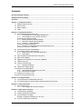
List of Tables
Table 1-1: 7SR242 Ordering Options....................................................................................................7
Table 2-1 Summary of 7SR24 Relay Configurations .........................................................................13
Table 6-1 Operation Mode .....................................................................................................................51
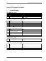
Symbols and Nomenclature
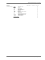
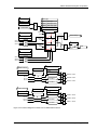
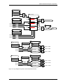
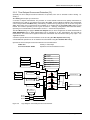
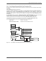
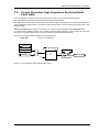
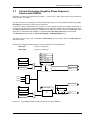
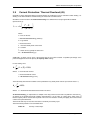
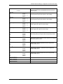
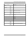
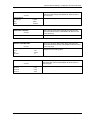
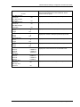
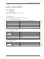
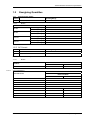
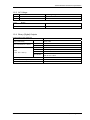
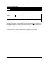
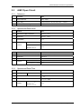
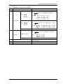
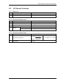
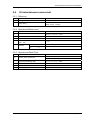
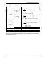
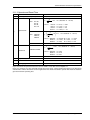
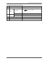
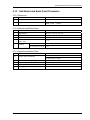
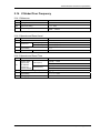
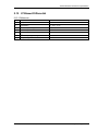
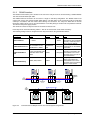
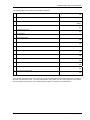
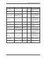
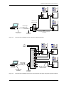
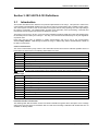
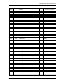
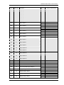
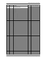
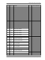
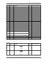
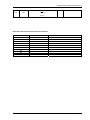
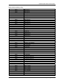
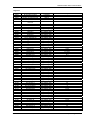
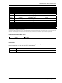
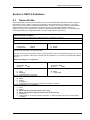
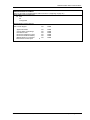
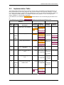
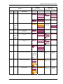
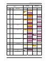
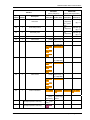
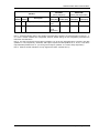
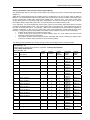
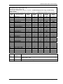
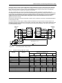
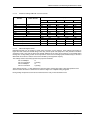
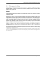
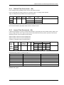
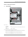
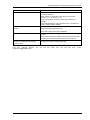
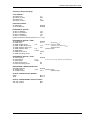
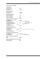
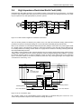
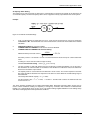
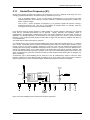
The following notational and formatting conventions are used within the remainder of this document:
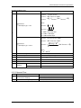
x
Setting Menu Location
MAIN MENU>SUB-MENU
x
Setting:
Elem name -Setting
x
Setting value:
value
x
Alternatives:
[1st] [2nd] [3rd]
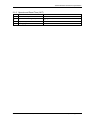
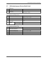
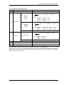
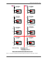
Elem Char Dir
Binary input signal
visible to user
Elem Inhibit
Binary Output visible to user
Elem Starter
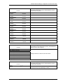
List of settings associated with a specific
function
Appropriate list is TRUE when setting
selected.
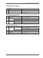
Non-Dir
Forward
Reverse
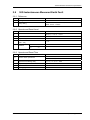
Common setting for multiple functions
Digital signal not visible to
user, to/from another element
Digital signal not visible to
user, internal to this element
Analogue signal with signal
description
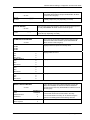
PhaseAFwd
L1 Dir Blk
IL1
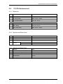
Common control input (c) for multiple
functions. All functions are enabled
when control input is TRUE.
Function.
Elem Reset Delay
c
start
c
trip
start
Individual functions are enabled when
associated control input (c) is TRUE.
c
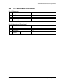
And Gate
(2 inputs shown)
Or Gate
(3 inputs shown)
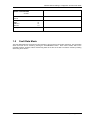
&
t1
EVENT: IEC, Modbus or DNP
Where applicable
Relay instrument
Exclusive Or (XOR) Gate
(3 inputs shown)
trip
EVENT
INST.
1
©2010 Siemens Protection Devices Limited
Chapter 1 Page 5 of 52