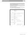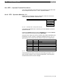
1
CL200 / CL350 / CL400 / CL500
BT-MADAP
Software manual
Edition
101
CL200 / CL350 / CL400 / CL500
BT-MADAP
Software manual
1070 072 163-101 (97.11) GB
1997
by Robert Bosch GmbH, Erbach / Germany
All rights reserved, including applications for protective rights.
Reproduction or distribution by any means subject to our prior written
permission.
Discretionary charge 20,- DM
Contents
1
1.1
1.2
1.3
1.4
1.5
I
Safety Instructions ..................................................................................................................................... 1-1
Proper use ............................................................................................................................................. 1-1
Qualified personnel................................................................................................................................ 1-2
Safety markings on components ........................................................................................................... 1-3
Safety instructions in this manual .......................................................................................................... 1-4
Safety instructions for the described product......................................................................................... 1-5
2
Introduction................................................................................................................................................ 2-1
2.1
Overview................................................................................................................................................ 2-1
2.2
Functions and Features ......................................................................................................................... 2-1
2.3
Sequential Control and Diagnostics Concept ........................................................................................ 2-2
2.4
Menu and Module Structure .................................................................................................................. 2-3
2.4.1
BT20 Menu Tree ............................................................................................................................ 2-4
2.4.2
BT5 Menu Tree .............................................................................................................................. 2-6
2.4.3
CL200 Module Structure................................................................................................................. 2-8
2.4.4
CL350 / CL400 / CL500 Module Structure ..................................................................................... 2-9
3
CL200 Control Functions........................................................................................................................... 3-1
3.1
Introduction ............................................................................................................................................ 3-1
3.2
Definitions .............................................................................................................................................. 3-1
3.2.1
Modules .......................................................................................................................................... 3-1
3.2.2
Markers .......................................................................................................................................... 3-2
3.3
Programming ......................................................................................................................................... 3-3
3.3.1
Module Call..................................................................................................................................... 3-3
3.3.2
Program Structure .......................................................................................................................... 3-4
3.3.3
BTSMADAP Parameter Description............................................................................................... 3-5
3.3.4
Register Contents........................................................................................................................... 3-5
3.3.5
Messages ....................................................................................................................................... 3-6
3.4
Operating Modes ................................................................................................................................... 3-7
3.4.1
Manual Operation / Setup............................................................................................................... 3-7
3.4.2
Inching Mode / Single Step............................................................................................................. 3-8
3.4.3
Semi-automatic Mode .................................................................................................................... 3-9
3.4.4
Automatic Mode............................................................................................................................ 3-10
3.4.5
D6 — Selected Operating Mode................................................................................................... 3-11
3.4.5.1
OpMode Bit Priorities ............................................................................................................ 3-14
3.4.6
D8 — OpMode Message .............................................................................................................. 3-14
3.5
Step Module......................................................................................................................................... 3-17
3.5.1
Diagnostics ................................................................................................................................... 3-19
3.6
Cascade Data Module ......................................................................................................................... 3-20
3.7
Command Output ................................................................................................................................ 3-22
4
CL350 / CL400 / CL500 Control Functions ............................................................................................... 4-1
4.1
Introduction ............................................................................................................................................ 4-1
4.2
Definitions .............................................................................................................................................. 4-1
4.2.1
Modules .......................................................................................................................................... 4-1
4.2.2
Markers .......................................................................................................................................... 4-2
4.3
Programming ......................................................................................................................................... 4-3
4.3.1
Module Call..................................................................................................................................... 4-3
4.3.2
Program Structure .......................................................................................................................... 4-3
4.3.3
KETTE Parameter Description ....................................................................................................... 4-4
4.3.4
Register Contents........................................................................................................................... 4-5
4.4
Operating Modes ................................................................................................................................... 4-6
4.4.1
Manual Operation / Setup............................................................................................................... 4-6
4.4.2
Inching Mode / Single Step............................................................................................................. 4-7
4.4.3
Semi-automatic Mode .................................................................................................................... 4-8
4.4.4
Automatic Mode.............................................................................................................................. 4-9
1070 072 163-101 (97.11) GB
II
Contents
4.4.5
D6 — Selected Operating Mode................................................................................................... 4-10
4.4.5.1
OpMode Bit Priorities ............................................................................................................ 4-13
4.4.6
D8 — OpMode Message .............................................................................................................. 4-13
4.5
Step Module......................................................................................................................................... 4-16
4.5.1
Diagnostics ................................................................................................................................... 4-18
4.6
Cascade Data Module ......................................................................................................................... 4-19
4.7
Command Output ................................................................................................................................ 4-21
5
BTSMADAP & BTS_ZV Function Modules ............................................................................................... 5-1
5.1
BTSMADAP Function Module................................................................................................................ 5-1
5.1.1
Module Functions ........................................................................................................................... 5-1
5.2
BTSMADAP Function Module for CL200............................................................................................... 5-2
5.2.1
Prerequisites and Allocations ......................................................................................................... 5-2
5.2.2
Description of Parameters .............................................................................................................. 5-2
5.3
BTSMADAP Function Module for CL400 / CL500 ................................................................................. 5-3
5.3.1
Prerequisites and Allocations ......................................................................................................... 5-3
5.3.2
Description of Parameters .............................................................................................................. 5-3
5.3.3
DIAG500E Diagnostic Messages ................................................................................................... 5-4
5.4
BTS_ZV Function Module...................................................................................................................... 5-7
5.4.1
Module Functions ........................................................................................................................... 5-7
5.4.2
Calling the BTS_ZV Function Module ............................................................................................ 5-7
5.4.2.1 Description of Parameters .......................................................................................................... 5-7
5.4.2.2 CL350 / CL400 / CL500 — Allocation of Synchronization Results.............................................. 5-9
6
DM255 / 254 / 120 Data Modules.............................................................................................................. 6-1
6.1
BTS_Diag Diagnostics Data Module (DM254) ...................................................................................... 6-1
6.2
Komm_DB Communication Data Module (DM255)............................................................................... 6-2
6.3
DM120 Data Module .............................................................................................................................. 6-4
6.3.1
Automatic Diagnostic Range .......................................................................................................... 6-5
6.3.2
Control Flags .................................................................................................................................. 6-6
6.3.3
Cascade Information Structure....................................................................................................... 6-8
6.3.4
Manual Diagnostic Range .............................................................................................................. 6-8
7
BT5 Menu Description............................................................................................................................... 7-1
7.1
Startup Screen ....................................................................................................................................... 7-1
7.2
Setup Menu............................................................................................................................................ 7-2
7.3
Diagnostic Function ............................................................................................................................... 7-3
7.3.1
Cascade Status .............................................................................................................................. 7-3
7.3.2
Criteria Display ............................................................................................................................... 7-5
7.3.3
Explanation of Terms ..................................................................................................................... 7-7
7.4
BT 20 Main Menu................................................................................................................................... 7-9
7.4.1
Display Mask Group Branching Menu .......................................................................................... 7-10
7.4.1.1 Display Mask Groups................................................................................................................ 7-11
7.4.2
Operation Mask Branching Menu ................................................................................................. 7-12
7.4.2.1 Operation Mask Groups............................................................................................................ 7-13
7.4.3
Message Menu ............................................................................................................................. 7-15
7.4.3.1 Status Messages ...................................................................................................................... 7-15
7.4.3.2 Serial Messages ....................................................................................................................... 7-15
7.4.3.3 Message Parameters................................................................................................................ 7-16
7.5
Service Menu ....................................................................................................................................... 7-18
7.5.1
PG Communication Mask............................................................................................................. 7-18
7.5.2
Power-Up Conditions.................................................................................................................... 7-19
7.5.3
Operand Status Branching Menu ................................................................................................. 7-20
7.5.3.1 Operand Status Display ............................................................................................................ 7-21
7.5.4
Internal Messages ........................................................................................................................ 7-22
7.5.5
Date / Time ................................................................................................................................... 7-22
1070 072 163-101 (97.11) GB
Contents
III
8
BT20 Menu Descriptions ........................................................................................................................... 8-1
8.1
Startup Screen....................................................................................................................................... 8-2
8.2
Setup Menu ........................................................................................................................................... 8-3
8.3
Diagnostic Function ............................................................................................................................... 8-4
8.3.1
Cascade Status .............................................................................................................................. 8-4
8.3.2
Criteria Analysis.............................................................................................................................. 8-5
8.3.3
Explanation of Terms ..................................................................................................................... 8-7
8.4
BT20 Main Menu ................................................................................................................................... 8-9
8.4.1
Display Mask Group Branching Menu .......................................................................................... 8-10
8.4.1.1 Display Mask Groups................................................................................................................ 8-11
8.4.2
Operation Mask Branching Menu................................................................................................. 8-13
8.4.2.1 Operation Mask Groups............................................................................................................ 8-14
8.4.3
Message Menu ............................................................................................................................. 8-16
8.4.3.1 Status Messages ...................................................................................................................... 8-16
8.4.3.2 Serial Messages ....................................................................................................................... 8-17
8.4.3.3 Message Parameters................................................................................................................ 8-18
8.5
Power-Up Conditions ........................................................................................................................... 8-19
8.6
Service Menu....................................................................................................................................... 8-20
8.6.1
Clock / PLC Status Messages...................................................................................................... 8-21
8.6.2
I /O /M /EI /EO Status / Control .................................................................................................... 8-22
8.6.3
Timer / Counter Status ................................................................................................................. 8-24
8.6.4
DM /DF /(DB) Timer / Counter Status .......................................................................................... 8-26
9
TS Programming System .......................................................................................................................... 9-1
9.1
Introduction ............................................................................................................................................ 9-1
9.2
Menu Tree ............................................................................................................................................. 9-1
9.3
TS Programming System Operation...................................................................................................... 9-4
9.3.1
Keyboard and Mouse Operation..................................................................................................... 9-4
9.3.2
Project ............................................................................................................................................ 9-4
9.3.3
Masks ............................................................................................................................................. 9-6
9.3.3.1 Help Text..................................................................................................................................... 9-9
9.3.3.2 Messages.................................................................................................................................. 9-10
9.3.3.3 Text Lists .................................................................................................................................. 9-11
9.3.4
BT5 Operator Terminal — Masks Requiring Editing .................................................................... 9-12
9.3.4.1 BT5 – Operation Mask .............................................................................................................. 9-12
9.3.4.2 BT5 – Power-Up Conditions Mask............................................................................................ 9-13
9.3.4.3 BT5 – Display Mask .................................................................................................................. 9-13
9.3.5
BT20 Operator Terminal — Masks Requiring Editing .................................................................. 9-14
9.3.5.1 BT20 – Operation Mask ............................................................................................................ 9-14
9.3.5.2 BT20 – Power-Up Conditions Mask.......................................................................................... 9-15
9.3.5.3 BT20 – Display Mask ................................................................................................................ 9-16
9.3.6
Variables....................................................................................................................................... 9-17
9.3.7
Parameters ................................................................................................................................... 9-18
9.4
Procedural Description ........................................................................................................................ 9-19
9.4.1
Copying Data From Program Diskette ......................................................................................... 9-19
9.4.2
Loading Project File for Editing..................................................................................................... 9-20
9.4.3
Editing Display Masks .................................................................................................................. 9-21
9.4.4
BT5 — Operator Terminal Procedures ........................................................................................ 9-22
9.4.4.1 BT5 – Operation Mask No. 211 ................................................................................................ 9-22
9.4.4.2 BT5 – Operation Mask No. 212 through 226 ............................................................................ 9-23
9.4.4.3 BT5 – Power-Up Conditions Mask No. 20 ................................................................................ 9-23
9.4.4.4 BT5 – Power-Up Conditions Mask No's. 21-23 ........................................................................ 9-26
9.4.4.5 BT5 – Display Mask No. 110 .................................................................................................... 9-26
9.4.4.6 BT5 – Display Mask No's. 110-113, 120-123, 130-133, 140-143 ............................................. 9-29
1070 072 163-101 (97.11) GB
IV
Contents
9.4.5
BT20 — Operator Terminal Procedures....................................................................................... 9-29
9.4.5.1 BT20 – Operation Mask No. 211 .............................................................................................. 9-29
9.4.5.2 BT20 – Operation Mask No. 212 through 226 .......................................................................... 9-30
9.4.5.3 BT20 – Power-Up Conditions Mask No. 20 .............................................................................. 9-30
9.4.5.4 BT20 – Power-Up Conditions Mask No's. 21-23 ...................................................................... 9-32
9.4.5.5 BT20 – Display Mask No. 110 .................................................................................................. 9-33
9.4.5.6 BT20 – Display Mask No's. 110-113, 120-123, 130-133, 140-143 ........................................... 9-35
9.4.6
Variables....................................................................................................................................... 9-36
9.4.7
Compiling Mask Files ................................................................................................................... 9-37
9.4.8
Transferring .S3 File to Operator Terminal................................................................................... 9-37
10
10.1
10.2
10.3
10.4
10.5
Tesi Mod Software Installation ................................................................................................................ 10-1
Installing the Software.......................................................................................................................... 10-1
English-Language User Interface ........................................................................................................ 10-2
Directory Structure ............................................................................................................................... 10-3
BT-MADAP Program Diskette ............................................................................................................. 10-4
Concluding Remarks ........................................................................................................................... 10-6
11
Appendix.................................................................................................................................................. 11-1
11.1
Examples of Step Modules .................................................................................................................. 11-1
11.1.1
Handling the -STOEM Fault Marker ............................................................................................. 11-1
11.1.2
Using Wait Time ........................................................................................................................... 11-2
11.1.3
Monitoring Time Stop ................................................................................................................... 11-3
11.1.4
Using -VERZW Branching Marker................................................................................................ 11-4
11.2
Characteristic Data of Standard Modules ............................................................................................ 11-6
11.2.1
KETTE200 Cascade Management Module.................................................................................. 11-6
11.2.2
KETTE Function Module .............................................................................................................. 11-6
11.2.3
DIAG500E Diagnostics Module .................................................................................................... 11-7
11.3
Fault Messages ................................................................................................................................... 11-8
11.3.1
BUEP19E Fault Messages – CL200 .......................................................................................... 11-10
11.3.2
BUEP19E Fault Messages – CL350 / CL400 / CL500 ............................................................... 11-11
11.4
BT-MADAP Order Numbers .............................................................................................................. 11-13
1070 072 163-101 (97.11) GB
Safety Instructions
1
1-1
Safety Instructions
Before you start working with the BT-MADAP software, we recommend
that you thoroughly familiarize yourself with the contents of this manual.
Keep this manual in a place where it is always accessible to all users.
1.1
Proper use
This instruction manual presents a comprehensive set of instructions and
information required for the standard operation of the described products.
The products described hereunder
• were developed, manufactured, tested and documented in accordance
with the relevant safety standards. In standard operation, and provided
that the specifications and safety instructions relating to the project
phase, installation and correct operation of the product are followed,
there should arise no risk of danger to personnel or property.
• are certified to be in full compliance with the requirements of the
• COUNCIL DIRECTIVE 89/336/EEC of May 3rd 1989 on the approximation of the laws of the Member States relating to electromagnetic compatibility, 93/68/EEC (amendments of Directives),
and 93/44/EEC (relating to machinery)
• COUNCIL DIRECTIVE 73/23/EEC (electrical equipment designed
for use within certain voltage limits)
• Harmonized standards EN 50081–2 and EN 50082–2
• are designed for operation in an industrial environment (Class A emissions). The following restrictions apply:
• No direct connection to the public low–voltage power supply is
permitted.
• Connection to the medium and/or high–voltage system must be
provided via transformer.
The following applies for application within a personal residence, in
business areas, on retail premises or in a small–industry setting:
• Installation in a control cabinet or housing with high shield attenuation.
• Cables that exit the screened area must be provided with filtering or
screening measures.
• The user will be required to obtain a single operating license issued
by the appropriate national authority or approval body. In Germany,
this is the Federal Institute for Posts and Telecommunications,
and/or its local branch offices.
⇒
This is a Class A device. In a residential area, this device may cause
radio interference. In such case, the user may be required to introduce suitable countermeasures, and to bear the cost of the same.
Proper transport, handling and storage, placement and installation of the
product are indispensable prerequisites for its subsequent flawless service and safe operation.
1070 072 163-101 (97.11) GB
1-2
Safety Instructions
1.2 Qualified personnel
This instruction manual is designed for specially trained personnel. The
relevant requirements are based on the job specifications as outlined by
the ZVEI and VDMA professional associations in Germany. Please refer
to the following German–Language publication:
Weiterbildung in der Automatisierungstechnik
Publishers: ZVEI and VDMA Maschinenbau Verlag
Postfach 71 08 64
60498 Frankfurt/Germany
Interventions in the hardware and software of our products not described
in this instruction manual may only be performed by our skilled personnel.
Unqualified interventions in the hardware or software or non–compliance
with the warnings listed in this instruction manual or indicated on the
product may result in serious personal injury or damage to property.
Installation and maintenance of the products described hereunder is the
exclusive domain of trained electricians as per IEV 826–09–01 (modified)
who are familiar with the contents of this manual.
Trained electricians are persons of whom the following is true:
• They are capable, due to their professional training, skills and expertise, and based upon their knowledge of and familiarity with applicable
technical standards, of assessing the work to be carried out, and of
recognizing possible dangers.
• They possess, subsequent to several years’ experience in a comparable field of endeavour, a level of knowledge and skills that may be
deemed commensurate with that attainable in the course of a formal
professional education.
With regard to the foregoing, please read the information about our comprehensive training program. The professional staff at our training centre
will be pleased to provide detailed information. You may contact the centre by telephone at (+49) 6062 78–258.
1070 072 163-101 (97.11) GB
Safety Instructions
1.3 Safety markings on components
DANGER! High voltage!
DANGER! Corrosive battery acid!
CAUTION! Electrostatically sensitive components!
Disconnect mains power before opening!
Lug for connecting PE conductor only!
Functional earthing or low–noise earth only!
Screened conductor only!
1070 072 163-101 (97.11) GB
1-3
1-4
Safety Instructions
1.4 Safety instructions in this manual
DANGEROUS ELECTRICAL VOLTAGE
This symbol warns of the presence of a dangerous electrical voltage.
Insufficient of lacking compliance with this warning can result in personal injury.
DANGER
This symbol is used wherever insufficient or lacking observance of this
instruction can result in personal injury.
CAUTION
This symbol is used wherever insufficient or lacking observance of instructions can result in damage to equipment or data files.
⇒
This symbol is used to alert the user to an item of special interest.
1070 072 163-101 (97.11) GB
Safety Instructions
1-5
1.5 Safety instructions for the described product
DANGER
Fatal injury hazard through ineffective Emergency–OFF devices!
Emergency–OFF safety devices must remain effective and accessible during all operating modes of the system. The release of
functional locks imposed by Emergency–OFF devices must never
be allowed to cause an uncontrolled system restart! Before restoring power to the system, test the Emergency–OFF sequence!
DANGER
Danger to persons and equipment!
Test every new program before operating the system!
DANGER
Retrofits or modifications may interfere with the safety of the products described hereunder!
The consequences may be severe personal injury or damage to
equipment or the environment. Therefore, any system retrofitting
or modification utilizing equipment components from other manufacturers will require express approval by Bosch.
DANGEROUS ELECTRICAL VOLTAGE
Unless described otherwise, maintenance procedures must always
be carried out only while the system is isolated from the power
supply. During this process, the system must be blocked to prevent an unauthorized or inadvertent restart.
If measuring or testing procedures must be carried out on the active system, these must be carried out by trained electricians.
CAUTION
Danger to the module!
Do not insert or remove the module while the controller is switched
ON! This may destroy the module. Prior to inserting or removing
the module, switch OFF or remove the power supply module of the
controller, external power supply and signal voltage!
CAUTION
Only Bosch–approved spare parts may be used!
1070 072 163-101 (97.11) GB
1-6
Safety Instructions
CAUTION
Danger to the module!
All ESD protection measures must be observed when using the
module! Prevent electrostatic discharges!
Observe the following protective measures for electrostatically endangered modules (EEM)!
• The Employees responsible for storage, transport and handling must
be trained in ESD protection.
• EEMs must be stored and transported in the protective packaging
specified.
• Out of principle, EEMs may be handled only at special ESD work stations equipped for this particular purpose.
• Employees, work surfaces and all devices and tools that could come
into contact with EEMs must be on the same potential (e.g. earthed).
• An approved earthing wrist strap must be worn. It must be connected
to the work surface via a cable with integrated 1 MW resistor.
• EEMs may under no circumstances come into contact with objects
susceptible to accumulating an electrostatic charge. Most items made
of plastic belong to this category.
• When installing EEMs in or removing them from an electronic device,
the power supply of the device must be switched OFF.
1.6
Trademarks
All trademarks referring to software that is installed on Bosch products
when shipped from the factory represent the property of their respective
owners.
At the time of shipment from the factory, all installed software is protected
by copyright. Software may therefore be duplicated only with the prior
permission of the respective manufacturer or copyright owner.
MS–DOSr and Windows™ are registered trademarks of Microsoft Corporation.
1070 072 163-101 (97.11) GB
Introduction
2
2-1
Introduction
The BT-MADAP software is the successor of the proven MADAP software packet which was developed for both the CL400 and the CL500
multiple-processor control unit. As an added feature, BT-MADAP supports the CL200 compact control unit.
2.1 Overview
BT-MADAP requires the following hardware components:
• CL200, CL400 or CL500 programmable logic controller (PLC).
• BT5 or BT20 operator terminal
When compared with the familiar MADAP software, BT-MADAP provides
significant advantages providing distinctive cost savings.
BT-MADAP Advantages
• Reduced volume of program code (memory requirements) through direct access to PLC data from the control panel
• Cycle time effectiveness
• No interface module required because access to data is possible via
interface of programming unit.
• Visualization module (diagnostics module) no longer required.
• Omission of above mentioned modules results in space savings in
physical controller construction.
• For the user switching from MADAP to BT-MADAP, the most significant feature is the absolute compatibility of control functions (sequential function program) for the CL400 and CL500 controllers.
2.2 Functions and Features
A brief listing of the major features appears below:
Controlling machine sequences
For up to 60 sequences with 128 steps each, this function assumes the
entire cascade management, complete with MANUAL, INCHING and
AUTOMATIC modes, up to the point of command output. For MANUAL
and AUTOMATIC modes, different conditions can be programmed in
each step.
Machine operation
Ease of operation through 16 preprogrammed screen masks, each handling 8 manual operating functions. Instead of the previous time-consuming
programming routines, only simple parameterization (selection of parameter values) remains to be carried out.
1070 072 163-101 (97.11) GB
2-2
Introduction
Diagnosing Sequencing Faults
All processing sequences can be monitored and diagnosed in both timespecific and peripheral-controlled fashion. In addition, the diagnostic function can be used to cause the current statuses of any cascade sequence,
in conjunction with its operating mode and the current cascade information, to be displayed.
When displaying the cascade information of the screen of the operating
panel, the step indication uses the instruction list (IL) format.
Displaying and Modifying Operand Statuses
The current status of any control operand can be displayed and modified
in different display formats.
Displaying Control Information
Internal controller information, such as CPU Halted, I/O Fixated, Battery
Warning, as well as the system time and the values affecting cycle time
and the selected watchdog function, are indicated.
2.3 Sequential Control and Diagnostics Concept
The concept is based upon the observation that — similar to the operation
of smaller controllers — smaller, more cost-effective operating devices
can be used for the visual presentation of diagnostic data, even for the
more powerful control units. For this reason, the task of a cascade sequence diagnostic function in the form of a software solution consists of
depositing the diagnostic data in a transfer memory buffer for access by
subsequent processing functions. The processing and display of the referred data is handled by the external BT5 and BT20 operating terminals
that are able to read this buffer without requiring assistance. The DM120
data module has been designated as the transfer memory module.
The two main processing tasks, such as:
•
Controller procedures, and
•
Diagnostic functions
are handled, in the case of the CL200, by the KETTE200 cascade management module. With the CL400/CL500, the KETTE function module and
the DIAG500E module assume the control functions. Additional function
modules are required to establish the relevant connections with operating
and display devices. For the BT5 and BT20 operating terminals, the
BTSMADAP and BTS_ZV function modules are available.
In the case of the CL200, the two above mentioned main processing
tasks were implemented in the controller firmware, and therefore do not
burden the application PLC memory. The function is enabled by the KETTE200.PBL module.
1070 072 163-101 (97.11) GB
Introduction
2-3
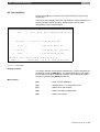
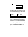
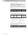
Comparison of Diagnostic Concepts, CL200 vs. CL350 / CL400 / CL500
Definition
CL200
CL350 / CL400 / CL500
Cascade management
For all process sequences, the KETTE200 For each process sequence, a separate module
cascade management module is called up call of the KETTE cascade management moonly in the BTSMADAP function module.
dule must be programmed.
Synchronization
Not implemented.
All cascades in all steps.
Operating Modes Are written directly into the data modules.
Are defined by means of parameters in the
KETTE module.
Diagnostics
As the function is integrated in the KETTE200, it does not require a specific callup.
For all process sequences, the DIAG500E function module is called once by the BTSMADAP
PM.
BT-MADAP
The menu administration is handled by the BT5/BT20 operating terminal. Parameter
processing of standard modules occurs in the PLC program.
Allocation of
KETTE DM's
For the CL200, the binary statuses of both active steps and of command outputs were
omitted.
Marker allocation As the size of the marker address range varies with different controllers, the addresses of
the functionally defined BEFA and WSB markers differ also. The same is true for the scratch
marker range.
Step module
programming
Due to variances between the diagnostics routines of different controllers, in the case of the
CL200 the JPCY jump instruction (never executed) must be entered for non-bit commands.
This is done in order to ensure that, for the purpose of diagnostic functions, such commands
(e.g. default values for monitoring and wait intervals) are ignored. In the case of purely bit
command programming, identical programming routines can be used.
Command output On the CL200, the command output is enabled solely via an actual vs. setpoint value comprogramming
parison of the active step.
Fig. 2-1
Differences in Diagnostics Concepts
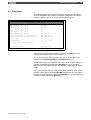
2.4 Menu and Module Structure
As a consequence of differing screen sizes, the utilization of the BT5
and/or BT20 operating terminals results in different menu trees and module structures. The menu trees for BT5 and BT20 appear on the following pages, providing an overview of screen nesting and the respective
function key assignments. (It should be noted that the term mask still appearing in some editing programs, for example, is gradually being replaced by the more common screen.)
1070 072 163-101 (97.11) GB
2-4
Introduction
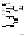
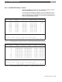
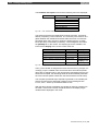
2.4.1 BT20 Menu Tree
M1
Setup Menu
Interface definition, etc.
M2
DIAG = Process sequence diagnostics
Startup Screen
EM10
Cascade Status
EM11
Criteria display
<DIAG>
F1
<<<
F1
<<<
F2
MELD
F3
DIAG
F7
RET
EMnnn
Input/Output screen no. nnn
MMnnn
Message screen no. nnn
Operation:
>?< = Screen-specific
>HOME< = to Main Menu
F8
F9
>>>
ab
<<<
auf
MELD
F3
DIAG
F7
RET
F8
ab
<<<
auf
MELD
H/A
DIAG
K+10
RET
K+1
K-1
>>>
Main Menu
EM4
>F5< MEL calls up status messages
>Anz Display
>Bed Operate
>Meld< Messages
>Ebed< Power-On conditions
>F6< DIAG calls up process sequence and toggles back and forth
< Service
>Serv
< Lamp Test
> LT <
>Cursor< Screen switchover within function groups
between cascade structure and criteria display
<F10> RET Up one menu level
Fx
F9
>>>
F1
F2
F3
F7
<<<
MELD
DIAG
RET
F8
F9
>>>
This key not in use
Display Menu
EM100
F1 DisplGrp1
EM200
Operating Menu
Message Functions
F1 OperGrp1
MM31
F2 DisplGrp2
F2 OperGrp2
F3 DisplGrp3
F3 OperGrp3
F7 DisplGrp4
F7 OperGrp4
F1
F2
F3
F7
<<<
MELD
DIAG
RET
F8
F9
F1
F2
F3
F7
>>>
<<<
MELD
DIAG
RET
MM33
Serial messages
EM30
F8
F9
ZustM
SeriM
>>>
<<<
F5
Display screen group 1 (DisplGrp1)
Operating screen group 1 (OperGrp1)
EM110
EM211
EM111
Status messages
ZustM
SeriM
<<<
F5
Message parameters
ZustM
SeriM
<<<
MELD
F7
DIAG
RET
F8
F9
>>>
EM212
EM112
EM213
EM113
EM214
User or machine-specific entries
Manual operation. 4 lines of 2 movements ea.
Use cursor to select line,
F1
<<<
ab
F1
F2
F3
F7
<<<
MELD
DIAG
RET
EM120-123
F8
F9
<<<
>>>
DisplGrps 2 thru 4
ab
auf
F3
F7
<<<
MEL
DIAG
RET
EM215-218
EM130-133
F8
F9
>>>
OperGrps 2 thru 4
EM219-222
EM140-143
Fig. 2-2
press <<< / >>> to move cursor
EM223-226
Cursor Up/Down:
Toggles screen within a group
Cursor Right/Left move:
Switches screen to adjacent group
BT20 Menu Tree (Part 1)
1070 072 163-101 (97.11) GB
Introduction
2-5
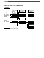
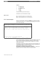
The screen contents are slightly different, and are adapted to the various controller types
(e.g. CL200 without display of data buffer DB).
Power-On Conditions
Service Functions
EM20
EM50
EM21
EM22
EM23
User and machine-specific
entries
> Uh Clock/Internal
<
> E... Status I,O,M,EI,EO
<
> T/Z
T/C
<
>DF/.<
>DBs< DF/DP DMs
F1
F2
F3
F7
<<<
MELD
DIAG
RET
F8
F9
>>>
F1
<<<
F1
F2
F3
F7
<<<
MELD
DIAG
RET
F8
F9
>>>
Cursor Up/Down: Toggles screen within the group
Clock / Internal Messages
Status / Control Functions
EM51
EM60
Statuses (binary)
TT.MM.JJ hh:mm
EM61
Statuses (hex)
I, O, M, EI, EO
I, O, M, EI, EO
Cycle time, battery status
< Cursor >
Fixings, etc.
F1
F2
F3
F7
<<<
MELD
DIAG
RET
F8
F9
F1
F2
F3
T/Z
>>>
<<<
MELD
DIAG
RET
EM70
DF/DP
DBs
F1
F2
F3
T/Z
>>>
<<<
MELD
DIAG
RET
CL400/500 T- and C statuses
EM71
DF/DP
DBs
>>>
CL200 C statuses
CL200 T statuses
CL200
ab
auf
<<<
MELD
EM80/90
EAM
DIAG
F7=C
F7
CL200
DF/DP
RET
DBs
ab
auf
>>>
<<<
MELD
Statuses (hex)
EM81/91
EAM
DIAG
F7=T
F7
DF/DP
RET
DBs
>>>
Statuses (bin)
DM/DF,DB
DM/ DF,DB
< Cursor >
Fig. 2-3
BT20 Menu Tree (Part 2)
1070 072 163-101 (97.11) GB
F1
F2
<<<
MELD
EAM
DIAG
T/Z
RET
DF/DP
DBs
F1
F2
>>>
<<<
MELD
EAM
DIAG
T/Z
RET
DFDP
DBs
>>>
2-6
Introduction
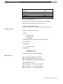
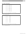
2.4.2 BT5 Menu Tree
M1
Setup Menu
DIAG = Process sequence diagnostics
Interface definition, etc.
M2
Startup Screen
EM10
Cascade status
EM11
Criteria display
<Print
>
F1
F1
F2
F3
F4
EMnnn
Inüut/Output screen
No. nnn
MMnnn
Message screen
No. nnn
Operation:
>?< = Screen-specific info.
F5
F6
ab
F3
F4
F5
F6
ab
auf
H/A
K+10
K+1
K-1
Main Menu
>HOME< = To Main Menu
EM4
>Cursor< Screen switchover within function groups
F1 Display
>F7< Print command calls up cascade structure, and toggles between
cascade structure and criteria display.
F2 Operate
→
Cursor to Service Menu
F3 Messages
>F8< Scrolling; calls up status messages
Fx
auf
F1
F2
F3
F4
F5
LT
This key not in use
Display Menu
EM100
F1
F1 DisplGrp1
F2
EM200
Operating Menu
Message Functions
F1 OperGrp1
MM31
F2 DisplGrp2
F2 OperGrp2
F3 DisplGrp3
F3 OperGrp3
F4 DisplGrp4
F4 OperGrp4
F3
F4
F5
F6
F1
F2
F3
F4
Status messages
MM33
Serial messages
EM30
F5
F6
Zust
Seri
Zust
Seri
Zust
Display screen group 1 (DisplGrp1)
Seri
Para
F4
F5
F6
Operating screen group
(OperGrp1)
EM211
EM110
EM111
EM212
EM112
EM213
EM113
EM214
User and/or
Manual operation. 2 lines of 2 movements ea.
machine-specific
F1
entries
F1
F2
EM120-123
F3
F4
F1
F5
F6
Display screen groups 2 thru 4
Execute move as per line 1
>F2<, >F5<
Execute move as per line 2
EM215-218
EM140-143
Cursor
U
/D Right/Left move:
Cursor
>F1<, >F6<
F1
EM130-133
Fig. 2-4
Message parameters
F2
F3
F4
F5
F6
Operating screen groups 2 thru
4
EM219-222
EM223-226
Toggles screen within a group
Switches screen to adjacent group
BT5 Menu Tree (Part 1)
1070 072 163-101 (97.11) GB
Introduction
2-7
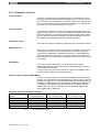
The screen contents are slightly different, and are adapted to the various controller types
(e.g. CL200 without display of data buffer DB).
ServiceMenu
Interface Switching
EM5
EM6
F1 Power-On
conditions
→
Cursor to return to Main Menu
Communication with PG
programming device
enabled!
F2 OPD. status
F3 Clock/Internal mess.
F1
Power-On Conditions
F2
F3
F4
F5
PG
F1
F2
F3
F4
F5
PG
Status / Control Menu
Date / Time
SPS int. Meldungen
F3
I, O, M, EI, EO
EM51
EM52
EM21
F4
T/C
EM22
F5
DF; DB
F6
DMs
EM20
EM50
EM23
User & machine-specific
F1
F2
F3
TT.MM.YY hh:mm
Zykluszeit, Batteriezustand
Fixierungen etc.
F4
F5
F6
F1
F2
F3
F4
F5
F6
entries
F1
F2
F3
F4
F5
F6
Cursor Up/Down: Toggles screen within the group
Status / Control Functions
EM60
Statuses (binär)
I, O, M, EI, EO
EM61
Statuses (hex)
I, O, M, EI, EO
< Cursor >
F1
EM70
F2
F3
DF/DP
DBs
CL400/500 T and C statuses
CL200 T statuses
CL200
ab
T/Z
auf
EM90
EAM
F1
F2
EM71
CL200
DF/DP
DBs
Statuses (hex)
DF, DB
ab
T/Z
DF/DP
DBs
DF/DP
DBs
DFDP
DBs
DF/DP
F6
CL200 C Statuses
F4=Z
F4
F3
auf
EM91
EAM
F4=T
F4
Statuses (bin)
DF, DB
< Cursor >
F1
F2
EM80
EAM
T/Z
DF/DP
DBs
Statuses (hex)
DMs
F1
F2
EM81
EAM
T/Z
Statuses (bin)
DMs
< Cursor >
F1
Fig. 2-5
BT5 Menu Tree (Part 2)
1070 072 163-101 (97.11) GB
F2
EAM
T/Z
DF/DP
F6
F1
F2
EAM
T/Z
F1
F2
F3
F4
F5
F6
2-8
Introduction
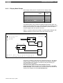
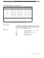
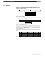
2.4.3 CL200 Module Structure
Administration
module (OM1)
;Oper Modes
CM
::
::
::
CM
-BETRAK1
BETRAK1
Process
Oper Modes
-
BETRAK30
Process
Oper Modes
DM1 = DATENK1
Data Module
for cascade 1
::
;Endlagen and
;Active bits
CM
-BTS_ZV
::
DM30 = DATENK30
Data Module
for cascade 30
PB1 = SCHRK1
Step Program
for cascade 1
BTS ZV
End positions
Aktive Bits
::
PB30 = SCHRK30
Step Program
for cascade 30
;Operating and
;Cascade mgmt.
CM
-BTSMADAP
BTSMADAP
Interface PM to
BT5 and BT20
Terminals
KETTE200
Cascade
Management
and
Step Diagnostics
DM120
Cascades
Diagnostic Data
DM254
Diag. internal Data
;Command
;execution
CM
-BEFAK1
::
::
::
CM
Fig. 2-6
DM255
Status Data
BEFAK1
Command
Execution
::
-BEFAK30
BEFAK30
Command
Execution
CL200 Module Structure
1070 072 163-101 (97.11) GB
Introduction
2.4.4 CL350 / CL400 / CL500 Module Structure
Administration
module (OM1)
;Cascade calls
CM
KETTE1
::
::
::
::
KETTE1
;Oper Modes
;Cascade PM
CM
KETTE
;Command output
::
KETTE60
CM
;End positions and
;Active bits
CM
BTS_ZV
PM1 = SCHRK1
Step Program
for cascade 1
DM1 = DATENK1
Data Module
for cascade 1
::
::
::
::
::
::
::
KETTE60
see above
PM60 = SCHRK60
see above
DM60 = DATENK60
see above
BTS_ZV
End positions
Active Bits
KETTE
Cascade
;Operating
CM
BTSMADAP
BTSMADAP
Interface PM to
to BT5 and BT20
Oper. Terminals
DIAG500E
Step Diagnostics
DM120
Diagnosedaten
DM254
Diag. internal Data
DM255
Status Data
Fig. 2-7
CL350 / CL400 / CL500 Module Structure
1070 072 163-101 (97.11) GB
2-9
2-10
Introduction
1070 072 163-101 (97.11) GB
CL200 Control Functions
3-1
3 CL200 Control Functions
3.1
Introduction
Chapter 2 discusses the control sequence management, including the
different operating modes it provides, plus process organization and
command output functions. Function modules are available to handle the
sequential control, diagnostic functions and display processes.
3.2 Definitions
To ensure orderly sequential processing and/or ascertain the production
of unambiguous diagnostic values, the use of the BT-MADAP software
package shall be governed by the definitions and conventions outlined
below.
3.2.1 Modules
The KETTE200 function module manages a maximum of
•
30 control sequences,
•
containing 128 steps each,
•
with one active step per each cycle.
The following modules are permanently assigned to the above control sequences:
•
Function modules PM1 - PM30 (control sequences)
•
Data modules
DM1 - DM30 (cascade data modules)
Here the PM and DM numbers correspond to the cascade numbers.
Data storage and transfer is handled by the
•
DM120 data module.
1070 072 163-101 (97.11) GB
3-2
CL200 Control Functions
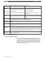
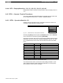
3.2.2 Markers
Within the range of available markers, the markers listed below are assigned a permanent function.
Symbol
BEFA
WSB
STOEM
HALBAUTO
WZT_HLT
WZT
Address
CL200
M191.0
M191.1
M191.2
M191.4
M191.5
M191.6
M191.7
VERZW
M188
Function
Assigned to command output
Assigned to step-on function
Fault marker; fault is indicated by STOEM = 0bin
Step-on in Inching mode also without S+1 transition
Wait time stop
Wait time status
0bin: Wait time running
1bin: Wait time expired
Monitoring time check.
If UEKONTR = 1bin, expiration of monitoring time will not trigger diagnostic function.
Branch address (word)
Step number within the cascade to which branching is to take place if WSB = 1bin.
Fig. 3-1
CL200 Control Functions, Marker Definitions
1070 072 163-101 (97.11) GB
CL200 Control Functions
3-3
3.3 Programming
3.3.1
Module Call
The KETTE200 cascade management module (also referred to as function module) is called only once per PLC cycle in the BTSMADAP function
module, and then services all defined cascade sequences. For this purpose, the number of cascades (i.e., the number of the last cascade sequence to be processed) is transferred to the BTSMADAP function
module as a parameter value. The operating modes are directly written
into the respective data modules. In order to be able to form functional
groups of cascade sequences, it is possible to leave strategic gaps when
creating the cascade data modules. Those cascade sequences for which
no data module was defined will then be skipped, and processing will
continue with the subsequent cascade sequence. In order to exclude step
modules from processing, the operating mode for D6 must be described
as 0hex, in which case the message returned by the module in D0 of the
cascade data module will be 8000hex.
The BTSMADAP.PBL module is called in the OM1 operating module.
BTSMADAP is created with the inclusion of a parameter file which greatly
facilitates calling it during the programming/configuration phase. In the
event that the Call Parameter function is used during programming, the
following program part will appear without requiring additional input:
CM
;
P0
P1
;
-BTSMADAP,2
B -Kett_Anz
B -K200
Fig. 3-2
1070 072 163-101 (97.11) GB
+---+
;<
! Number = No. of last cascade
;<
! KETTE200 module no. as constr.
+---+
CL200 — Calling BTSMADAP Module
3-4
CL200 Control Functions
3.3.2 Program Structure
Organization
module (OM1)
;Operating modes
CM
-BETRAK1
::
::
::
CM
BETRAK1
Oper Mode
processing
-
BETRAK30
Operating mode
processing
DM1 = DATENK1
Data Module
for cascade 1
::
PM1 = SCHRK1
Step Program
for cascade 1
::
DM30 = DATENK30
Data Module
for cascade 30
::
PM30 = SCHRK30
Step Program
;Cascade mgmt.
CM -BTSMADAP
BTSMADAP
KETTE200
module call
KETTE200
Cascade
Management
for cascade 30
and
Step Diagnostics
DM120
Cascades
Diagnostic Data
;Command
;execution
CM
-BEFAK1
BEFAK1
Command
execution
::
::
::
CM
BEFAK30
Command
execution
-BEFAK30
Fig. 3-3
::
CL200 Control Functions — Module Structure
1070 072 163-101 (97.11) GB
CL200 Control Functions
3.3.3
3-5
BTSMADAP Parameter Description
NOTE:
No scratch markers belonging to the range indicated below may be
used as parameters.
M188.0 - M191.7
P0
W
-Kett_Anz
(Input parameter)
Via parameter P0, the BTSMADAP function module receives the number
n of the last cascade sequence for sequence processing as well as diagnostics.
Each cascade sequence being processed utilizes a cascade data module
to store variable data, e.g. current step, monitoring time and wait time.
P1
W
-K200
(Input parameter)
This parameter specifies the module number of the KETTE200 function
module. It corresponds to the function module number in the symbol file.
Subsequent to calling the parameter list, the
"-" symbol character must be deleted. Using K200, the PM200 function
module number is assigned to the KETTE200 function module.
3.3.4
Register Contents
The PLC registers A, B, C, and D, plus the control flags (e.g. RES, Carry)
are not retained beyond the module call. Upon returning from the
BTSMADAP to the calling module, the registers will contain the contents
that are defined as listed in the following table.
Reg.
A
B
C
D
Fig. 3-4
1070 072 163-101 (97.11) GB
Contents
Version number of BTSMADAP module.
Module release date.
No relevance.
No relevance.
BTSMADAP Module, Register Contents
3-6
CL200 Control Functions
3.3.5
Messages
The messages from the KETTE200 module are returned via the
DM254/D510 data word.
The messages comprise error messages that cannot be entered in data
word D0. The status word has the following meaning:
Bit Error and/or Status message
15 Group error indication
14
13
12
11
10
9
8
7
6
5
4
3
2
1
0
Remedy
This bit always occurs in conjunction with one or more of
the bits listed below.
DM120 link is too short
Correct the length of the data module.
Number of cascades from P3 = 0dec
Wrong cascade number for manual diagnosis.
Step module (PMn) not programmed.
DMn link is too short
Enter desired number of cascade sequences.
Correct default; program/integrate PMn and/or DMn.
Program PMn module or remove associated DMn.
Correct length of data module.
The cascade data modules must be integrated with a
length of ≥ 82 bytes.
As deliberate gaps in data module sequences allow the
formation of functional cascade groups, non-existing data
modules will not cause an error to be entered.
If bit 6 is set, bits 0 thru 5 indicate the
last cascade number in which the error
was detected.
Cascade number, bit 5
Cascade number, bit 4
Cascade number, bit 3
Cascade number, bit 2
Cascade number, bit 1
Cascade number, bit 0
Fig. 3-5
NOTE:
Status Message from KETTE200 in DB254/D510
If the DM120 data module was not integrated into the program, the
controller will enter the STOP Mode while returning the Unknown
Module Called message.
1070 072 163-101 (97.11) GB
CL200 Control Functions
3-7
3.4 Operating Modes
For all cascades, the selection of the cascade operating mode (OpMode)
prior to the BTSMADAP module call is effected by writing to the D6 data
word in the respective valid cascade data module. The same applies to
the selection of the wait and monitoring times of the cascades. The D22
(wait time) and D24 (monitoring time) data words are used for this purpose.
3.4.1 Manual Operation / Setup
Function
Manual step operation in consideration of the manual branching conditions.
The step is entered in data word D14 of the associated cascade data
module, and accepted as the current step by means of the Set Step instruction (D6.5=1) in D12.
The command output is enabled when
•
the conditions of the manual branch have been met (BEFA =
1bin, and WSB = 0bin ),
and
•
when the Start (D6.3 ) = 1bin.
On the CL200, the command output occurs via D16 of the associated
cascade data module (see cascade data module).
No step-on is enabled.
Programming
Diagnostics
The Manual mode and Start bits must be statically set to 1bin.
In the DM1 through DM16 screen data modules, the cascade and step
number to be selected (see movement screens) must be entered upwards of data word D32.
Pressing a movement key in a movement screen on the operator terminal
causes the associated cascade data module to be activated by means of
the cascade number, the step number to be entered in D14, and Set Step
(D6.5) and Start (D6.3) to be set to 1bin.
The display in cascade information indicates H ("Hand") for Manual mode
at the corresponding cascade sequence.
Display of all criteria of the manual branch, either of the non-executed
BEFA command output or of the WSB step-on condition branch.
Monitoring and wait times are loaded with the defined values but not
started.
No fault message is returned.
1070 072 163-101 (97.11) GB
3-8
CL200 Control Functions
3.4.2 Inching Mode / Single Step
Function
Step-by-step processing of steps in accordance with conditions of the
automatic branch.
The command output is enabled when
•
the conditions of the automatic branch have been met, (BEFA
= 1bin, and WSB = 0bin), and
•
when the Start (D6.3 ) = 1bin.
The command output is effected via D16 of the associated cascade data
module (see cascade data module).
There is no automatic step-on.
In the case of a positive transition on S+1 (D6.4), if WSB step-on conditions are met, the step-on to the next step will occur.
Programming
The Inching bit is to be statically set to 1 bin. Start = 1bin causes the current
step to be processed, and a positive transition on S+1 causes the step-on
into the subsequent step.
Diagnostics
Display in cascade information indicates T (indicating incremental advance by Touch control) for Inching mode at the corresponding cascade
sequence.
Display of all criteria of the manual branch, either of the non-executed
BEFA or of the WSB branch.
The faulty cascade sequence is displayed.
Monitoring and wait time elapse with the default nominal values.
1070 072 163-101 (97.11) GB
CL200 Control Functions
3-9
3.4.3 Semi-automatic Mode
Function
Semi-automatic processing of steps in accordance with conditions in the
automatic branches.
The command output is enabled when
•
the conditions of the automatic branch have been met (BEFA
= 1bin, and WSB = 0bin), and
•
when the start (D6.3 ) = 1bin.
In the case of the CL200, the command output is effected via D16 of the
associated cascade data module (see cascade data module).
With the WSB step-on conditions met, and the -HALBAUTO (M191.4)
marker set, the step-on occurs automatically. The step-on ends with
the step in which the -HALBAUTO = 0bin marker is located, or if the WSB
step-on condition has not been met.
With a positive transition on S+1 (D6.4), the satisfied WSB step-on conditions will cause the subsequent program sequence to be processed up to
the reset -HALBAUTO marker.
Programming
The Inching bit is to be statically set to 1 bin. Start = 1bin causes the current
step to be processed, and a positive transition on S+1 causes the semiautomatic mode to be started.
Diagnostics
Display in cascade information indicates T (indicating incremental advance by Touch control) for Inching mode at the corresponding cascade
sequence.
Display of all criteria of the manual branch, either of the non-executed
BEFA or of the WSB branch.
The faulty cascade sequence is displayed.
Monitoring and wait time elapse with the default nominal values.
1070 072 163-101 (97.11) GB
3-10
CL200 Control Functions
3.4.4 Automatic Mode
Function
Automatic processing of steps in accordance with conditions in the automatic branches.
The command output is enabled when
•
the conditions of the automatic branch have been met (BEFA
= 1bin, and WSB = 0bin ), and
•
when the start (D6.3 ) = 1bin.
The command output is effected via D16 of the associated cascade data
module (see cascade data module).
If the WSB (step-on conditions) = 1bin, the automatic step-on occurs.
Programming
Automatic mode (D6.2) and Start (D6.3) bits to be statically set to 1 bin.
Diagnostics
Display in cascade information indicates A for Automatic mode at the corresponding cascade sequence.
Display of all criteria of the manual branch, either of the non-executed
BEFA or of the WSB branch.
The faulty cascade sequence is displayed.
Monitoring and wait time elapse with the default nominal values.
1070 072 163-101 (97.11) GB
CL200 Control Functions
3-11
3.4.5 D6 — Selected Operating Mode
Further to the operating modes discussed in the preceding sections, the
D6 data word in the cascade data module contains additional information
relative to operating modes.
D6
nnBaWahl
This data word is written to by the KETTE200 module.
D6.0
D6.1
D6.2
D6.3
D6.4
D6.5
D6.6
D6.7
D7.0
D7.1
D7.2
D7.3
D7.4
D7.5
D7.6
D7.7
Fig. 3-6
D6.0
Manual mode H
Inching mode T
Automatic mode A
Start s
S+1
Set Step
Fault acknowledgement
Reset r
Halt h
WSB does not reset BEFA (Manual mode only)
Fault requires acknowledgement
1
D6 — Selected Operating Mode
Manual Mode
Define Manual mode.
D6.1
Inching Mode
Define Inching mode.
D6.2
Automatic Mode
Define Automatic mode.
D6.3
Start
Start / Command output enable
The bit is valid for all operating modes, and is statically transferred to D6.
If Start = 0bin, the following will occur:
1
•
BEFA is deleted
•
monitoring time is halted
•
wait time continues to elapse
This option applies to the CL200 with firmware version 1.5 and higher.
1070 072 163-101 (97.11) GB
3-12
D6.4
CL200 Control Functions
S+1
Execute the subsequent step.
In INCHING mode, a positive transition of this bit and satisfied step-on
condition (WSB = 1bin) will cause the next step to be executed.
In SEMI-AUTOMATIC mode, a positive transition of this bit, satisfied stepon condition (WSB = 1bin), and with -HALBAUTO marker set, cause the
subsequent cascade sequence to be processed up to the reset HALBAUTO marker.
D6.5
Set Step
Accept preselected step number.
In MANUAL mode, the step prepared in D14 is transferred to the active
step (D12), and subsequently processed.
D6.6
Halt Acknowledgement
Manual fault acknowledgement.
Effective only if D7.7 = 1bin (manual fault acknowledgement).
A positive transition on this bit acknowledges a fault (cascade halted) that
was triggered by an expired monitoring time or by the reset fault marker.
Monitoring and wait times are loaded with the defined values but not
started.
D6.7
Reset
Cascade is reset.
D6.7 = 1bin triggers the following actions:
•
Deletion of active step
•
Reinitialization of cascade sequence
Subsequent to Reset, step 1 is prepared.
D7.0
Halt
Halt cascade sequence processing.
When the bit is set, the cascade is halted, and processing of the current
step continues. For D7.0 = 1bin, the following applies:
•
BEFA is output
•
monitoring time is halted
•
wait time is halted
1070 072 163-101 (97.11) GB
CL200 Control Functions
D7.4
3-13
Step Sequencing
No step-on effected within the same cycle.
Automatic mode only.
D7.6
D7.7
•
If D7.4 = 1bin, only one step is processed per each PLC cycle.
•
If D7.4 = 0bin, the satified WSB step-on condition causes the subsequent step within the same cycle to be activated.
2
WSB does not reset Command Output (BEFA)
Manual mode only.
•
If D7.6 = 1bin, a satisfied WSB step-on condition will not reset the
associated BEFA command output.
•
If D7.6 = 0bin, a satisfied WSB step-on condition will cause the
BEFA command output to be reset.
Acknowledge
Fault acknowledgement
If this bit is set, an occurring cascade fault must be acknowledged by bit
D6.6.
If D7.7 is reset, and the WSB step-on condition is satisfied, the cascade
will auto-acknowledge.
2
This option applies to the CL200 with firmware version 1.5 and higher.
1070 072 163-101 (97.11) GB
3-14
CL200 Control Functions
3.4.5.1 OpMode Bit Priorities
If several operating mode bits are selected simultaneously in data word
D6 of the cascade sequence, processing is subject to the following priority
ranking:
1.
2.
3.
4.
5.
6.
Reset
Halt
Start
Manual
Inching
Automatic
Fig. 3-7
highest priority
↓
↓
↓
↓
lowest priority
OpMode Mode Priorities
3.4.6 D8 — OpMode Message
The D8 data word of each cascade data module contains the return message indicating the operating mode that is enabled once the KETTE200
function module has been processed.
D8
nnBaMldg
D8.0
D8.1
D8.2
D8.3
D8.4
D8.5
D8.6
D8.7
D9.0
D9.1
D9.2
D9.3
D9.4
D9.5
D9.6
D9.7
Fig. 3-8
D8.0
Manual mode H
Inching mode T
Automatic mode A
Start for all operating modes s
Automatic or Inching mode enabled
Wait time elapsing
Reset, cascade is reset r
Halt, cascade is halted h
Fault pulse
Static fault
D8 — Reported OpMode
Manual Mode
The cascade is in Manual mode.
Confirmed by display of symbol H in cascade information of operator terminal.
D8.1
Inching Mode
The cascade is in Inching mode.
Confirmed by display of symbol T in cascade information of operator terminal.
D8.2
Automatic Mode
The cascade is in Automatic mode.
Confirmed by display of symbol A in cascade information of operator terminal.
1070 072 163-101 (97.11) GB
CL200 Control Functions
D8.3
3-15
Start
The cascade has received the start bit.
Confirmed by display of symbol s in cascade information of operator terminal.
D8.4
Automatic / Inching
The cascade is in Automatic or Inching mode.
This bit is used to select whether the manual or automatic branch is to be
processed in the step module.
D8.4 = 1bin, Automatic OR Inching mode is enabled.
D8.4 = 0bin, Manual mode is enabled.
D8.6
Wait Time Running
If the bit is set, this indicates that the wait time for this step has expired.
Prior to calling the step, the cascade management module causes the
status of bit D8.6 to be simultaneously written to the WZT wait time halt
marker (M191.6), making the wait time available to the steps as a diagnoseable operand.
If the wait time has expired, the query:
•
A
B -WZT (wait time)
returns the value of 1bin.
D8.7
Cascade Reset
The cascade is reset, and the active step deleted (D12 = 1bin subsequent
to Reset).
D9.0
Cascade Stopped
The cascade is in Stop mode.
This operating mode is enabled by the following:
D9.6
•
D7.0 = 1bin (Stop),
•
Fault marker M191.2 reset, or
•
Fault in Automatic mode with monitoring time expired (only with
manual acknowledgement via D7.7 = 1bin).
Fault Pulse
Returns a pulse for a PLC cycle in the event that a fault was detected.
Fault criteria are as follows:
•
Reset fault marker
or
•
1070 072 163-101 (97.11) GB
Expired monitoring time.
3-16
D9.7
CL200 Control Functions
Static Fault Signal
Returns a static signal in the event that a fault was detected (criteria
similar to D9.6).
The bit is reset by:
•
Fault acknowledgement
or
•
an action subsequent to a change of operating mode (e.g. Set Step
in Manual mode).
1070 072 163-101 (97.11) GB
CL200 Control Functions
3-17
3.5 Step Module
For each cascade, a step module named -SCHRKn (1 ≤ n ≤ 30) is created.
The step module contains the following for all controller types:
•
the jump distributor to the active step, and
•
a maximum of 128 steps.
The processing of the step module always begins with the line of the jump
distributor belonging to the active step. From here, the jump to the actual
step conditions takes place. Only the active step is processed.
As a rule, the step consists of two independent program parts:
•
the manual part with the manual conditions,
and
•
the automatic part with the conditions for automatic and inching
conditions.
Both parts must be separately and independently concluded with the EM
end module instruction.
In the event that the same conditions exist for the manual and automatic
part, only one branch needs to be programmed.
Both the manual and the automatic part are again separated into:
•
a command output (BEFA) branch, and
•
step-on condition (WSB) branch.
Any number of BEFA and WSB branches can be programmed within a
given step.
In the process of diagnosing sequencing faults, the first non-satisfied
BEFA branch subsequent to the beginning of the step is indicated. If all
BEFA branches are satisfied, the first non-satisfied WSB branch is indicated.
Basic Precepts
1070 072 163-101 (97.11) GB
♦
Only unconditional jumps may be programmed in the jump distributor. The jump sequence must correspond to the sequence of jump
destinations.
♦
Prior to the jump distributor, other instructions are not permitted.
The first instruction of the jump distributor must be JP
[A].
♦
The jump distributor may not be interrupted by extraneous instructions.
♦
The number of jumps in the jump distributor must correspond to the
number of configured steps.
If this is not the case, no diagnostics will be possible.
♦
A module call from within a -SCHRKn step module is not permitted.
♦
The jump distributor and/or the jump destination in the
-SCHRKn step module may not be changed and/or modified with the
use of the Replace function in the monitor program.
3-18
CL200 Control Functions
The KETTE200 function module ensures that the step is always called
with the Carry flag reset. For this reason, the JPCY jump instruction that
is inserted only for diagnostic purposes is never executed, and the consequence is a linear program process.
All instructions from the instruction set of the CL200 are permitted within
the range between the jump instruction and the diagnoseable links (subsequent to the jump destination).
In the event that only bit links occur during a given step, the JPCY jump
can be omitted (as demonstrated here in step 2).
The structure of a step module for the CL200 appears as follows:
JP
JP
JP
:
JP
[A]
-Schritt1
-Schritt2
:
-Schrittn
-Schritt1
JPCY
-VERKN1
; for diagnostic module only
; Change of wait time for this step only
L
W
Kxxx,A
T
W
O,D18
; Change of monitoring time for this step only
L
W
Kyyy,A
T
W
O,D20
; Transfer of branching address
L
W
Kzzz,A
T
W
O,M188
; Branching of Manual & Automatic mode
-VERKN1
L
W
D8,A
; branch selection
A
B
O.4
JPC
-AUTO
; Automatic branch? -> Yes
; Links for Manual mode
A
B
I0.0
=
B
-BEFA
A
B
I0.1
=
B
-WSB
EM
; Mandatory requirement
; for end of step.
1070 072 163-101 (97.11) GB
CL200 Control Functions
3-19
; Links for Automatic and Inching mode
-AUTO
A
B
I0.6
=
B
-BEFA
A
B
I0.7
=
B
-WSB
; Mandatory requirement
EM
; for end of step.
A
=
A
=
EM
Fig. 3-9
-Schritt2
B
B
B
B
I0.2
-BEFA
I0.3
-WSB
; Mandatory requirement
; for end of step.
Step Module for CL200
In the event that a given step has identical Manual and Automatic mode
movements, the selection of the operating mode can be omitted (as in
step 2).
3.5.1 Diagnostics
The monitoring function is handled by the KETTE200 function module.
The presence of scratch markers in steps can lead to undefinable diagnostic results (e.g. the wait time also comprises a scratch marker).
1070 072 163-101 (97.11) GB
3-20
CL200 Control Functions
3.6 Cascade Data Module
The cascade data module managing the sequential control provides all
essential system control data.
Symbol
Explanation
Data format
Entry made by:
K: KETTE200
B: BTSMADAP
A: User
D00
D02
D04
D06
D08
D10
D12
D14
D16
D18
D20
D22
D24
D26
D28
D30
D32
nnFehler
nnKettNr
nnSchAnz
nnBaWahl
nnBaMldg
nnSchr-1
nnSchr.
nnSchr.S
nnBefaAus
nn-KWA
nn-KUE
nn-SKWA
nn-SKUE
Fault bits
Cascade number n (1 thru 30)
Number of steps in cascade
OpMode selection
Reported OpMode
Step number, preceding step
Step number, current step
Step number, Set Step instruction
Step number for command output
Actual value, wait time
Actual value, monitoring time
Setpoint value, cascade wait time
Setpoint value, cascade monitoring time
binary
decimal
decimal
binary
binary
decimal
decimal
decimal
decimal
dec x 100ms
dec x 100ms
dec x 100ms
dec x 100ms
nnK/S_1L
hex
::
D38
::
nnK/S_4L
hex
A
A
::
D48
::
nnK/S_1R
hex
A
A
::
D54
::
nnK/S_4R
hex
A
A
::
D64
::
D80
::
internal
::
internal
HBy = Cascade no./ LBy = Step no.
to movement screen, line 1 left
as in D32, for movement left
HBy = Cascade no./ LBy = Step no.
to movement screen, line 4 left
as in D40 - D46, reserved for movement
HBy = Cascade no./ LBy = Step no.
to movement screen, line 1 right
as in D48, for movement right
HBy = Cascade no./ LBy = Step no.
to movement screen, line 4 right
as in D56 - D62, reserved for movement
occupied by KETTE200
::
occupied by KETTE200
K
A
A
A
K
K
K
B
K
K/A
K/A
A
A
K
K
K
A
Fig. 3-10
A
K
K
K
CL200 Cascade Data Module
Movement Screen and Data Module Allocations:
Movement screen 211 -> DM1, D32
Movement screen 212 -> DM2, D32, and so forth.
1070 072 163-101 (97.11) GB
CL200 Control Functions
3-21
D0 Data Word Allocation
Bit Error and/or Status Message
15
14
13
12
11
10
9
8
7
6
5
4
3 Faulty / incorrect step conclusion
Fault Correction
Each step must be concluded with the following command sequence:
=
EM
B
WSB
→ Check and correct program code.
2 Step contains opcode that cannot Step could contain load or transfer instructions that cannot be diagbe diagnosed.
nosed.
→ Check and correct program code.
1 Step module (PM) not available. The program module assigned to a defined data module is not available/not found.
→ Ensure that module is linked.
0 Number of steps too high or zero. Number of steps must be > 0 and ≤ 128.
→ Check and correct program code.
Fig. 3-11
Fault Word in CL200 Cascade Data Module
Interpretation of Actual and Setpoint Values
for Wait and Monitoring Time (D18, D22 and D20, D24).
At the point of entry into a new step, the KETTE200 module checks
whether the actual values for wait and monitoring time (D18, D20) have
been set by the application program. In the case of values ≠ 0dez, these
will be interpreted as valid times for the active step. If this is not the case,
the time default values are taken from the setpoint values (D22, D24).
In the event that a wait is defined only within a given step with the use of
D18, data word D22 must still be preset with default value of ≠ 0dez because otherwise the KETTE200 module will not process data word D18.
1070 072 163-101 (97.11) GB
3-22
CL200 Control Functions
3.7 Command Output
It is only logical that the command output occurs directly subsequent to
the call-up of the KETTE200 cascade management module.
This is the intended purpose of the BEFAKn command output modules
(numbers 1 ≤ n ≤ 30) which are called subsequent to the processing of
the BTSMADAP module.
Here the current step is compared as an actual value with the setpoint
constants for the command and, if both are found to be equal, the command enable is given.
If no BEFA command output branch is satisfied within the cascade sequence, data word D16 is deleted.
The following is an example of command output in the BEFAK1 module
for a cascade sequence (SCHRK1) with four steps:
CM
L
DM1
D16,A
; Open Kette1 cascade module
; active output
; Step 1
CPLA W
A
B
=
B
K1,A
C
O1.0
; BEFA for Step 1
; BEFA = 1 ?
; Enable output
; Step 2
CPLA W
A
B
=
B
K2,A
C
O2.0
; BEFA for Step 2
; BEFA = 2 ?
; Enable output
; Step 3
CPLA W
A
B
=
B
K3,A
C
O3.0
; BEFA for Step 3
; BEFA = 3 ?
; Enable output
K4,A
C
O4.0
; BEFA for Step 4
; BEFA = 4 ?
; Enable output
W
; Step 4
CPLA W
A
B
=
B
EM
Fig. 3-12
CL200 — Command Output
The above command output program instructions must be repeated for all
active cascade sequences and for all steps.
1070 072 163-101 (97.11) GB
CL350 / CL400 / CL500 Control Functions
4-1
4 CL350 / CL400 / CL500 Control Functions
4.1 Introduction
Chapter 3 discusses the control sequence management, including the
different operating modes it provides, plus process organization and
command output functions. Function modules are available to handle the
sequential control, diagnostic functions and display processes.
4.2 Definitions
To ensure orderly sequential processing and/or ascertain the production
of unambiguous diagnostic values, the use of the BT-MADAP software
package shall be governed by the definitions and conventions outlined
below.
4.2.1 Modules
The KETTE function module manages a maximum of
•
60 control sequences,
•
containing 128 steps each,
•
with one active step per each cycle.
The following modules are permanently assigned to the above control sequences:
•
Function modules PM1 - PM60 (control sequences)
•
Data modules
DM1 - DM60 (cascade data modules)
Here the PM and DM numbers correspond to the cascade numbers.
Data storage and transfer is handled by the DM120 data module.
1070 072 163-101 (97.11) GB
4-2
CL350 / CL400 / CL500 Control Functions
4.2.2 Markers
Within the range of available markers, the markers listed below are assigned a permanent function.
Symbol
Address
CL400/CL500
BEFA
M255.0
WSB
M255.1
STOEM
M255.2
HALBAUTO M255.4
WZT_HLT M255.5
WZT
M255.6
UEKONTR
M255.7
VERZW
M242
Fig. 4-1
Function
Assigned to command output.
Assigned to step-on function.
Fault marker; fault is indicated by STOEM = 0 bin
Step-on in Inching mode also without S+1 transition.
Wait time stop.
Wait time status
0bin: Wait time running
1bin: Wait time expired
Monitoring time check
If UEKONTR = 1bin, expiration of monitoring time will not trigger diagnostic function.
Branching address (word)
Step number within the cascade to which branching is to take place if WSB = 1bin.
CL400 / CL500 Control Functions, Marker Definitions
1070 072 163-101 (97.11) GB
CL350 / CL400 / CL500 Control Functions
4-3
4.3 Programming
4.3.1 Module Call
The KETTE cascade management module is called within the function
modules designated KETTE1 (PM101) through KETTE60 (PM160), and
then services all defined cascade sequences. The required operating
modes are transferred to the respective parameter of the KETTE module.
In order to be able to form functional groups of cascade sequences, it is
possible to leave strategic gaps when creating the cascade data modules.
Those cascade sequences for which no data module was defined in the
OM1 organization module will then be skipped, and processing will continue with the subsequent cascade sequence. In the event that step modules are to be excluded from processing, the associated cascade module
must be declared as a comment at the time it is called up.
For the CL400 / CL500, the module call is structured as follows:
CM
;
P0
P1
P2
P3
;
-KETTE,4
W
W
W
W
Fig. 4-2
-PM/DM
-BETR
-KUE
-KWA
;
;
;
;
.
+---+
<
!
<
!
<
!
<
!
+---+
Cascade and DM number (1≤
≤n≤
≤60)
Operating mode selection
Time value, monitoring time
Time value, wait time
CL400 / CL500 Calling KETTE Module
4.3.2 Program Structure
Organization
module (OM1)
;Cascade calls
CM
KETTE1
::
::
::
::
CM
KETTE1
;Operating modes
;Cascade PM
PM1 = SCHRK1
Step program
for cascade 1
DM1 = DATENK1
Data module
for cascade 1
CM
KETTE
;Command output
::
::
::
::
::
PM60 = SCHRK60
see above
::
DM60 = DATENK60
see above
::
KETTE60
::
KETTE60
see above
KETTE
Cascade manageFig. 4-3
1070 072 163-101 (97.11) GB
CL400 / CL500 Control Functions — Module Structure
4-4
CL350 / CL400 / CL500 Control Functions
4.3.3
KETTE Parameter Description
NOTE:
No scratch markers belonging to the range indicated below may be
used as parameters.
CL400/CL500
M230.0 - M255.7
P0
W
-PM/DM
(Input parameter)
Via parameter P0, the KETTE cascade management module receives the
current cascade number n for the following modules:
•
Number of step module
SCHRKn
•
Number of cascade data module DMn
Each cascade sequence n being processed utilizes a cascade data module to store variable data, e.g. current step, monitoring time and wait time.
P1
W
-BETR
(Input parameter)
This parameter is used to transfer the selected OpMode (operating mode)
to the KETTE module:
•
P1.0
Manual mode (H)
•
P1.1
Inching mode (T)
•
P1.2
Automatic mode (A)
•
P1.3
Start
•
P1.4
S+1
•
P1.5
Set Step
•
P1.6
Halt acknowledgement
•
P1.7
Reset
•
P1.8
Halt
•
P1.9
Synchronize
•
P1.10
•
P1.11
Generate cascade data module
•
P1.12
No step-on in same cycle
•
P1.13
•
P1.14
WSB does not reset BEFA
•
P1.15
Fault acknowledgement
The KETTE cascade management module writes the OpMode data into
data word D6 (nnBAWAHL) of the associated cascade data module.
When in Manual mode (H), the Start and Set Step command value is
transferred only upon actuating the movement keys on the operator terminal.
P2
W
-KUE
(Input parameter)
Parameter P2 is used to transfer the value for the monitoring time to the
KETTE cascade management module. Unless it is again defined within
the individual steps, this value will remain the same for every step.
The time base is always 100 ms. For example, a default value of
•
P2 W
K20D
will result in a monitoring time of 20 x 100 ms = 2 seconds
1070 072 163-101 (97.11) GB
CL350 / CL400 / CL500 Control Functions
4-5
The maximum monitoring time is 109 minutes.
The monitoring time value is entered into data word D20 of the associated
cascade data module.
P3
W
KWA
(Input parameter)
Parameter P3 is used to transfer the value for the monitoring time to the
KETTE cascade management module. Unless it is again defined within
the individual steps, this value will remain the same for every step.
The time base is always 100 ms. For example, a default value of
•
P3 W
K15D
will result in a monitoring time of 15 x 100 ms = 1.5 seconds
The maximum wait time is 109 minutes.
The wait time value is entered into data word D18 of the associated cascade data module.
4.3.4
Register Contents
The PLC registers A, B, C, and D, plus the control flags (e.g. RES, Carry)
are not retained beyond the module call. Upon returning from the KETTE
cascade management module to the calling module, the registers will
contain the contents that are defined as listed in the following table.
Reg.
A
B
C
D
Contents
Version number of KETTE module.
Fault codes, if cascade data module not generated.
No relevance.
No relevance.
Fig. 4-4
KETTE Module, Register Contents
Fault Codes in Register B
Accu B Contents Fault remedy
FFFFhex
0001hex
0002hex
0004 hex
Fig. 4-5
1070 072 163-101 (97.11) GB
Cascade data module not found
P0 of KETTE module = 0dec
P0 of KETTE module = > 64dec
Cascade data module is too short = < 96dec
Fault Codes in Register B of KETTE Module
4-6
CL350 / CL400 / CL500 Control Functions
4.4 Operating Modes
The operating mode (briefly called OpMode) is transferred via parameter
P1 in the KETTE cascade management module, from where it is mirrored
into data word D6 of the associated cascade data module.
Data word D30 is used for parallel operation of the function module via
interfaces.
The Manual, Inching and Automatic OpModes cannot be operated in parallel.
The following definitions are used for parallel operation:
D6.3 / D30.3Start
D6.5 / D30.5Set Step
D7.1 / D31.1Synchronize, only if D24.2 = 1bin
4.4.1 Manual Operation / Setup
Function
Manual step operation in consideration of the manual branching conditions.
The step is entered in data word D14 of the associated cascade data
module, and accepted as the current step by means of the Set Step instruction (D6.5=1bin) in D12.
The command output is enabled when
•
the conditions of the Manual branch have been met (BEFA = 1bin
and WSB = 0bin ), and
•
when the Start (D6.3 ) = 1bin.
The command output occurs via the data bits of data words D80 through
D94 of the associated cascade data module (see cascade data module).
No step-on is enabled.
Programming
Diagnostics
The Manual mode and Start bits must be statically set to 1bin.
In the DM1 through DM16 screen data modules, the cascade and step
number to be selected (see movement screens) must be entered upwards of data word D32.
Pressing a movement key in a movement screen on the operator terminal
causes the associated cascade data module to be activated by means of
the cascade number, the step number to be entered in D14, and Set Step
(D6.5) and Start (D6.3) to be set to 1bin.
The display in cascade information indicates H ("Hand") for Manual mode
at the corresponding cascade sequence.
Display of all criteria of the manual branch, either of the non-executed
BEFA command output or of the WSB step-on condition branch.
Monitoring and wait times are loaded with the defined values but not
started.
No fault message is returned.
1070 072 163-101 (97.11) GB
CL350 / CL400 / CL500 Control Functions
4-7
4.4.2 Inching Mode / Single Step
Function
Step-by-step processing of steps in accordance with conditions of the
automatic branch.
The command output is enabled when
•
the conditions of the automatic branch have been met, (BEFA =
1bin, and WSB = 0bin), and
•
when the Start (D6.3 ) = 1bin.
The command output occurs via the data bits of data words D80 through
D94 of the associated cascade data module (see cascade data module).
No step-on is enabled.
In the case of a positive transition on S+1 (D6.4), if WSB step-on conditions are met, the step-on to the next step will occur.
Programming
The Inching bit is to be statically set to 1 bin. Start = 1bin causes the current
step to be processed, and a positive transition on S+1 causes the step-on
into the subsequent step.
Diagnostics
Display in cascade information indicates T (indicating incremental advance by Touch control) for Inching mode at the corresponding cascade
sequence.
Display of all criteria of the automatic branch, either of the non-executed
BEFA or of the WSB branch.
The faulty cascade sequence is displayed.
Monitoring and wait time elapse with the default nominal values.
1070 072 163-101 (97.11) GB
4-8
CL350 / CL400 / CL500 Control Functions
4.4.3 Semi-automatic Mode
Function
Semi-automatic processing of steps in accordance with conditions in the
automatic branches.
The command output is enabled when
•
the conditions of the automatic branch have been met (BEFA
= 1bin, and WSB = 0bin), and
•
when the start (D6.3 ) = 1bin.
The command output occurs via the data bits of data words D80 through
D94 of the associated cascade data module (see cascade data module).
With the WSB step-on conditions met, and the -HALBAUTO (M255.4)
marker set, the step-on occurs automatically. The step-on ends with
the step in which the -HALBAUTO = 0bin marker is located, or if the WSB
step-on condition has not been met.
With a positive transition on S+1 (D6.4), the satisfied WSB step-on conditions will cause the subsequent program sequence to be processed up to
the reset -HALBAUTO marker.
Programming
The Inching bit is to be statically set to 1 bin. Start = 1bin causes the current
step to be processed, and a positive transition on S+1 causes the semiautomatic mode to be started.
Diagnostics
Display in cascade information indicates T (indicating incremental advance by Touch control) for Inching mode at the corresponding cascade
sequence.
Display of all criteria of the automatic branch, either of the non-executed
BEFA or of the WSB branch.
The faulty cascade sequence is displayed.
Monitoring and wait time elapse with the default nominal values.
1070 072 163-101 (97.11) GB
CL350 / CL400 / CL500 Control Functions
4-9
4.4.4 Automatic Mode
Function
Automatic processing of steps in accordance with conditions in the automatic branches.
The command output is enabled when
•
the conditions of the automatic branch have been met (BEFA =
1bin, and WSB = 0bin ), and
•
when the start (D6.3 ) = 1bin.
The command output occurs via the data bits of data words D80 through
D94 of the associated cascade data module (see cascade data module).
If the WSB (step-on conditions) = 1bin, the automatic step-on occurs.
Programming
Automatic mode (D6.2) and Start (D6.3) bits to be statically set to 1 bin.
Diagnostics
Display in cascade information indicates A for Automatic mode at the corresponding cascade sequence.
Display of all criteria of the manual branch, either of the non-executed
BEFA or of the WSB branch.
The faulty cascade sequence is displayed.
Monitoring and wait time elapse with the default nominal values.
1070 072 163-101 (97.11) GB
4-10
CL350 / CL400 / CL500 Control Functions
4.4.5 D6 — Selected Operating Mode
Further to the operating modes discussed in the preceding sections, the
D6 data word in the cascade data module contains additional information
relative to operating modes.
D6
nnBaWahl
This data word is written to by the KETTE cascade management module
via parameter P1 (-BETR).
D6.0
D6.1
D6.2
D6.3
D6.4
D6.5
D6.6
D6.7
D7.0
D7.1
D7.2
D7.3
D7.4
D7.5
D7.6
D7.7
Fig. 4-6
D6.0
Manual mode H
Inching mode T
Automatic mode A
Start s
S+1
Set Step
Fault acknowledgement
Reset r
Halt h
WSB does not reset BEFA (Manual only)
Fault requires acknowledgement
D6 — Selected Operating Mode
Manual Mode
Define Manual mode.
D6.1
Inching Mode
Define Inching mode.
D6.2
Automatic Mode
Define Automatic mode.
D6.3
Start
Start / Command output enable
The bit is valid for all operating modes, and is statically transferred to parameter P1 of the KETTE cascade management module.
If Start = 0bin, the following will occur:
•
BEFA is deleted
•
monitoring time is halted
•
wait time continues to elapse
To generate the cascade data modules, and to effect synchronization in
Automatic mode, the Start instruction must be deleted.
1070 072 163-101 (97.11) GB
CL350 / CL400 / CL500 Control Functions
D6.4
4-11
S+1
Execute the subsequent step.
In INCHING mode, a positive transition of this bit and satisfied step-on
condition (WSB = 1bin) will cause the next step to be executed.
In SEMI-AUTOMATIC mode, a positive transition of this bit, satisfied stepon condition (WSB = 1bin), and with -HALBAUTO marker set, cause the
subsequent cascade sequence to be processed up to the reset HALBAUTO marker.
D6.5
Set Step
Accept preselected step number.
In MANUAL mode, the step prepared in D14 is transferred to the active
step (D12), and subsequently processed.
D6.6
Halt Acknowledgement
Manual fault acknowledgement.
Effective only if D7.7 = 1bin (manual fault acknowledgement).
A positive transition on this bit acknowledges a fault (cascade halted) that
was triggered by an expired monitoring time or by the reset fault marker.
Monitoring and wait times are loaded with the defined values but not
started.
D6.7
Reset
Resetting the cascade
D6.7 = 1bin will initiate the following actions:
•
Deletion of active step
•
Reinitialization of cascade sequence
•
Generates new cascade data module
Subsequent to Reset, step 1 is prepared.
D7.0
Halt
Stop cascade progress.
If this bit is set, the cascade is stopped, and the current step continues to
be processed. For D7.0 = 1bin, the following applies:
1070 072 163-101 (97.11) GB
•
BEFA is output
•
monitoring time is halted
•
wait time is halted
4-12
D7.1
CL350 / CL400 / CL500 Control Functions
Synchronize
Cascade is synchronized.
This option is available in both Manual and Automatic OpModes. For
Automatic mode, D6.3 = 0bin is also required.
If this bit is set, the KETTE cascade management module searches the
cascade for satisfied preconditions, and synchronizes the step processing
procedure in accordance with the selected OpMode.
The following comprise the preconditions for a successful synchronization:
•
BEFA = 1bin, and
•
WSB = 0bin
For all steps that meet the preconditions for synchronization, the bit associated with the respective step is set in the data block comprising D48
through D62.
In the event that in Automatic mode exactly one step is found that meets
the preconditions for synchronization, this step will be prepared.
In the case of AND branches, because the cascades are viewed independent of each other, the options for synchronization with Automatic
mode are limited.
D7.3
Learning
Generate cascade data module
The KETTE cascade management module generates the data for the
cascade data modules when one of the following conditions applies:
Bit D7.3 is set; subsequent to program loading, subsequent Power-On of
controller, or subsequent to Reset. This cascade-specific data is determined on the basis of the associated step modules, and the parameter
settings of the KETTE module. As a prerequisite for this, D6.3 = 0bin must
be true.
D7.4
Step Sequencing
No step-on effected within the same cycle.
Automatic mode only.
D7.6
•
If D7.4 = 1bin, only one step is processed per each PLC cycle.
•
If D7.4 = 0bin, the satisfied WSB step-on condition causes the subsequent step within the same cycle to be activated.
WSB does not reset Command Output (BEFA)
Manual mode only.
•
If D7.6 = 1bin, a satisfied WSB step-on condition will not reset the
associated BEFA command output.
•
If D7.6 = 0bin, a satisfied WSB step-on condition will cause the
BEFA command output to be reset.
1070 072 163-101 (97.11) GB
CL350 / CL400 / CL500 Control Functions
D7.7
4-13
Acknowledge
Fault acknowledgement
If this bit is set, an occurring cascade fault must be acknowledged by bit
D6.6.
If D7.7 is reset, and the WSB step-on condition is satisfied, the cascade
will auto-acknowledge.
4.4.5.1 OpMode Bit Priorities
If several operating mode bits are selected simultaneously in data word
D6 of the cascade sequence, processing is subject to the following priority
ranking:
1.
2.
3.
4.
5.
6.
Reset
Halt
Start
Manual
Inching
Automatic
Fig. 4-7
highest priority
↓
↓
↓
↓
lowest priority
OpMode Mode Priorities
4.4.6 D8 — OpMode Message
The D8 data word of each cascade data module contains the return message indicating the operating mode that is enabled once the KETTE cascade management module has been processed.
D8
nnBaMldg
D8.0
D8.1
D8.2
D8.3
D8.4
D8.5
D8.6
D8.7
D9.0
D9.1
D9.2
D9.3
D9.4
D9.5
D9.6
D9.7
Fig. 4-8
D8.0
Manual mode H
Inching mode T
Automatic mode A
Start for all operating modes s
Automatic or Inching mode enabled
Synchronization in progress
Wait time elapsing
Reset, cascade is reset r
Halt, cascade is halted h
No synchronization possible
More than one step with BEFA = 1bin, synchronization
Cascade data module generated
Fault pulse
Static fault
D8 — Reported OpMode
Manual Mode
The cascade is in Manual mode.
Confirmed by display of symbol H in cascade information of operator terminal.
1070 072 163-101 (97.11) GB
4-14
D8.1
CL350 / CL400 / CL500 Control Functions
Inching Mode
The cascade is in Inching mode.
Confirmed by display of symbol T in cascade information of operator terminal.
D8.2
Automatic Mode
The cascade is in Automatic mode.
Confirmed by display of symbol A in cascade information of operator terminal.
D8.3
Start
The cascade has received the start bit.
Confirmed by display of symbol s in cascade information of operator terminal.
D8.4
Automatic / Inching
The cascade is in Automatic or Inching mode.
This bit is used to select whether the manual or automatic branch is to be
processed in the step module.
D8.4 = 1bin, Automatic OR Inching mode is enabled.
D8.4 = 0bin, Manual mode is enabled.
D8.5
Synchronization in Progress
The cascade is being synchronized, confirming this status by indicating
D8.5 = 1bin.
D8.6
Wait Time Running
If the bit is set, this indicates that the wait time for this step has expired.
Prior to calling the step, the cascade management module causes the
status of bit D8.6 to be simultaneously written to the WZT wait time halt
marker (M255.6), making the wait time available to the steps as a diagnoseable operand.
If the wait time has expired, the query:
•
A
B -WZT (wait time)
returns the value of 1bin.
D8.7
Cascade Reset
The cascade is reset, and the active step deleted (D12 = 1bin subsequent
to Reset).
D9.0
Cascade Stopped
The cascade is in Stop mode.
This operating mode is enabled by the following:
•
D7.0 = 1bin (Stop)
•
Fault marker M255.2 reset, or
•
Fault in Automatic mode with monitoring time expired (only with
manual acknowledgement via D7.7 = 1bin).
1070 072 163-101 (97.11) GB
CL350 / CL400 / CL500 Control Functions
D9.1
4-15
Synchronization Not Possible
The synchronization conditions:
•
BEFA = 1bin, and
•
WSB = 0bin
are not met in or by any step.
D9.2
More Than One Sync Step
In the process of synchronizing in Automatic mode, more than one step
was found in which the conditions BEFA = 1bin and WSB = 0bin were true.
The synchronized start of the Auto Continue automatic mode is not possible.
D9.3
Cascade Data Module Generated
If D9.3 = 1bin is true, this indicates that the learning cycle or generation of
the cascade data module has been concluded.
Fault Pulse
Returns a pulse for a PLC cycle in the event that a fault was detected.
Fault criteria are as follows:
•
Reset fault marker
or
•
D9.7
Expired monitoring time.
Static Fault Signal
Returns a static signal in the event that a fault was detected (criteria
similar to D9.6).
The bit is reset by:
•
Fault acknowledgement
or
•
1070 072 163-101 (97.11) GB
an action subsequent to a change of operating mode (e.g. Set Step
in Manual mode).
4-16
CL350 / CL400 / CL500 Control Functions
4.5 Step Module
For each cascade, a step module named -SCHRKn (1 ≤ n ≤ 60) is created.
The step module contains the following for all controller types:
•
the jump distributor to the active step, and
•
a maximum of 128 steps.
The processing of the step module always begins with the line of the jump
distributor belonging to the active step. From here, the jump to the actual
step conditions takes place. Only the active step is processed.
As a rule, the step consists of two independent program parts:
•
the manual part with the manual conditions, and
•
the automatic part with the conditions for automatic and inching
conditions.
Both parts must be separately and independently concluded with the EM
end module instruction.
In the event that the same conditions exist for the manual and automatic
part, only one branch needs to be programmed.
Both the manual and the automatic part are again separated into:
•
a command output (BEFA) branch, and
•
step-on condition (WSB) branch.
Any number of BEFA and WSB branches can be programmed within a
given step.
In the process of diagnosing sequencing faults, the first non-satisfied
BEFA branch subsequent to the beginning of the step is indicated. If all
BEFA branches are satisfied, the first non-satisfied WSB branch is indicated.
Basic Precepts
♦
Only unconditional jumps may be programmed in the jump distributor. The jump sequence must correspond to the sequence of jump
destinations.
♦
Prior to the jump distributor, other instructions are not permitted.
The first instruction of the jump distributor must be JP
[A].
♦
The jump distributor may not be interrupted by extraneous instructions.
1070 072 163-101 (97.11) GB
CL350 / CL400 / CL500 Control Functions
♦
Only jump instructions or comments may be inserted between the
command
SP
[A]
and the 1st jump destination. Network branch identifiers are not
permitted here.
♦
The number of jumps in the jump distributor must correspond to the
number of configured steps.
If this is not the case, no diagnostics will be possible.
♦
A module call from within a -SCHRKn step module is not permitted.
♦
The jump distributor and/or the jump destination in the
-SCHRKn step module may not be changed and/or modified with the
use of the Replace function in the monitor program.
♦
Non-bit instructions (e.g. links, time manipulation) must be programmed at the beginning of a branch.
The structure of a step module appears as follows:
JP
JP
JP
:
JP
[A]
-Schritt1
-Schritt2
:
-Schrittn
-Schritt1
; Change of wait time for this step only
L
W
Kxxx,A
T
W
O,D18
; Change of monitoring time for this step only
L
W
Kyyy,A
T
W
O,D20
; Transfer of branching address
L
W
Kzzz,A
T
W
O,M242
; Branching of Manual & Automatic mode
L
W
D8,A
; branch selection
A
B
O.4
JPM
-AUTO
; Automatic branch? -> Yes
; Links for Manual mode
A
B
E0.0
=
B
-BEFA
A
B
E0.1
=
B
-WSB
EM
; Mandatory requirement
; for end of step.
; Links for Automatic and Inching mode
-Schritt2
A
B
I0.6
=
B
-BEFA
A
B
I0.7
=
B
-WSB
; Mandatory requirement
EM
; for end of step.
1070 072 163-101 (97.11) GB
4-17
4-18
CL350 / CL400 / CL500 Control Functions
A
=
A
=
EM
Fig. 4-9
-Schritt2
B
B
B
B
I0.2
-BEFA
I0.3
-WSB
; Mandatory requirement
; for end of step.
Step Module for CL400 / CL500
In the event that a given step has identical Manual and Automatic mode
movements, the selection of the operating mode can be omitted (as in
step 2).
4.5.1 Diagnostics
The machine is monitored by the DIAG500E module.
The presence of scratch markers in steps can lead to undefinable diagnostic results (e.g. the wait time also comprises a scratch marker).
1070 072 163-101 (97.11) GB
CL350 / CL400 / CL500 Control Functions
4-19
4.6 Cascade Data Module
The cascade data module managing the sequential control provides all
essential system control data.
D00
D02
D04
D06
D08
D10
D12
D14
D16
D18
D20
D22
::
D28
D30
D32
::
D46
::
D62
D64
::
D78
D80
::
D94
D100
Symbol
Explanation
Data format
Entry made by:
K: KETTE
B: BTSMADAP
A: User
nnFehler
nnKettNr
nnSchAnz
nnBaWahl
nnBaMldg
nnSchr-1
nnSchr.
nnSchr.S
Fault bits
Cascade number n (1 through 60)
Number of steps in cascade
OpMode selection
Reported OpMode
Step number, preceding step
Step number, current step
Step number, Set Step instruction
binary
decimal
decimal
binary
binary
decimal
decimal
decimal
K
K
K
K
K
K
K
B
dec x 100 ms
dec x 100 ms
K/A
K/A
binary
K
binary
binary
hex
K
K
K
K
K
K
K
K
K
A
hex
A
A
hex
A
A
hex
A
A
nn-KWA
nn-KUE
nnINT0
::
nnINT3
nnBa_Ext
nnINT4
::
nnSyn16
::
nnSyn128
nnSch16
::
nnSch128
nnBef16
::
nnBef128
nnK/S_1L
Actual value, wait time
Actual value, monitoring time
internal use
internal use
internal use
OpMode selection for external operator terminals
internal use
internal use
Synchronization step 1 through 16
::
Synchronization step 113 through 128
Steps 1 through 16
::
Steps 113 through 128
Command output for steps 1 thru 16
::
Command output for steps 113 thru 128
HBy = Cascade no./ LBy = Step no.
to movement screen, line 1 left
::
::
as in D100, for movement left
D106 nnK/S_4L HBy = Cascade no./ LBy = Step no.
to movement screen, line 4 left
::
::
as in D108 - D114, res'd for movement
D116 nnK/S_1R HBy = Cascade no./ LBy = Step no.
to movement screen, line 1 right
::
::
as in D116, for movement right
D122 nnK/S_4R HBy = Cascade no./ LBy = Step no.
to movement screen, line 4 right
::
::
as in D124 - D130, res'd for movement
Fig. 4-10
1070 072 163-101 (97.11) GB
CL400 / CL500 Cascade Data Module
binary
binary
binary
binary
A
4-20
CL350 / CL400 / CL500 Control Functions
Movement Screen and Data Module Assignments:
Movement screen 211 -> DM1, D32
Movement screen 212 -> DM2, D32, and so forth.
D0 Data Word Assignment
Bit Fault and/or Status
message
15 Structural fault in step
module
Fault Correction
The structure of the jump distributor does not correspond with the programmed
step sequence. Step sequence runs correctly but diagnostics not possible.
→ Correct the program structure.
14
13
12
11
10
9
8
7
6
5
4
3 Jump instruction fault
2 Reference list
1 Step module (PB) not
available
0 Number of steps too
high or zero
Fig. 4-11
The 1st instruction in the step module must be the following jump instruction:
SP
[A]
Between this and the 1st jump destination, for example:
-S1
only the jump instruction or comment lines may be inserted.
Attention Networks!
→ Check and correct program code.
The available module is faulty.
→ Recompile and reload program.
The function module assigned by a defined data module is not available.
→ Ensure that module is linked.
Number of steps must be between > 0 and ≤ .
→ Check and correct program code.
Fault Word in CL400 / CL500 Cascade Data Module
Interpretation of Wait and Monitoring Time (D18, D20)
At the point of entry into a new step, the KETTE200 module checks
whether the actual values for wait and monitoring time (D18, D20) have
been set by the application program. In the case of values ≠ 0dec, these
will be interpreted as valid times for the active step. If this is not the case,
the time default values are taken from parameters P2 and P3 of the
KETTE cascade management module.
1070 072 163-101 (97.11) GB
CL350 / CL400 / CL500 Control Functions
4-21
4.7 Command Output
It stands to reason that the command output occurs immediately subsequent to the call-up of the KETTE cascade management module.
This is the intended purpose of the KETTEn modules (numbers 1 ≤ n ≤
60) which handle the command output subsequent to the processing of
the KETTE cascade management module.
For this purpose, the corresponding data word ( D80 - D94 ) for command
output is loaded.
The following is an example of command output for a cascade sequence
(KETTE1) with four steps:
CM
P0
P1
P2
P3
W
W
W
W
-KETTE,4
-PB/DM
-BETR
-KUE
-KWA
;Call cascade management
;Cascade and DM no.
;OpMode selection
;Time value, monitoring time
;Time value, wait time
CM
L
W
DM1
D80,A
; Open Kette1 cascade module
; active output
; Step 1
A
B
=
B
O.0
O1.0
; BEFA = 1 for step 1
; Enable output
; Step 2
A
B
=
B
O.1
O2.0
; BEFA = 1 for step 2
; Enable output
; Step 3
A
B
=
B
O.2
O3.0
; BEFA = 1 for step 3
; enable output
O.3
O4.0
; BEFA = 4 for step 4
; Enable output
; Step 4
A
B
=
B
EM
Fig. 4-12
CL400 / CL500 — Command Output
Subsequent to calling the KETTE cascade management module, the
above command output program instructions must be repeated for all active cascade sequences and for all steps in the corresponding KETTE1
through KETTE60 modules.
1070 072 163-101 (97.11) GB
4-22
CL350 / CL400 / CL500 Control Functions
1070 072 163-101 (97.11) GB
BTSMADAP & BTS_ZV Function Modules
5-1
5 BTSMADAP & BTS_ZV Function Modules
5.1 BTSMADAP Function Module
The BTSMADAP function module prepares the data from the programmable logic controller (PLC) for the operator terminal, and transfers requests issued by the operator terminal to the PLC. The relevant
3
parameterization is almost identical for all controller variants . In the case
of the CL200, the respective module number for the KETTE200 function
module must be taken from the symbol file and transferred to parameter
P1 in the form of a decimal constant. This results in the subsequent module calls discussed in 4.2 and 4.3, below, that can be loaded into the
module editor by means of the Load Parameter List function of the programming device.
5.1.1 Module Functions
The BTSMADAP module
•
controls the manual operation,
•
calls up the diagnostic module,
•
prepares the diagnostic data stored in DM120 for display on the
operator terminal,
and
•
controls the status display,
as well as the
•
status messages.
In order to handle the described tasks, the BTSMADAP module requires
two data modules — one for processing the diagnostic data, and the other
for general communications between operator terminal and PLC.
3
Applies to CL200 with BTSMADAP, version 1.1 and higher.
1070 072 163-101 (97.11) GB
5-2
BTSMADAP & BTS_ZV Function Modules
5.2 BTSMADAP Function Module for CL200
5.2.1 Prerequisites and Allocations
Hardware:
BT5, variant HF000040 and up
BT20, variant HB000400 and up
ZE200, version 1.1 and higher, type 1 front panel
Software:
TesiMod, version 4.0 and higher
KETTE200, version 1.1 and higher
Allocations:
Counter: C0
Scratch markers: M188 through M191
BT Markers, M178 through M188
Data field, DF8196 through DF8190
5.2.2 Description of Parameters
CM
P0
P1
Fig. 5-1
-BTSMADAP,2
W
W
-Kett_Anz
-K200
;
;
;
;
+---+
<
! Number corresponds to the last cascade number
<
! KETTE200 module number as a constant
+---+
Call-up of BTSMADAP Function Module for CL200
P0 -Kett_Anz
At this point the number of the last cascade sequence is entered in the
form of a decimal constant. Gaps in the cascade sequence numbers are
permitted.
Example: Cascade sequences 1 through 5, 7, and 10 through 15 are
available. Therefore, parameter P0 is structured as follows:
•
P0
P1 K200
word
K15
(delete "-" symbol)
Absolute address as decimal constant of the KETTE200 function module
which is internally called from within the BTSMADAP module.
1070 072 163-101 (97.11) GB
BTSMADAP & BTS_ZV Function Modules
5-3
5.3 BTSMADAP Function Module for CL400 / CL500
5.3.1 Prerequisites and Allocations
Hardware:
BT5, variant HF000040 and up
BT20, variant HB000400 and up
ZE400, version 1.2 and higher, front panel 1
SK500, version 102 and higher, front panel 2
with ZS500, version 104 and higher, type 3 front panel, OR
with ZS501, version 103 and higher, type 2 front panel, OR
with ZS510, version 301 and higher, type 1 front panel
Software:
TesiMod, version 4.0 and higher
DIAG500E, version 2.1 and higher
KETTE, version 2.1 and higher
Allocations:
Counter: C0
Scratch markers: M230 through M254
BT Markers: M178 through M188
5.3.2 Description of Parameters
CM
P0
P1
P2
Fig. 5-2
-BTSMADAP,3
W
W
W
-Kett_Anz
-K180
-DIAG500E
;
;
;
;
;
+---+
<
! Number corresponds to the last cascade number
<
! Start addr. in oper. screen, delete "-"
<
! Diagnostics module
+---+
Call-up of BTSMADAP Function Module for CL400 / CL500
P0 -Kett_Anz
At this point, the number of the last cascade sequence is entered in the
form of a decimal constant. Gaps in the chronological sequence of cascade sequence numbers are permitted.
Example: Cascade sequences 1 through 5, 7, and 10 through 15 are
available. Therefore, parameter P0 is structured as follows:
•
P0
word
K15
P1 K180 (delete "-" symbol)
1070 072 163-101 (97.11) GB
5-4
BTSMADAP & BTS_ZV Function Modules
Parameter P1 is used to establish the reference to the movement
screens. The base address is defined as the decimal constant of the
markers used in the movement screens. As a default, the BT-MADAP
module uses the markers from M180 upward. Accordingly, the following
applies to P1:
•
P1
K180
P2 -DIAG500E
Symbolic address of DIAG500E diagnostic module that is internally called
from within the BTSMADAP module.
5.3.3
DIAG500E Diagnostic Messages
Data word DM254/D510 is used to return the messages of the DIAG500E
diagnostic module.
The messages comprise fault messages that cannot be entered in the
cascade data module in data word D0. The status word has the following
meaning:
Bit Cause of Fault
15 Group fault indication.
14 No significance.
13 Number of main station
cascades (P6) > Total
number, cascades (P3).
12 Data module for cascade
not available or too short.
11 No free memory capacity
in data field.
10 Step number too high.
Troubleshooting
At least one of the following faults,
except bit 0, is present:
Number of main station cascades
(P6) > Total number, cascades (P3).
→Correct the parameterization.
The DIAG500E module attempts to
diagnose a cascade sequence but is
either unable to find the corresponding data module, or module is
incomplete.
→Link data modules of correct
length with the program.
BOSCH standard modules occupy
blocks in data fields. A total of 12
data field blocks are available.
→Reduce the total number of callups of BOSCH modules.
The step number to be diagnosed is
128. You may have selected a number larger than 128 in the Manual
mode of the cascade sequence.
1070 072 163-101 (97.11) GB
BTSMADAP & BTS_ZV Function Modules
Bit Cause of Fault
9 Cascade number not permitted with manual diagnostics.
8 Invalid number of cascade
sequences.
7 Fault in system area (system instruction).
6 Structural fault in cascade
sequence jump distributor.
5 Data field address (P7) too
high.
4 Too many conditions in the
branch to be diagnosed.
1070 072 163-101 (97.11) GB
5-5
Troubleshooting
Parameter P2 of DIAG500E module
is not within permitted range between 1 and 64.
→ Modify parameter settings.
Parameter P3 of DIAG500E module
has a value higher than 64. You cannot,
however, process more than the maximum of 64 cascade sequences.
→ Modify parameter settings.
This bit indicates that too many system
instructions (e.g. LAD and TAD) are
being used in the entire PLC program.
→Reduce the number of system instruction calls or utilize sequential call
coordination.
In this context, see also the manual
entitled CL500 System Instructions,
order no. 1070 072 068.
The DIAG500E module has detected
a structural fault in the jump distributor for the cascade sequence.
The cause may be that the step
sequence in the jump distributor
does not correspond to that in the
step program.
→Modify the step sequence either in
the cascade module or in the jump
distributor.
The data field base address has
been defined too high, denying the
requested substations needed space
in the data field area.
→Define a smaller start address.
In the BEFA command output or
WSB step-on condition branch, the
maximum number of 64 conditions
per BEFA or WSB allocation was
exceeded.
→Divide the branch into several
subbranches.
5-6
BTSMADAP & BTS_ZV Function Modules
Bit Cause of Fault
3 Illegal instruction in the
branch to be diagnosed.
2 No significance.
1 No significance.
0 Warning: number of cascades = 0, without group
fault indication.
Fig. 5-3
Troubleshooting
In the BEFA or WSB branch, you gave
user instructions that cannot be diagnosed. You can program these instructions at any time prior or subsequent to
the cascade branches.
→Modify your cascade sequence.
Parameter P3 of the DIAG500E
module has the value of 0.
→Change this value to suit your
application.
DIAG500E Status Message in DB254/D510 Data Word
1070 072 163-101 (97.11) GB
BTSMADAP & BTS_ZV Function Modules
5-7
5.4 BTS_ZV Function Module
The BTS_ZV function module services the end position and active bits in
the operating screens of the BT operator terminals. The parameterization
is identical for all controller variants. The module must be called for each
operating screen that is used. This results in the subsequent module call
(discussed in 4.4.2, below) that can be loaded into the module editor by
means of the Load Parameter List function of the programming device.
5.4.1 Module Functions
The BTS_ZV function module
•
indicates the active end positions, and
•
indicates the active outputs
in the screens used on the operator terminals.
5.4.2 Calling the BTS_ZV Function Module
CM
P0
P1
P2
P3
P4
P5
P6
P7
P8
P9
P10
P11
P12
P13
P14
P15
P16
P17
Fig. 5-4
-BTS_ZV,18
W
W
B
B
B
B
B
B
B
B
B
B
B
B
B
B
B
B
-MASKNR
-K180
-I_Z_1
-O_Z_1
-I_Z_2
-O_Z_2
-I_Z_3
-O_Z_3
-I_Z_4
-O_Z_4
-I_V_1
-O_V_1
-I_V_2
-O_V_2
-I_V_3
-O_V_3
-E_V_4
-O_V_4
;
;
;
;
;
;
;
;
;
;
;
;
;
;
;
;
;
;
;
;
+---+
<
!
<
!
<
!
<
!
<
!
<
!
<
!
<
!
<
!
<
!
<
!
<
!
<
!
<
!
<
!
<
!
<
!
<
!
+---+
Screen no. in which the variables are used.
Start addr. disp'd in oper. screen, delete "-"
EndPosit 1 Z = STRPOS (Start position)
ComdExec 1 Z = STRPOS
EndPosit 2 Z = STRPOS (Start position)
ComdExec 2 Z = STRPOS
EndPosit 3 Z = STRPOS (Start position)
ComdExec 3 Z = STRPOS
EndPosit 4 Z = STRPOS (Start position)
ComdExec 4 Z = STRPOS
EndPosit 1 V = WRKPOS (Work position)
ComdExec 1 V = WRKPOS
EndPosit 2 V = WRKPOS (Work position)
ComdExec 2 V = WRKPOS
EndPosit 3 V = WRKPOS (Work position)
ComdExec 3 V = WRKPOS
EndPosit 4 V = WRKPOS (Work position)
ComdExec 4 V = WRKPOS
Call-up of BTS_ZV Function Module
5.4.2.1 Description of Parameters
If a marker address deviating from the standard is to be used, the corresponding parameterized constant value must be changed accordingly.
This means that changes are also required of the respective parameters
P2 through P17, and of the addresses in the variables file.
Upward of the base address defined with parameter P1, 4 marker bytes
are used.
1070 072 163-101 (97.11) GB
5-8
BTSMADAP & BTS_ZV Function Modules
P0 -MASKNR
In this case, the number of the movement screen is entered in the form of
a decimal constant in which the display of end positions and active bits is
to be accomplished. Each movement screen that is used requires a corresponding module call of the BTS_ZV function module.
Example: Movement mask Hand 1/1 (Manual) is being used. The corresponding screen number (MASKNR) is 211:
•
P0
P1 K180
word
K211
(delete "-")
Parameter P1 is used to establish the reference to the movement
screens. The base address is defined as the decimal constant of the
markers used in the movement screens. As a default, the BT-MADAP
function module uses the markers from M180 upward. Accordingly, the
following applies to P1:
•
P1
K180
Additional Parameters
No.
P2
P3
P4
P5
P6
P7
P8
P9
P10
P11
P12
P13
P14
P15
P16
P17
Fig. 5-5
Bit
B
B
B
B
B
B
B
B
B
B
B
B
B
B
B
B
Abs.addr.
M180.0
M181.0
M180.1
M181.1
M180.2
M181.2
M180.3
M181.3
M182.0
M183.0
M182.1
M183.1
M182.2
M183.2
M182.3
M183.3
Symbol
-E_Z_1
-A_Z_1
-E_Z_2
-A_Z_2
-E_Z_3
-A_Z_3
-E_Z_4
-A_Z_4
-E_V_1
-A_V_1
-E_V_2
-A_V_2
-E_V_3
-A_V_3
-E_V_4
-A_V_4
Explanation
End position display, start position, 1st movement left
Active display, command output, start position, 1st movement left
End position display, start position, 2nd movement left
Active display, command output, start position, 2nd movement left
End position display, start position, 3rd movement left
Active display, command output, start position, 3rd movement left
End position display, start position, 4th movement left
Active display, command output, start position, 4th movement left
End position display, work position, 1st movement left
Active display, command output, work position, 1st movement left
End position display, work position, 2nd movement left
Active display, command output, work position, 2nd movement left
End position display, work position, 3rd movement left
Active display, command output, work position, 3rd movement left
End position display, work position, 4th movement left
Active display, command output, work position, 4th movement left
Parameters P2 through P17 of BTS_ZV Function Module
In the symbol file, the symbolic addresses -I_C_1 through -O_V_4 must
be arranged in a new order in accordance with system requirements. For
example, I10.0 = -I_C_1, and similar modifications are required for additional movement masks.
Unused bit parameters must be set to "logic 0."
1070 072 163-101 (97.11) GB
BTSMADAP & BTS_ZV Function Modules
5-9
5.4.2.2 CL350 / CL400 / CL500 — Allocation of Synchronization Results
As a default, the display of the synchronization results in the movement
screens is assigned to the following markers:
Abs. addr.
Explanation
M184.0
Display of 1st synchronization result, 1st movement left
M184.1
Display of 1st synchronization result, 2nd movement left
M184.2
Display of 1st synchronization result, 3rd movement left
M184.3
Display of 1st synchronization result, 4th movement left
M185.0
Display of 1st synchronization result, 1st movement right
M185.1
Display of 1st synchronization result, 2nd movement right
M185.2
Display of 1st synchronization result, 3rd movement right
M185.3
Display of 1st synchronization result, 4th movement right
Fig. 5-6
CL350 / CL400 / CL500 — Allocation of Synchronization Results
1070 072 163-101 (97.11) GB
5-10
BTSMADAP & BTS_ZV Function Modules
1070 072 163-101 (97.11) GB
DM255 / 254 / 120 Data Modules
6-1
6 DM255 / 254 / 120 Data Modules
6.1 BTS_Diag Diagnostics Data Module (DM254)
The BTS_Diag diagnostics data module is permanently allocated to the
address occupied by DM254. Its data contents are listed below.
BTS_Diag (DM254)
No.
D0
D2
D4
D6
D8
D10
D46
D82
D118
D154
D190
D226
D262
D264
D270
:
D328
D330
:
D388
D390
:
D448
:
D506
D508
D510
Symbol
Explanation
DIAGNOSTIC DATA TRANSFERRED FROM DM120
Cascade no. / Step no.
Faulty, OpMode / Number of criteria
Day / Month
Year / Hour
Minute / Second
DECODED CRITERIA DISPLAY, 18 lines
Krit1
"faulty" symbol
Krit2
Instruction
Krit3
Operand identifiers I/O/M/T/C...
Krit4
Byte address 100's / 10's
Krit5
Byte address 1's / Decimal point
Krit6
Bit address / Blank
Krit7
Operand text code
DIA_Save Stored screen no. for Diagnostics call-up (for RETURN)
Kett_Anw Cascade selection for Manual diagnostics
CASCADE STATUS FOR 60 CASCADES
Step no. for 60 cascades in D270 through D329
1.K_StSn Kette2/Kette1
DIA1
DIA2
DIA3
DIA4
DIA5
Data format
Entry made by:
B: BTSMADAP
A: User
hex
hex
hex
hex
hex
B
B
B
B
B
ASCII
ASCII
ASCII
ASCII
ASCII
ASCII
decimal
decimal
decimal
B
B
B
B
B
B
B
B
B
hex
B
hex
B
hex
B
30K_StBa Kette60/Kette59
Cascade text code for 60 cascades in D390 thru D449
1.K_StTx Kette2/Kette1
hex
B
hex
B
30K_StTx Kette60/Kette59
hex
B
DF_Adr
KopfKett
DiagMldg
hex
hex
hex
A
A
B
30K_StSn Kette60/Kette59
"faulty" identifier and OpMode for 60 cascades
in D330 through D389
1.K_StBa Kette2/Kette1
Parameter P7 in DIAG500E
Parameter P6 in DIAG500E
Status word of parameter P5, DIAG500E
Fig. 6-1
DB254 (BTS_Diag) Data Module Allocation
The servicing of data words D506 and D508 becomes effective only in the
case of decentralized diagnostics with head stations and substations.
1070 072 163-101 (97.11) GB
6-2
DM254 / 255/ 120 Data Modules
6.2 Komm_DB Communication Data Module (DM255)
The Komm_DB communication data module is permanently allocated to
the address occupied by DM255.
Its data contents are listed below.
With the exception of the operator terminal identification in D478, all data
is initialized by the BTSMADAP function module.
Komm_DB (DM255)
No.
Symbol
Explanation
D0
D2
D4
D6
D8
D10
D12
D14
D16
D18
D20
D22
D24
D26
D28
D30
D32
D34
D36
Status1
Status2
Status3
Status4
Status5
Status6
Status7
Status8
Status9
Status10
Status11
Status12
Status13
Status14
Status15
Status17
Status18
Status19
Status20
D40
D42
D44
D46
D48
D50
D52
D54
D56
D58
D60
D62
Save1
Save2
Save3
Save4
Save5
Save6
Save7
Save8
Save9
Save10
Save11
Save12
D64
D66
D68
D70
D72
:
D400
:
D438
Steuern1
Steuern2
STATUS DISPLAY
OPD identifier code DF, DP / I,O,M,EI,EO
DM number
DM length
Byte address, line 1
Byte address, line 2
Byte address, line 3
Byte address, line 4
Byte address, line 5
Byte address, line 6
Byte address, line 7
Byte address, line 8
Value, line 1
Value, line 2
Value, line 3
Value, line 4
Value, line 5
Value, line 6
Value, line 7
Value, line 8
Stored screen switchover addresses
Status I / O
Status EI / M
Status - / EO
Status DF
Status DP
Status D
Control O / I
Control EI / M
Control - / EO
Control DF
Control DP
Control D
OPERAND CONTROL
DM number
Data word/ Operand address
Steuern3
Value
SMerker
Scratch marker range, D400 thru D438
STindBit
Kette+-1
Kette+10
Curpos
INTERNAL DATA
Control fucntions, internal helper bits
Cascade number +-1
Kette +10
Cursor position in movement screens
D440
D442
D444
D446
Data format
hex
decimal
decimal
decimal
decimal
decimal
decimal
decimal
decimal
decimal
decimal
hex
hex
hex
hex
hex
hex
hex
hex
Entry made by:
B: BTSMADAP
A: User
dezimal
hex
hex
hex
hex
B
B
B
B
B
B
B
B
B
B
B
B
B
B
B
B
B
B
B
B
B
B
B
B
B
B
B
B
B
B
B
B
B
B
B
B
B
B
hex
B
hex
B
B
B
B
B
B
hex
hex
hex
decimal
decimal
decimal
hex
hex
hex
decimal
decimal
decimal
hex
hex
hex
hex
1070 072 163-101 (97.11) GB
DM255 / 254 / 120 Data Modules
No.
Symbol
D448
STEU_FRG
D450
D452
D454
D456
D458
Battvorw
Ages/Fix
Watchdog
Zykl_max
Zykl_akt
BT_ZM
Explanation
Control enabled if contents =1 (0: "control
disabled")
INTERNAL PLC MESSAGES
Data format
hex
hex
hex
decimal
decimal
decimal
READ/WRITE AREAS OF BT5 / BT20 TERMINALS
16 (bytes) x 8 status messages (parallel)
Bosch-internal status messages no. 1 thru 16
User status messages, no's. 17 thru 32
User status messages, no's. 33 thru 48
User status messages, no's. 49 thru 64
User status messages, no's. 65 thru 80
User status messages, no's. 81 thru 96
User status messages, no's. 97 thru 112
User status messages, no's. 113 thru 128
D460
D462
D464
D466
D468
D470
D472
D474
D476
D478
D480
D482
D484
D486
D488
D490
D492
BT5?
BT_Uhr
BT5 Application
BT clock, 8 bytes
BT_MskNr
BT_DIP
BT_KO
D494
D496
D498
D500
BT_Poll1
BT_Poll2
BT_Poll3
BT_Poll4
D502
D504
BT_M_loe
BT_Tast
Screen number
DIP switch
Write coordination byte
8 bytes BT polling range
Read coordination byte, / ----Serial message channel
LED 1 thru 8, e.g. bit1=LED On/Off, bit0=flashes
LED 9 thru 16
Clear serial message buffer
with code E216H + 7FFEh on serial message channel
Function key code for operator terminal
Fig. 6-2
binary
binary
binary
binary
binary
binary
binary
binary
hex
hex
hex
hex
hex
hex
decimal
binary
binary
binary
hex
hex
hex
hex
hex
6-3
Entry made by:
B: BTSMADAP
A: User
A
B
B
B
B
B
B
B
B
B
B
B
B
B
B
B
B
B
User
B
B
B
B
B
B
B
B
B
B
B
B
B
B
B
Allocation of Komm_DB Communication Module (DM255)
D478 of the data module defines which operator terminal is connected to
the PLC. With D478=5, a BT5, and with D478=0, a BT20 is declared. In
the event that this identifier is not entered during the operation of the BT5,
the movement function keys (F1, F2, F5, and F6) will be disabled. In the
case of the CL400 / CL500 controllers, the same condition will prevent the
synchronization result (LED in the respective movement keys) to be displayed.
1070 072 163-101 (97.11) GB
6-4
DM254 / 255/ 120 Data Modules
6.3 DM120 Data Module
The DM120 data module is used for the automatic storage of information
about the first-value error message of a cascade in a data range that is
specifically reserved for that purpose (D0 through D148).
Data related to errors occurring in subsequent cascade processing within
the controller can be queried via the manual diagnostics range (D278
through D 410).
DW
HIGH Byte contents
D0
Control flags
D2
AutoD4
DiagD6
nostics
D8
Range
D10
D12
(Fist-value D14
message) D16
D18
:
D142
Manual
Diagnostics
Range
Day
Year
Minute
Weekday (0 = Sunday)
Cascade number
Module type
Cascade status
1. OpCode
2. OpCode
:
64. OpCode
D144
D146
D148
D150
:
D276
Reserved
Reserved
Reserved
1st Cascade information
:
64th Cascade information
D278
D280
D282
D284
:
D410
Cascade number
Module type
Cascade status
1st OpCode
:
64th OpCode
Fig. 6-3
LOW Byte contents
Month
Hour
Second
unused
Step number
Module number
Number of messages
Step number
Module number
Number of messages
DM120 Data Module
♦
For the CL200, the DM120 data module must be opened for the full length
(512).
For application with the CL400 / CL500, opening up to and including D410
(410) will suffice.
1070 072 163-101 (97.11) GB
DM255 / 254 / 120 Data Modules
6-5
6.3.1 Automatic Diagnostic Range
In the event of a fault occurrence, the DIAG500E diagnostics module will
automatically enter diagnostic data into the data words identified below.
The respective data words are then read by BTSMADAP and, subsequent
to processing for display in the BT5 / BT20 operator terminals, will be
written to the BTS_Diag data module (DM254).
Date Format
The system time and date of an occurring first-value error are written to
the data words D2 through D8 in hex notation. The weekday is coded as
follows:
Step Number
•
•
•
•
•
•
•
0 = Sunday
1 = Monday
2 = Tuesday
3 = Wednesday
4 = Thursday
5 = Friday
6 = Saturday
Data byte D10 indicates the step number of the faulty cascade.
Cascade Number
Data byte D11 indicates the cascade number of the faulty cascade.
Module Number
Each cascade is programmed by the user in an associated function module. The number of that function module is stored in data byte D12, and
corresponds to both the cascade number and the cascade data module
number.
Module Type
Data byte D13 indicates the module type of the faulty cascade. In the
case of the CL200, CL400, and CL500, the value of = 1bin, indicating the
function module, is entered here.
Number of Messages
Data byte D14 contains the number of conditions belonging to the firstvalue error. The representation occurs in hex notation. As only the first 64
conditions are stored, the number of messages is set to 65 in the event
that the BEFA command output or WSB step-on condition branch should
consist of more than 64 conditions.
Cascade Status
Data byte D15 indicates the OpMode of the faulty cascade at the time the
first-value error occurred.
•
•
•
1070 072 163-101 (97.11) GB
Bit 0 (value 1) = Cascade in Manual mode
Bit 1 (value 2) = Cascade in Inching mode
Bit 2 (value 4) = Cascade in Automatic mode
6-6
DM254 / 255/ 120 Data Modules
6.3.2 Control Flags
Data word D0 contains the control flags. The individual data bits carry
various default functions.
D0.0
Data bit D0.0 is set to HIGH (1) by the DIAG500E diagnostics module in
the event that a first-value error was entered. Subsequent to the read-out
of the first-value error, this data bit is reset by the BTSMADAP function
module. There exists a functional interrelation between data bits D0.0 and
D0.1.
D0.1
Data bit D0.1 controls the response to an occurring first-value error.
•
D0.1 = 0
Default setting in BT-MADAP
The first-value error is always entered. If an unacknowledged first-value error is stored in the data module, it
will be overwritten by the newly occurring first-value error.
•
D0.1 = 1
User-defined setting
A new first-value error can be entered only if the acknowledgement of a previous first-value error was effected by means of D0.0. If this is not the case, the new
first-value error will be lost.
D1.0
In the event that a first-value error is present, the bit is set to the value =
1bin by the DIAG500E diagnostics module. If no error is present, the bit is
reset automatically.
D1.2
In the event that status changes in the diagnosed conditions occur, or if a
fault message is coming and/or going, the bit assumes the value = 1bin for
the duration of one PLC cycle.
1070 072 163-101 (97.11) GB
DM255 / 254 / 120 Data Modules
6-7
OpCode
Beginning with data word D16, the OpCode of the criteria of the faulty
branch are stored. One data word is available for each line of instructions.
The significance of a data word is indicated in the table below.
Command Codes and Link Statuses
Bit
Fig. 6-4
15 14 13 12 11 10 9
8
7
6
5
4
3
2
1
0
Z Commd Code
Operand +
Bit 0 thru 7
Byte addr.
z
0
0
0
z
0
0
1
z
0
1
0
z
0
1
1
z
1
0
0
z
1
0
1
z
1
1
0
1
1
1
0
0
0
1
1
1
0
0
1
z
1
1
1
0
1
0
z
1
1
1
0
1
1
1
1
1
1
X
X
Status of operand or of link: Satisfied = 1, Not satisfied = 0
Instruction
A
AN
O
ON
S
R
=
(
O(
)
)N
Reserved
OpCode Definiton for Operator
Operand Identifier and Byte Address Ranges
Bit 15 14 13 12
Z Instruct.
from
to
from
to
from
to
from
to
from
to
11 10 9 8 7 6 5 4 3
Operand + Byte address
0 0 0 0 0 0 0 0 0
0 1 1 1
0 0 0 0 1 0 0 0 0
1 1 1 1
0 1 0 0 0 0 0 0 0
0 1 0 1 1 1
0 1 1 0 0 0 0 0 0
0 0 1 1 1 1
1 0 0 0 0 0 0 0 0
1 0 1 1 1 1 1 1
2 1 0
Bit 0-7
The same representation is valid for C+T
4
E.g.: C 127 is shown as C 15.7 .
Fig. 6-5
4
CL200
Operand
C: Counter status
8 bytes
T: Timer status
16 bytes
I: Inputs
Bytes 0 thru 23
O: Outputs
Bytes 0 thru 15
M: Markers
Bytes 0 thru 191
Subsequent to masking bits 0-2 and
12-15
CL200 — OpCode Definition for Operand Identifiers and Byte Addresses
Applies to version number < 1.2
1070 072 163-101 (97.11) GB
Hex.
Screen
0000
0038
0080
00F8
0400
04B8
0600
0678
0800
0EB8
6-8
DM254 / 255/ 120 Data Modules
Bit 15 14 13 12 11 10 9 8 7 6 5 4
Z Instruct.
from
to
from
to
from
to
from
to
from
to
from
to
from
to
3
2 1 0
Hex.
Operand + Byte address
0 0 0 0 0 0 0 0
0
1 1 1
1
0 0 0 0 1 0 0 0
0
1 1 1
1
0 0 0 1 0 0 0 0
0
1 1 1 1
1
0 0 1 0 0 0 0 0
0
0 0 1 1 1 1 1 1
1
0 1 0 0 0 0 0 0
0
1 1 1 1 1
1
0 1 1 0 0 0 0 0
0
1 1 1 1 1
1
1 0 0 0 0 0 0 0
0
1 1 1 1 1 1 1
1
Bit 0-7
Mask
0000
0078
0080
00F8
0100
01F8
0200
03F8
0400
05F8
0600
07F8
0800
0FF8
The same representation is valid for C+T
5
E.g.: C 127 is shown as C 15.7 .
Fig. 6-6
CL350 / CL400 /
CL500
Operand
C: Counter status
128 bytes
T: Timer status
128 bytes
SM: Special marker
Bytes 0 thru 31
I: Inputs
Bytes 64 thru 127
Bytes 0 thru 63
O: Outputs
Bytes 0 thru 63
M: Markers
Bytes 0 thru 255
Subsequent to masking bits 0-2
and 12-15
CL400 / CL500 — OpCode Definition for Operand Identifiers and Byte Addresses
6.3.3 Cascade Information Structure
Beginning with D150 in the DM120 data module, the data range containing information about first-value messages is followed by a block of information on the available cascades. The structure of the cascade
information is shown in the table below.
Bit 15 14 13 12 11 10 9 8
Z
OpMode
0 0 1
0 1 0
1 0 0
0 X 1 = Stop
0 1 X = Start
1 0 0 = Reset
Cascade status:
0 = fault-free
1 = faulty
Fig. 6-7
7 6 5 4 3 2 1 0
Step no.
= Manual mode
= Inching mode
= Automatic mode
Cascade Information in DM120 Data Module
6.3.4 Manual Diagnostic Range
The data range covering manual diagnostics is identical to the function
contents of automatic diagnostics. However, the system date and time of
an entry are not stored. Manual diagnostics begin with step number D278,
and the OpCode range is allocated to data word D284 and up.
5
Applies to version number < 3.1
1070 072 163-101 (97.11) GB
BT5 Menu Description
7-1
7 BT5 Menu Description
Text / Symbol Conventions in Chapter 6
The key symbols used in Chapter 6 appear only once in the section below, opposite their respective text representations. These text representations will be used throughout this chapter.
For example, the first symbol below, representing Multiple Pages, will be
replaced by the term [SCROLL] in the text hereunder, and the third symbol below, representing an Up Arrow, will be replaced by the term [CURSOR UP] throughout the text, and so forth.
For enhanced clarity, all key symbols will appear in boldface, and enclosed in square brackets.
[SCROLL] key, status messages
[HOME] key, back one menu level
[CURSOR UP] key
[CURSOR RIGHT] key
[CURSOR DOWN] key
[CURSOR LEFT] key
->
[EDIT] key
->
[ENTER] key
?
[?] key, Help text for current screen
+/-
[+/-] key, toggles entry in Edit mode
print
[print] key, Cascade status
7.1 Startup Screen
The Startup screen (mask number M2) appears, subsequent to Power-Up
of the 24 V- power supply, during the initialization phase of the BT5 operator terminal.
A short time thereafter, the Main menu screen (mask number 4) is displayed.
S t e u e r n, b e
d i a g n os t i z
u n d a nz e i g
M A D A P
v
Fig. 7-1
d
i
e
o
i e n en ,
e r e n,
n m it
n B os c h
Startup Screen
The Startup screen is the only operating element containing an [ENTER]
key. If [ENTER] is pressed within the wait time interval, the Setup screen
is displayed.
1070 072 163-101 (97.11) GB
7-2
BT5 Menu Description
7.2 Setup Menu
The Setup menu (mask number M1) provides the options to change the
terminal initialization data, and the configuration data for the X2 communications interface, without the use of a programming device.
SETUP inaktiv
38400B 8D 1S eP noHS
SPS BP19E4.8 LCD <<<
BT5 HF000045 Laden 0
Fig. 7-2
Setup Menu
The Edit mode is toggled On and Off by pressing the [EDIT] key. The
changes are made by means of the [+/-] key.
The cursor movement from one field to the next or back again is controlled by the [CURSOR DOWN] and [CURSOR UP] keys.
A Download sequence is initiated by selecting Load 1 ([+] key), and subsequent confirmation by pressing the [ENTER] key. Once the FlashEPROM has been flushed, the operator terminal is again set to Download
mode.
In the event that X2 interface configuration data is modified, each change
requires confirmation by pressing [ENTER]. The transfer of setup data is
effected only subsequent to pressing the [ENTER] key, and switching Off
the Edit mode by pressing the [EDIT] key.
1070 072 163-101 (97.11) GB
BT5 Menu Description
7.3
7-3
Diagnostic Function
The [print] key is used to display the Cascade Status (mask number 10).
The BT5 operator terminal receives the diagnostic data from the
BTS_Diag diagnostics module (DM254).
This is where the data from the DM120 data module is stored once it has
been processed by the BTSMADAP function module.
7.3.1 Cascade Status
The operator terminal receives the cascade status information from the
BTS_Diag data module.
Cascade Status
B A
A h
A s
H r
K
1
2
3
Fig. 7-3
/ S C H
/
1
/
1
/
0
B
S
E
H
e
t
n
a
z
a
d
n
e
r
s
d
i
t
c
b
c
v
h
e
h
o
l
w
n.
r .
t .
e g
Cascade Status
The cascade designations (cascade text) are entered in the TS (TesiMod)
software. The appropriate level/location is reached by using the following
sequence of menu commands:
Edit /Masks file / Edit /Edit text lists /Select text list. At the location
reached in this manner, cascade text diagnostics can be entered.
The displayed Cascade Status displays the programmed cascades in
groups of three.
Controller
Max. Number of Cascades
CL200
30
CL400 / CL500
60
Fig. 7-4
Maximum Number of Cascades
Display Contents
Cascade status:
•
•
Cascade faulty
Cascade fault-free
OpMode:
•
•
•
•
•
•
H
T
A
s
h
r
Manual mode
Inching mode
Automatic mode
Start
Stop
Reset
Cascade number (K) and active step (S)
Cascade text, up to 9 characters in length.
1070 072 163-101 (97.11) GB
7-4
BT5 Menu Description
Menu Control
[F1]
[F2]
[F6]
[HOME]
Page Down (display next cascade group)
Page Up (display previous cascade group)
Return (back to first cascade group display)
Main menu
1070 072 163-101 (97.11) GB
BT5 Menu Description
7-5
7.3.2 Criteria Display
While in Cascade Status, pressing the [print] key accesses the Criteria
Analysis (mask number 11).
1
S
1
K
F
A u t D
A
U N
E
0 0..
U N
E
1 4 .
Fig. 7-5
1
2
4
6
9
Z
Z
. 0 6 . 9
: 45 : 1
2
n . v
3
n . v
5
5
o
o
r
r
Example of Criteria Display
Designations for inputs and markers (criteria text) must be entered in the
TS (TesiMod) software. The appropriate level / location is reached by using the following sequence of menu commands:
Edit /Masks file / Edit /Edit text lists /Select text list.
At the location thus reached, and building on a base code, criteria text diagnostics can then be entered in the form of decimal values.
Operand
Inputs I
Outputs O
Markers M
Special markers Sm
Timers T
Counters C
Fig. 7-6
Base Code
1000
3000
4000
7000
8000
9000
Operand Base Codes
Example: Input I0.2 (base code + byte address + bit address)
Base code 1000 = I0.0, base code 1001 = I0.1, etc.
Therefore, in the example shown in the screen mask in Fig. 6-5, above,
the following will apply:
for I0.2 = Z2 n. vor (fwd.) -> Enter: 1002 = C2 n vor (fwd.)
Display Contents
Cascade number and active step
System date and time of first-value message occurrence
OpMode:
•
•
•
H Manual mode
T Inching mode
A Automatic
Cascade status:
•
F Cascade faulty
Automatic or Manual diagnostics
Criteria status:
•
•
Conditions not met
Conditions met
Criteria text, up to 8 characters in length.
1070 072 163-101 (97.11) GB
7-6
BT5 Menu Description
Menu Control
[F1]
[F2]
[F3]
[print]
[HOME]
Page Down (displays next criteria)
Page Up (displays previous criteria)
Toggle: Manual and Automatic diagnostics
Cascade status
Main menu
Manual diagnostics mode:
[EDIT] Edit mode, cascade no., manual diagnostics
[+]
Cascade no. +1 for cascade selection
[-]
Cascade no. -1 for cascade selection
1070 072 163-101 (97.11) GB
BT5 Menu Description
7-7
7.3.3 Explanation of Terms
First-value Error
A system runs fault-free if all cascade sequences contributing to the operation (a maximum of 60) are processed without error. If an error occurs
in a cascade, it is recognized by the controller. As this error comprises the
first error in the course of system sequence processing, it is declared the
first-value error (also known as first-up value error).
Secondary Fault
As a rule, the consequence of the occurrence of a first-value error in the
system will give rise to the occurrence of additional cascade faults. These
faults are referred to as secondary faults. Because normal system operation can often be restored by remedying only the first-value error, secondary faults are generally deemed to be of minor importance.
Fault Entry Criteria
There are two options for triggering a fault entry in the cascade sequence.
Monitoring Time
Each step of a cascade sequence is allocated to a default function. While
the respective function can be a movement of the system, it may also
comprise the preparation for additional movements. A measurable time
interval is attached to each function. The monitoring time is used to control this interval, and a fault entry is generated as soon as the time interval
is exceeded.
Fault Marker
In the case of time-critical faults, e.g. with the opening of safetyinterlocked protective system doors, there is little usefulness in utilizing
the monitoring time interval.
In such cases, the occurrence of a fault will cause an immediate reset of
the fault marker, triggering an instant fault entry.
Further Linking of BEFA or WSB Marker
In order to process a step for the subsequent display in the BT5 operator
terminal, or for the display of the ladder diagram in the monitor (of the PG
programming device), or for documentation purposes, it is required to use
the BEFA or WSB marker as an AND starting condition for a new branch.
For display in the operator terminal, the pointer for the BEFA of WSB
marker must occur after 17 AND links, and for the ladder diagram the
same applies after 7 AND links.
Permitted Operands and Address Ranges
Operand
Inputs I
Outputs O
Markers M
Timers T
Counters C
Special markers SM
Fig. 7-7
Address range, ZE200
I0.0 through I23.7
O0.0 through O15.7
M0.0 through M191.7
T0 through T127
C0 through C63
not available
Permissible Address Ranges
1070 072 163-101 (97.11) GB
Addr. range, ZS400/500
I0.0 through I63.7
O0.0 through O63.7
M0.0 through 255.7
T0 through T127
C0 through C127
SM0.0 through SM31.7
Address range, ZS501
I0.0 through 127.7
O0.0 through O63.7
M0.0 through 255.7
T0 through T127
C0 through C127
SM0.0 through SM31.7
7-8
BT5 Menu Description
Example of further linking of BEFA command output:
The display always indicates the first BEFA part, the criteria of which are
not met.
A
:
=
A
:
=
A
=
-Schritt1
B
:
B
B
:
B
B
B
Fig. 7-8
I0.6
:
-BEFA
-BEFA
:
-BEFA
I0.7
-WSB
up to 16 criteria
up to 16 criteria
Further Linking of BEFA Command Output
Example of further linking of WSB step-on condition:
The display always indicates the first WSB part, the criteria of which are
not met.
A
=
A
:
=
A
O
:
=
-Schritt3
B
B
B
:
B
B
B
:
B
I0.6
-BEFA
I0.7
:
-WSB
-WSB
I1.3
:
-WSB
up to 16 criteria
up to 16 criteria
Fig. 7-9
Further Linking of WSB Step-on Condition
A
(
O
)
AN
)N
ON
Network instructions
Permissible Bit Instructions
and Special Instructions
S
R
=
1070 072 163-101 (97.11) GB
BT5 Menu Description
7-9
7.4 BT 20 Main Menu
The Main menu (mask number 4) is the first screen to be displayed after
switching on the operator terminal. From this point, branching to the various functions of the operator terminal takes place.
B A S I
>
>
>
S
F
F
F
M
1
2
3
Fig. 7-10
E N Ü
S e
< A n z e i g
< B e d i e n
< M e l d u n
r v i c e→
e
u n g
g e n
Main Menu
The function keys of the Main menu are used to access all other menus.
The [F6] function key provides a lamp test. As is the case with the BT20
6
operator terminal, pressing [F6] causes the LT marker (M179.7) to be
set, and the marker is again reset upon releasing the [F6] function key.
Display Contents
The display indicates current status messages (e.g. Outputs Disabled) via
the flashing LED in the [?] key. The messages are displayed in plain text
by pressing the [SCROLL] key.
Menu Control
[F1]
Switches to Display menu
[F2]
Switches to Operating menu
[F3]
Switches to Message menu
[F6]
Selects Lamp Test
[CURSOR LEFT] or
[CURSOR RIGHT]
Switches to Service menu
6
See <name>.TSV variables file
1070 072 163-101 (97.11) GB
7-10
BT5 Menu Description
7.4.1 Display Mask Group Branching Menu
Pressing [F1] in the Main menu opens the branching menu of the display
groups (mask number 100).
In the display of the BT operator terminal, the user can access 16 display
masks in a 4x4 matrix (e.g. 4 groups of four masks each).
Each mask comprises a matrix of 20 horizontal by 4 vertical characters.
The masks can be used, for example, for displaying application-specific
text messages, and/or the statuses of PLC operands.
>
>
>
>
F
F
F
F
Fig. 7-11
1
2
3
4
<
<
<
<
A
A
A
A
n
n
n
n
z
z
z
z
e
e
e
e
i
i
i
i
g
g
g
g
e
e
e
e
G
G
G
G
r
r
r
r
p
p
p
p
.
.
.
.
1
2
3
4
Display Mask Group Distribution Menu
Display Contents
The display indicates current status messages (e.g. Outputs Disabled) via
the flashing LED in the [?] key. The messages are displayed in plain text
by pressing the [SCROLL] key.
Menu Control
[F1]
Switches to the 1st group of display masks
[F2]
Switches to the 2nd group of display masks
[F3]
Switches to the 3rd group of display masks
[F4]
Switches to the 4th group of display masks
[HOME]
Returns to Main menu
1070 072 163-101 (97.11) GB
BT5 Menu Description
7-11
7.4.1.1 Display Mask Groups
Each display mask group is composed of four display masks.
Mask Group Masks
Mask numbers
Display mask group 1
1: 1/1 thru 1/4
110 thru 113
Display mask group 2
2: 2/1 thru 2/4
120 thru 123
Display mask group 3
3: 3/1 thru 3/4
130 thru 133
Display mask group 4
4: 4/1 thru 4/4
140 thru 143
Fig. 7-12
Mask Numbers of Display Mask Groups
The display masks can be used to display plain-text, system-specific
messages and/or system statuses as reflected by their images in the
controller operands, for example.
Piece count, blue:
Piece count, grey:
Piece count, green:
Fig. 7-13
1 2 3 4
5 6 7
8 9 1 0
Example of Application-specific Display Mask
Using the TS software, and under their respective mask no's, the display
masks must be completed with the required text and desired variables.
The appropriate level / location is reached by using the following sequence of menu commands:
Edit /Edit masks /Mask /Select mask /Number of mask.
It may also be necessary to enter a new variable description under Edit
masks /Variable. If new variables are to be used, these must also be declared in the variables file under Edit /Variables file.
Display Contents
The display indicates current status messages (e.g. Outputs Disabled) by
the flashing LED in the [?] key. The messages are displayed in plain text
by pressing the [SCROLL] key.
Menu Control
1070 072 163-101 (97.11) GB
[HOME]
Displays group distribution menu
[CURSOR UP]
Previous group display mask
[CURSOR RIGHT]
Displays mask at same level of next higher display
group
[CURSOR DOWN]
Next display mask of same group
[CURSOR LEFT]
Displays mask at same level of next lower display
group
7-12
BT5 Menu Description
7.4.2 Operation Mask Branching Menu
Pressing [F2] in the Main menu opens the distribution menu of the operation mask groups (mask number 200).
In the display of the BT operator terminal, , the user can access 16 display masks in a 4x4 matrix (e.g. 4 groups of four masks each).
Each mask comprises a matrix of 20 horizontal by 4 vertical characters.
For each mask a maximum of 2 x 2 application-specific manual operations are available.
>F1<
>F2<
>F3<
>F4<
Fig. 7-14
Operation
Operation
Operation
Operation
Group 1
Group 2
Group 3
Group 4
Operation Mask Group Branching Menu
Display Contents
The display indicates current status messages (e.g. Outputs Disabled) via
the flashing LED in the [?] key. The messages are displayed in plain text
by pressing the [SCROLL] key.
Menu Control
[F1]
Switches to 1st group of operation masks
[F2]
Switches to 2nd group of operation masks
[F3]
Switches to 3rd group of operation masks
[F4]
Switches to 4th group of operation masks
[HOME]
Returns to Main menu
1070 072 163-101 (97.11) GB
BT5 Menu Description
7-13
7.4.2.1 Operation Mask Groups
Each operation mask group is composed of four operation masks. Each
operation mask provides for the operation of
2 x 2 movements.
Mask group Masks
Mask number
Operation mask group 1
1: 1/1 thru 1/4
211 thru 213
Operation mask group 2
2: 2/1 thru 2/4
215 thru 218
Operation mask group 3
3: 3/1 thru 3/4
219 thru 222
Operation mask group 4
4: 4/1 thru 4/4
223 thru 226
Fig. 7-15
Mask Numbers of Operation Mask Groups
For each movement, the display indicates the end position bit (limit
switch) and the active bit (output). (The 1bin status is represented by a
black rectangle.)
Z
Z
_
Z y l i n d e r 1
_
Z y l i
Fig. 7-16
V
_
_
_
_
n d e r 2
V
Example of Application-specific Operation Mask
Using the TS (TesiMod) software, and under their respective mask numbers, the operation masks must be completed with the required text entries. The appropriate level / location is reached by using the following
sequence of menu commands:
Edit /Masks file / Edit /Mask.
The addresses of the variables for end position and active bit display are
predefined by default (upward of marker M180), and are serviced by the
BTS_ZV function module.
In the cascade data modules (upward of D32 in the CL200, and upward of
D100 for the CL400 / CL500), the cascade numbers and step numbers
required for executing the movements must be entered.
Display Contents
The display indicates current status messages (e.g. Outputs Disabled) via
the flashing LED in the [?] key. The messages are displayed in plain text
by pressing the [SCROLL] key.
CL400 / CL500
The executability of the movements (synchronization) is indicated via the
LEDs in the [F1], [F2], and/or [F5] and [F6] movement keys.
1070 072 163-101 (97.11) GB
7-14
BT5 Menu Description
Menu Control
[F1]
Line 1, Move backward
[F2]
Line 2, Move backward
[F6]
Line 1, Move forward
[F5]
Line 2, Move forward
[HOME]
Returns to branching menu,operation mask group.
[CURSOR UP]
Previous operation mask of same group.
[CURSOR RIGHT]
Operation mask at same level of next higher group.
[CURSOR DOWN]
Next operation mask of same group.
[CURSOR LEFT]
Operation mask at same level of next lower group.
1070 072 163-101 (97.11) GB
BT5 Menu Description
7-15
7.4.3 Message Menu
Pressing [F3] in the Main menu opens the Message menu.
In the display of the BT operator terminal, the user can access status
messages (mask number 31), plus serial messages (mask number 33)
and their respective parameterization (mask number 30).
Z u s t a n d s m e l d u n g e n
> B a t t e r i e v o r w a r n u n g
Fig. 7-17
Example of Status Messages
Display Contents
The display indicates current status messages (e.g. Outputs Disabled) via
the flashing LED in the [?] key. The messages are displayed in plain text
by pressing the [SCROLL] key.
Menu Control
[F2]
Serial messages
[F3]
Message parameters
[SCROLL] Additional status messages
[HOME]
Returns to Main menu
7.4.3.1 Status Messages
Status messages comprise not only default messages as listed in the following table but also additional user-defined messages.
Using the TS (TesiMod) software, and starting with message no. 17, userdefined system-specific status messages must be manually entered in
text form. The appropriate level / location is reached using the following
sequence of menu commands:
Edit /Messages. These messages are enabled by entries in DM255, beginning with data word DW462.
Example: Message no. 18 (second free user message) is to be displayed.
The PLC program must write the contents of 0002 hex into data word
DW462.
7.4.3.2 Serial Messages
Serial messages are entered, together with their message number, in
data word D496 in data module DM255. For this purpose, the following
handshake must be performed:
1070 072 163-101 (97.11) GB
•
Load contents of D496
•
If D496=0, the PLC program will be able to write a message number into the data word.
7-16
BT5 Menu Description
•
Once the message number has been transferred tom the BT operator terminal, the BT will write the value of 0hex into the data word,
and the PLC program can send a new message.
S e r i e l l e
Me l d u n g e n
> D i a g n o s e
s t e h t
a n
Fig. 7-18
Example of Serial Messages
Display Contents
The display indicates current status messages (e.g. Outputs Disabled) via
the flashing LED in the [?] key. The messages are displayed in plain text
by pressing the [SCROLL] key.
Menu Control
[F1]
Status messages
[F3]
Message parameters
[HOME]
Returns to Main menu
7.4.3.3 Message Parameters
In the Message Parameters mask, the parallel messages (status messages) and serial messages are provided with the following parameters:
•
On/Off
•
Date On/Off
•
Time On/Off
•
Sort criteria Number <-> Time point
M e l d u n g s p a r a m e t e r
>
N r .
D a t
U h r
S o r t
p a r
a u s
a u s
a u s
N r .
s e r
a u s
a u s
a u s
Z e i t
Fig. 7-19
Example of Message Parameters
Display Contents
The display indicates current status messages (e.g. Outputs Disabled) via
the flashing LED in the [?] key. The messages are displayed in plain text
by pressing the [SCROLL] key or the [F1] function key.
1070 072 163-101 (97.11) GB
BT5 Menu Description
7-17
Menu Control
1070 072 163-101 (97.11) GB
[F1]
Status messages
[F2]
Serial messages
[HOME]
Returns to Main menu
[EDIT]
Toggles Edit mode. With Edit mode selected, only the [+ / -]
and [ENTER] keys are enabled.
[+ / -]
Toggles message parameters
[ENTER]
Press to accept/confirm parameter value, and to step on to
next message parameter.
7-18
7.5
BT5 Menu Description
Service Menu
Using the [CURSOR RIGHT] and [CURSOR LEFT] keys in the Main
menu opens the Service menu (mask number 5).
The Service menu displays the Power-Up conditions, status indications of
several controller-specific operands, date and time of the BT (both
changeable), and internal messages.
SERVICE
B a s i s ->
> F1 < E i n s c h a l t b e d .
> F2 < O P D - S t a t u s
> F3 < U h r / i n t . M e l d .
Fig. 7-20
Service Menu
Display Contents
The display indicates current status messages (e.g. Outputs Disabled) via
the flashing LED in the [?] key. The messages are displayed in plain text
by pressing the [SCROLL] key.
Menu Control
[F1]
Power-Up conditions
[F2]
Operand status
[F3]
Clock / internal messages
[F6]
PG programming device communication mask
[HOME]
Main menu
[CURSOR LEFT] or
[CURSOR RIGHT]
Main menu
7.5.1 PG Communication Mask
Pressing [F6] in the Service mask starts the communication with the PG
programming device. During this process, the data interchange between
the PLC and the BT operator terminal is disabled, and is routed (looped)
via appropriate cables to the interface of the PG programming device.
This looped connection may be used to load PLC programs, for example.
K o m m u n i k a t i o n
m i t
P G
i s t
a k t i v !
A u s s c h a l t e n
m i t
> F 6
Fig. 7-21
Communications with PG Programming Device
[F6]
Toggles communication with PG programming device ON/Off
Menu Control
1070 072 163-101 (97.11) GB
BT5 Menu Description
7-19
7.5.2 Power-Up Conditions
Pressing [F1] in the Service menu opens the Power-Up menu (mask
numbers 20 through 23).
In the display of the BT operator terminal, the user can access 4 display
masks.
Each mask comprises a matrix of 20 horizontal by 4 vertical characters.
The masks can be used, for example, for displaying application-specific
text messages, and/or the statuses of PLC operands.
Each mask allows the plain-text display of 4 system-specific power-up
conditions in conjunction with their respective statuses by means of their
images in the control operands.
H
H
H
H
y
y
y
y
d
d
d
d
Fig. 7-22
r
r
r
r
a
a
a
a
u
u
u
u
l
l
l
l
i
i
i
i
k
k
k
k
1
2
3
4
e
e
ie
ie
i
i
i
i
i
n
n
n
n
Example of Application-specific Power-Up Conditions
Using the TS (TesiMod) software, and under their respective mask numbers, the display masks must be completed with the required text and the
desired variables. The appropriate level / location is reached by using the
following sequence of menu commands:
Edit /Edit masks /Mask /Select mask /Number of mask.
It may also be necessary to enter a new variable description under Edit
masks /Variable. If new variables are to be used, these must also be declared in the variables file under Edit /Variables file.
Display Contents
The display indicates current status messages (e.g. Outputs Disabled) via
the flashing LED in the [?] key. The messages are displayed in plain text
by pressing the [SCROLL] key.
Menu Control
1070 072 163-101 (97.11) GB
[HOME
Service menu
[CURSOR DOWN]
Next group of four
[CURSOR UP]
Previous group of four
7-20
BT5 Menu Description
7.5.3 Operand Status Branching Menu
Pressing [F2] in the Service menu opens the Operand Status branching
menu (mask number 50).
This menu is used to select the display of the PLC operands and their respective statuses.
> F3 <
> F4 <
> F5 <
> F6 <
Fig. 7-23
E/A/M/(EZ/AZ)
T/Z
(DF)/DP
Uhr/int.Mel d.
Operand Status Branching Menu
Display Contents
The display indicates current status messages (e.g. Outputs Disabled) via
the flashing LED in the [?] key. The messages are displayed in plain text
by pressing the [SCROLL] key.
Menu Control
[F3]
I, O, M operand status
[F4]
T, C operand status
[F5]
DF (DB) operand status
[F6]
DM operand status
[HOME]
Returns to Service menu
1070 072 163-101 (97.11) GB
BT5 Menu Description
7-21
7.5.3.1 Operand Status Display
Stat..E/A/M
aktiv: A
2
0000000000000000
4
0000000000000000
^
^
^
^
Fig. 7-24
Example of Output Operand Status Display
Display Contents
The display indicates current status messages (e.g. Outputs Disabled) via
the flashing LED in the [?] key. The messages are displayed in plain text
by pressing the [SCROLL] key.
Menu Control
[F3]
Operands, I -> O -> M -> (EI -> AI) -> I
[F4]
Operands, Timers -> Counters
[F5]
Operands, DF <-> (DB)
[F6]
Operand, DM, display in decimal / hexadecimal
<-> byte decimal / ASCII
[CURSOR LEFT] or
[CURSOR RIGHT]
Toggles display formats, I, O, M, DF, (DB), DM
[HOME]
Operand status branching menu
[EDIT]
Toggles Edit mode On/Off. With Edit mode enabled, editing is possible only in active mask.
The [HOME] key is disabled.
[1], [2], [3] ...
Enter desired operand address.
[ENTER]
Accepts/adopts entered operand address, or
transfers default of 0/1bin status to desired controller mask.
CAUTION!
Pressing the [ENTER] key one more time will cause the control mask
to the written into the PLC!
Prerequisite:
The Control function is initially disabled. It is enabled by entering the value of 1hex in data word
D448 of data module DM255.
1070 072 163-101 (97.11) GB
7-22
BT5 Menu Description
7.5.4 Internal Messages
Pressing the [F3] key in the Service menu causes the display of internal
PLC messages (mask number 2) (e.g. current / maximum cycle time).
a k t . Z y k l . Z e i t :
m a x . Z y k l . Z e i t :
W a t c h
Do g
:
Fig. 7-25
3 m s
5 m s
2 0 0 m s
Example of Internal Messages
Display Contents
The display indicates current status messages (e.g. Outputs Disabled) via
the flashing LED in the [?] key. The messages are displayed in plain text
by pressing the [SCROLL] key.
The Battery Fault, Fixation and Output Enabled messages are also displayed directly in the mask.
Menu Control
[HOME]
Service menu
[CURSOR LEFT]
[CURSOR RIGHT]
Date and time
7.5.5 Date / Time
Da t u m u n d
Uh r z e i t
F r e i t a g
1 6 . 0 6 . 9 5
1 0 : 4 5 : 1 5
Fig. 7-26
Date and Time
Menu Control
[CURSOR LEFT] or
[CURSOR RIGHT]
Internal messages
[EDIT]
Edit mode: Toggles weekday, date and time
On/Off. With Edit mode enabled, the [HOME]
key is disabled.
[- / +]
Selects weekday
[ENTER]
Accepts/confirms entries. Data and time settings by means of numerical keys. [ENTER] key
to accept/confirm, and step-on to next entry.
1070 072 163-101 (97.11) GB
BT20 Menu Descriptions
8-1
8 BT20 Menu Descriptions
Text / Symbol Conventions in Chapter 7
The key symbols used in Chapter 7 appear only once in the section below, opposite their respective text representations. These text representations will be used throughout this chapter.
For example, the first symbol below, representing an Up Left Arrow, will
be replaced by the term [HOME] in the text hereunder, and the third symbol below, representing an Up Arrow, will be replaced by the term [CURSOR UP] throughout the text, and so forth.
For enhanced clarity, all key symbols will appear in boldface, and enclosed in square brackets.
[HOME] key, returns to Main menu
RET
[RETURN] key, back one mask level
[CURSOR UP] key
[CURSOR RIGHT] key
[CURSOR DOWN] key
[CURSOR LEFT] key
->
[EDIT] key
->
[ENTER] key
<<<
[<<< MOVE LEFT] key
>>>
[>>> MOVE RIGHT] key
MELD
[MELD] key, status messages
DIAG
[DIAG] key, cascade status, criteria analysis
?
[?] key, Help text on current mask/screen
Also, the following applied to all masks/screens:
1070 072 163-101 (97.11) GB
•
In the event that the controller enters a STOP condition, the legend
ZE STOP will appear in Line 1, beginning with Column 34 of the
display.
•
Line 15 of the display is reserved for status messages. At this point,
the Bosch-proprietary internal status messages (e.g. Outputs Disabled), are displayed in their order of priority.
8-2
BT20 Menu Description
8.1 Startup Screen
The Startup screen (mask number M2) appears, subsequent to Power-Up
of the 24 V- power supply, during the initialization phase of the BT5 operator terminal.
A short time thereafter, the Main menu screen (mask number 4) is displayed.
Steuern, bedienen
diagnostizieren,
anzeigen mit
M A D A P
von
Fig. 8-1
BOSCH
Startup Screen, BT20 Operator terminal
The Startup screen is the only operating element containing an [ENTER]
key. If [ENTER] is pressed within the wait time interval, the Setup screen
is displayed.
1070 072 163-101 (97.11) GB
BT20 Menu Descriptions
8-3
8.2 Setup Menu
The Setup menu (mask number M1) provides the options to change the
terminal initialization data, and the configuration data for the X2 communications interface, without the use of a programming device.
S E T U P
B
P
D
S
D
P
T
D
U
D
a
a
a
t
a
r
e
a
h
i
u
r
t
o
t
o
r
t
r
s
d
i
e
p
e
t
m
u
z
p
r
t
n
b
n
o
i
m
e
l
a
y
b
i
ü
k
n
-
M A S K E
te
i
t
b
o
a
i t
a y
X
X
t s X
s
X
e r n h
l l - S
l - S o
2
:
2
:
2
:
2
:
m e
:
o f t w a r e:
f t w a r e :
:
:
- K o n t r a s t
:
D o w n l o ad
Fig. 8-2
:
3
E
8
1
i
B
H
1
8 4 0 0
v e n
n
P
B
6
8
< <
a
1
0
.
:
<
k
9
0
0
1
<
t
E
0
6
5
i
4
0
.
:
v
.
4
9
0
5
5
5
0
i n a k t i v
BT20 Setup Menu
The Edit mode is toggled On and Off by pressing the [EDIT] key. The
changes are made by means of the [+/-] key.
The cursor movement from one field to the next or back again is controlled by the [CURSOR DOWN] and [CURSOR UP] keys.
A Download sequence is initiated by selecting Download aktiv, and subsequent confirmation by pressing the [ENTER] key. Once the FlashEPROM has been flushed, the operator terminal is again set to Download
mode.
In the event that X2 interface configuration data is modified, each change
requires confirmation by pressing [ENTER]. The transfer of setup data is
effected only subsequent to pressing the [ENTER] key, and switching Off
the Edit mode by pressing the [EDIT] key.
1070 072 163-101 (97.11) GB
8-4
BT20 Menu Description
8.3
Diagnostic Function
Pressing the [DIAG] key displays the cascade status (DIAGNOSE, mask
number 10). The BT20 operator terminal receives the diagnostic data
from the BTS_Diag diagnostics module (DM254).
This is where the data from the DM120 data module is stored once it has
been processed by the BTSMADAP function module.
8.3.1 Cascade Status
The operator terminal receives the cascade status information from the
BTS_Diag data module.
K e t t e n s t a t u s
B A
K / S c h
A
A
H
T
h
s
r
s
1
2
3
4
/
/
/
/
> Z e i l e f ü r
↓
↑
1
1
0
2
Z E
G
E
H
Z
r
n
a
y
u
d
n
l
n
s
d
i
d
c
b
n
s
h
e
d
t
a
w
e
a
l
e
r
r
t
g
m
t
e
u
o
v
r
n
d
o
p
g
e
S t a t u s m e l d u n g e n
Fig. 8-3
S T O P
B e z e i c h n u n g
r
a
e
l
a u s s e t z u n g e n
a r ü b e r w a c h u n g
n
l
Cascade Status
Selecting the cascade status causes the programmed cascade sequences to be displayed. The display encompasses up to 60 cascades for
the CL400 / CL500, and up to 30 cascades for the CL200.
The cascade designations (cascade text) are entered in the TS (TesiMod)
software. The appropriate level/location is reached by using the following
sequence of menu commands:
Edit /Masks file / Edit /Edit text lists /Select text list. At the location
reached in this manner, cascade text diagnostics can be entered.
Display Contents
The display indicates current status messages (e.g. Outputs Disabled) via
the flashing LED in the [MELD] key. The messages appear in the display
line for status messages. Additional messages can be displayed in plaintext form by pressing the [MELD] function key.
Cascade status:
•
•
Cascade faulty
Cascade fault-free
1070 072 163-101 (97.11) GB
BT20 Menu Descriptions
8-5
OpMode:
•
•
•
•
•
•
H
T
A
s
h
r
Manual mode
Inching mode
Automatic mode
Start
Stop
Reset
Cascade number (K) and active step (S)
Cascade text, up to 26 characters in length.
Menu Control
[F1]
[F2]
Page Down (display next cascade group)
Page Up (display previous cascade group)
8.3.2 Criteria Analysis
While in Cascade Status, pressing the [DIAG] key accesses the Criteria
Analysis (mask number 11). The Criteria Analysis displays the first-value
error or the current step.
D
B
K
U
U
U
=
i a g n
e t r .
r i t .
N E
N E
N A
M
o s e
A r t :
A n z :
1 4 .
1 4 .
2 0 .
2 5 5 .
>Z e i l e f ü r
↓
↑
K e t t
A U T
4
2 Z y
4 Z y
6 S c
1 W S
e
O
1
l i n d e
l i n d e
h u t z v
B W ei
S c h ri t t
1 6 . 0 6 . 9 5
r Z
r Z
o r r
t e r
2 n
3 n
i c h
s c h
9
g e
i c ht v
i c ht v
t u ng o
a l tb e d
S t a t u s m el d u n g e n
H a n d D Fig. 8-4
1
:
s
o
o
f
i
4
t
r
r
f
n
Z
5
ö
n
n
e
g
E ST O P
: 1 5
r t !
e
e
n
u n g
Criteria Analysis
For the Criteria Analysis, 2 pages with 9 criteria are available. This means
that, in the case of branches containing more than 18 criteria, further
linking of either the BEFA command output or WSB step-on condition
marker will be required.
Designations for inputs and markers (criteria text) must be entered in the
TS (TesiMod) software. The appropriate level / location is reached by using the following sequence of menu commands:
Edit /Masks file / Edit /Edit text lists /Select text list.
At the location thus reached, and building on a base code, criteria text diagnostics can then be entered in the form of decimal values.
1070 072 163-101 (97.11) GB
8-6
BT20 Menu Description
Operand
Inputs I
Outputs O
Markers M
Special markers Sm
Timers T
Counters C
Fig. 8-5
Base Code
1000
3000
4000
7000
8000
9000
Operand Base Codes
Example: Input I0.2 (base code + byte address + bit address)
Base code 1000 = I0.0, base code 1001 = I0.1, etc.
Therefore, the following will apply:
For E0.2 = Zylinder2 fwd. -> Eingabe: 1002 = Zylinder2 backwd.
Display Contents
Cascade number and active step
OpMode:
•
•
•
H Manual mode
T Inching mode
A Automatic
System date and time of first-value message occurrence
Number of criteria
Cascade status:
•
F Cascade faulty!
Criteria status:
•
•
Conditions not met
Conditions met
Criteria text, up to 28 characters in length.
Menu Control
[F1]
[F2]
[F3]
Page Down (displays next criteria)
Page Up (displays previous criteria)
Toggle: Manual and Automatic diagnostics
Manual diagnostics mode:
[F7] Cascade no. + 10 for cascade selection
[F8] Cascade no. + 1 for cascade selection
[F9] Cascade no. - 1 for cascade selection
1070 072 163-101 (97.11) GB
BT20 Menu Descriptions
8-7
8.3.3 Explanation of Terms
First-value Error
A system runs fault-free if all cascade sequences contributing to the operation (a maximum of 60) are processed without error. If an error occurs
in a cascade, it is recognized by the controller. As this error comprises the
first error in the course of system sequence processing, it is declared the
first-value error (also known as first-up value error).
Secondary Fault
As a rule, the consequence of the occurrence of a first-value error in the
system will give rise to the occurrence of additional cascade faults. These
faults are referred to as secondary faults. Because normal system operation can often be restored by remedying only the first-value error, secondary faults are generally deemed to be of minor importance.
Fault Entry Criteria
There are two options for triggering a fault entry in the cascade sequence.
Monitoring Time
Each step of a cascade sequence is allocated to a default function. While
the respective function can be a movement of the system, it may also
comprise the preparation for additional movements. A measurable time
interval is attached to each function. The monitoring time is used to control this interval, and a fault entry is generated as soon as the time interval
is exceeded.
Fault Marker
In the case of time-critical faults, e.g. with the opening of safetyinterlocked protective system doors, there is little usefulness in utilizing
the monitoring time interval.
In such cases, the occurrence of a fault will cause an immediate reset of
the fault marker, triggering an instant fault entry.
Further Linking of BEFA or WSB Marker
In order to process a step for the subsequent display in the BT5 operator
terminal, or for the display of the ladder diagram in the monitor (of the PG
programming device), or for documentation purposes, it is required to use
the BEFA or WSB marker as an AND starting condition for a new branch.
For display in the operator terminal, the pointer for the BEFA of WSB
marker must occur after 17 AND links, and for the ladder diagram the
same applies after 7 AND links.
Permitted Operands and Address Ranges
Operand
Inputs I
Outputs O
Markers M
Timers T
Counters C
Special markers SM
Fig. 8-6
1070 072 163-101 (97.11) GB
Address range, ZE200
I0.0 through I23.7
O0.0 through O15.7
M0.0 through M191.7
T0 through T127
C0 through C63
not available
Addr. range, ZS400/500
I0.0 through I63.7
O0.0 through O63.7
M0.0 through 255.7
T0 through T127
C0 through C127
SM0.0 through SM31.7
Permissible Address Ranges
Address range, ZS501
I0.0 through 127.7
O0.0 through O63.7
M0.0 through 255.7
T0 through T127
C0 through C127
SM0.0 through SM31.7
8-8
BT20 Menu Description
Example of further linking of BEFA command output:
The display always indicates the first BEFA part, the criteria of which are
not met.
A
:
=
A
:
=
A
=
-Schritt1
B
:
B
B
:
B
B
B
Fig. 8-7
I0.6
:
-BEFA
-BEFA
:
-BEFA
I0.7
-WSB
up to 16 criteria
up to 16 criteria
Further Linking of BEFA Command Output
Example of further linking of WSB step-on condition:
The display always indicates the first WSB part, the criteria of which are
not met.
A
=
A
:
=
A
O
:
=
-Schritt3
B
B
B
:
B
B
B
:
B
I0.6
-BEFA
I0.7
:
-WSB
-WSB
I1.3
:
-WSB
up to 16 criteria
up to 16 criteria
Permissible Bit Instructions
and Special Instructions
A
(
O
)
AN
)N
ON
Network instructions
S
R
=
1070 072 163-101 (97.11) GB
BT20 Menu Descriptions
8.4
8-9
BT20 Main Menu
The Main menu (mask number 4) is the first screen to be statically displayed after switching on the operator terminal. From this point, branching
to the various functions of the operator terminal takes place.
B
i
s
m
e
n
ZE
a
s
ü
>
Anz
<
Anzeigen
>
Bed
<
Bedienen
>
Meld
<
Meldungen
>
EBed
<
Einschaltbedingungen
>
Serv
<
Service
>
LT
<
Lampentest
> Z e i l e f ü r Z u s t a n d s m e l d u n gee n
A n z B e d M e l d E B e d S e r v Fig. 8-8
STOP
LT
Main Menu
The function keys of the Main menu are used to access all other menus.
7
The [F9] function key provides a lamp test. Pressing [F9] causes the LT
marker (M179.7) to be set, and the marker is again reset upon releasing
[F9].
Display Contents
The display indicates current status messages (e.g. Outputs Disabled) via
the flashing LED in the [MELD] key. The messages appear in the display
line for status messages. Additional messages can be displayed in plaintext form by pressing the [MELD] function key.
Menu Control
7
See <name>.TSV variables file
1070 072 163-101 (97.11) GB
[F1]
Switches to Display menu
[F2]
Switches to Operating menu
[F3]
Switches to Message menu
[F7]
Power-up conditions
[F8]
Switches to Service menu
[F9]
Selects Lamp test
8-10
BT20 Menu Description
8.4.1 Display Mask Group Branching Menu
Pressing [F1] in the Main menu opens the branching menu of the display
groups (mask number 100).
In the display of the BT operator terminal, the user can access 16 display
masks in a 4x4 matrix (e.g. 4 groups of four masks each).
Anzeige
-
ZE
Menü
>
AnzG1
<
Anzeigegruppe
1
>
AnzG2
<
Anzeigegruppe
2
>
AnzG3
<
Anzeigegruppe
3
>
AnzG4
<
Anzeigegruppe
4
>Zeile für Zustandsmeldungen
A n z G 1 A n z G 2 A n z G 3 A n z G 4 Fig. 8-9
STOP
Display Group Branching Menu
Display Contents
The display indicates current status messages (e.g. Outputs Disabled) via
the flashing LED in the [MELD] key. The messages appear in the display
line for status messages. Additional messages can be displayed in plaintext form by pressing the [MELD] function key.
Menu Control
[F1]
Switches to the 1st group of display masks
[F2]
Switches to the 2nd group of display masks
[F3]
Switches to the 3rd group of display masks
[F7]
Switches to the 4th group of display masks
1070 072 163-101 (97.11) GB
BT20 Menu Descriptions
8-11
8.4.1.1 Display Mask Groups
Each display mask group is composed of four display masks.
Mask Group
Masks
Mask numbers
Display mask group 1
1: 1/1 thru 1/4
110 thru 113
Display mask group 2
2: 2/1 thru 2/4
120 thru 123
Display mask group 3
3: 3/1 thru 3/4
130 thru 133
Display mask group 4
4: 4/1 thru 4/4
140 thru 143
Fig. 8-10
Mask Numbers of Display Mask Groups
The display masks can be used for indicating system-specific data. The
display can take advantage of the outstanding graphical capabilities of the
BT20 operator terminal. (For additional information, please consult the
manuals supplied with the operator terminal.)
Figure 7-12, below, depicts an example of a partial system diagram with
OpMode selection via the function keys of the operator terminal.
Anzeigen
1/1
Automatik
Tippen
Hand
S2
S4
ZE
Zylinder
S1
STOP
Start
Z1
S3
Y1
Y2
Z2
Y3
Y4
>Zeile für Zustandsmeldungen
A u t o T i p p H a n d R e s e t Fig. 8-11
S t a r t Example of Display Mask
Using the TS software, and under their respective mask no's, the display
masks must be completed with the required text and desired variables.
The appropriate level / location is reached by using the following sequence of menu commands:
Edit /Edit masks /Mask /Select mask /Number of mask.
It may also be necessary to enter a new variable description under Edit
masks /Variable. If new variables are to be used, these must also be declared in the variables file under Edit /Variables file.
1070 072 163-101 (97.11) GB
8-12
BT20 Menu Description
Display Contents
The display indicates current status messages (e.g. Outputs Disabled) via
the flashing LED in the [MELD] key. The messages appear in the display
line for status messages. Additional messages can be displayed in plaintext form by pressing the [MELD] function key.
Menu Control
The function keys [F1] through [F3], and F7 through F9, are available for
user-defined functions.
[CURSOR UP]
Previous group display mask
[CURSOR RIGHT]
Displays mask at same level of next higher display
group
[CURSOR DOWN]
Next display mask of same group
[CURSOR LEFT]
Displays mask at same level of next lower display
group
1070 072 163-101 (97.11) GB
BT20 Menu Descriptions
8-13
8.4.2 Operation Mask Branching Menu
Pressing [F2] in the Main menu opens the distribution menu of the operation mask groups (mask number 200).
In the display of the BT operator terminal, , the user can access 16 display masks in a 4x4 matrix (e.g. 4 groups of four masks each).
Each mask provides the user with a maximum of 8 application-specific
manual operations (4 movements Left, 4 movements Right).
ZE
H a n d b e d i e n u n g e n
>
BedG1
<
B e d i e n g r u p p e
1
>
BedG2
<
B e d i e n g r u p p e
2
>
BedG3
<
B e d i e n g r u p p e
3
>
BedG4
<
B e d i e n g r u p p e
4
>Zeile für Zustandsmeldungen
BedG1 BedG2 BedG3 BedG4 Fig. 8-12
STOP
Operation Functions Branching Menu
Display Contents
The display indicates current status messages (e.g. Outputs Disabled) via
the flashing LED in the [MELD] key. The messages appear in the display
line for status messages. Additional messages can be displayed in plaintext form by pressing the [MELD] function key.
Menu Control
1070 072 163-101 (97.11) GB
[F1]
Switches to 1st group of operation masks
[F2]
Switches to 2nd group of operation masks
[F3]
Switches to 3rd group of operation masks
[F4]
Switches to 4th group of operation masks
8-14
BT20 Menu Description
8.4.2.1 Operation Mask Groups
Pressing function keys [F1] through [F3], and [F7] causes the operation
mask groups to be displayed. Each operation mask group is composed of
four operation masks.
Each operation mask provides for the operation of 4 x 2 movements.
Mask group
Masks
Mask number
Operation mask group 1
1: 1/1 thru 1/4
211 thru 213
Operation mask group 2
2: 2/1 thru 2/4
215 thru 218
Operation mask group 3
3: 3/1 thru 3/4
219 thru 222
Operation mask group 4
4: 4/1 thru 4/4
223 thru 226
Fig. 8-13
Mask Numbers of Operation Mask Groups
For each movement, the display indicates the end position bit (limit
switch) and the active bit (output). (The 1bin status is represented by a
black rectangle.)
Hand
ZE
1/1
>>
hinten
Zylinder
zurück
1
>>
hinten
Zylinder
zurück
2
vor
<<
vorn
vor
<<
vorn
>>
<<
>>
aus
>Zeile für
↓
↑
Fig. 8-14
STOP
<<
ein
Motor
Z u s t a n d s m e l d u n g e n
Example of Application-specific Operation Mask
Using the TS (TesiMod) software, and under their respective mask numbers, the operation masks must be completed with the required text entries. The appropriate level / location is reached by using the following
sequence of menu commands:
Edit /Masks file / Edit /Mask.
The addresses of the variables for end position and active bit display are
predefined by default (upward of marker M180), and are serviced by the
BTS_ZV function module.
1070 072 163-101 (97.11) GB
BT20 Menu Descriptions
8-15
In the cascade data modules (upward of D32 in the CL200, and upward of
D100 for the CL400 / CL500), the cascade numbers and step numbers
required for executing the movements must be entered.
Display Contents
The display indicates current status messages (e.g. Outputs Disabled) via
the flashing LED in the [MELD] key. The messages appear in the display
line for status messages. Additional messages can be displayed in plaintext form by pressing the [MELD] function key.
Menu Control
1070 072 163-101 (97.11) GB
[F1]
Line 1, Move backward
[F2]
Line 2, Move backward
[F6]
Line 1, Move forward
[F5]
Line 2, Move forward
[CURSOR UP]
Previous operation mask of same group.
[CURSOR RIGHT]
Operation mask at same level of next higher group.
[CURSOR DOWN]
Next operation mask of same group.
[CURSOR LEFT]
Operation mask at same level of next lower group.
8-16
BT20 Menu Description
8.4.3 Message Menu
Pressing [F3] in the Main menu opens the Message menu.
In the display of the BT operator terminal, the user can access status
messages (mask number 31), plus serial messages (mask number 33)
and their respective parameterization (mask number 30).
8.4.3.1 Status Messages
Status messages comprise not only default messages but also additional
user-defined messages.
Zustandsmeldungen
Diagnose steht an!
Batterievorwarnung!
Fig. 8-15
Example of Status Messages
Display Contents
The display indicates status messages. The ZE STOP message cannot
be displayed at this location.
Menu Control
[F2]
Serial messages
[F3]
Message parameters
Using the TS (TesiMod) software, and starting with message no. 17, userdefined system-specific status messages must be manually entered in
text form. The appropriate level / location is reached using the following
sequence of menu commands:
Edit /Messages. These messages are enabled by entries in DM255, beginning with data word DW462.
Example: Message no. 18 (second free user message) is to be displayed.
The PLC program must write the contents of 0002 hex into data word
DW462.
1070 072 163-101 (97.11) GB
BT20 Menu Descriptions
8-17
8.4.3.2 Serial Messages
Serial messages are entered, together with their message number, in
data word D496 in data module DM255. For this purpose, the following
handshake must be performed:
Serielle
192
Fig. 8-16
•
Load contents of D496
•
If D496=0, the PLC program will be able to write a message number into the data word.
•
Once the message number has been transferred tom the BT operator terminal, the BT will write the value of 0hex into the data word,
and the PLC program can send a new message.
Meldunge n
Öldruck in Ordnung
17.05.1996
13:20
Example of Serial Messages
Display Contents
The display indicates current status messages (e.g. Outputs Disabled) via
the flashing LED in the [MELD] key. The messages appear in the display
line for status messages. Additional messages can be displayed in plaintext form by pressing the [MELD] function key. The ZE STOP message is
not displayed here.
Menu Control
1070 072 163-101 (97.11) GB
[F1]
Status messages
[F3]
Message parameters
8-18
BT20 Menu Description
8.4.3.3 Message Parameters
In the Message Parameters mask, the parallel messages (status messages) and serial messages are provided with the following parameters:
•
On/Off
•
Date On/Off
•
Time On/Off
•
Sort criteria Number <-> Time point
ZE
Meldungen
>
F
1
<
Zustandsmeldungen
>
F
2
<
Serielle
Meldungen
seriell
Zustände
Nr.
ein
aus
Meldungen
Datum
ein
aus
Uhr
ein
aus
SortKrit
Zeit
Nr.
>Zeile für Z u s t a n d s m e l d u n g e n
Z u s t M S e r i M Fig. 8-17
STOP
Example of Message Parameters
Display Contents
The display indicates current status messages (e.g. Outputs Disabled) via
the flashing LED in the [MELD] key. The messages appear in the display
line for status messages. Additional messages can be displayed in plaintext form by pressing the [MELD] function key.
Menu Control
[F1]
Status messages
[F2]
Serial messages
[EDIT]
Toggles Edit mode. With Edit mode selected, only the [+ / -]
and [ENTER] keys are enabled.
[+ / -]
Toggles message parameters
[ENTER]
Press to accept/confirm parameter value, and to step on to
next message parameter.
1070 072 163-101 (97.11) GB
BT20 Menu Descriptions
8-19
8.5 Power-Up Conditions
Pressing the [F7] key in the Main menu displays the Power-Up conditions
(mask numbers 20 through 23).
The terminal display provides the user with 4 display masks.
Each mask allows the plain-text display of system-specific power-up conditions in conjunction with their respective statuses by means of their images in the control operands.
ZE
E i n s c h a l t b e d i n g u n g e
Reparaturschalter
Automaten
STOP
ein
ein
Notstop
Schutzgitter
auf
Endschalter
Erdschluß
Zeile für Z u s t a n d s m e l d u n g e n
Fig. 8-18
Example of Application-specific Power-Up Conditions
Using the TS (TesiMod) software, and under their respective mask numbers, the display masks must be completed with the required text and the
desired variables. The appropriate level / location is reached by using the
following sequence of menu commands:
Edit /Edit masks /Mask /Select mask /Number of mask.
It may also be necessary to enter a new variable description under Edit
masks /Variable. If new variables are to be used, these must also be declared in the variables file under Edit /Variables file.
Display Contents
The display indicates current status messages (e.g. Outputs Disabled) via
the flashing LED in the [MELD] key. The messages appear in the display
line for status messages. Additional messages can be displayed in plaintext form by pressing the [MELD] function key.
Menu Control
1070 072 163-101 (97.11) GB
[CURSOR DOWN]
Next group of four
[CURSOR UP]
Previous group of four
8-20
BT20 Menu Description
8.6 Service Menu
Pressing the [F8] key in the Main menu opens the Service menu (mask
number 50).
The Service menu displays the Power-Up conditions, status indications of
several controller-specific operands, date and time of the BT (both
changeable), and internal messages.
Servicefunktionen
STOP
>
Uhr
<
Uhr/SPS-Zustandsmeldungen
>
E/A/M
<
Status
>
T/Z
<
Zeiten/Zähler
>
DF/DP
<
Datenfeld/-puffer
>
DBs
<
Datenbausteine
>Zeile für
Uhr Fig. 8-19
ZE
E/A/M/EZ/AZ
Z u s t a n d s m e l d u n g e n
E / A / M T / Z D F / D P DBs
Service Menu
Display Contents
The display indicates current status messages (e.g. Outputs Disabled) via
the flashing LED in the [MELD] key. The messages appear in the display
line for status messages. Additional messages can be displayed in plaintext form by pressing the [MELD] function key.
Menu Control
[F1]
Clock / internal messages
[F3]
Switches to PLC I, O, M operand menu
[F7]
Status, times and counters
[F8]
Status, data field and data buffer
[F9]
Status, data module
1070 072 163-101 (97.11) GB
BT20 Menu Descriptions
8-21
8.6.1 Clock / PLC Status Messages
Pressing the [F3] key in the Service menu displays the clock data and internal PLC status messages (mask number 51).
Uhr/SPS-interne
Fr
ZE
Meldungen
16.06.95
10:45:15
aktuelle Zykluszeit:
maximale Zykluszeit:
Watchdog:
5
6
2000
Fixierung:
Ausgänge gesperrt:
ein
aus
Batterievorwarnung:
aus
ms
ms
ms
>Zeile für Z u s t a n d s m e l d u n g e n
Fig. 8-20
STOP
Example of Clock Data and Internal Messages
Display Contents
The display indicates current status messages (e.g. Outputs Disabled) via
the flashing LED in the [MELD] key. The messages appear in the display
line for status messages. Additional messages can be displayed in plaintext form by pressing the [MELD] function key.
Menu Control
1070 072 163-101 (97.11) GB
[EDIT]
Edit mode: Toggles weekday, date and time
On/Off.
With Edit mode enabled, only the [1], [2], [3] ...
numerical keys, as well as [+] and [ENTER]
keys, are enabled.
[+ / -]
Selects weekdays
[1], [2], [3] ...
Numerical keys, enter date and time
[ENTER]
Accepts/confirms entries. [ENTER] key to accept/confirm, and step-on to next entry.
8-22
BT20 Menu Description
8.6.2 I /O /M /EI /EO Status / Control
Pressing the [F3] key in the Service menu displays the Status / Control
menu (mask numbers 60, 61, 70, 71, 80, 81, 90, 91).
The referred menus display the statuses of the PLC operands in the binary, hexadecimal, decimal and ASCII formats. Subsequent to being enabled, the displayed PLC operands can be controlled in DM255/D448 by
means of the BT operator terminal.
Status
By
2
2
2
2
2
2
2
2
0
0
0
0
0
1
1
1
0
2
4
6
8
0
2
4
4
0
0
0
0
0
0
0
120
4
0
0
0
0
0
0
0
1
0
0
0
0
0
0
0
1
0
0
0
0
0
0
0
6
0
0
0
0
0
0
0
9
0
0
0
0
0
0
0
6
0
0
0
0
0
0
0
1
0
0
0
0
0
0
0
0
0
0
0
0
0
0
0
00000
6
0
0
0
0
0
0
0
6
0
0
0
0
0
0
0
/
/
/
/
/
/
/
/
0
0
0
0
0
0
0
0
6
0
0
0
0
0
0
0
5
0
0
0
0
0
0
0
>BA<
>
<
>
<
>
<
>
<
>
<
>
<
>
<
000/000
>
Z u s t a n d s m e l d u n g e n
E → A → M T / Z D F / D P <
DBs
I /O /M /EI /EO Status in Hexadecimal, Decimal <-> Byte decimal /Byte decimal and ASCII Formats
Status
By
E/A/M/EZ/AZ
HBy
binär
0
2
4
6
8
10
12
14
0
1
0
0
0
0
0
0
26
00000001
>Zeile für
Fig. 8-22
2
0
0
0
0
0
0
0
0000
>Zeile für
Fig. 8-21
ZE STOP
ASCII
E/A/M/EZ/AZ
aktiv: EZ
HEX.
Dezim.
HBy/LBy
0
0
0
0
0
0
0
0
0
0
0
0
0
0
0
0
0
0
0
0
0
0
0
0
0
0
0
0
0
0
0
0
0
0
0
0
0
0
0
0
0
0
0
0
0
0
0
0
0
0
0
0
0
0
0
0
0
0
0
0
0
0
0
0
0
0
0
0
0
0
0
0
0
0
0
0
0
0
0
0
aktiv:
LBy
ZE STOP
M
Hex. Dezim.
0
0
0
0
0
0
0
0
0
8
0
0
0
0
0
0
0
0
0
0
0
0
0
0
0
0
0
0
0
0
0
0
0
0
0
0
0
0
0
0
0
0
0
0
0
0
0
0
00000000
0
0
0
0
0
0
0
0
0
0
0
0
0
0
0
0
0
0
0
0
0
0
0
0
0100
Z u s t a n d s m e l d u n g e n
E → A → M T / Z D F / D P 0
3
0
0
0
0
0
0
0
2
0
0
0
0
0
0
0
7
0
0
0
0
0
0
0
6
0
0
0
0
0
0
0
8
0
0
0
0
0
0
00512
DBs
I /O /M /EI /EO Status Menu in Binary, Hexadecimal <->, Hexadecimal, Decimal, and ASCII Formats
1070 072 163-101 (97.11) GB
BT20 Menu Descriptions
8-23
Display Contents
The display indicates current status messages (e.g. Outputs Disabled) via
the flashing LED in the [MELD] key. The messages appear in the display
line for status messages. Additional messages can be displayed in plaintext form by pressing the [MELD] function key.
Menu Control
[F3]
[CURSOR RIGHT] or
[CURSOR LEFT]
Switches statuses between inputs ->, outputs >, markers ->, inputs.
Switches between inputs -> extended input,
and/or outputs -> extended output.
[F7]
Status T, C (in the case of the CL200, times
and counters are displayed in two separate
masks).
[F8]
Operand status DF, (DB).
[F9]
Operand status, DM
[EDIT]
Toggles Edit mode On/Off. With Edit mode enabled, editing is possible only in the selected
mask.
[1], [2], [3] ...
Enter desired operand address.
[ENTER]
Accepts/adopts entered operand address, or
transfers default of 0/1bin status to desired controller mask.
CAUTION!
Pressing the [ENTER] key one more time will cause the control mask
to the written into the PLC!
Prerequisite:
The Control function is initially disabled. It is enabled by entering the value of 1hex in data word
D448 of data module DM255.
1070 072 163-101 (97.11) GB
8-24
BT20 Menu Description
8.6.3 Timer / Counter Status
Status
Zeiten
T 12
0000,00
T 13
0000,00
T 14
0000,00
T 15
0000,00
T 16
0000,00
T 17
0000,00
T 18
0000,00
T 19
0000,00
T 20
0000,00
T 21
0000,00
T 22
0000,00
T 23
0000,00
>Zeile für
↓
↑
Fig. 8-23
Z u s t a n d s m e l d u n g e n
Z
E / A / M D F / D P STOP
DBs
Timer Status Menu for CL200
Status
Zähler
Z 24
Z 25
Z 26
Z 27
Z 28
Z 29
Z 30
Z 31
Z 32
Z 33
Z 34
Z 35
>Zeile für
↓
↑
Fig. 8-24
ZE
ZE
0
0
0
0
0
0
0
0
0
0
0
0
0
0
0
0
0
0
0
0
0
0
0
0
0
0
0
0
0
0
0
0
0
0
0
0
STOP
0
0
0
0
0
0
0
0
0
0
0
0
Z u s t a n d s m e l d u n g e n
T
E / A / M D F / D P DBs
Counter Status Menu for CL200
1070 072 163-101 (97.11) GB
BT20 Menu Descriptions
Zeiten
T 12
T 13
T 14
T 15
T 16
T 17
T 18
T 19
T 20
T 21
T 22
T 23
0
0
0
0
0
0
0
0
0
0
0
0
0
0
0
0
0
0
0
0
0
0
0
0
>Zeile für
↓
↑
Fig. 8-25
0
0
0
0
0
0
0
0
0
0
0
0
0
0
0
0
0
0
0
0
0
0
0
0
,
,
,
,
,
,
,
,
,
,
,
,
0
0
0
0
0
0
0
0
0
0
0
0
Zähler
Z 12
Z 13
Z 14
Z 15
Z 16
Z 17
Z 18
Z 19
Z 20
Z 21
Z 22
Z 23
0
0
0
0
0
0
0
0
0
0
0
0
ZE
0
0
0
0
0
0
0
0
0
0
0
0
0
0
0
0
0
0
0
0
0
0
0
0
0
0
0
0
0
0
0
0
0
0
0
0
8-25
STOP
0
0
0
0
0
0
0
0
0
0
0
0
Z u s t a n d s m e l d u n g e n
E / A / M T / Z D F / D P DBs
Timer / Counter Status Menu for CL400 / CL500
Display Contents
The display indicates current status messages (e.g. Outputs Disabled) via
the flashing LED in the [MELD] key. The messages appear in the display
line for status messages. Additional messages can be displayed in plaintext form by pressing the [MELD] function key.
Menu Control
[CURSOR LEFT] or
[CURSOR RIGHT]
1070 072 163-101 (97.11) GB
Previous / next messages
[F3]
Switches statuses between inputs ->, outputs >, markers ->, inputs.
[F8]
Operand status DF, (DB)
[F9]
Operand status, DM
8-26
BT20 Menu Description
8.6.4 DM /DF /(DB) Timer / Counter Status
Status
DB / By
128/2
2
2
2
2
2
2
2
0
0
0
0
0
1
1
1
DB
0
2
4
6
8
0
2
4
255/478
>Zeile für
Fig. 8-26
128,
HBy
0
0
0
0
0
0
0
0
0
0
0
0
0
0
0
0
0
0
0
0
0
0
0
0
0
0
0
0
0
0
0
0
0
0
0
0
0
0
0
0
Länge
binär
0
0
0
0
0
0
0
0
0
0
0
0
0
0
0
0
0
0
0
0
0
0
0
0
00000000
0
0
0
0
0
0
0
0
0
0
0
0
0
0
0
0
410
LBy
0
0
0
0
0
0
0
0
0
0
0
0
0
0
0
0
0
0
0
0
0
0
0
0
0
0
0
0
0
0
0
0
0
0
0
0
0
0
0
0
Hex.
0
0
0
0
0
0
0
0
00000000
0
0
0
0
0
0
0
0
0
0
0
0
0
0
0
0
0
0
0
0
0
0
0
0
ZE STOP
Dezim.
0
0
0
0
0
0
0
0
0000
Z u s t a n d s m e l d u n g e n
E / A / M T / Z D F / D P 0
0
0
0
0
0
0
0
0
0
0
0
0
0
0
0
0
0
0
0
0
0
0
0
0
0
0
0
0
0
0
0
0
0
0
0
0
0
0
0
00000
DBs
Data Module / Data Words in Binary, Hexadecimal and Decimal Formats
Display Contents
The display indicates current status messages (e.g. Outputs Disabled) via
the flashing LED in the [MELD] key. The messages appear in the display
line for status messages. Additional messages can be displayed in plaintext form by pressing the [MELD] function key.
Menu Control
[F3]
Switches statuses between inputs ->, outputs >, markers ->, inputs.
[F7]
Toggles between timers / counters
[F8]
Operand status DF, (DB)
[F9]
Operand status, DM
1070 072 163-101 (97.11) GB
BT20 Menu Descriptions
8-27
[EDIT]
Toggles Edit mode On/Off. With Edit mode enabled, editing is possible only in the selected
mask.
[1], [2], [3] ...
Enter desired operand address.
[ENTER]
Accepts/adopts entered operand address, or
transfers default of 0/1bin status to desired controller mask.
CAUTION!
Pressing the [ENTER] key one more time will cause the control mask
to the written into the PLC!
Prerequisite:
The Control function is initially disabled. It is enabled by entering the value of 1hex in data word
D448 of data module DM255.
1070 072 163-101 (97.11) GB
8-28
BT20 Menu Description
1070 072 163-101 (97.11) GB
TS Programming System
9-1
9 TS Programming System
9.1 Introduction
The TesiMod Programming System software – also referred to as TS
Programming System – is used for programming tasks on the BT5 and
BT20 operating terminals.
For the referred terminals, completely predefined screen masks and
menus – generally called menu tree – are provided. There is a slight difference between the menu trees for the BT5 and BT20 operating terminals. The benefit of the menu trees is that the entire programming
requirement for a given terminal is reduced to making minor touch-up corrections to several display masks.
The present chapter discusses the utilization of the preprogrammed TS
software, i.e., its menu tree, and its adaptation to the functions and features of the respective BT5 and/or BT20 operator terminal.
More detailed information can be found in the technical manual, and in
the User Manual provided by the firm of
SÜTRON electronic GmbH
Kurze Strasse 29
D-70794 Filderstadt / Germany.
9.2 Menu Tree
The supplied software includes the menu tree for the BT5 and BT20 operator terminals (differentiated by PLC controller variants), as well as the
PLC software modules for the CL200, CL400, and CL500 control units.
In the event that several projects are being handled, each project will be
allocated its own menu tree.
As a separate menu tree exists for each operator terminal and each controller, the menu trees for the BT5 / CL200 and BT20 / CL400 terminal /
controller combinations shall be used as standard examples throughout
the following sections.
The software data encompasses four files for each menu tree, listed in
the table below.
BT5 / CL200
Filename
BT5_200.PRJ
BT5.TSG
BT5_200.TSM
BT5_200.TSV
Explanation
Project definition
Definition of parameters
Mask definitions
Definitions of variables
BT20_400.PRJ
BT20.TSG
BT20_4_5.TSM
BT20_400.TSV
Project definition
Definition of parameters
Mask definitions
Definitions of variables
BT20 / CL400
Fig. 9-1
1070 072 163-101 (97.11) GB
BT Project Files
9-2
TS Programming System
To edit a given project, it is first loaded (by entering the directory name
and the filename of the project definition). Once loaded, a project always
contains the data ranges required for display masks, variables, and parameters. As a rule, to accomplish the adaptation of menu tree, only the
editing of display masks and variables will be required.
Some display screens that contain project-specific data (e.g. defined text
segments and/or variables) may contain blank areas requiring the user to
fill in the missing text and variables. The tables appearing below identify
all display masks for the BT5 and BT20 menu trees, providing notes regarding the editing action – if any – that will be required.
BT5 Menu Tree
Editing
1
1
2
Fig. 9-2
Number
M1
M2
EM4
EM5
EM6
EM10
EM11
EM20
1
2
EM30
MM31
MM33
EM50
EM51
EM52
EM60
EM61
EM62
EM70
EM80
EM81
EM90
EM91
EM100
EM110
1
EM200
EM211
Name
Setup Menu
Startup mask
Main menu
Service menu
Interface switchover
Cascade status
Criteria display
Power-up conditions 1, EM21 thru EM23
Power-up conditions 2 thru 4
Message parameters
Status messages
Serial messages
Status / Control menu
Date / Time
Internal PLC messages
Statuses (binary)
Statuses (hexadecimal)
Statuses (byte)
T and C statuses
Statuses DM (hexadecimal)
Statuses DM (binary)
Statuses DF,DB (hexadecimal)
Statuses DF,DB (binary)
Display menu
Display mask Group 1/1
EM111 - EM113 - Group 1/2-1/4
EM120 - EM123 - Group 1/2-1/4
EM130 - EM133 - Group 1/2-1/4
EM140 - EM143 - Group 1/2-1/4
Operation menu
Operation mask Group 1/1
EM212 - EM214 - Group 1/2-1/4
EM215 - EM218 - Group 1/2-1/4
EM219 - EM222 - Group 1/2-1/4
EM223 - EM226 - Group 1/2-1/4
Mask Table — BT5 Operator Terminal
1070 072 163-101 (97.11) GB
TS Programming System
9-3
The menu tree for the CL200 controller contains one modified and one
additional mask.
EM70
Timer statuses (T)
EM71
Counter statuses (C)
Fig. 9-3
Timer and Counter Masks — CL200
BT20 Menu Tree
Editing
1
1
2
Name
Setup Menu
Startup mask
Main menu
Cascade status
Criteria display
Power-up conditions 1, EM21 thru EM23 Power-up conditions 2 thru 4
EM30
Message parameters
1
MM31
Status messages
MM33
Serial messages
EM50
Service menu
EM51
Clock / internal messages
EM60
Statuses (binary)
EM61
Statuses (hexadecimal)
EM70
T and C statuses
EM80
Statuses DM/DF,DB (hexadecimal)
EM81
Statuses DM/DF,DB (binary)
EM90
Statuses DM/DF,DB (hexadecimal)
EM91
Statuses DM/DF,DB (binary)
EM100
Display menu
2
EM110
Display mask Group 1/1
EM111 - EM113 - Group 1/2-1/4
EM120 - EM123 - Group 1/2-1/4
EM130 - EM133 - Group 1/2-1/4
EM140 - EM143 - Group 1/2-1/4
EM200
Operation menu
1
EM211
Operation mask Group 1/1
EM212 - EM214 - Group 1/2-1/4
EM215 - EM218 - Group 1/2-1/4
EM219 - EM222 - Group 1/2-1/4
EM223 - EM226 - Group 1/2-1/4
The menu tree for the CL200 controller contains one modified and one
additional mask.
EM70
Timer statuses (T)
EM71
Counter statuses (C)
1070 072 163-101 (97.11) GB
Number
M1
M2
EM4
EM10
EM11
EM20
Fig. 9-4
Mask Table — BT20 Operator Terminal; T and C Masks — CL200
Editing
=-→
No editing required.
=1
→ Text must be inserted.
=2
→ Text and variables must be inserted.
9-4
TS Programming System
9.3 TS Programming System Operation
The TS programming software is used to design and generate the masks
to be displayed, and to transfer them to the BT operator terminals. The
masks for the PLC controllers are already defined, and are merely
adapted to specific requirements.
9.3.1 Keyboard and Mouse Operation
The TS software can be alternatively operated via keyboard or mouse input device.
The menu bar at the top edge of the screen can be enabled by pressing
the [Alt] or [F10] key. Within the opened drop-down menus, the highlighting, or selection, can be moved between menu commands with the
use of the [CURSOR UP] or [CURSOR DOWN] cursor keys. Pressing
the [RETURN] key executes the selected menu command. To the right of
some menu commands in the menus, a special shortcut key is indicated
that can be used for starting the respective menu command directly from
within the display masks of the operator terminal. Several display masks
contain switches, or action buttons, that are labelled with the name of the
key that needs to be pressed to carry out the respective action. A significant function is that of the [TAB] key, which causes the cursor to jump
from one screen area to another within a given window.
The required mouse action to operate the various menus, menu commands and switches consists of pointing at the desired menu command,
and then pressing the LEFT mouse button. (In more recent software parlance, this action is also referred to as Clicking the menu command.)
Pressing [F1] displays a Help text for the current display mask or window.
In the case of some windows, this Help text is context-sensitive. This
means, for example, that if the cursor is positioned in one display area,
e.g. Area A, the displayed Help text will be different from the Help text that
which would be displayed if [F1] had been pressed with the cursor positioned in Area B.
9.3.2 Project
Subsequent to creating a project with the aid of the PLC software, the
PLC modules and the menu tree must be copied from the BT-MADAP
diskette into the subdirectories assigned to the respective project. The required instructions are provided in Chapter 9, "TS Software Installation."
1070 072 163-101 (97.11) GB
TS Programming System
9-5
To start the TS programming system, the command TS is typed at the
DOS prompt of the installation directory, followed by pressing [RETURN].
The main menu bar is displayed. The File menu contains the Load project command. Selecting it causes a window to be displayed in which the
program selection takes place.
File
Edit
New Project
Load project
Operating system
End
Fig. 9-5
Options
Main Menu Bar
Each project is stored in a subdirectory of the PG directory. The menu
trees are stored in a suitably named subdirectory of the respective project, i.e., ...\project\BT. The project itself is loaded by selecting the
project file, which is identified by the .PRJ filename extension.
Selecting the project file can be a simple matter of entering its full pathname, including drive letter, directory path and filename. Another method
would be to locate and select the desired project file with the use of the
file search utility. In the Directory area of the window, the drive and directory can be changed by positioning the highlight and pressing [RETURN]. In the event that the current directory contains files with a .PRJ
filename extension, these will be listed. They can then be marked and
selected by pressing [RETURN].
The required data for masks, variables, and parameters that is also
stored in the subdirectory, e.g. ...\project\BT, is loaded along with
the selected project file.
Selecting the Edit menu command of the TS Main menu opens the
menu with its menu commands.
File
Fig. 9-6
Edit
Options
Masks file
Variables file
Parameters file
Graphical objects
Projekt management
Simulation
Edit Menu Commands in Main Menu Bar
The first four menu commands are used for selecting the correct menu
tree. The Project management menu command is used to translate the
files, and subsequently load them into the operator terminal (Edit /
Download command). The Simulation menu command can be used to
display the menu tree for the purpose of testing appearance and function.
To accomplish the adaptation of the predefined masks, the execution of
the bold-type menu commands is always required.
1070 072 163-101 (97.11) GB
9-6
TS Programming System
9.3.3 Masks
To accomplish the adaptation of the menu tree, the bold-type menu
commands of the displayed menus must be carried out.
In the Edit menu on the Main menu bar, selecting the Masks file command causes the mask data to be loaded.
This causes the Main menu bar to be replaced by the Edit masks menu
bar.
File
Fig. 9-7
Edit
Terminal
Edit masks
Edit messages
Edit system messages
Edit default help text
Edit textlists
Edit recipes
Function keys
Cursor keys
Options
Edit Masks Menu Bar
The Edit masks menu displays the following menu bar and the mask last
edited in a window. The Edit, Mask and Editing submenus are required
for mask adaptation.
File
Fig. 9-8
Editing
Attribute
Edit Masks Menu
File
Fig. 9-9
Edit
Mask
Insert line
Delete line
Graphic character
Insert
Overwrite
Edit
Mask
Editing
Attribute
Select mask
Copy mask
Delete mask
Load mask
Mask parameters
Softkeys for mask
Help text for mask
Background image for mask
Edit short name
Mask listing
Regenerate mask
Select Mask Menu
1070 072 163-101 (97.11) GB
TS Programming System
File
Fig. 9-10
Edit
Mask
9-7
Editing
Attribute
Variable
Edit textlists
Table description
Help text of variable
Recipe description
Position selection items
Edit selection items
Position messages
Message parameters
Edit Masks Menu, Variable
The Select mask menu command can be used to display the desired
mask for editing by entering its specific mask number. The Selection
menu command (available subsequent to selecting Select mask) causes
all masks to be displayed in a list (with number and short designation),
where they can be marked and also displayed for editing by pressing
[RETURN]. In the event that changes have been made to the mask that
was displayed prior to the mask selection, the system issues a safety
query requesting a response tom the question whether changes are to be
saved or not.
In the displayed mask, permanent text can be inserted, moved or deleted.
With the Graphic character command, graphic characters that are not
available on the standard keyboard can be displayed in a list for subsequent selection and direct insertion into the mask. The last selected
graphic character (displayed in the Editing status window) can also be inserted at the cursor position by pressing [F8].
To provide a visual identifier for text and variables, they can be assigned
the following attributes:
•
•
•
•
Flashing (blinking)
Reverse video
Underlined
Zoom
To establish this assignment, the desired attributes must be checked with
the mouse in the Editing status window, or selected in the Attribute
menu. Text or variables that have already been entered cannot be provided with an attribute. For this reason, if a change of attributes is desired,
the previous text or variable must be deleted, and reentered, keeping in
mind that the desired attributes must be set prior to entering the text or
variable.
1070 072 163-101 (97.11) GB
9-8
TS Programming System
The Zoom attribute comprises a special feature. It can be used to enlarge
a character to a size of max. four characters (i.e., a square of 2x2 size).
At this point, the enlarged character can be represented by placeholder
characters only. However, the character appears in its full size on the display of the operator terminal.
The Variables menu command of the Edit menu is used to insert variables. With this menu command selected, the Variables description
menu opens, displaying the menu bar shown below.
File
Fig. 9-11
Variables Description Menu
File
Fig. 9-12
Edit
Editor
Select name
Select format
Select textlist
Edit textlist
Select graphical object
Select image list
Size of variable
Edit
Editor
Integer
Real
Floating point
Coded text
Alphanumerical
Hexadecimal
Binary
Timer
Counter
Password
Selection item
Curve
Beam
Coded image
BCD number
Available Variables Format Menu
Pressing [F2] (or selecting the Select name command in the Edit menu)
displays the list of available variables for selection. A new variable is generated by entering a new variable name. In the event that, in the case of a
new and/or selected variable, the display format is missing, pressing [F4]
(or selecting the Select format command in the Edit menu) displays the
list of available formats. Selecting a format from this list causes it to be
adopted for the current variable.
The user also has the option to define a new format by typing a new name
in the Format name text box. The new format will adopt the settings displayed in this window. The extensive options for formatting variables are
described in more detail in the User Manual furnished by SÜTRON electronic GmbH.
1070 072 163-101 (97.11) GB
TS Programming System
9-9
The variables contained in the menu tree are fully defined for general PLC
controller tasks. However, in the event that a special task requires a variable that is not provided in the menu tree, such variable can be inserted
as a new variable in the mask that is currently being edited. As a prerequisite, starting from the Main menu with the Variables file menu command, the new variable must be sufficiently defined (see also Section
8.3.6, "Variables").
Variables are used, for example, to represent an operand status that is
transmitted by the controller to the operator terminal, or simply to display
a text that is assigned to that value. The relationship between the value of
the variable and the display text is indicated in the text list that appears in
the window as a part of the format. The text lists can be edited with the
use of the Edit textlists menu command (see Section 8.3.3.3, "Text
Lists.
9.3.3.1 Help Text
For each mask, a Help text not exceeding the size of the mask can be
entered. Based upon the mask that is currently active, this Help text can
be displayed on the operator terminal by pressing a specific function key.
File
Fig. 9-13
Edit
Mask
Editing
Attribute
Select mask
Copy mask
Delete mask
Load mask
Mask parameters
Softkeys for mask
Help text for mask
Background image for mask
Edit short name
Mask listing
Regenerate mask
Help Text For Mask Menu
Selecting the Edit masks menu command displays the menu bar for
mask editing, and the mask to be edited. Selecting the Help text for mask
menu command opens the Help for mask xxx window (where xxx is the
mask number). With the Graphic character command, graphic characters that are not available on the standard keyboard can be displayed in a
list for subsequent selection and direct insertion into the mask. The last
selected graphic character (displayed in the Editing status window) can
also be inserted at the cursor position by pressing [F8].
1070 072 163-101 (97.11) GB
9-10
TS Programming System
9.3.3.2 Messages
User-defined messages can be added in addition to the status messages
defined for the PLC controller. For this purpose, the allocated bit in the responsible data word (data module 255) in the PLC program must be set
to 1bin. The message text is entered in the message list, beginning with
number 17.
If the event occurs in the controller, and the corresponding bit is set, the
message text is allocated via the message number, and then displayed
(see also technical manual).
Starting from the Edit masks menu bar, the Messages menu containing
the Edit messages command is opened.
File
Fig. 9-14
Edit
Terminal
Edit masks
Edit messages
Edit system messages
Edit default help text
Edit textlists
Edit recipes
Function keys
Cursor keys
Options
Edit Messages Menu
At the end of the default message list, a new message text can be entered. In the Edit menu of the current menu bar, messages can also be
inserted into the list at any desired position (beginning with message
number).
The message numbers 1 through 16 are reserved for permanent messages. The messages located in the reserved range may not be removed.
Declaration
•
Entries, bin between D255/460 and D255/474 for status messages 1
through 128 (1-16 reserved for internal messages).
•
Entries, hex in DM255/D496, upward of message number 129, for
serial messages.
1070 072 163-101 (97.11) GB
TS Programming System
9-11
9.3.3.3 Text Lists
Starting from the Edit masks menu bar, the Edit textlists menu command opens the Edit textlists window.
File
Fig. 9-15
Edit
Terminal
Edit masks
Edit messages
Edit system messages
Edit default help text
Edit textlists
Edit recipes
Function keys
Cursor keys
Options
Edit Textlists Menu
Entering a name causes an available list to be displayed for editing in the
Textlist window. If a text list of this name is not available, the displayed
Textlist window will be blank, and a new text list can be entered. Upon
closing the window, the modifications and/or new entries can be saved or
discarded.
As an alternative, the list of names identifying the available text lists can
be displayed by pressing [F2] (or by selecting the Select textlist menu
command). Pressing [RETURN] causes the text list that is marked to be
displayed for editing in the Textlist window.
The text list contains the allocation of the value of the variable to the text
that is displayed on the operator terminal. The variables values are entered at the left-hand side of the window, and the assigned text sections
at the right. In this process, a blank text segment accompanying the value
of a variable is permissible. The valid variables values are a consequence
of the PLC program.
Cascade no.
1
2
3
4
Fig. 9-16
Example of Cascade Text Entry
Code
1002
1003
1004
1005
Fig. 9-17
1070 072 163-101 (97.11) GB
Text
Rotary table
Conveyor belt
etc.
etc.
Criteria text
E0.2 End position switch, exit hatch
E0.3 Conveyor occupied
etc.
etc.
Example of Criteria Text Entry
9-12
TS Programming System
9.3.4 BT5 Operator Terminal — Masks Requiring Editing
9.3.4.1 BT5 – Operation Mask
The description of one Operation mask (here, M211 - Group 1/1) also applies to the other operation masks (Group 1/2 thru 4/4).
The operation masks are used to enable control in Manual mode. Each
mask contains two lines with two steps each.
As only 4 steps are represented, the example used in the present section
discusses the editing of only one operation mask.
The designation of the steps is absent in the operation masks, and is entered in the respective line as permanent text (example of absent designation: Cylinder, C, V).
The assignment of the actual movement of a machine to the position in
the operation mask is defined by the fixed assignment of data words of
the cascade data module to the position within the mask.
The definition of text sections within the mask does not require a specific
sequence.
C
Ó Ó
C
Ó Ó
Fig. 9-18
Mask 211
Cylinder 1
Cylinder 2
V
Ó Ó
V
Ó Ó
Example of BT5 Operation Mask
Ó : Placeholder (also: wildcard character) for variable.
The following table lists all variables of the single-step controller in conjunction with their respective assignments.
Line Col.
2
2
2
2
4
4
4
4
1
3
18
20
1
3
18
20
Fig. 9-19
Name of Variable Marker assigned in
standard
I_C_1
M180.0
O_C_1
M181.0
O_V_1
M183.0
I_V_1
M182.0
I_C_2
M180.1
O_C_2
M181.1
O_V_2
M183.1
I_V_2
M182.1
BTS-ZV parameter
P2
P3
P11
P10
P4
P5
P13
P12
BT5 Parameters, Assignment of Variable Operation Masks
1070 072 163-101 (97.11) GB
TS Programming System
9-13
9.3.4.2 BT5 – Power-Up Conditions Mask
The description of one Power-up Conditions mask (here, M20-1) also applies to the remaining Power-up Conditions masks.
The Power-up Conditions mask can be used to display the various preconditions existing for the start of the controller. A total of 4 masks is
available.
The contents of these masks may be freely configured.
In the example used in the present section, two fixed texts and two variables are inserted into the Power-up Conditions mask.
Mask 20
Hydraulic pump On Ó
Lubrication pump
On Ó
Fig. 9-20
← E_HPumpe
← E_SPumpe
Example of BT5 — Power-Up Conditions Mask
Ó : Placeholder (also: wildcard character) for variable.
9.3.4.3 BT5 – Display Mask
The description of one Display mask (here, M110 - Group 1/1) also applies to the remaining Display masks.
The display masks are used to indicate several current controller
statuses. A total of 16 Display masks is available.
In the example used in the present section, two fixed texts and two variables are inserted into the Display mask.
Mask 110
Part A
Processing Ó
Part B
Processing Ó
Fig. 9-21
← E_TeilA
← E_TeilB
Example of BT5 Display Mask
Ó : Placeholder (also: wildcard character) for variable.
1070 072 163-101 (97.11) GB
9-14
TS Programming System
9.3.5 BT20 Operator Terminal — Masks Requiring Editing
9.3.5.1 BT20 – Operation Mask
The description of one Operation mask (here, M211 - Group 1/1) also applies to the other operation masks (Group 1/2 thru 4/4).
The operation masks are used to enable control in Manual mode. Each
mask contains two lines with two steps each.
As only 4 steps are represented, the example used in the present section
discusses the editing of only one operation mask.
The designation of the steps is absent in the operation masks, and is entered in the respective line as permanent text (example of absent designation: Cylinder, rear, backward, forward, front).
The assignment of the actual movement of a machine to the position in
the operation mask is defined by the fixed assignment of data words of
the cascade data module to the position within the mask.
The definition of text sections within the mask does not require a specific
sequence.
Mask 211
Hand 1/1
ÓÓÓÓÓÓÓ
Ó_
Cylinder 1
__Óhinten Ózurück
vorÓ
vorneÓ
Ó_
Cylinder 2
__Óhinten Ózurück
vorÓ
vorneÓ
Ó_
__Ó
Ó
Ó
Ó
Ó_
__Ó
Ó
Ó
Ó
← ZE STOP
ÓÓÓÓÓÓÓÓÓÓÓÓÓÓÓÓÓÓÓÓÓÓÓÓÓÓÓÓÓÓÓÓÓÓÓÓÓÓ
║ ↑ ║ ↓ ║
Fig. 9-22
║║
║
║
║
← SysRepOutRepTextP
Example of BT20 Operation Mask
Ó : Placeholder (also: wildcard character) for variable.
1070 072 163-101 (97.11) GB
TS Programming System
9-15
The following table lists all variables of the single-step controller in conjunction with their respective assignments.
Line Col.
4
4
4
4
7
7
7
7
10
10
10
10
13
13
13
13
Fig. 9-23
3
11
31
39
3
11
31
39
3
11
31
39
3
11
31
39
Name of Variable Marker assigned in
standard
I_C_1
M180.0
O_C_1
M181.0
O_V_1
M183.0
I_V_1
M182.0
I_C_2
M180.1
O_C_2
M181.1
O_V_2
M183.1
I_V_2
M182.1
I_C_3
M180.2
O_C_3
M181.2
O_V_3
M183.2
I_V_3
M182.2
I_C_4
M180.3
O_C_4
M181.3
O_V_4
M183.3
I_V_4
M182.3
BTS-ZV parameter
P2
P3
P11
P10
P4
P5
P13
P12
P6
P7
P15
P14
P8
P9
P17
P16
BT20 Parameters, Assignment of Variable Operation Masks
9.3.5.2 BT20 – Power-Up Conditions Mask
The description of one Power-up Conditions mask (here, M20-1) also applies to the remaining Power-up Conditions masks (2-4).
The Power-up Conditions mask can be used to display the various preconditions existing for the start of the machine. A total of 4 masks is
available.
The contents of these masks are predefined only to the extent that the
short name of the mask, and the ZENTRALEINHEIT STEHT (ZE STOP)
and SYSREPOUTREPTEXTP (diagnostics message) variables are provided as default entries. These two variables are present in almost every
mask.
In the example used in the present section, two fixed texts and two variables are inserted into the Power-up Conditions mask.
1070 072 163-101 (97.11) GB
9-16
TS Programming System
Mask 20
Power-up Conditions 1
ÓÓÓÓÓÓÓ
Hydraulic pump On Ó
← E_HPumpe
Lubrication pump ON Ó
← E_SPumpe
ÓÓÓÓÓÓÓÓÓÓÓÓÓÓÓÓÓÓÓÓÓÓÓÓÓÓÓÓÓÓÓÓÓÓÓÓÓÓ
║
║
Fig. 9-24
← ZE STOP
║
║
║║
║
║
← SysRepOutRepTextP
Example of BT20 — Power-Up Conditions Mask
Ó : Placeholder (also: wildcard character) for variable.
9.3.5.3 BT20 – Display Mask
The description of one Display mask (here, M110 - Group 1/1) also applies to the remaining Display masks.
The display masks are used to indicate several current controller
statuses. A total of 16 Display masks is available.
The contents of Display masks are predefined only to the extent that the
short name of the mask, and the ZENTRALEINHEIT STEHT (ZE STOP)
and SYSREPOUTREPTEXTP (diagnostics message) variables are provided as default entries. These two variables are present in almost every
mask.
In the example used in the present section, two fixed texts and two variables are inserted into Display mask number 110.
1070 072 163-101 (97.11) GB
TS Programming System
9-17
Mask 110
Display 1/1
ÓÓÓÓÓÓÓ
← ZE STOP
Ó: Placeholder for variable
Part A being processed Ó
← E_TeilA
Ó: Placeholder for variable
Part B being processed Ó
← E_TeilB
Ó: Placeholder for variable
ÓÓÓÓÓÓÓÓÓÓÓÓÓÓÓÓÓÓÓÓÓÓÓÓÓÓÓÓÓÓÓÓÓÓÓÓÓÓ
║
║
Fig. 9-25
║
║
║║
║
║
← SysRepOutRepTextP
Example of BT20 Display Mask
9.3.6 Variables
The variables contained in the masks are fully defined for general PLC
controller tasks. This makes the editing of the variables file unnecessary.
However, if a variable required for a special task should not be available,
this variable must be entered, or defined, at this point.
File
Fig. 9-26
Edit
Options
Masks file
Variables file
Parameters file
Graphical objects
Project management
Simulation
Edit / Variables File Menu
In the Edit menu on the Main menu bar, the Variables file command is
selected, and started by pressing [RETURN].
File
Fig. 9-27
1070 072 163-101 (97.11) GB
Edit
PLC-linking
Insert line
Delete line
Delete content
Edit Line Variables File Menu
9-18
TS Programming System
The list of all available variables is displayed in the Bosch BUEP19E Protocol window. A new variable can be inserted at the end of the variables
list, or inserted into the list with the use of the Edit menu, and the Insert
line menu command. For the new variable, the name (use of the variable
in a mask of this name), and the relation to the controller variables, must
be established. To accomplish this, the values of the controller variable to
be assigned must be entered in the list columns labelled Data type, Access, Parameter1, Parameter2 and Slave.
If a new variable is entered into a mask, a format that determines its display within the mask must be attached to it during the insertion procedure.
9.3.7 Parameters
The parameters file provides the means for adjusting various parameters
that regulate, for example, the communications between controller and
operator terminal. As the predefined menu trees contain the settings that
are configured for both the respective controller and operator terminal, no
modifications will be normally required here.
However, if adaptations should be required, more detailed information can
be taken from the technical manual. Also the procedure for changing parameters, as outlined in the User Manual furnished by SÜTRON electronic GmbH, must be observed.
1070 072 163-101 (97.11) GB
TS Programming System
9-19
9.4 Procedural Description
The procedural description encompasses the complete sequence of
events, starting with the copying of the menu tree from the supplied program diskette, and concluding with the transfer of the completed menu to
the respective operator terminal.
To facilitate enhanced understanding of procedural steps, the subsections
of Section 8.4, "Procedural Description" shall utilize the procedural steps
associated with the project labelled MACHINE1 and the BT20 operator
terminal plus the CL400 controller. Only with regard to mask descriptions
will parallel procedural steps apply to the BT5 operator terminal. Throughout the remaining subsections, the description of procedures will be restricted to those required for the BT20 operator terminal. These steps are
listed analogous for the BT5 operator terminal, whereby merely the filenames and directory names must be replaced.
9.4.1 Copying Data From Program Diskette
For the BT20 operator terminal and the CL400 controller, the required
data must be copied from the program diskette into the working project directory. The project directory named C:\PG\MACHINE1.C00 was previously created by means of the PLC software.
To create the menu tree directory, use the following command:
• MD C:\PG\MACHINE1.C00\BT
Copying files supplied on BT-MADAP program diskette:
COPY A:\BT20\BT20.TSG C:\PG\MACHINE1.C00\BT
COPY A:\BT20\BT20_400.PRJ C:\PG\MACHINE1.C00\BT
COPY A:\BT20\BT20_4_5.TSM C:\PG\MACHINE1.C00\BT
COPY A:\BT20\BT20_400.TSV C:\PG\MACHINE1.C00\BT
COPY A:\CL400\*.* C:\PG\MACHINE1.C00\ZSO
•
•
•
•
•
(For detailed information,
see Chapter 9, "Installing TS Programming System.")
1070 072 163-101 (97.11) GB
9-20
TS Programming System
9.4.2 Loading Project File for Editing
• The TS Programming System is started by typing TS on the command
line of the working directory, followed by pressing [RETURN].
• With the Main menu bar displayed, pressing the [Alt-F] shortcut
opens the File menu. The Load project menu command is highlighted, and executed by pressing [RETURN].
File
Edit
New project
Load project
Operating system
End
Fig. 9-28
Options
Load Project Menu
• In the Load project file window, using the [TAB] key, the cursor is
moved from the Directory box to the Filename box.
• In the text box, the menu tree directory and the name of the project file
C:\PG\MACHINE1.C00\BT\BT20_400.PRJ are typed.
• Pressing [RETURN] causes the project to be loaded.
• The Main menu window displays the menu tree directory, the name of
the project file, and the working files.
If the project to be edited was already loaded during the previous working
session, this project will remain loaded the next time the TS application is
launched, and this step will not be required.
1070 072 163-101 (97.11) GB
TS Programming System
9-21
9.4.3 Editing Display Masks
File
Fig. 9-29
Edit
Options
Masks file
Variables file
Parameters file
Graphical objects
Project management
Simulation
Edit Display Masks Menu
With the Main menu bar displayed, pressing the [Alt-E] shortcut opens
the Edit menu. The Masks file menu command is highlighted, and executed by pressing [RETURN].
File
Fig. 9-30
Edit
Terminal
Edit masks
Edit messages
Edit system messages
Edit default help text
Edit textlists
Edit recipes
Function keys
Cursor keys
Options
Edit Masks Menu
In the menu bar that is displayed next, pressing [Alt-E] opens the Edit
menu, and the Edit masks menu command is executed by pressing
[RETURN].
File
Fig. 9-31
Edit
Mask
Editing
Attribute
Select mask
Copy mask
Delete mask
Load mask
Mask parameters
Softkeys for mask
Help text for mask
Background image for mask
Edit short name
Mask listing
Regenerate mask
Edit Select Mask Menu
The previously edited mask is displayed. In the menu bar that is displayed
now, pressing [Alt-M] opens the Mask menu, and the Select mask menu
command is executed by pressing [RETURN].
By typing in the mask number, or by selecting from the list of all masks
that can be opened by pressing [F2], the mask to be edited can be selected and displayed by pressing [RETURN].
1070 072 163-101 (97.11) GB
9-22
TS Programming System
9.4.4 BT5 — Operator Terminal Procedures
The mask modifications described below are based upon the mask used
as an example in Section 8.3.4.1, "BT5 – Operation Masks."
9.4.4.1 BT5 – Operation Mask No. 211
Insertion into the Operation mask is restricted to fixed text sections describing the steps possible in Manual mode.
File
Fig. 9-32
Edit
Mask
Editing
Attribute
Normal
*Reverse
Flashing
*Underlined
*Zoom
Edit Masks Menu, Example BT5 Attributes
The attributes identified with an asterisk (*) are not available on the BT5
operator terminal.
Pressing the [Alt-A] shortcut opens the Attribute menu, and the Normal
menu command is executed by pressing [RETURN].
Using the cursor keys, the cursor is moved to the position indicated by the
intersection of Line1 / Column1. Using the keyboard, the text, e.g. C, is
typed directly into the mask. All text entries are listed in the table below.
Line
1
1
1
1
2
2
2
2
Fig. 9-33
Column
1
6
15
20
1
6
15
20
Text
V
Cylinder
1
V
V
Cylinder
1
V
Example of Text Entries in Operation Mask, BT5
The described text entries conclude the mask editing procedure. In the
case of mask changes or when exiting the application, a security query
will remind the user to save the changes.
1070 072 163-101 (97.11) GB
TS Programming System
9-23
9.4.4.2 BT5 – Operation Mask No. 212 through 226
Editing these masks is similar to procedure for mask no. 211.
9.4.4.3 BT5 – Power-Up Conditions Mask No. 20
Insertions into the Power-up Conditions mask are restricted to fixed text
sections and variables (with text lists) describing the prerequisites for
starting the machine.
File
Fig. 9-34
Edit
Mask
Editing
Attribute
Normal
*Reverse
Flashing
*Underlined
*Zoom
Power-Up Conditions Mask Menu, Example BT5 Attributes
The attributes identified with an asterisk (*) are not available on the BT5
operator terminal.
Pressing the [Alt-A] shortcut opens the Attribute menu, and the Normal
menu command is executed by pressing [RETURN].
Inserting text into mask
Using the cursor keys, the cursor is moved to the position indicated by the
intersection of Line1 / Column1. Using the keyboard, the text, e.g. Hydraulic pump, is typed directly into the mask. All text entries are listed in
the table below.
Line
1
1
2
2
Fig. 9-35
Column
1
15
1
15
Text
Hydraulic pump
On
Lubrication pump
On
Example of Text Entries in Power-Up Conditions Mask, BT5
Example: Inserting E_HPumpe variable into mask
The cursor is moved to the position indicated by the intersection of Line1
and Column20. In the Edit menu, the Variable menu command is selected, and executed by pressing [RETURN].
File
Fig. 9-36
1070 072 163-101 (97.11) GB
Edit
Mask
Edit Variables Text Lists, Example BT5
Editing
Attribute
Variable
Edit textlists
Table description
Help text of variable
Recipe description
Position selection items
Edit selection items
Position messages
Message parameters
9-24
TS Programming System
The Variables description menu and the following menu are displayed:
File
Fig. 9-37
Edit
Editor
Select name
Select format
Select textlist
Edit textlist
Select graphical object
Select image list
Size of variable
Variables Description Menu, Example BT5
The text boxes listed in the table below must be typed into, checked or
filled by completing a menu selection. The cursor keys are used for navigation between the individual text boxes within the mask. In text boxes
permitting direct entry, the text or number is simply typed in. In checkboxes (the entry is enclosed by brackets), cursor navigation uses either
the [SPACE] bar or the mouse. The display type for the variable is selected via the Display menu on the current menu bar.
Text box designation
Variable name
Format name
Length
Cyclical display
Red text below Length text box
Entry
E_HPumpe
OffON
1
•
Coded text
Text list
OffOnList
Fig. 9-38
Entry type
Text entry
Text entry
Number entry
Checking
Selection from Display
menu
Text entry
Entry Fields of Variables Description, Example BT5
The Variable name, Format name, and Text list text boxes can also be
edited by means of the Edit menu with the use of selection lists of preexisting variable names, format names and/or text lists.
In this mask, the new text list named OffOnList has been created which
will still be entered by means of the Edit textlist menu command. Selecting this menu command causes the Textlist window to be displayed.
The variables values are entered at the left-hand side of the window, and
the assigned text sections at the right.
Variables value
0
1
Fig. 9-39
Text (here of length 1)
_ (corresponds to: space bar)
(corresponds to: filled rectangle)
Variables Values, Example BT5
1070 072 163-101 (97.11) GB
TS Programming System
9-25
The space character is directly typed in with the keyboard. Entering the
filled rectangle requires the use of the Edit menu, and invoking the
Graphical character menu command. Upon exiting the window (by
pressing the [ESCAPE] key or [SHIFT+F10] shortcut), a security query
reminds the user to save the changes.
With the above entries completed, the variable is ready for insertion into
the mask. Upon closing the window by pressing [ESCAPE] or the
[SHIFT+F10] shortcut, the changes can be saved or discarded. If the
mask is saved, the placeholder for the display length variable will be displayed in the mask.
Example: Inserting E_SPumpe variable into mask
As the procedure is largely similar to that discussed with the E_HPumpe
variable, a short description of the required steps will suffice at this point.
The cursor is moved to the position indicated by the intersection of Line1
and Column20. In the Edit menu, the Variable menu command is selected, and executed by pressing [RETURN].
The text boxes listed in the table below must be typed into, checked or
filled by completing a menu selection.
Text box designation
Variable name
Format name
Length
Cyclical display
Red text below Length text box
Entry
E_SPumpe
OffON
1
•
Coded text
Text list
OffOnList
Fig. 9-40
Entry type
Text entry
Text entry
Number entry
Checking
Selection from Display
menu
Text entry
Entry Fields of Variables Description, Example BT5
The E_SPumpe variable is assigned the same format as the E_HPumpe
variable in the preceding example. Accordingly, only the variable name
and format name are entered (format name also as selection list). In the
case that the preexisting format is confirmed and accepted, the remaining
fields will be automatically filled with the correct entries (these entries
form the format with the format name).
Attention!
The assignment of the new variables to the controller variables remains to be entered in the variables file (see Section 8.4.6, "Variables"
later in this chapter).
1070 072 163-101 (97.11) GB
9-26
TS Programming System
9.4.4.4 BT5 – Power-Up Conditions Mask No's. 21-23
Editing these masks is similar to the procedure used for Power-up Conditions mask no. 20.
9.4.4.5 BT5 – Display Mask No. 110
Insertions into the Display mask are restricted to fixed text sections and
variables (with text lists) describing specific tasks occurring in the course
of sequential controller processing.
File
Fig. 9-41
Edit
Mask
Editing
Attribute
Normal
*Reverse
Flashing
*Underlined
*Zoom
Power-Up Conditions Mask Menu, Example BT5 Attributes
The attributes identified with an asterisk (*) are not available on the BT5
operator terminal.
Pressing the [Alt-A] shortcut opens the Attribute menu.
Inserting text into mask
Using the cursor keys, the cursor is moved to the position indicated by the
intersection of Line1 / Column1. Using the keyboard, the text, e.g. Teil, is
typed directly into the mask. All text entries are listed in the table below.
Line
1
1
1
2
2
2
Fig. 9-42
Column
1
6
8
1
6
8
Text
Teil
A
Processing
Teil
B
Processing
Example of Text Entries in Display Mask, Example BT5
Example: Inserting E_TeilA variable into mask
The cursor is moved to the position indicated by the intersection of Line1
and Column20. In the Edit menu, the Variable menu command is selected, and executed by pressing [RETURN].
File
Fig. 9-43
Edit
Mask
Editing
Attribute
Variable
Edit textlist
Table description
Help text of variable
Recipe description
Position selection items
Edit selection items
Position messages
Message parameters
Edit Variable Display Mask, Example BT5
1070 072 163-101 (97.11) GB
TS Programming System
9-27
The Variables description menu and the following menu are displayed:
File
Fig. 9-44
Edit
Editor
Select name
Select format
Select textlist
Edit textlist
Select graphical object
Select image list
Size of variable
Edit, Variables Description Menu, Text List, Example BT5
The text boxes listed in the table below must be typed into, checked or
filled by completing a menu selection. The cursor keys are used for navigation between the individual text boxes within the mask. In text boxes
permitting direct entry, the text or number is simply typed in. In checkboxes (the entry is enclosed by brackets), cursor navigation uses either
the [SPACE] bar or the mouse. The display type for the variable is selected via the Display menu on the current menu bar.
Text box designation
Variable name
Format name
Length
Cyclical display
Red text below Length text box
Entry
E_TeilA
OffOn
1
•
Coded text
Text list
OffOnList
Fig. 9-45
Entry type
Text entry
Text entry
Number entry
Checking
Selection from Display
menu
Text entry
Entry Fields of Variables Description, Example BT5
The E_TeilA variable is assigned the same format as the E_HPumpe. Accordingly, only the variable name and format name are entered (format
name also as selection list). In the case that the preexisting format is confirmed and accepted, the remaining fields will be automatically filled with
the correct entries (these entries form the format with the format name).
The complete procedural steps required to generate a new variable possessing a new format is described in detail in the preceding Section
8.4.4.3, "BT5 – Power-Up Conditions Mask No. 20."
With the above entries completed, the variable is ready for insertion into
the mask. Upon closing the window by pressing [ESCAPE] or the
[SHIFT+F10] shortcut, the changes can be saved or discarded. If the
mask is saved, the placeholder for the display length variable will be displayed in the mask.
1070 072 163-101 (97.11) GB
9-28
TS Programming System
Example: Inserting E_TeilB variable into mask
As the procedure is largely similar to that discussed with the E_TeilA variable, a short description of the required steps will suffice at this point.
The cursor is moved to the position indicated by the intersection of Line1
and Column20. In the Edit menu, the Variable menu command is selected, and executed by pressing [RETURN].
The text boxes listed in the table below must be typed into, checked or
filled by completing a menu selection.
Text box designation
Variable name
Format name
Length
Cyclical display
Red text below Length text box
Entry
E_TeilB
OffON
1
•
Coded text
Text list
OffOnList
Fig. 9-46
Entry type
Text entry
Text entry
Number entry
Checking
Selection from Display
menu
Text entry
Entry Fields of Variables Description, Example BT5
The E_TeilB variable is assigned the same format as the E_HPumpe
variable in the preceding example. Accordingly, only the variable name
and format name are entered (format name also as selection list). In the
case that the preexisting format is confirmed and accepted, the remaining
fields will be automatically filled with the correct entries (these entries
form the format with the format name).
With the above entries completed, the variable is ready for insertion into
the mask. Upon closing the window by pressing [ESCAPE] or the
[SHIFT+F10] shortcut, the changes can be saved or discarded. If the
mask is saved, the placeholder for the display length variable will be displayed in the mask.
Attention!
The assignment of the new variables to the controller variables remains to be entered in the variables file (see Section 8.4.6, "Variables"
later in this chapter).
1070 072 163-101 (97.11) GB
TS Programming System
9-29
9.4.4.6 BT5 – Display Mask No's. 110-113, 120-123, 130-133, 140-143
Editing these masks is similar to the procedure used for Display mask no.
110.
9.4.5 BT20 — Operator Terminal Procedures
The mask modifications described below are based upon the mask used
as an example in Section 8.3.5.1, "BT20 – Operation Mask."
9.4.5.1 BT20 – Operation Mask No. 211
Insertion into the Operation mask is restricted to fixed text sections describing the steps possible in Manual mode.
File
Fig. 9-47
Edit
Mask
Editing
Attribute
Normal
Reverse
Flashing
Underlined
Zoom
Edit Masks Menu, Example BT20 Attributes
Pressing the [Alt-A] shortcut opens the Attribute menu, and the Normal
menu command is executed by pressing [RETURN].
Using the cursor keys, the cursor is moved to the position indicated by the
intersection of Line3 / Column16. Using the keyboard, the text, e.g. Cylinder, is typed directly into the mask. All text entries are listed in the table
below.
Line
3
3
4
4
4
4
6
6
7
7
7
7
Fig. 9-48
Column
16
25
4
12
28
34
16
25
4
12
28
34
Text
Cylinder
1
rear
backward
forward
front
Cylinder
2
rear
backward
forward
front
Example of Text Entries in Operation Mask, BT20
The described text entries conclude the mask editing procedure. In the
case of mask changes or when exiting the application, a security query
will remind the user to save the changes.
1070 072 163-101 (97.11) GB
9-30
TS Programming System
9.4.5.2 BT20 – Operation Mask No. 212 through 226
Editing these masks is similar to procedure for mask no. 211.
9.4.5.3 BT20 – Power-Up Conditions Mask No. 20
Insertions into the Power-up Conditions mask are restricted to fixed text
sections and variables (with text lists) describing the prerequisites for
starting the machine.
File
Fig. 9-49
Edit
Mask
Editing
Attribute
Normal
Reverse
Flashing
Underlined
Zoom
Power-Up Conditions Mask Menu, Example BT20 Attributes
Pressing the [Alt-A] shortcut opens the Attribute menu, and the Normal
menu command is executed by pressing [RETURN].
Inserting text into mask
Using the cursor keys, the cursor is moved to the position indicated by the
intersection of Line5 / Column3. Using the keyboard, the text, e.g. Hydraulic pump, is typed directly into the mask. All text entries are listed in
the table below.
Line
5
5
7
7
Fig. 9-50
Column
1
18
1
18
Text
Hydraulic pump
On
Lubrication pump
On
Example of Text Entries in Power-Up Conditions Mask, BT20
Example: Inserting E_HPumpe variable into mask
The cursor is moved to the position indicated by the intersection of Line5
and Column22. In the Edit menu, the Variable menu command is selected, and executed by pressing [RETURN].
File
Fig. 9-51
Edit
Mask
Editing
Attribute
Variable
Edit textlists
Table description
Help text of variable
Recipe description
Position selection items
Edit selection items
Position messages
Message parameters
Edit Variables Text Lists, Example BT20
1070 072 163-101 (97.11) GB
TS Programming System
9-31
The Variables description menu and the following menu are displayed:
File
Fig. 9-52
Edit
Editor
Select name
Select format
Select textlist
Edit textlist
Select graphical object
Select image list
Size of variable
Variables Description Menu, Example BT20
The text boxes listed in the table below must be typed into, checked or
filled by completing a menu selection. The cursor keys are used for navigation between the individual text boxes within the mask. In text boxes
permitting direct entry, the text or number is simply typed in. In checkboxes (the entry is enclosed by brackets), cursor navigation uses either
the [SPACE] bar or the mouse. The display type for the variable is selected via the Display menu on the current menu bar.
Fig. 9-53
Text box designation
Variable name
Format name
Length
Cyclical display
Red text below Length text box
Entry
E_HPumpe
OffON
1
•
Coded text
Text list
OffOnList
Entry type
Text entry
Text entry
Number entry
Checking
Selection from
Display menu
Text entry
Entry Fields of Variables Description, Example BT20
The Variable name, Format name, and Text list text boxes can also be
edited by means of the Edit menu with the use of selection lists of preexisting variable names, format names and/or text lists.
In this mask, the new text list named OffOnList has been created which
will still be entered by means of the Edit textlist menu command. Selecting this menu command causes the Textlist window to be displayed.
The variables values are entered at the left-hand side of the window, and
the assigned text sections at the right.
Variables value
0
Text (here of length 1)
_
(corr
esponds to: space bar)
1
(corr
esponds to: filled rectangle)
Fig. 9-54
Variables Values, Example BT20
Entering the filled rectangle requires the use of the Edit menu, and invoking the Graphical character menu command.
1070 072 163-101 (97.11) GB
9-32
TS Programming System
With the above entries completed, the variable is ready for insertion into
the mask. If the mask is saved, the placeholder for the display length
variable will be displayed in the mask.
Example: Inserting E_SPumpe variable into mask
As the procedure is largely similar to that discussed with the E_HPumpe
variable, a short description of the required steps will suffice at this point.
The cursor is moved to the position indicated by the intersection of Line7
and Column22. In the Edit menu, the Variable menu command is selected, and executed by pressing [RETURN].
The text boxes listed in the table below must be typed into, checked or
filled by completing a menu selection.
Fig. 9-55
Text box designation
Variable name
Format name
Length
Cyclical display
Red text below Length text box
Entry
E_SPumpe
OffON
1
•
Coded text
Text list
OffOnList
Entry type
Text entry
Text entry
Number entry
Checking
Selection from
Display menu
Text entry
Entry Fields of Variables Description, Example BT20
The E_SPumpe variable is assigned the same format as the E_HPumpe
variable in the preceding example. Accordingly, only the variable name
and format name are entered (format name also as selection list). In the
case that the preexisting format is confirmed and accepted, the remaining
fields will be automatically filled with the correct entries (these entries
form the format with the format name).
With the above entries completed, the variable is ready for insertion into
the mask. If the mask is saved, the placeholder for the display length
variable will be displayed in the mask.
Attention!
The assignment of the new variables to the controller variables remains to be entered in the variables file (see Section 8.4.6, "Variables"
later in this chapter).
9.4.5.4 BT20 – Power-Up Conditions Mask No's. 21-23
Editing these masks is similar to the procedure used for Power-up Conditions mask no. 20.
1070 072 163-101 (97.11) GB
TS Programming System
9-33
9.4.5.5 BT20 – Display Mask No. 110
Insertions into the Display mask are restricted to fixed text sections and
variables (with text lists) describing specific tasks occurring in the course
of sequential controller processing.
File
Fig. 9-56
Edit
Mask
Editing
Attribute
Normal
Reverse
Flashing
Underlined
Zoom
Power-Up Conditions Mask Menu, Example BT20 Attributes
Pressing the [Alt-A] shortcut opens the Attribute menu, and the Normal
menu command is executed by pressing [RETURN].
Inserting text into mask
Using the cursor keys, the cursor is moved to the position indicated by the
intersection of Line5 / Column3. Using the keyboard, the text, e.g. Teil, is
typed directly into the mask. All text entries are listed in the table below.
Line
5
5
5
5
7
7
7
7
Fig. 9-57
Column
3
8
10
13
3
8
10
13
Text
Teil
A
being
processed
Teil
B
being
processed
Example of Text Entries in Display Mask, Example BT20
Example: Inserting E_TeilA variable into mask
The cursor is moved to the position indicated by the intersection of Line5
and Column25. In the Edit menu, the Variable menu command is selected, and executed by pressing [RETURN].
File
Fig. 9-58
1070 072 163-101 (97.11) GB
Edit
Mask
Edit Variable Display Mask, Example BT20
Editing
Attribute
Variable
Edit textlist
Table description
Help text of variable
Recipe description
Position selection items
Edit selection items
Position messages
Message parameters
9-34
TS Programming System
The Variables description menu and the following menu are displayed:
File
Fig. 9-59
Edit
Editor
Select name
Select format
Select textlist
Edit textlist
Select graphical object
Select image list
Size of variable
Edit, Variables Description Menu, Text List, Example BT20
The text boxes listed in the table below must be typed into, checked or
filled by completing a menu selection. The cursor keys are used for navigation between the individual text boxes within the mask. In text boxes
permitting direct entry, the text or number is simply typed in. In checkboxes (the entry is enclosed by brackets), cursor navigation uses either
the [SPACE] bar or the mouse. The display type for the variable is selected via the Display menu on the current menu bar.
Fig. 9-60
Text box designation
Variable name
Format name
Length
Cyclical display
Red text below Length text box
Entry
E_TeilA
OffOn
1
•
Coded text
Text list
OffOnList
Entry type
Text entry
Text entry
Number entry
Checking
Selection from
Display menu
Text entry
Entry Fields of Variables Description, Example BT20
The E_TeilA variable is assigned the same format as the E_HPumpe. Accordingly, only the variable name and format name are entered (format
name also as selection list). In the case that the preexisting format is confirmed and accepted, the remaining fields will be automatically filled with
the correct entries (these entries form the format with the format name).
The complete procedural steps required to generate a new variable possessing a new format is described in detail in the preceding Section
8.4.4.3, "BT5 – Power-Up Conditions Mask No. 20."
With the above entries completed, the variable is ready for insertion into
the mask. If the mask is saved, the placeholder for the display length
variable will be displayed in the mask.
1070 072 163-101 (97.11) GB
TS Programming System
9-35
Example: Inserting E_TeilB variable into mask
As the procedure is largely similar to that discussed with the E_TeilA variable.
The cursor is moved to the position indicated by the intersection of Line7
and Column25. In the Edit menu, the Variable menu command is selected, and executed by pressing [RETURN].
The text boxes listed in the table below must be typed into, checked or
filled by completing a menu selection.
Fig. 9-61
Text box designation
Variable name
Format name
Length
Cyclical display
Red text below Length text box
Entry
E_TeilB
OffON
1
•
Coded text
Text list
OffOnList
Entry type
Text entry
Text entry
Number entry
Checking
Selection from
Display menu
Text entry
Entry Fields of Variables Description, Example BT20
The E_TeilB variable is assigned the same format as the E_HPumpe
variable in the preceding example. Accordingly, only the variable name
and format name are entered (format name also as selection list). In the
case that the preexisting format is confirmed and accepted, the remaining
fields will be automatically filled with the correct entries (these entries
form the format with the format name).
With the above entries completed, the variable is ready for insertion into
the mask. If the mask is saved, the placeholder for the display length
variable will be displayed in the mask.
Attention!
The assignment of the new variables to the controller variables remains to be entered in the variables file (see Section 8.4.6, "Variables"
later in this chapter).
9.4.5.6 BT20 – Display Mask No's. 110-113, 120-123, 130-133, 140-143
Editing these masks is similar to the procedure used for Display mask no.
110.
1070 072 163-101 (97.11) GB
9-36
TS Programming System
9.4.6 Variables
Four new variables have been inserted into Power-up Conditions mask
no. 20 and in Display mask 110. These variables must still be set into relation to the controller variables.
File
Fig. 9-62
Edit
Options
Masks file
Variables file
Parameters file
Graphical objects
Project management
Simulation
Opening Variables File
Starting from the Main menu, the Variables file menu command is selected and started by pressing [RETURN].
File
Fig. 9-63
Edit
PLC-linking
Insert line
Delete line
Delete content
Edit Line Variables File Menu
The list of all variables available to date is displayed in table form in the
Bosch BUEP19E Protocol window. The cursor keys are used to navigate
within the table. The [CURSOR DOWN] key is used to scroll down to the
last variable in the list.
For the four new variables, the following entries are made in the table columns:
Var.
x
x
x
x
Fig. 9-64
Variable name
E_HPumpe
E_SPumpe
E_TeilA
E_TeilB
D type
E
E
E
E
Access
B
B
B
B
Par.1 Par.2 Slave
10
0
0
10
1
0
10
2
0
10
3
0
Example of Entering Variables
1070 072 163-101 (97.11) GB
TS Programming System
9-37
9.4.7 Compiling Mask Files
File
Fig. 9-65
Edit
Options
Masks file
Variables file
Parameters file
Graphical objects
Project management
Simulation
Project Management Menu to Access Compile Function
From the Main menu, pressing the [Alt-E] shortcut opens the Edit menu,
followed by selecting the Project management menu command, and
executing it by pressing [RETURN].
File
Fig. 9-66
Edit
Options
Compile
Show errors
Download
Show map file
Show listing
Terminal
EPROM Version
Compiling and Loading
In the menu that now opens, pressing the [Alt-E] shortcut opens the Edit
menu. The Compile menu command is selected, and executed by
pressing [RETURN].
The progress of the compiling process is indicated in the Compile window. Once the project has been completely compiled, the Compiling
messages window is opened, containing possible errors and/or warnings
and information. The compiled project files is stored under the same
name as the project file but with the .S3 filename extension, in the menu
tree directory belonging to the project. (In the example used here, this is
C:\PG\MACHINE1.C00\BT\B00\BT20_400.S3).
Example of an error and the required user response:
A new variable was inserted into a mask without entering this variable in
the variables file.
As a consequence, the error message "Universal Address of 'Name' output variable is missing" is displayed.
To remedy the error, the Edit menu is opened from the Main menu, followed by selecting the Variables file menu command, and executing it by
pressing [RETURN]. The new variable, complete with name and access
address, can now be entered in the variables file.
9.4.8 Transferring .S3 File to Operator Terminal
Once the project has been compiled error-free, the .S3 file can be loaded
into the operator terminal.
For this purpose, the operator terminal must be set to Download mode.
1070 072 163-101 (97.11) GB
9-38
TS Programming System
File
Fig. 9-67
Edit
Options
Masks file
Variables file
Parameters file
Graphical objects
Project management
Simulation
Project Management Menu, Download Menu Command
From the Main menu, pressing the [Alt-E] shortcut opens the Edit menu,
followed by selecting the Project management menu command, and
executing it by pressing [RETURN].
File
Fig. 9-68
Edit
Options
Compile
Show errors
Download
Show map file
Show listing
Terminal
EPROM Version
Download Procedure
In the menu that now opens, pressing the [Alt-E] shortcut opens the Edit
menu. The Download menu command is selected, and executed by
pressing [RETURN]. The [F6] key is now used to download the data of
the displayed project into the BT operator terminal.
File
Fig. 9-69
Edit
COM1 Interface
COM2 Interface
Selecting Serial Interface
The interface can be changed by making the appropriate selection in the
Edit menu.
In the File menu, the Load program file menu command can be used to
send any project (that does not necessarily have to be loaded) to the connected operator terminal. For this purpose, the names of the directory and
of the program file can be typed in directly, or selected by moving through
the displayed directory lists.
Prior to transferring the .S3 file to an operator terminal, the menu tree can
be simulated on the PC. To do so, the Edit menu is opened from the
Main menu level, the Simulation menu command is selected, followed
by pressing [RETURN] to start the simulation.
1070 072 163-101 (97.11) GB
Tesi Mod Software Installation
10-1
10 Tesi Mod Software Installation
Both the TS Programming System software (briefly referred to as "TS")
and the menu trees are shipped on individual 3.5 inch diskettes. As a first
step, the installation program on the diskette is used to install the TS application. Next, the menu tree data and the PLC files associated to machine control functions are copied from the diskette into the respective
PLC directories.
10.1 Installing the Software
The installation diskette is loaded into the 3.5 inch disk drive (drive letter
A:\ or B:\). Starting at the command line of the current directory, you
start the installation program by typing:
A:\INSTALL
B:\INSTALL
Or, if the installation diskette is in the B:\ drive,
and by pressing [RETURN].
The German-language sign-on screen shown below is displayed. It enables you to select both the destination drive and destination directory for
the installation.
TesiMod
Installation des Programmiersystems TS
Installation vom Laufwerk A:
Ziellaufwerk
:C
Zielverzeichnis
: \TS4
Mit der Funktionstaste Shift+F10 starten Sie die Installation
Fig. 10-1
TesiMod Sign-On Screen and Installation Start Menu
The default settings of C:\ (Ziellaufwerk = destination hard disk) and \TS4
(Zielverzeichnis = destination directory) can be changed. Pressing the
[CURSOR UP] and/or [CURSOR DOWN] key switches the cursor to the
respective entry option. Invalid drive destinations and/or directory names
will cause a cautionary message to be returned, and must me changed.
At this point, the installation procedure can be cancelled by pressing the
[ESCAPE] key.
It is instructive to note that the installation routine is fully automatic, and
does not require user intervention. However, to avoid confusion, the two
German-language messages appearing during the installation procedure
are translated below.
Pressing the [SHIFT+F10] shortcut starts the installation.
1070 072 163-101 (97.11) GB
10-2
Tesi Mod Software Installation
The sign-on screen is removed, and a message displayed.
[German message text:]
Das TesiMod Programmiersystem wird installiert!
[English translation:]
Installing the TesiMod Programming System!
The TS application data is stored on the diskette in compressed form. It
will be unpacked during the installation, and installed in the destination directory. The unpacking progress ("melting") is indicated throughout subsequent screens, followed by a second message to announce the
conclusion of the installation. The current directory is now also the destination directory of the installation.
Starting the Application
The completed installation is confirmed with the message: [German message text:]
Sie können jetzt mit dem Befehl TS das Programmiersystem starten!
[English translation:]
You can now start the Programmming System by entering
TS (followed by pressing [RETURN])!
10.2 English-Language User Interface
The program initially starts up in the original German-language version
which can be subsequently switched to English. Once the installation has
been successfully completed, the displayed menus will still be in German.
With the Main menu displayed, the top menu bar will show three commands, Datei, Bearbeiten, and Optionen. To access the Optionen
menu, press the [Alt-O] shortcut.
You will see a drop-down menu containing 5 menu commands.
Maussteuerung...
Warnton...
Farbpalette wählen...
Ländereinstellung...
Druckereinstellung...
Using the [CURSOR DOWN] key, place the highlight on the menu command named Ländereinstellung (see above), and press [ENTER].
The Neue Sprache auswählen window will be displayed. In the window,
you will see that the deutsch (German) option is selected, which is indicated by the dot between the brackets to the right.
To change the language to English, first press the [CURSOR DOWN]
key. The dark selection rectangle moves downward between the brackets
to the right of the English language option, while the dot remains in its
original position. To move it downward, press the [SPACE BAR] on your
keyboard. Now, to confirm the selection, press [RETURN]. After a brief
moment, the English user interface of TesiMod will appear. From now on,
the program will always start up in English.
1070 072 163-101 (97.11) GB
Tesi Mod Software Installation
10-3
10.3 Directory Structure
Both the PLC data and the menu trees are project-specific, and are
stored in a directory structure, parts of which are predetermined and must
not be changed.
The installation of the PLC software generates a main directory (the PG
directory) in which the projects are stored as subdirectories. If the default
installation settings are accepted, the following will apply:
Main directory: C:\PG
For each new project that is started with the PLC software, the name of
the project directory is composed as follows:
anyname + .B00, .C00 or .500 filename extension for CL200, CL400 or
CL500 controller variants, plus PLC directories: ...\ZS0, etc.
Example 1: For the CL400 project named MACHINE1, these two directories are generated:
Project directory:
C:\PG\MACHINE1.C00
PLC file directory: C:\PG\MACHINE1.C00\ZS0
Example 2: For a CL500 project named EXAMP1, these two directories
are generated:
Project directory:
C:\PG\EXAMP1.500
PLC file directory: C:\PG\EXAMP1.500\ZS0
It is thus demonstrated that each project corresponds to one project directory and one subdirectory ...\ZS0. This directory stores the PLC
data that is thus clearly allocated to the respective project. As the menu
trees must also permit an unambiguous allocation to the respective project, it is good practice to locate the menu tree directory ...\BT5 or
\BT20 also directly beneath the respective project directory. The required
directories must be generated by means of DOS commands. For Examples 1 and 2, above, the menu tree directories are set up with the following DOS commands:
Example 1: MD C:\PG\MACHINE1.C00\BT5
Example 2: MD C:\PG\EXAMP1.500\BT20
(Caution: blank space between MD and C:\PG...)
Therefore, the directory structure for the above examples appears as follows:
C:\PG
C:\PG\MACHINE1.C00
C:\PG\MACHINE1.C00\BT5
C:\PG\MACHINE1.C00\ZS0
C:\PG\EXAMP1.500
C:\PG\EXAMP1.500\BT20
C:\PG\EXAMP1.500\ZS0
C:\PG\other projects ...
Fig. 10-2
1070 072 163-101 (97.11) GB
Example of Directory Structure
10-4
Tesi Mod Software Installation
10.4 BT-MADAP Program Diskette
This diskette contains the menu trees for the BT5 and BT20 operator
terminals, plus the PLC software modules for the CL200, CL400 and
CL500 controller variants.
The menu trees comprise all control menus of the respective operator
terminal, in part without the application-specific text and variables.
Also provided on the diskette is an example suitable for the CL200 controller and BT20 operator terminal. The files are located in the directories
listed below.
\BT20
\BT5
\CL200
\CL200\BEISPIEL\BT20
\CL200\BEISPIEL\CL200
\CL400
\CL500
Fig. 10-3
Directory Structure of BT-MADAP Diskette
Dependent upon the employed controller and operator terminal, different
files must be copied from the various directories belonging to a given
project. In the event that identical data is to be provided to several different projects, the respective files must be copied into the subdirectories of
each of the projects in question. (See also CAUTION note at the head of
next page.)
Menu tree destination directory:
BT
20
Controller
CL200
20
CL400
20
CL500
5
CL200
5
CL400
5
CL500
Fig. 10-4
...\BT
Directory on diskette
File to be copied
\BT20
BT20.TSG
BT20_200.PRJ
BT20_200.TSM
BT20_200.TSV
\BT20
BT20.TSG
BT20_400.PRJ
BT20_4_5.TSM
BT20_400.TSV
\BT20
BT20.TSG
BT20_500.PRJ
BT20_4_5.TSM
BT20_500.TSV
\BT5
BT5.TSG
BT5_200.PRJ
BT5_200.TSM
BT5_200.TSV
\BT5
BT5.TSG
BT5_400.PRJ
BT5_4_5.TSM
BT5_400.TSV
\BT5
BT5.TSG
BT5_500.PRJ
BT5_4_5.TSM
BT5_500.TSV
Directories of BT5 / BT20 Project Files on BT-MADAP Diskette
1070 072 163-101 (97.11) GB
Tesi Mod Software Installation
10-5
CAUTION — Possible Data Loss!
In the event that the required files are already stored in the ...\ZS0
PLC directory or the ...\BT menu tree directory of a given project,
the identical filenames will cause existing files to be overwritten in
the process of copying files from the diskette.
To prevent the loss of essential data, a data backup of existing project files is always recommended prior to any new installation procedures.
PLC file destination directory : ...\ZS0
Controller
CL200
CL400
CL500
Fig. 10-5
Directory on diskette
\CL200
\CL400
\CL500
Files to be copied
all files
all files
all files
Directories of PLC Program Files on BT-MADAP Diskette
Example:
The project named MACHINE1.C00 requires the CL400 controller, and
the BT20 operator terminal is used. The following files must be copied:
BT
20
Fig. 10-6
Controller
CL400
Diskette directory
\BT20
CL400
\CL400
Files to be copied
BT20.TSG
BT20_400.PRJ
BT20_4_5.TSM
BT20_400.TSV
all files
Example of Mask Files for CL400 / BT20 Combination
COPY A:\BT20\BT20.TSG
C:\PG\MACHINE1.C00\BT20
COPY A:\BT20\BT20_400.PRJ
C:\PG\MACHINE1.C00\BT20
COPY A:\BT20\BT20_4_5.TSM
C:\PG\MACHINE1.C00\BT20
COPY A:\BT20\BT20_400.TSV
C:\PG\MACHINE1.C00\BT20
COPY A:\CL400\*.*
C:\PG\MACHINE1.C00\ZSO
The example provided on the diskette contains menus that were specifically edited (normally missing text and variables were already inserted),
as well as associated PLC datafiles.
BT
20
Controller
CL200
Fig. 10-7
1070 072 163-101 (97.11) GB
Diskette directory
\CL200\BEISPIEL\BT20
\CL200\BEISPIEL\CL200
Files to be copied
all files
all files
Example Project for CL200 / BT20 Combination on Diskette
10-6
Tesi Mod Software Installation
For the purpose of testing the TS software, the example provided on
diskette should be copied into a project directory. In the following example, this is the project SAMPLE1.B00.
COPY
A:\CL200\BEISPIEL\BT20\BT20.TSG
C:\PG\SAMPLE1.B00\BT20
COPY
A:\CL200\BEISPIEL\BT20\BT20_400.PRJ
C:\PG\SAMPLE1.B00\BT20
COPY
A:\CL200\BEISPIEL\BT20\bt20_4_5.TSM
C:\PG\SAMPLE1.B00\BT20
COPY
A:\CL200\BEISPIEL\BT20\BT20_400.TSV
C:\PG\SAMPLE1.B00\BT20
COPY
A:\CL200\BEISPIEL\CL200\*.*
C:\PG\SAMPLE1.B00\ZS0
10.5 Concluding Remarks
This concludes the installation of the TesiMod TS Programming System
software, and of the associated data supplied on the BT-MADAP program
diskette.
To start the TS software, the TS command is entered on the command
line of its installation directory. Using the Open Project menu command,
the installed example (the BEISP1 project) can be opened. The masks
contained in this sample project can be edited (refer to the description of
the TS software appearing in Chapter 8 of this manual, "TS Programming
System").
1070 072 163-101 (97.11) GB
Appendix
11-1
11 Appendix
11.1 Examples of Step Modules
11.1.1 Handling the -STOEM Fault Marker
Symbol
-STOEM
CL200 CL400/CL500
M191.2
M255.2
The -STOEM fault marker makes it possible to provide fault indications
independent of the monitoring time. This may comprise the detection of
an exceeded temperature regulation threshold value, or simply an excess
RPM.
NOTE!
The fault marker is influenced only by the user.
In the fault-free system condition, the -STOEM fault marker is logical 1bin.
It is reset in the event that a fault must be indicated.
Example:
; Step conditions
; Step 1
-S1
; Conditions for Automatic and/or Inching mode
;Fault marker programming
CPLA W
-GRENZW,A ;Threshold value exceeded ?
A
B
SM31.0
;arithmetical A > threshold
R
B
-STOEM
;Diagnostics are triggered
; Links for Automatic and Inching Mode
-AUTO
A
B
I0.6
=
B
-BEFA
A
B
I0.7
=
B
-WSB
; Compulsory requirement
EM
; for end of step.
Further cascade processing depends upon d7.7 of the associated cascade data module:
•
D7.7 = 0bin Subsequent to correction of the fault,
or when WSB step-on condition is met,
the cascade will start automatically.
OR
•
1070 072 163-101 (97.11) GB
D7.7 = 1bin The cascade starts only subsequent to
acknowledgement via D6.6.
11-2
Appendix
11.1.2 Using Wait Time
Wait time Stop
Symbol
CL200 CL400/CL500
-WZT_HLT
M191.5
M255.5
Using the -WZT_HLT wait time halt marker, and dependent upon conditions, the wait time can be stopped in each step.
Example:
; Step conditions
; Step 2
-S2
; Influence wait time countdown via -WZT_HLT marker:
;
0 bin = Wait time counting
;
1 bin = Wait time is stopped
A
=
B
B
-LOG1
-WZT HLT
;Stop wait time always
;when step is active
; Links for Automatic and Inching Mode
-AUTO
A
B
I1.6
=
B
-BEFA
A
B
I1.7
=
B
-WSB
; Compulsory requirement
EM
; for end of step.
Querying wait time
Symbol
CL200 CL400/CL500
-WZT
M191.6
M255.6
The -WZT wait time marker indicates the wait time status.
Example:
; Step conditions
; Step 3
-S3
; Querying wait time status via -WZT:
;
0 bin = Wait time counting
;
1 bin = Wait time is stopped
; Links for Automatic and Inching Mode
-AUTO
A
B
I1.6
=
B
-BEFA
A
B
-WZT
; Step-on only if wait time
=
B
-WSB
; interval has expired.
EM
; Compulsory requirement
; for end of step.
1070 072 163-101 (97.11) GB
Appendix
11-3
11.1.3 Monitoring Time Stop
Symbol
-UEKONTR
CL200 CL400/CL500
M191.7
M255.7
Using the -UEKONTR monitoring time marker, and dependent upon conditions, the monitoring time can be stopped in each step.
Example:
; Step conditions
; Step 4
-S4
; Influence monitoring time via -UEKONTR marker:
;
0 bin = Monitoring time counting
;
1 bin = Monitoring time is stopped
A
=
B
B
-LOG1
-UEKONTR
;Stop monitoring time
;when step is active.
; Links for Automatic and Inching Mode
-AUTO
A
B
I1.2
=
B
-BEFA
A
B
I1.3
=
B
-WSB
; Compulsory requirement
EM
; for end of step.
1070 072 163-101 (97.11) GB
11-4
Appendix
11.1.4 Using -VERZW Branching Marker
Symbol
-VERZW
CL200 CL400/CL500
M188
M242
Using the -VERZW branching marker, step numbers defining the subsequent program progress are transferred to the cascade data module. This
facilitates the implementation of simple OR links.
Example:
Right or Left or Up or Down
S3
Branching step
S4
Left
S6
Right
S7
Up
S8
Dn
S5
Fig. 11-1
OR Link
-Schritt3
; Enter point of step 3
; OR decision
; 1st Alternative branch
A
-BED1/1
:
A
-BED1/n
=
B
-SCHRITT4
; 2nd Alternative branch
A
-BED2/1
:
A
-BED2/n
=
B
-SCHRITT6
; 3rd Alternative branch
A
-BED3/1
:
A
-BED3/n
=
B
-SCHRITT7
:
; 4th Alternative branch
A
-BED4/1
:
A
-BED4/n
=
B
-SCHRITT8
; Decision criterion 1 for step 4
; Decision criterion n for step 4
; Auxiliary marker for step 4 criteria (no scratch marker)
; Decision criterion 1 for step 6
; Decision criterion n for step 6
; Auxiliary marker step 6 criteria (no scratch marker)
; Decision criterion 1 for step 7
; Decision criterion n for step 7
; Auxiliary marker step 7 criteria (no scratch marker)
; Decision criterion 1 for step 8
; Decision criterion n for step 8
; Auxiliary marker step 8 criteria (no scratch marker)
1070 072 163-101 (97.11) GB
Appendix
11-5
; OR branch
A
O
O
O
=
-SCHRITT4
-SCHRITT6
-SCHRITT7
-SCHRITT8
-WSB
; Group criterion for step 4
; Group criterion for step 6
; Group criterion for step 7
; Group criterion for step 8
; Step is completed, continue with -VERZW branching
; Transferring step number for further processing
A
-LOG1
; In each step, use log. 1 to
RC
-VERZW
; set decision counter to definite 0.
1070 072 163-101 (97.11) GB
A
L
SC
-SCHRITT4
K4,A
A,-VERZW
; Group criterion for step 4.
; Load constant with step number,
; and transfer to decision counter.
A
L
SC
:
A
L
SC
:
A
L
SC
-SCHRITT6
K6,A
A,-VERZW
; Group criterion for step
; Load constant with step number,
; and transfer to decision counter.
-SCHRITT7
K7,A
A,-VERZW
; Group criterion for step 7
; Load constant with step number,
; and transfer to decision counter.
-SCHRITT8
K8,A
A,-VERZW
; Group criterion for step 8
; Load constant with step number,
; and transfer to decision counter.
L
T
EM
-VERZW,A
A,-VERZW
; Load constant with step number,
; and transfer to branching marker.
11-6
Appendix
11.2 Characteristic Data of Standard Modules
11.2.1 KETTE200 Cascade Management Module
Processing times
Cascade Mgmt.
Diagnostics
Number: Cascades
Steps
Step-on conditions
Monitoring time:
Wait time:
minimum
maximum
Resolution
minimum
maximum
Resolution
1.8 ms + step
processing time
50 µs per instruction
max. 32
max. 128
max. 32
/Cascade
/Step
100 ms
1 h 49 min
100 ms
100 ms
1 h 49 min
100 ms
11.2.2 KETTE Function Module
Processing times:
0.32 ms
Step with 16 instructions;
WSB = 0bin Automatic mode;
Step with 16 instructions;
0.47 ms
WSB = 1bin Automatic mode;
step-on in same cycle
( D7.4 = 0bin )
Step with 16 instructions;
0.36 ms
WSB = 1bin Automatic mode;
no step-on in same cycle
( D7.4 = 1bin );
Number: Cascades
Steps
Step-on conditions
Monitoring time:
Wait time:
minimum
maximum
Resolution
minimum
maximum
Resolution
max. 64
max. 128
max. 64
/Cascade
/Step
100 ms
1 h 49 min
100 ms
100 ms
1 h 49 min
100 ms
1070 072 163-101 (97.11) GB
Appendix
11.2.3 DIAG500E Diagnostics Module
Processing times, without diagnostics module:
1 cascade, no fault,
no manual diagnostics.
0.5 ms
30 cascades, no fault,
no manual diagnostics.
1.4 ms
30 cascades, no fault,
manual diagnostics of 64
conditions.
2.1 ms
30 cascades, no fault,
manual diagnostics of 64
conditions.
5.0 ms
Number: Cascades
Steps
Step-on conditions
1070 072 163-101 (97.11) GB
max. 64
max. 128
max. 64
/Cascade
/Step
11-7
11-8
Appendix
11.3 Fault Messages
Code Subcodedec Subcodehex
Fault
Fault description
0
0
0
NO ERROR
Fault-free processing.
1
1
1
E SLAVE NOT READY
Level 1 and level 2 fault.
1
2
2
E PROTOKOL
Packet sequence.
1
3
3
E FRAME
Protocol frame fault.
1
4
4
E TIMEOUT
Timeout fault.
1
5
5
E CRC BCC
CRC fault.
1
6
6
E PARITY
Parity fault.
1
7
7
E SEND ABORT
Transmission abort.
1
8
8
R REC ABORT
Reception abort.
1
9
9
E BUF SIZE
Cyclical buffer too small.
1
10
A
E NO DEFINE
No cyclical data defined.
1
12
C
E DEFINE
Cyclical data already defined.
1
15
F
E NO PROTOKOL
Selected protocol is not supported.
1
16
10
E OVERRUN
Reception overflow.
1
40
28
E SYS ADDRESS
Illegal system variable.
1
50
32
E QUITTUNG START
No connection established.
1
51
33
E QUITTUNG OPEN
Invalid connection setup acknowledgement.
1
52
34
E QUITTUNG DATA
Wrong acknowledgement on transmitted information block.
1
53
35
E NO RESPONSE
WRONG CHAR
No response telegram.
1
54
36
E TIMEOUT NO RESPONSE
Timeout - No response telegram.
1
55
37
E TIMEOUT BLOCKZEIT Timeout - Block time exceeded.
1
56
38
E TIMEOUT QUIT RESPONSE
Timeout - No acknowledgement.
1
57
39
E ABBRUCH SPS
End Of Text marker (EOT) - PLC abort.
2
58
3A
E RECEIVE COUNT
Wrong data size received. Check and verify
whether, in the mask in which the fault occurs, a
variable with odd number of bytes is being read
from a word or double-word address.
Fig. 11-2
Fault Messages
1070 072 163-101 (97.11) GB
Appendix
Fault messages (cont'd.)
Code Subcodedec Subcodehex
Fault description
3
1
1
Addressed module is not available.
3
16
10
Module does not respond.
3
35
23
Access to this address field is prohibited.
3
36
24
Access to this address field is protected by the user.
3
37
25
Timer may not be written to.
3
38
26
Module number too high.
3
39
27
Module not available.
3
40
28
Module too small.
4
32
20
Addressed data type (command code) unknown in PST.
4
33
21
Protocol ID is unknown to the peripheral station (PST).
4
35
23
Addressed coordination marker unknown in PST.
4
37
25
Parameter ID in message does not match specified parameters.
4
38
26
Difference between block length and actual data volume.
4
40
28
Unknown message type.
4
41
29
Unknown command type.
4
58
3A
Start address does not match operand type (word on odd address).
4
59
3B
Start address is outside of specified address range.
4
60
3C
Invalid parameter for specified instruction.
4
61
3D
Invalid operand type.
4
64
40
Peripheral station has not yet received identification message.
4
99
63
Specified data size is larger than addressed data range.
4
210
D2
Coordination marker is disabled.
Fig. 11-3
Fault Messages
1070 072 163-101 (97.11) GB
11-9
11-10 Appendix
11.3.1 BUEP19E Fault Messages – CL200
Fault
codehex
Fault
02
Memory access problem
Faults occurred during access to the specified memory range, or access
temporarily not possible.
03
Wrong memory type
The specified access mode is not possible for the addressed memory
range (e.g. EPROM write-access), or no physical memory capacity is available at the stated address range.
05
Internal communication
fault
During processing of the command, a fault has occurred which may possibly be remedied by repeating the command.
20
Command code unknown The specified command code is not known on the PST.
21
Protocol ID unknown
The protocol ID specified in the message is unknown on the PST.
23
Invalid coordination
marker
Specified coordination marker is not defined on the PST.
25
Wrong parameter ID
The parameter ID specified in the request message does not match the
parameters specified for this command.
26
Block length error
The block length specified in the command does not correspond to the
actual data size.
28
Unknown message type
The specified message type does not match the message types specified
in the BUEP19E specification.
29
Unknown command type
The specified command type does not match the command types ("E", "A")
specified in the BUEP19E specification.
3A
Wrong alignment
Then specified address is not aligned to the limit required for this operand
type. This fault may occur, for example, if an odd-numbered word address
or double-word address is specified that cannot be divided by 4.
3B
Invalid address range
The address range specified in the command is outside of the address
range specified for this command.
3C
Invalid parameter
A parameter specified in the command has a value that is not specified for
this command.
3D
Invalid operand type
The operand type specified in the command is not specified for the
BUEP19E protocol, or the command is invalid.
40
Identification not yet
completed
The PST has not yet received an identification command. Without the
processing having been completed, the PST refuses the processing of
other commands.
63
Buffer overflow
The data size specified in the command exceeds the size of the memory
location that is available on the PST.
82
Module-specific fault
This fault message indicates that the error byte 2 of the response message
contains a module-specific fault.
D2
Coordination marker
disabled
The command could not be executed because the coordination marker is
disabled.
Fig. 11-4
Fault description
BUEP19E Fault Messages — CL200
1070 072 163-101 (97.11) GB
Appendix 11-11
11.3.2 BUEP19E Fault Messages – CL350 / CL400 / CL500
Fault
codehex
Fault
Fault description
01
Module not available
The block address specified in the block command addresses a system
bus station in which no module is available, or addresses a module that is
unable to effect command processing (slave without command reception
buffer).
10
Module not addressable
The SK500 has transferred to this module a command that is addressed to
another module. The SK500, however, has not received an execution acknowledgement, and reports this as a fault to the AST. An attempt may be
made to eliminate this fault by repeating the command.
20
STOP error
The module is in STOP status. The specified command cannot be executed while the module is in STOP status.
21
RUN error
The module is in RUN status. The specified command cannot be executed
while the module is in RUN status.
22
OperMode change not
possible
The module was unable to enter into the operation mode specified in the
command.
23
Field access prohibited
The defined access mode (read, write, bit access) is not permitted for the
specified field. Example: Write-access to a field for which only read-access
is permitted.
24
Field protection enabled
The access to the field could not be executed because the field has been
protected by the user.
25
Timer disabled
This fault message is used upon write-access to the Timer actual
value/Status field. The actual value of a timer may be changed only while
the time has not yet expired. It is not possible to restart a timer because the
time type cannot be definitely reconstructed.
26
Module number too high
The specified module number is larger than the maximum module number
permitted for this module type.
27
Module not available
The module with the specified number is not listed in the reference list.
28
Data module too small
The address range specified in the command exceeds the limits of the data
module.
Fig. 11-5
BUEP19E Fault Messages — CL400/CL500
1070 072 163-101 (97.11) GB
11-12 Appendix
BUEP19E Fault Messages – CL400/CL500 (cont'd.)
29
Monitor disabled
Two peripheral devices are simultaneously attempting to use the monitor of
a ZS via the module interface and the interface of the SK.
2A
Reference list disabled
Two peripheral devices are simultaneously attempting to access the reference list of a ZS via the module interface and the interface of the SK.
2B
RTC error
Error upon reading or writing the system clock of the SK500.
2C
Reference list entry cannot be changed
On the ZS500 it is not permitted to move a data module into another memory range. The reason is that in the case of system command the absolute
address is transferred to the partner module. If an attempt is made to modify the reference list entry of an existing data module, this fault message will
result.
Fig. 11-6
BUEP19E Fault Messages — CL400/CL500 (cont'd.)
1070 072 163-101 (97.11) GB
Appendix 11-13
11.4 BT-MADAP Order Numbers
BT-MADAP
Software package, including the individual
components listed below.
1070 077 814
BTSMADAP, BTS_ZV; 1070 077 815
operation via BT5/BT20
for CL200, CL350 /
CL400 and CL500
1070 072 163-101 (97.11) GB
KETTE200 for CL200
1070 077 186
KETTE, DIAG500E for
CL350 / CL400 and
CL500
1070 077 508
11-14 Appendix
1070 072 163-101 (97.11) GB
1070 072 163-101 (97.11) GB • HB SP • AT/PLS • Printed in Germany