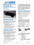
1
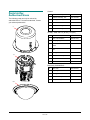
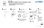
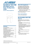
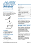
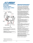
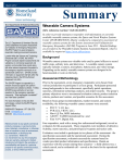
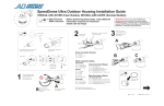
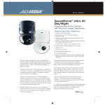
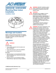
SpeedDome®
Optima LT Indoor
Camera Dome
Contents
Warnings ............................................................2
Before You Begin ...............................................3
Installation ..........................................................6
Troubleshooting .................................................9
Parts List for Authorized Users ........................10
Specifications ...................................................12
Declarations .....................................................14
RASEL Series
Installation and Service Guide
Customer Support
If you need assistance, contact your sales
representative.
The SpeedDome Optima LT indoor camera dome
mounts either to a hard ceiling or to a 2x2 tile
ceiling using a mounting plate (instructions for the
plate are supplied separately).
!
CAUTION: Save the box and packing
materials. These materials are required
should you need to ship the dome to a
repair center.
Note: The dome accepts either cable or conduit. If
running cable through a plenum ceiling, either
plenum-rated cable or flexible conduit is required.
© Sensormatic 2003
SPEEDDOME OPTIMA LT INDOOR CAMERA DOME INSTALLATION AND SERVICE GUIDE (8200-0181-01, REV. C)
1 of 14
EU power requirements: This product runs on
24Vac. In the EU, it is intended to be powered from
a Limited Power Source. A limited power source is
a certified source of SELV, and if inherently limited,
with 8 amps maximum output current, and a
maximum of 100VA available; or if not inherently
limited, fused with a maximum value of 3.3 Amps,
meeting section 2.11 of IEC950, and a maximum of
250VA available. The power supply can be
obtained through Sensormatic or through another
source where the provider can furnish the
verification. This is required to assure electrical
safety in the product.
Warnings
Please review the following warnings before you
install or service the camera dome.
ALWAYS USE:
· Proper safety equipment for the location and
type of installation.
· Proper lift equipment to reach the installation.
· Safety features of the lift equipment.
BE SURE:
Stromanforderungen in der EU: Dieses Produkt
wird mit 24 V Wechselstrom betrieben. In der EU
ist es für den Betrieb durch eine begrenzte
Stromquelle vorgesehen. Eine begrenzte
Stromquelle ist eine zertifizierte SELV-Quelle
(Schutzkleinspannung), bei inhärenter Begrenzung
mit einem maximalen Ausgangsstrom von 8 A und
100 VA maximaler Verfügbarkeit, bei nicht
inhärenter Begrenzung mit einer maximalen
Sicherung von 3,3 A gemäß Abschnitt 2.11 der
IEC950 und 250 VA maximaler Verfügbarkeit. Das
Netzteil kann über Sensormatic oder eine andere
Quelle bezogen werden, wobei der Anbieter den
Nachweis der Konformität bereitstellen sollte. Dies
ist zur Gewährleistung der elektrischen Sicherheit
des Produktes erforderlich.
· Electrical power is not connected to the dome
when connecting wires. Camera will move when
power is applied.
· Electrical power is not connected to nearby
fixtures that you might touch during installation.
DO NOT install this dome in hazardous areas
where highly combustible or explosive products are
stored or used.
This dome runs on 24Vac. DO NOT connect line
voltage to this dome.
North America power requirements: In North
America, this device is intended to be supplied
from a Class 2 power supply.
This installation should be made by a qualified
service person and should conform to all local
codes.
SPEEDDOME OPTIMA LT INDOOR CAMERA DOME INSTALLATION AND SERVICE GUIDE (8200-0181-01, REV. C)
2 of 14
Data cable requirements
Before You Begin
SensorNet
Manchester
Cable type
1
unshielded,
twisted
pair*
1
shielded
twisted
pair**
· Have electrical work comply with latest national
electrical code, national fire code, and all
applicable local codes and ordinances.
Wire gauge
22 AWG
18 AWG
Connection
Nonpolarized
Polarized
· Coordinate work with other trades to avoid
interference.
Max.
devices per
cable run
32
3
To ensure a smooth and successful installation,
observe the following requirements.
General Requirements
· Verify existing site conditions and coordinate
with the owner’s representative and appropriate
utilities as required.
* Power, data, and video cables can be ordered
separately or within a composite cable that can be
ordered in various lengths. Plenum-rated cables must
be used in indoor ceilings used for environmental air
return (called "other air space" in the National
Electrical Code). Order parts through your distribution
network.
· Obtain copies of all related plans, specifications,
shop drawings and addenda to schedule and
coordinate related work.
· Thoroughly review the project to ensure that all
work meets or exceeds the above requirements.
Bring alleged discrepancies to the attention of
the CCTV Project Coordinator.
Note: If you order cable from an outside source, wire
colors may be different.
** Belden 88760 (plenum), or Belden 8760 cable (nonplenum) cable is recommended. Plenum-rated cables
must be used in indoor ceilings used for environmental
air return (called "other air space" in the National
Mounting Requirements
Mounting space: Ensure there is the following
space above the ceiling to accommodate the
dome.
Electrical Code). Order cable directly from
Belden by calling 1-800-235-3361.
Plenum ceilings: Cable must be rated for plenum
or routed through flexible conduit. A cover plate for
the dome accepts ½" conduit.
Height above ceiling: 170mm (6.7in)
Diameter: 192mm (7.5in)
Structural members: Verify that ceiling members
can support the camera dome and mounting
structure, if used.
!
Weight: 2.5kg (5.5 lbs)
WARNING! Do not run cables adjacent
to or in the same conduit as line voltage
mains power.
Power cables. Make power cable lengths as short
as possible to minimize the affects of low line
voltages and outdoor cold temperature performance. Maximum cable length between a Class 2
LPS (low voltage) ac source, such as a J-box, and
the dome depends on the ac line voltage. See the
tables below for maximum cable lengths based on
the worst-case low line voltages.
Cable Requirements
Data cables: The following table shows cable
requirements for SensorNet and Manchester
networks. For more information about
communication protocols and cable networks, see
Communication Protocols and Cable Networks,
8000-2573-19.
The line voltage must not go below the voltage
shown for the dome to be able to power up and
operate at the corresponding distances shown.
Typically cable distances are used that provide a
15% margin between nominal and low line
conditions. For example, if the nominal voltage
measures 120Vac, restrict the cable length to the
distance for .85 x 120 or approximately 100Vac.
SPEEDDOME OPTIMA LT INDOOR CAMERA DOME INSTALLATION AND SERVICE GUIDE (8200-0181-01, REV. C)
3 of 14
Power cable requirements—Indoor Dome
The following table shows the maximum cable
distance for several worst-case low line voltages
between various indoor power sources and the
indoor SpeedDome Optima. These distances are
for Sensormatic composite cables, which use 18
AWG ac power wires.
This table applies to domes produced after October
of 2001; distances are much less for earlier domes.
Twisted Pair Adapter
The ADACTP01BNC Twisted Pair Adapter
(supplied) can be used to transmit video or video
with up-the-coax (UTC) dome control signals over
unshielded twisted pair (UTP) cables, point-topoint, up to 300m (1000ft).
The adapter mounts directly to the video source or
receiver without additional cabling and uses
Category 2-6 twisted pair wires to transmit the
video and dome control signals. The adapter does
not require power.
One adapter is supplied. If used, another adapter
must be ordered to for the connection at the other
end of the cable. The figure below shows twisted
pair cable connections. See installation guide
8200-0298-01 for details.
Indoor Dome
Worst-Case
Meters
AC Power Source
Low Line V
(Feet)
28 VA
117
130 (425)
Transformer
100
80 (250)
5604-0006-01
90
60 (200)
50 VA
117
160 (525)
Transformer
100
100 (325)
5604-0044-01
90
60 (200)
1-position SensorNet
117
160 (525)
RJ1SNUD
100
100 (325)
90
80 (250)
1-position SensorNet
240
160 (525)
RJ1SNUD-1
200
100 (325)
180
80 (250)
117
210 (675)
6-position SensorNet
100
130 (425)
Indoor J-Box
90
80 (250)
RJ6SN
240
210 (675)
200
130 (425)
180
80 (250)
Universal Transformer
117
130 (425)
0300-0914-01
100
100 (325)
90
60 (200)
Universal Transformer
240
160 (525)
0300-0914-03
200
100 (325)
180
80 (250)
Twisted Pair Adapter
(Dome End)
American Dynamics
Dome Or
Fixed Camera
Twisted Pair Adapter
(Fixed Camera End)
Cat 2-6 UTP Cable
Twisted Pair Adapter
(Switcher/Controller End)
Video Switcher/
Controller
SPEEDDOME OPTIMA LT INDOOR CAMERA DOME INSTALLATION AND SERVICE GUIDE (8200-0181-01, REV. C)
4 of 14
SensorNet/Manchester Line Termination
Power-Up Routine
SensorNet and Manchester communication
protocols require that the dome furthest from the
video controller or junction box be terminated.
Looking through the hole in the top of the dome,
ensure switch S1 is set to “terminated” for the
dome furthest from the video controller or junction
box. All other domes should be “un-terminated”.
After power is connected to the dome, the dome
performs a homing routine. During the homing
process, the camera will pan and then either:
· Go to the start point of the “apple peel” pattern,
or
· If powered up once before, to the last position in
memory.
Setting the Camera Address
Once the camera stops, the camera is online and
is ready to be controlled.
Accessed through the hole in the top of the dome
are rotary switches SW1, SW2, and SW3. The
address range for SensorNet is 001 to 255. The
address range for Manchester is 0 to 64.
Synchronizing Domes
To prevent picture rolling when switching from
camera to camera, all domes can be synchronized
to the ac source. A V-phase adjustment at the
control console enables the dome to sync to any
line phase.
For example, for address 107, set SW3 to 1, SW2
to 0 (black dot), and SW1 to 7.
Compatibility with the VM96 Controller
Save Packaging Material
If using a VM96 controller, the controller must be
Version 5.2 or higher.
Should the camera dome need to be sent to a
repair center, use the packaging that the dome was
shipped in.
Box for
Bubble
Plastic Bag
SPEEDDOME OPTIMA LT INDOOR CAMERA DOME INSTALLATION AND SERVICE GUIDE (8200-0181-01, REV. C)
5 of 14
3. To expose connectors and settings at the top
of the dome, remove the cover plate by
removing one screw and loosening the other.
Installation
24Vac (P10)
Parts required
Note: For installation to a tile ceiling, also order the
UL-approved RH2x2 Metal Plate Mounting Kit.
x100
x10
x1
1
7
Comm. (P9)
1 - No Polarity
2 - No Polarity
1 - WHT
Manch.
2 - BLK
SNet
AC
1
1
3.6m (12ft)
1
1
Set the camera address.
As an example, address
107 is shown.
SW3 SW2 SW1
Install Kit 0352-0020-01
Connector, 3-position (power)
Connector, 2-position (data)
Wire, hanging
Card, quick connect
Template, cutout, hard mount
Address Switches
AC
2109-0254-02
2109-0756-01
2898-0007-01
2402-2055-02
2402-2054-01
1
S2
Off
On
Procedure
7
6
5
4
3
2
Un-Terminated
S1
Comm. Select (S2)
8
P9
1
1
Video
Line
Termination
Switch
(S1)
Terminated
SensorNet / Manchester – Switch 6 & 7 "On", all others "Off"
Use the following steps when attaching the dome
to a hard ceiling.
4. Set address switches SW1, SW2, and SW3 for
the address (for example: 001–016 for VM16,
001–096 for VM96).
1. Using template supplied, cut a hole in the
ceiling. Run power and data cables and the
video cable to the hole.
5. If daisy-chaining domes, the dome furthest
from the video controller requires that termination switch S1 remain in the “terminated”
position (resistor symbol). All other domes
along the chain must be set to “un-terminated”.
6. Inside the opening, check communications
DIP switch S2 for the correct settings. For
SensorNet and Manchester, ensure switches 6
and 7 are “On”. Other switches should be “Off”.
7. Determine if conduit or cables will be used. If
using conduit, remove the Romex clamp and
use 1/2in. flexible conduit and appropriate
fittings. If using cables, they must be plenumrated if running through a ceiling plenum and
they must be secured using the cover plate
and Romex clamp.
2. For ease of installation, adjust the two “swing
out” mounting clips for ceiling thickness.
8. Leaving .6m (2ft) of service loop so the dome
can be dropped from the ceiling for servicing,
run the cable through the cover plate and
Romex clamp, if used.
Mounting Clip
9. Remove 2.5-3.8cm (1–1.5in) of jacket from the
cable end and install power and data
connectors supplied.
10. Plug connectors to the board according to the
figure above.
11. If using conduit, attach it to the cover plate
using the appropriate fittings and then reattach
the cover plate. If using cable, reattach the
cover plate to the dome using two screws and
then tighten the Romex clamp against the
cable (required to maintain the Plenum rating).
SPEEDDOME OPTIMA LT INDOOR CAMERA DOME INSTALLATION AND SERVICE GUIDE (8200-0181-01, REV. C)
6 of 14
15. Using safety wire, attach the dome to a strong
structural ceiling member as follows:
12. Attach a BNC connector to the video cable (if
not using the Twisted Pair Adapter). Also
attach the orange 3-pin power plug to
connector P10 and the gray 2-pin data
communications plug to connector P9. Wire
colors in diagram refer to cables supplied by
Sensormatic.
Note: Use a small screwdriver to tighten the
connector screws. DO NOT over tighten the
connectors!
a. Find a strong structural member capable of
supporting the dome. Wrap one end of the
wire around this member and twist the wire
around itself four times to secure.
b. Run the other end of the wire through one
of the holes above the swing out tabs.
Twist the wire around itself four times to
secure.
13. Plug video (or Twisted Pair Adapter), power,
and data communications cables into their
mating connectors in the top of the dome
housing.
!
c.
Ensure the wire is taut!
!
WARNING! Ensure power is off at
the source when connecting cables.
Otherwise, the dome will operate
during installation.
WARNING! Keep the wire as
taut as possible. Do not secure
to any component of a fire
control system.
14. Reattach the cover plate to the dome housing.
SPEEDDOME OPTIMA LT INDOOR CAMERA DOME INSTALLATION AND SERVICE GUIDE (8200-0181-01, REV. C)
7 of 14
19. Once the homing routine completes, affix the
bubble to the dome as follows:
16. Insert the dome into the hole in the ceiling.
a. Place the large hole at the end of the
lanyard over the screw head of the bubble
and pull its end to snap it in place. Loop
the lanyard to the inside of the housing.
17. Turn each of the two locking screws clockwise
to fully extend the “swing out” mounting clips
and to seat them tightly against the top surface
of the ceiling.
b. Center the bubble over the dome housing
and align its tabs with the mating tabs in
the housing.
18. Apply power to dome.
Note: When power is applied, the dome
checks its function by performing a homing
routine during which the camera pans and then
either goes to the start point of the “apple peel”
pattern or if powered up once before, to the
last position in memory. Once the camera
stops, the camera is online and is ready to be
controlled.
c.
Turn the bubble clockwise until it catches
the tabs and stops.
Also, green, red, and yellow LEDs will light in
various patterns to indicate status. Typically,
you do not need to view these LEDs unless a
failure occurs during or after the routine. See
“Troubleshooting” for an explanation of the
LED patterns.
SPEEDDOME OPTIMA LT INDOOR CAMERA DOME INSTALLATION AND SERVICE GUIDE (8200-0181-01, REV. C)
8 of 14
Pan control absent or improper, but other
control OK.
Troubleshooting
If a failure cannot be easily fixed, send the dome to
a repair center.
Send the dome to a repair center.
No power (no LEDs light).
Tilt control absent or improper, but other
control OK.
Check for power coming in from J-box or controller.
1. Check tilt belt operation. Fix the belt if
necessary.
Homing routine does not complete.
Green, red, and yellow LEDs are visible through
small holes in the dome housing that surround the
camera yoke. After power up, the LEDs light as
follows:
GREEN
(DS1)
RED
(DS2)
YELLOW
(DS3)
PLD Loading
(approx. 20 sec)
On
Off
Off
Homing Process
Off
Blink
On
Looking for Network*
On
Off
On
Online Waiting for 1st
Command**
Blink
Blink
On
2. If the problem cannot be corrected, send the
dome to a repair center.
Zoom, focus, and iris control is absent.
Check the flex cable connecting the camera the
housing. If you see damage, send the dome to a
repair center.
Only some camera control (for example, zoom
and focus works, iris doesn’t).
Send the dome to a repair center.
* If the dome remains in this state, it cannot locate either the
SensorNet, RS422, or Manchester network.
** The yellow LED remains on until it receives a PTZ movement
command, then goes off. Further PTZ commands will cause
the LED to blink; otherwise, the LED is off.
No video.
1. Check the video cable and its connection to
the dome. If not OK, fix or replace the cable.
2. Check the iris setting. Open iris or set to auto
iris.
3. If the problem cannot be corrected, send the
dome to a repair center.
Video rolls when switching cameras.
Perform V-phase adjustment at the controller.
Contrast or color off.
1. Check the iris setting. Open iris or set to auto
iris.
2. If the problem cannot be corrected, send the
dome to a repair center.
SPEEDDOME OPTIMA LT INDOOR CAMERA DOME INSTALLATION AND SERVICE GUIDE (8200-0181-01, REV. C)
9 of 14
General
Parts List for
Authorized Users
The following parts can only be ordered by
authorized users. To become authorized, contact
your sales representative.
3
1
Chassis Assembly, NTSC
0101-0013-01
2
Chassis Assembly, PAL
0101-0013-02
3
Housing Assembly
0404-0009-01
4
Install Kit
0352-0020-01
5
Bubble Assembly, Clear
0100-2458-01
6
Bubble Assembly, Smoked
0100-2458-02
Tilt Assy. 0400-1207-01 (NTSC), -02 (PAL)
1,2
7
Base, Tilt
0500-9110-01
8
Gear, Camera Base
0500-9112-01
9
Tilt Upright (2)
0500-9168-01
10
Camera, Hitachi VK-S144,
NTSC
2003-0037-11
11
Camera, Hitachi VK-S144,
PAL
2003-0037-12
12
Timing Belt
2500-0041-01
13
Tilt Motor with Pully
3501-0024-01
14
PCB, Tilt Sensor
0301-1524-01
15
Ribbon Cable, 20mm, Blk
6007-0039-03
Base Assy. 0404-0008-01
16
Base, Pan
0500-9109-01
17
Slip Ring
2100-0006-02
18
Bearing, Pan
2510-0040-01
19
Pan Motor Assy.
0400-1240-01
20
PCB, Dome System
0301-1620-01
5,6
SPEEDDOME OPTIMA LT INDOOR CAMERA DOME INSTALLATION AND SERVICE GUIDE (8200-0181-01, REV. C)
10 of 14
8
12
9
10,11
15
14
Tilt Assy. 0400-1207-01/-02
13
7
18
17
Base Assy. 0404-0008-01
16
19
20
SPEEDDOME OPTIMA LT INDOOR CAMERA DOME INSTALLATION AND SERVICE GUIDE (8200-0181-01, REV. C)
11 of 14
Specifications
White balance......................... Through the Lens (TTL)
Automatic Tracing White
Balance (ATW)
Operation
NTSC version:
Pickup device .................. 768 (H) x 494 (V) pixels
Manual pan speed.................. 1–50° per second
Target pan speed................... 100° per second max.
Scanning ......................... 525 lines, 60 fields,
30 frames
Pan travel............................... 360° continuous, no end
stop
Horizontal ........................ 15.734kHz
Vertical ............................ 59.9Hz
Manual tilt speed.................... 1–50° per second.
PAL version:
Target tilt speed ..................... 50° per second max.
Pickup device .................. 752 (H) x 582 (V) pixels
Tilt travel ................................ >90°
Optical zoom .......................... 22X
Scanning ......................... 625 lines, 50 fields,
25 frames
Digital zoom ........................... 11X
Horizontal ........................ 15.625kHz
Bubble density ....................... Clear, f0
Vertical ............................ 50Hz
Tilt/Pan accuracy.................... ±0.5°
Lens
Zoom/Focus accuracy............ ±0.5%
Quick View™ access ............. < 2 seconds to pan and tilt
position
Design .................................... Aspherical
Focal length............................ 4 to 88mm
< 3 seconds to full zoom
position
Aperture.................................. f1.6 (wide), f3.8 (tele)
Scanning area ........................ 3.2mm (H) x 2.4mm(V)
< 1 second focus on
VM16 and VideoManager
controllers
Viewing angle:
4 mm ............................... 47.0°H x 35.2°V
< 7 seconds focus on
VM96 and RV2715
controllers.
88 mm ............................. 2.2°H x 1.65°V
Field-of-View Formulas:
Synchronization ..................... Automatically selected
Field-of-View Formulas:
Line locked...................... Remote V-phase
adjustment
Internal............................ Built-in sync generator
Program storage .................... 256K bytes of electrically
programmable Flash
Memory
3.2 mm* x distance from camera (m)
Focal length (mm)
= Horizontal view (m)
2.4 mm** x distance from camera (m)
Focal length (mm)
= Vertical view (m)
* Horizontal scanning area of pickup device (mm) in camera.
** Vertical scanning area of pickup device (mm) in camera.
Data storage .......................... 128kB of SRAM
Video output connector .......... Female BNC
Example: Wide angle view with lens at 6mm and viewed
object at 10m.
Product life ............................. 5 years operation
500,000 position changes
3.2mm x 10m
Color Camera Specifications
6mm
2.4mm x 10m
Type ....................................... Interline Transfer ¼" CCD
array
6mm
= 5.33m Horizontal view (m)
= 4.0m Vertical view (m)
Scanning system.................... 2:1 interlace
Horizontal resolution .............. > 450 lines at center
Video out................................ 1.0 Vp-p / 75 ohms
composite
Signal/Noise........................... 50dB (typical)
Minimum illumination.............. 1.0 lux (20 IRE)
Gain control............................ Automatic (AGC)
SPEEDDOME OPTIMA LT INDOOR CAMERA DOME INSTALLATION AND SERVICE GUIDE (8200-0181-01, REV. C)
12 of 14
Electrical Specifications
SensorNet Communications
Power Line
Address range ........................ 0 to 255
Input voltage .......................... 18–30Vac, Class 2
Limited Power Source
Bit rate: ................................... 230.4Kbps
Design tolerance .................... 16–36Vac
Maximum loads ...................... 32 per node
Line frequency ....................... 50/60Hz
Node repeaters....................... SensorNet junction boxes
Power consumption................ 21W max.
Cable topologies..................... Daisy chain
Backbone
Star
Network distance .................... 1km
Power on inrush current ......... 3A
Allowable drop out:................. 33ms
Transmission medium ............ Single non-polarized
unshielded twisted pair
UTP 22AWG
Connector: ............................. Plug-in Euro-style terminal
block 5.08mm
Max. cable distance ............... See chart on page 4.
Wire configuration................... Single unshielded twisted
pair UTP 22AWG nonpolarized
Surge Protection
Video output........................... Gas discharge tube rated
at:
· 8/20µs impulse
discharge current: 10kA
· Ten 8/20µs impulses
discharge current: 5kA
3.9 ohm series resistors
Low capacitance Zener
suppressor 6.5V 1500W
Connector:.............................. Plug-in Euro-style terminal
block 5.08mm
Power line .............................. Gas discharge tube
impulse rated at:
· 8/20µs impulse
discharge current: 10kA
· Ten 8/20µs impulses
discharge current: 5kA
TVS rated at 60V, 250A,
1.5 Joules, 8/20µs
impulse
Network distance .................... 1.5km
Terminating resistor ............... 120 ohms, switch
selectable
Manchester Communications
Address range ........................ 1 to 64
Bit rate .................................... 31Kbps
Maximum loads ...................... 32 per node
Node repeaters....................... SensorNet junction boxes
Cable topology........................ Daisy chain
Transmission medium ............ Single polarized twisted
pair 18AWG (Beldon
8760)
Connector............................... Plug-in Euro-style terminal
block 5.08mm
SensorNet/Manchester .......... Gas discharge tube
impulse rated at:
· 8/20µs impulse
discharge current: 10kA
· Ten 8/20µs impulses
discharge current: 5kA
Isolation transformer
coupled, 2000Vrms
PTC resettable fuse
protects transformer
TVS rated at 5.6V, 40A,
0.1 Joules, 8/20µs
impulse
Terminating resistor ............... 120 ohms, switch
selectable
SPEEDDOME OPTIMA LT INDOOR CAMERA DOME INSTALLATION AND SERVICE GUIDE (8200-0181-01, REV. C)
13 of 14
Mechanical Specifications
Other Declarations
Camera Dome
Thank you for using American Dynamics products. We
support our products through an extensive and worldwide
network of dealers. The dealer, through whom you originally
purchased this product, is your point of contact if you have a
need for service or support. Our dealers are fully empowered
to provide the very best in customer service and support.
Dealers should contact American Dynamics at
(800) 507-6268 or (561) 912-6259 or on the web at
www.americandynamics.net.
Housing diameter................... 190mm (7.5in)
Housing height
(above ceiling)........................ 210mm (8.26in)
Bubble diameter..................... 178mm (7.0in)
Bubble depth
(below ceiling) ........................ 94mm (3.7in)
Weight.................................... 2.5kg (5.5 lbs)
WARRANTY DISCLAIMER: Sensormatic Electronics
Corporation makes no representation or warranty with respect
to the contents hereof and specifically disclaims any implied
warranties of merchantability or fitness for any particular
purpose.
Environmental Specifications
Operating temperature:
NOTICE: The information in this manual was current when
published. The manufacturer reserves the right to revise and
improve its products. All specifications are therefore subject to
change without notice.
Indoor..................................... –10°C to 50°C
(14°F to 122°F)
Humidity ................................. 0–95% non-condensing
LIMITED RIGHTS NOTICE: For units of the Department
of Defense, all documentation and manuals were developed at
private expense and no part of it was developed using
Government Funds. The restrictions governing the use and
disclosure of technical data marked with this legend are set
forth in the definition of “limited rights” in paragraph (a) (15)
of the clause of DFARS 252.227.7013. Unpublished - rights
reserved under the Copyright Laws of the United States.
Storage temperature .............. –20°C to 65°C
(–4°F to 149°F)
Declarations
Regulatory Compliance
TRADEMARK NOTICE: American Dynamics and
Sensormatic are trademarks or registered trademarks of
Sensormatic Electronics Corporation. Other product names
mentioned herein may be trademarks or registered trademarks
of Sensormatic or other companies.
REG ID................................... SV SDUW
Emissions............................... 47 CFR, Part 15
EN 50130-4
ICES-003
EN 55022
Safety..................................... UL1950
CSA C22.2 No 950
EN 60 950
COPYRIGHT: Under copyright laws, the contents of this
manual may not be copied, photocopied, reproduced,
translated or reduced to any electronic medium or machinereadable form, in whole or in part, without prior written
consent of Sensormatic Electronics.
MDR 9/03
FCC COMPLIANCE: This equipment complies with Part 15
of the FCC rules for intentional radiators and Class A digital
devices when installed and used in accordance with the
instruction manual. Following these rules provides reasonable
protection against harmful interference from equipment
operated in a commercial area. This equipment should not be
installed in a residential area as it can radiate radio frequency
energy that could interfere with radio communications, a
situation the user would have to fix at their own expense.
EQUIPMENT MODIFICATION CAUTION: Equipment
changes or modifications not expressly approved by
Sensormatic Electronics Corporation, the party responsible for
FCC compliance, could void the user's authority to operate the
equipment and could create a hazardous condition.
SPEEDDOME OPTIMA LT INDOOR CAMERA DOME INSTALLATION AND SERVICE GUIDE (8200-0181-01, REV. C)
14 of 14