1
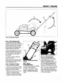
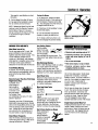
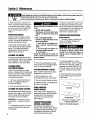
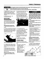
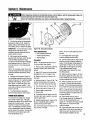
®
Operator's Manual
3-1n-1 Mower
Model SRA 621
/
IMPORTANT:READ
SAFETY RULES AND INSTRUCTIONS
CAREFULLY
Warning: This unit is equipped with an internal combustion engine and should not be used on or near any unimproved forest-covered, brushcovered or grass-covered land unless the engine's exhaust system is equipped with a spark arrester meeting applicable local or state laws (if any).
If a spark attester is used, it should be maintained in effective working order by the operator. In the State of California the above is required by law
(Section 4442 of the California Public Resources Code). Other states may have similar laws. Federal laws apply on federal lands. A spark arrester
for the muffler is available by contacting the service department at Cub Cadet LLC, P.O. Box 361131 Cleveland, Ohio 44136-0019.
CUB CADET
PRINTED
IN USA
LLC, P.O. BOX 361131,
CLEVELAND,
OH 44136-0019
FORM
NO. 769-00052A
(02/2002)
TABLEOF CONTENTS
Content
Page
Calling Customer Support ....................................................
2
Safety ...................................................................
3
Assembly .................................................................
6
Features and Controls .......................................................
8
Operation ................................................................
10
Maintenance ..............................................................
15
Parts List .................................................................
22
Warrany Information ........................................................
Back Cover
FINDINGMODELNUMBER
This Operator's Manual is an important part of your new Mower. It will help you assemble, prepare and maintain the
unit for best performance. Please read and understand what it says.
Before you start assembling your new equipment, please locate the model plate on the equipment and copy the information from it in the space provided below. This information is very important if you need help your Cub Cadet dealer.
You can locate the model number by looking at the rear surface of the cutting deck. A sample model plate is
explained below. For future reference, please copy the model number and the serial number of the equipment
in the space below
Copy Model Number Here
Copy Serial Number Here
C.UZ)
_--0,1_.,_}_,
www.cubcadet.com
CUB
CADET
LLC
P. O. BOX
361131
CLEVELAND, OH 44136
• DEALER LOCATOR PHONE NUMBER: 877-282-8684
ENGINEINFORMATION
The engine manufacturer is responsible for all engine-related issues with regards to performance, power-rating,
specifications, warranty and service. Please refer to the engine manufacturer's Owner's/Operator's Manual packed
separately with your unit for more information.
CALLING CUSTOMER SUPPORT
If you have difficulty assembling this product or have any questions regardingthe controls, operation or maintenance
of this unit, please call the Customer Dealer Referral Line.
number
and serial
number
readythe
when
you call.Dealer
See previous
to locate
this
information.
Call 1- (877)
282-8684
to reach
Customer
Referral section
Line. Please
have
your
unit'smodel
Safety_
This machine meets voluntary safety standard B71.1 1998, which is sponsored by the Outdoor Power
EquipmentInstitute, inc., and is publishedby the American
NationalStandardsInstitute.
Safety AlertSymbol
manualand
on the unitto
alertyou
to potential
This is a safetyalert
symbol.
It is used
in this
hazards. When you seethis symbol, read and
obeythe messagethat follows it. Failureto obey
safety messagescould result in personalinjury or property
damage.
d_lb
WARNING
The engine exhaust from this productcontains
chemicals knownto the State of California to cause
cancer, birth defects or other reproductive harm.
IMPORTANT
SateOperationPracticesforWalk-BehindMowers
Thiscuttingmachineis capableof amputatinghandsandfeet andthrowingobjects.
Failureto observethe followingsafetyinstructions
couldresultin seriousinjuryor death.
I. GENERALOPERATION
1. Read,understandand follow all
instructions on the machineand in
the manualsprovidedwith the unit.
Bethoroughly familiar with the
controls and the proper use of the
mower beforestarting.
2. Do net put hands or feet near or
under rotating parts. Keepclearof
the mower bladeand discharge
opening at all times.
3. Onlyallow responsibleindividuals,
who are familiar with the instructions, to operatethe mower.
4. Clearthe area of objectssuch as
rocks, toys, wire, bones, sticks, etc.,
which could be picked up and thrown
by the blade.
5. Be surethe areais clearof other
peoplebefore mowing. Stop mower if
anyoneenters the area. Keep
bystandersat least 25 feet awayfrom
the areaof operation.
6. Do not operatethe mower when
barefoot orwearing opensandals.
Alwayswear substantialfoot wear.
7. Do not pull mower backwardsunless
absolutelynecessary.Look down and
behind beforeand while moving
backwards.
B.
Donot operatemower without all
guardsin placeand either the entire
GrassCatcher,the Mulching Plug or
the Side-DischargeChuteinstalled.
ROTATINGBLADES-- Donot open
dischargeguard while engineis
running.
9. Referto providedinstructions
for
proper operationand accessory
installation. Useonly accessories
approvedbyGardenWay Inc.
10. Shut off enginewhen crossinggravel
drives, walks, or roads.
11. Stop engineanddisconnectspark
plug wirefrom sparkplug whenever
you leaveunit, beforecleaningmower
or uncloggingchute.
12. Shut the engineoff and wait until the
blade comesto a completestep
before installing or removingthe
Mulching Plug,Side-DischargeChute
or the GrassCatcher. Makecertain
that an attachmentis installed before
operatingthe mower.Emptythe
Grass Catcherafter eachusedecomposingdebris could generate
enough heatto catchfire.
13. Mow only in daylight or in good artificial light.
14. Do not operatemewer while under
the influence of alcohol or drugs.
15. Neveroperatemower in wet grass.
Alwaysbe sure of your footing; keep
a firm hold on the handleand walk;
neverrun.
16. Be sure WheelDrive Bail isdisengagedbefore starting engine.
17. If the unit shouldstart to vibrate
abnormally,stop the engineand disconnectthe spark plug wire. Then
check immediatelyfor the cause.
Vibrationis generallya warning of
trouble.
18. We recommendthat you wearsafety
gogglesor safetyglasseswhen
operatingthe mower.
19. Watchfor traffic when operating
near,or whencrossing roadways.
20. Neverattempt to carry childrenor
otherpassengersonthe mower.
They couldfall off and be seriously
injured,or they could interferewith
the safeoperationof the mower.
21. Checkthe operationefthe Operator
PresenceControl Bail (tep bail,
mountedon handlebar)beforeeach
use.TheOperatorPresenceControl
Bailis a safetydevicethat is designed
to stop the mower blade within three
secondsafter releasingthe bail. The
bail must operatefreely whenpulled
backagainstthe handlebarand
returnautomaticallyto the disengagedposition when released.If the
engine runs longer thanthree
secondsafter releasingthe bail,the
system is not working properly.
Immediatelycontactan authorized
servicedealeror the Factory
TechnicalServiceDepartmentfor
instructions.Donot usethe mower
until the mechanismis repaired.
22. Neverrun the engine in an enclosed
area.Engineexhaustcontainscarbon
monoxide,a deadlygasthat is
odorless,colorlessand tasteless.
Alwaysrun the engineoutdoors and
makesure there is adequate
ventilation.
3
Section1: Safety
II. OPERATINGONA SLOPE
Slopesare a majorfactorrelatedto slip
andfall accidentswhichcan resultin
severeinjury. All slopesrequireextra
caution.If youfeel uneasyon a slope,
do notmowit.
DO:
Mow acrossthe face of slopes;never
up and down, Exerciseextreme
cautionwhen changingdirection on
slopes.Avoid slopes greaterthan 15°.
Neverallow childrento operatethe
mower.
4,
5. Use extracarewhenapproaching
blind corners,shrubs, trees,or other
objectsthat may obscurevision.
1. Useextra carein handlinggasoline
and otherfuels.They are flammable
and their vapors are explosive.
a) Use only an approvedcontainer.
b) Neverremovegascapor add fuel
whenthe engineis running.
Allow engineto cool before
refueling. Donot smoke.
Watchfor holes,ruts, or bumps.Tall
grass can hide obstacles.
c) Neverrefuelthe machine
indoors.
DONOT:
d) Neverstorethe machineor fuel
containerinsidewherethere is an
openflame, such as a water
heater,etc.
Do notmowneardrop-offs,ditches,
or embankments.
Theoperatorcould
loosefooting or balance.
Do not mow excessively
steepslopes.
On notmow on wet grass.Reduced
footing could cause slipping.
,
III. CHILDREN
2, Bealertandturnmower off if
childrenenterthearea.
3. Beforeand while moving backwards,
look behindand downfor small
children.
8.
IV. SERVICE
Removeobjectssuch as rocks, tree
limbs, etc.
Tragicaccidentscan occuril the
operatoris not alert to the presenceof
children.Childrenare oftenattractedto
the mowerandto the mowingactivity.
Neverassumethat childrenwill remain
whereyoulast sawthem.
1, Keepchildren out ofthe mowing area
and underthe watchful careof a
responsibleadult.
After striking an object, stop the
engineand disconnectthe sparkplug
wire. Inspectthe mower and repair, if
necessary,beforerestarting.
7,
3.
4,
5,
e) Movemower awayfrom any
gasolinefumesbeforestarting
the engine.
Neverrun an engineinside u closed
area.
Nevermakeadjustmentsor repairs
with the enginerunning. Disconnect
the spark plug wire and move the
wire away from the plug to prevent
accidentalstarting.
Keepall nuts and screws,especially
the bladeattachmentbolts, tight and
keepequipmentin good condition.
Nevertamper with safetydevices.
Checktheir operationregularly.
6. Keepmower free of grass,leavesor
otherdebrisbuild-up.Cleanup oilor
fuel spillage.Allow mower to cool
beforestoring.
.
Neverattempt to make mower cutting
heightadjustmentswhile the engine
is running.
Grasscatchercomponentsare
subjectto wear, damageand deterioration, which could exposemoving
partsor allow objectsto be thrown.
Frequentlycheckcomponentsand
replacewith factory recommended
parts,when necessary.
10. The mower blade is sharp andcan
cut.Wrap the bladeor weargloves,
and useextracautionwhenservicing.
11. Do not changetheenginegovernor
setting or overspeed
the engine.
12. Do not touch engineparts which may
behot from operation.Allow parts to
cool completelybefore inspecting,
cleaningor repairingthe mower.
13. Maintain or replacesafetyand
instructional decals. Referto the
Parts List for replacementdecal
information.
Section1: Safety
SAFETY DECALS
Foryour safetyandthe safetyof others,varioussafetydecalsare locatedon your unit (below- size not to scale).
Keepthe decalscleanand legible at all times. Contactyour localservicedealeror the Factoryfor replacementsif anydecals are
damagedor missing. Referto the Parts List pagesin this Manualfor decalpart numbers.
DANGER
Locatedon the belt
cover. Thisdecal
providesa list of
warningstohelp avoid
seriousinjury.
Locatadonthedischargeoutletguard. Thisdecalwarns
notto operatethe mower withoutthe dischargeoutlet
guardin place andeitherthe GrassCatcher,Mulching
Plugor Side-DischargeChuteInstalled. Thisdecalalso ,
warnsthatthereare rotatingblades. Donot openthe
dischargeoutletguardwhile the engineis running.
Locatedon the left side of the
mowardeck. Thisdecalcautions
to keephandsaway.
Assembly
A
Before operating your machine,
carefully read and understand all
safety, controlsand operating instructions in this Manual, the separate
Engine Owner's Manual, and on the
decalson the machine.
Figure2-2"Attachments
Failure to follow these instructionscan
resultin seriouspersonalinjury.
ASSEMBLINGNEWUNITS
B
INTRODUCTION
ThisSectioncovers unboxingand assem- The mowerbladeis sharpand cancause
bling your new mower. Pleasecarefully
serious personalinjury, when working
readall the instructionsbeforeyou
near the mower blade, wear heavy
attempt to assemblethe mower. After
leather glovesto protestyourself from
you finish assemblingthe mower,read
the sharpedges.
Section1: Safety,Section3: Featuresand
Controls,and Section 4: Operation,before IMPORTANT:The mower is shipped
usingthe mower.
without motor oil inthe enginecrankcase.
Add motor oil to the enginebefore
INSPECTION
starting. Followinstructions
inthis
Inspectthe mower immediatelyafter
Section.
delivery. Makesure that neitherthe
carton nor the contents havebeen
Step 1: UnpackMower
damaged.
1. Themower comesfully assembled
with the handlebarsfoldedcompactly
for
If you find or suspect any damage,
shipment.Removethe mower fromthe
contact the carrier (trucking company)
shippingcontainer.
right away. Inform them of the specific
damageand that you wish to file a claim.
2. Thecontrolbails (P, Figure2-6) are
securedto the handlebar(Q) with a cable
To protectyour rights, be sureto putthis
tie. Cut the cabletie off and removethe
in writing to the carrier within 15 days
protective packing material,
after your machinearrives. Thecarrier
will let you know howto proceedwith
3. Follow steps2 through 8 to complete
your claim.
mowerassembly.
LOOSE PARTS
Thefollowingitemsare shippedloose
within the container.
NOTE:The mower is
shippedwith the
Mulching Plug
(B, Figure2-2)
installed in the
d schargeout et
(Figure2-1).
• The Grass
Catcherattachmenl
(A, Figure2-2).
• Side-DischargeChuteattachment
(C, Figure2-2).
5. Tightenbothlowerhandlebaradjustment knobssecurely.
6. Loosenthe two upper handlebar
adjustmentknobs (3, Figure2-5).
7. Unfoldthe upper handlebarassembly
(4, Figure2-5) and align with the lower
handlebarassembly. Be sure notto
pinch, kink, or over-stretchthe cables
while unfolding.
8, Tightenbothupper handlebaradjustment knobssecurely.
9. Checkthe starter rope,Make sure
that it doesnot catch underthe top
handlebaradjustment knob (I, Figure
2-6). Thestarter rope should stretch
unobstructedto the engine.
Figure2-3: Assemblinghandlebar. (Rightside handlebarstrutshown.)
Step 2: UnfoldHandlebarAssembly
1. Loosenthe two lowerhandlebar
adjustment knobs (1, Figure2-5),
2. Carefullyunfold lower section ofthe
handlebarassembly(2, Figure2-5).
Watchthe cableswhile unfoldingand
make surethat they do not pinch, kink, or
over-stretchwhile unfolding.
3. Tighten the two lower handlebar
adjustment knobsjust enoughto allow
the two handlebarstruts (H, Figure2-3)
to move in and out slightly.
4. Insert thetab (F, Figure2-3) on each
handlebarstrut into the slot (G) one each
side of thedeck. Becertainto routethe
cablesinsidethe left sidestrut as shown
in Figure2-4.
Figure2-4: Cablescorrectlyroutedinside
handlebarstrut.
Section2: Assembly
\\
\\
_
Figure2-5:Unfoldingthe handlebar,
Step3: Adjust HandlebarHeight
1. Loosenone of the lower handlebar
adjustmentknobs (K, Figure2-6) and give
the knob a tap inward to freethe square
shaft on the screw (N, Figure2-7) from
the keyedslot (0) in the handlebarstrut.
Repeatthis step for the other side.
2. Movethe handlebarstrut up or down
to align the squareshaft (N, Figure2-7)
with one of the three squarekeyedslots
(0). The middleslot is the medium
height setting.
Figure2-7" Adjustinghandlebarheight.
3. Tighten the handlebaradjustment
knobs very securely.
NOTE:Make surethat the squareshaft
seatssquarelyinto the slot beforetightening the adjustmentknobs.
Step4: Add Motor Oil to Engine
1. Movethe mower to a levelarea.
2. Add motor oil accordingto the specificationsand instructionsprovided in the
separateEngineOwner's Manual.
• Keepoil levelat the FULLmark on the
dipstick to avoid enginedamage.
Figure2-6: Fullyassembled
handlebar
assembly.
Step 5: Perform
Final AssemblyCheck
1. Checkall nuts, screws,and handlebar
adjustment knobsfor tightness.
2. Besure to readSection 1: Safety,
Section3: Featuresand Controlsand
Section4: Operationbeforeusing the
mower.
Step 6: Set Up Mowing Mode
Your mower can be set up for anyof
three mowing modes. Thesemowing
modes canbag clippings,mulch
clippings,or dischargeclippings out the
side. See Setting UpMowing Modes in
Section4 for detaileddescriptions
and
instructions onhow to set up eachmode.
NOTE:Themower is shippedin Mulching
Mode. This meansthat the Mulching
Plugis installedinto the dischargeoutlet
(Figure2-1) andthat the mower is ready
to mulch grassclippings.
• Changeoil according to scheduleand
instructions in EngineOwner'sManual.
7
FeaturesandControls
H
//
/
\\\
/
H
G
P
/
I
A: OperatorPresenceControlBail
G:GrassCatcher
R: WheelSpeedControl
C: WheelDriveRail
H:Discharge
OMletGuard
I: LowerHandlebar
Adjustment
Knob(2)
J:Handlebar
HeightAdjuster
(2)
K:CuttingHeigMAdjustment
Lever
L:BeltCover
D: RecoilRope Starter
E: UpperHandlebarAdjustmentKnob(2)
F: GrassGaugaTM
GrassFill Indicator
M: Side-DischargeChute
N: MulchingPlug
O:DischargeOutlet
P: ClutchCableAdjuster
Figure3-1
MOWERATTACHMENTS
Before operating your machine,
carefully read and understand all
safety, controlsand operating instructions in this Manual, the separate
Engine Owner's Manual and on the
decalsonthe machine.
Failure to follow these instructionscan
resultin seriouspersonalinjury.
INTRODUCTION
This Section introduces
the featuresand
controls found on the lawn mower.
Carefullyreview the information in this
Section,then read Section4, Operation
beforeusingthe mower.
8
The mower is suppliedwiththree easily
changedattachments--the Grass
Catcher(I, Figure3-1), Mulching Plug (N)
and Side-DischargeChute(M)-- which
providethree different mowing modes.
See Setting Up Mowing Modes in Section
4 for detailedinformation on howto
install and usethe attachments.
A uniquefeature,the CubCadetRapid
AttachTM System,is incorporatedintothe
design ofthe attachments. This system
enablesyou to quickly and easilyinstall
the attachmentswithout using tools.
GrassCatcher Attachment
Usethe CrassCatcher(G,Figure3-1) to
collectclippings for disposal. Thebag
can hold overtwo bushels of clippings.
The GrassCatcheris equippedwith the
CubCadet_ GrassGaugnTM
feature (F,
Figure3-1). The GrassGaugefeature is a
grassfill indicator that providesa visual
alertwhenthe bag is full. See Bagging
Mode in Section4 for detailedinformatien.
Side-DischargeChuteAttachment
Usethe Side-DischargeChute(M, Figure
3-1) to direct grass clippings outthe left
side (from operator's position) of the
mower. SeeSide-DischargeModein
Section4.
Section
3: Features
andControls
Mulching Plug Attachment
Usethe MulchingPlug(N, Figure3-1) to
mulch lawn clippings.See Mulching
Modein Section 4.
MOWER CONTROLS
Thefollowing informationidentifiesand
describesthe controls for all mower
models,
OperatorPresence ControlBail
The OperatorPresenceControl Bail
(A, Figure3-1) must be pulled back
againstthe handlebarand held there
while starting the engineand operating
the unit. Releasingthe bail will shut off
the engine and stop the mower blade.
The enginewill not restart unlessthe bail
is pulled backagainstthe handlebar.
NOTE:This control disengagesan engine
brakewhenpulled backagainstthe
handlebarand engagesthe enginebrake
when released. The mower blade is
bolteddirectly to the engineshaft,
therefore it stops whenthe enginestops.
The enginewill not restart unlessthe bail
is puffed backagainstthe handlebar. See
Stoppingthe EngineandMower Bladein
Section 4 for more information.
Wheel Drive Bail
The WheelDrive Bail(C, Figure3-1)
engagesthe poweredrear wheelswhen it
ispulledup againstthe handlebar,and
disengagesthe wheelswhen released.
See Mowing and Turningthe Mowerin
Section 4 for more information.
To movethe mower without engine
power,releasethe controlsand push or
pull the mower.
NOTE:The piniongearsinsidethe rear
wheels may producean occasional
knocking soundwhen pushing or pulling
the mower manually. This sound is
harmless. Do not lubricatethe drive
wheels.Servicethedriveassemblyonly
as instructedin Section5.
Wheel SpeedControl
Fuel Shut-OffValve
TheWheel SpeedControl (B,Figure3-1)
providesthree differentwheelspeeds.
Selectionsare:
TheFuelShut-OffValve(if so equipped)
opensandclosesthefuel line. Seethe
EngineOwner'sManualfor information
specifictoyourengine.
• 1 for low speed
• 2 for mediumspeed
• 3 for high speed
SeeMowing in Section4 for moreinformation.
CuffingHeight AdjustmentLever
Thiscontrol(K, Figure3-1) provides six
cutting heights,enablingyou to choose
the most appropriateheightfor the lawn
condition. Cuttingheights rangefrom
approximately1-1/4-inchesto 4 inches.
SeePreparationfor Mowing in Section4
for more information.
NOTE:Actualcuttingheight willvary
accordingto turf conditions.
Recoil RopeStart
The recoil rope start(D, Figure3-1) is
usedto pulFstartthe engine.Seethe
EngineOwner'sManualfor startinginformation specificto your engine.Also see
Starting the Enginein Section4.
AdjustableHandlebarHeight
The mower providesthree handlebar
height settings(J, Figure3-1). See Step
5: AdjustHandlebarHeight in Section 2.
ENGINECONTROLS
Throttle
Models SRA621 has anenginethat is
equippedwith a fixed throttle speedfor
the most efficientengineperformance
under varying loads.
PrimerBulb
The Primer Bulbis usedto start a cold
engine.Seethe EngineOwner'sManual
fur informationspecific to your engine.
Operation
TheGrassCatcherand the Side-Discharge
Chuteboth use the samesystem. This
tab (A,
Before operatingthe mower, carefully systemconsists of an elongated
read and understandall safety, control Figure4-1) on the top of the discharge
and operating instructions in this outlet anda receptacle(B) built into the
Manual, the separate Engine Owner's top of the GrassCatcherdoor and the
Manualand the decalson the machine. Side-DischargeChute.
Failure to follow these instructionscan
resultin seriouspersonalinjury.
Attachingthe Mulching Plug is just as
easy. Hold openthe dischargeoutlet
guard (K, Figure4-1) and insert the plug
(L), with the word "TOP" facing up, into
the dischargeoutlet.
TheGrassCatcheralsohasa
GrassGaugeTM
grass-fill indicator(Figure
4-3) which makesit easy to tell whenthe
bagis full. Theindicator isa rectangular
pieceof cloth sewnto the top of the bag.
Theindicator laysflat againstthe bag
whenthe bag is full (F, Figure4-3) and
billows (G) whenthe bag is not full.
NOTE:Windy conditions
may affect the
indicator'sability to providean accurate
bagfill reading.
SettingUpBaggingMode
1. With the engineand bladestopped,
removethe Mulching Plug or SideDischargeChute.
• Never operate the mower with the
discharge outlet guard removed or
proppedopen.
2. Graspthe GrassCatcherby the wireformed handle. With the other hand,hold
open the dischargeoutlet guard (C, Figure
4-2).
• Do not operate mower without the
GrassCatcher,MulchingPlugor SideDischargeChutein place.
• Never change mowing modes or
empty the Grass Catcher while the
engineis running.
• Check the condition of the Grass
Catcherfor excessivewear or deterioration. If damaged,contactan authorized dealer or the factory for a
replacement.
INTRODUCTION
SETTING UP MOWING MODES
Findanopen, levelareaand practice
usingthe mower controls. Onlyafter you
becomefamiliar with the mower should
you use it in smaller areasor on uneven
terrain.
Thelawn mower hasthree mowing
modes:bagging mode,mulching mode
and side-dischargemode. Thefollowing
providesdescriptions of the three modes
and how to implementthem.
CUB CADET ®
RAPID ATTACHTM SYSTEM
The RapidAttachSystem (Figure4-1) is a
feature designedinto the mower deck
which enablesyou to install andremove
the GrassCatcher,the Side-Discharge
Chuteand the MulchingPlug quicklyand
easily.
10
Figure4-1: CubCade_ RapidAttachTM
System.
Readthis Section thoroughly beforeyou
start the engine. Thentake the time to
familiarizeyourself with the mower's
basic operation.
BaggingMode
The mower is set up for bagging mode
whenthe GrassCatcheris attachedto the
dischargeoutlet.
TheGrassCatcheris equippedwith two
handlesand a swing-opendoor that
makesemptyingeasy. Usethe wireformed handleto help attach, remove,
transport andemptythe bag. Usethe
rear cloth handleto lift the bottom of the
bagwhen emptying.
Figure4-2: AttachingGrassCatcher.
3. Lower (at an angle)the bag door (D,
Figure4-2) onto the tab (E) on the
dischargeoutlet. Makesurethe bagdoor
seatssquarelyonto the tab and covers
the tab completely.
Removingthe GrassCatcher
1. Whenmowing,the GrassCatcheris
full whenthe grassfill indicator lays flat
againstthe bag (F, Figure4-3).
An alternativemethod for judging bag
fullnessis to nudgethe bag with your
foot. Thebag will give easilywhen not
full, and will resistwhenfull.
Section
4: Operation
[
• Checkthe OperatorPresenceControl
Bailfor freedom of movement.
• Checkthe WheelDriveControl Bailfor
freedom of movement.
• Checkbladefor excessive
wear or
damage. Do not operatethe mower
with a damagedblade.
•S_curelyconnectthesparkplugwire to
thesparkplug.
Figure4-3: GrassGaugeTM
indicaieswhenbag is full (F)and notfull (G).
4. Adjusthandlebarheight- Themower
hasthreehandlebarheightswhichcanbe
adjustedas follows:
a. Loosenoneofthe lower handlebar
adjustmentknobs (H, Figure4-5) and
givethe knob a tapto freethe
handlebarstrut (K) for adjustment.
Repeatfor the other side.
2. With the engineand bladestopped,
ho_dopenthe dischargeoutlet guard (C,
Figure4-2). With the other hand,grasp
the wire-formedhandleand guide the bag
up and off the dischargeoutlet.
Mulching Mode
The mulching mode cuts and recuts grass
clippings within the mower housing
beforerecyclingthe finely cut clippings
into the lawn. Mulching makesit easier
for the the lawn to absorbthe grass
nutrientsback into the soil,
SettingUp MulchingMode
1. With the engineand bladestopped,
removethe GrassCatcheror the SideDischargeattachment.
2. Lift open tho dischargeoutlet guard
(K, Figure4-1).
3. Position the plugwith the word "TOP"
facing up and pushthe Mulching Plug
firmly into the discharge outlet (Figure
4-4).
4. The plug's flange (rim) mustfit snugly
againstthe edgeof the dischargeoutlet to
ensureefficient mulching (Figure4-4).
2. Graspthe Mulching Plug's hand-grip
with one hand and pull backuntil the plug
clearsthe dischargeoutlet.
Side-Discharge Mode
Use the Side-DischargeChuteto disperse
grass clippings onto the lawn.
SettingUp the Side-DischnrgeChute
1. With the engineandbladestopped,
removethe Grass Catcheror Mulching
Plug.
2. Lift open the dischargeoutlet guard
(K, Figure4-1) and lowerthe SideDischargeChuteopening (B,Figure4-1)
onto the dischargeoutlet tab (A). Make
sure it coversthe tab completely.
Removingthe Side-DischargeChute
1. With the engineand bladestopped,lift
openon thedischargeoutlet guard (K,
Figure4-1).
2. With the other hand,graspthe SideDischargeChuteand guide it up and off
the dischargeoutlet tab.
ReviewSection1: SafetyandSection3:
Featuresand Controls. Thenreadthis
Sectioncompletelybeforestarting the
1. Movelawn mowerto a clear, level
area - if on a grassyarea,makesurethe
grassis low enoughasto notinterfere
with bladerotationwhenstarting.
Removingthe MulchingPlug
1. Withthe engineand bladestopped,lift
open thedischargeoutletguard.
b. Adjust the handlebarstothe
desiredheightandthen tighten the
handlebaradjustment knobs. Make
surethat the squareshank on the
screw(J, Figure4-5) seatssquarely
intoone of the squareslots (I).
PREPARATIONFORMOWING
mower.
Figure4.4: InstalledMulchingPlug.
Figure4-5: Adjustinghandlebar height.
2. Inspectareato be cut- Checkfor and
removedebrissuch as rocks, toys, wire,
bones,sticks, etc.,which could be picked
up andthrown by the blade. Also inspect
theterrain for holesor otherobstacles.
3. Checkmower• Checkthe mower for loose or missing
hardware,Tightenor replacebefore
starting themower.
To avoid personal injury, never adjust
cuttingheight while engine is running.
Releaseall handlebarcontrolsand wait
for all motionto stop before adjusting
cuttingheight.
5. Set cuttingheight- You cansot the
mowerto anyof six cutting heights.
Cuttingheightsrangefrom approximately
1/1/4"to 4".
NOTE:Actualcutting heightwill vary
accordingto grass,terrain, and soil conditions.
11
Section4: Operation
a. To adjust cuttingheight, pullthe
CuttingHeight Lever(A, Figure4-6)
away from the mower to releasethe
tab from the slot. Besure to grip the
leverfirmly to preventthe mower deck
from dropping down rapidly.
• Checkair filter - Theengine is
equippedwith an air filtration system.
When clogged,it causesstarting difficulties and operatesinefficiently. See
the EngineOwner's Manualfor information on howto maintainthe air
filter system.
OPERATING THE MOWER
Thefollowing proceduresexplainhowto
start, stop and operatethe mower.
Starting the Engine
Figure4-6: Cuttingheightadjustment.
b. While pulling the leverawayfrom
the mower, movethe levertowardsthe
back of the mower (B, Figure4-6) for a
higher cut or towards the front of the
mower (C)for a lower cut.
c. Seatthe lever'stab squarelyinto
the slot.
IMPORTANT:The mower is equipped
with a safety flap locatedonthe rear of
the mower deck. Aftersettingthe cutting
height, becertainthattheflap hangs
freelyand is notcaughtunderthedeck.
To avoid personal injury, keep hands
and feet clear of mower blade or other
rotatingparts.
EmergencyStopping
Releaseall controls.Thisstops the
engine,wheelmovementandtheblade.
IMPORTANT:The mowerisequipped
with a BladeControl Systemwhich is
designedto stop the mower bladewithin
three (3) secondsafter releasingthe
OperatorPresenceControl Bail. This
system alsostops the engine.
Do not operate the engine in an
enclosedarea. Engineexhaustcontains
carbon monoxide, a deadly gas that is
odorless, colorless and tasteless.
If the Blade Control System does not
Always run the engine outdoors and operate properly, the blade could
makesurethere is adequateventilation.
continueto rotate for longerthan three
(3) secondsafter releasingthe Operator
1. Openthe fuel shut-off valve,if so
PresenceControl Bail. If this occurs,
equipped.
discontinueusingthe mowerand immediately contact your local authorized
2. Primethe engineby pushingthe
dealer or the factory for instructions.
primerbulb firmly 3 times.
Do not operate the mower until the
NOTE:Priming may not be necessary
BladeControlSystemis repaired.
whenrestartinga warm engine.
Failure to do this could result in
However,cool weathermay require
personalinjuryor propertydamage.
priming again. Seethe EngineOwner's
Manualfor priming information.
6. PrepareEngineMowing
• Checkoil level- If this is a new mower,
addmotor oil as describedinthe Engine
Owner'sManual;otherwise,checkoil
levelandadd as recommended
in the
EngineOwner'sManual.
To avoid injury or property damage,
thoroughlyinspectarea where moweris
to be used and remove all stones,
sticks, wires, bones, nails and other
foreignobjects.
GASOLINEIS HIGHLYFLAMMABLEAND
ITS VAPORSAREEXPLOSIVE.
3. Standbehindthe mower handlebar
and pull the OperatorPresenceControl
Bail (A, Figure3-1) back againstthe
handlebarand hold.
Follow the gasolinesafety rules in this
Manual (Section 1) and in the separate
4. Checkbehindyou for obstacles,then
EngineOwner'sManual.
slowly pull the recoil rope (E,Figure3-1)
Failureto follow gasolinesafetyinstruc- until resistanceis felt. Pull the rope out
tions can result in serious personal rapidlyto start engine. Let the rope
return slowly. If the enginefails to start
injuryandpropertydamage.
after three pulls, repeatsteps 2-4.
• Add fuel - Fill the fuel tank with gasoline
accordingto the directionsin the
separateEngineOwner's Manual.
Follow all instructionsand Safetyrules
carefully.
12
Stoppingthe
Engineand Mower Blade
1. ReleasetheOperatorPresenceControl
Bail (A, Figure3-1) to stop the engineand
blade,
1. Start the engine. SeeStarting the
Enginein this Section.
2. Usethe WheelSpeedControl to select
a wheel speed. Themower hasthree
wheelspeeds. Selecta slower speed
whenfirst starting out(or when learning
how to usethe mower),then move into
faster speedsif needed.
• Low Speed(1) - is engagedwhenthe
leveris pulled all the way back. Low
speedprovides the most efficientcut.
• Medium Speed(2) - isengagedwhen
the leveris movedto the middle detent
position (thecontrol leverwill click into
place). This speedis a good compromise for speedand cutting performance.
• High Speed(3) - is engagedwhenthe
leveris pushedall the way forward.
High speedenablesyou to coverthe
cuttingarea morequickly, but may
result in a less efficient cut.
Section4: Operation
This speedis mosteffectiveon short,
thin grass.
3. Pull the WheelDriveBail (B, Figure
4-7) up againstthe handlebarto power
the rear wheelsand moveforward.
NOTE:Releasethe WheelDrive Bailand
continueto holdthe OperatorPresence
Control Bail (A, Figure4-7) to pause
during mowing with the enginerunning,
or to maneuverin tight or difficult
conditions.
Turningthe Mower
1. Forshortturns, releasethe Wheel
DriveBail (B, Figure4-7) but continue to
hold the OperatorPresenceControl Bail
(A). This disengagesthe wheel drive, but
the enginecontinues
to run.
2. Pressdown on the handlebarto raise
the front end slightly.
3. Pushthe handlebaropposite the
direction to which you want to turn.
4. Forlonger,widerturns, there is no
needto disengagethe poweredwheels.
MOWINGTIPS ANDHINTS
Mow WhenLawn Is Dry
Do not mow grass when itis wet. Wet
grass is difficult to mow and clumps
together insidethe mower housing. This
causesinefficientoperationand an
unevencut. Additionally,wet clippings
stick together in unsightly clumpsontop
of thelawn which causesinefficient
absorption of nutrients back intothesoil.
Avoid Midday Mowing
If possible,mow in the lateafternoon or
early eveningto avoid exposingnewly cut
grass to thedryingeffects of direct
sunlight.
Never Cut LowerThan One-ThirdGrass
Height In OnePass
If possible,mow
1
often enoughor
....
_high enoughto
_. U\\|L_,__
morethan
1/3off
of __'
avoid
cutting
the grass height.
Forexample,if you
are maintainingyour lawnat 2", mow
beforeit reaches3".
Removingmore than 1/3 of total grass
bladelength may exposetender, shaded
stems to the drying effectsof the sun and
wind and producea dull, brown-looking
lawn. Cutting off too much leaf areais
also a shockto the root system and it
maytake weeksto repair the damage.
Cleon Mower Frequently
Cleanthe mowing housingfrequently to
removeanygrass build-up. Referto the
cleaninginstructions in Section 5.
Vary Cutting Pattern
Varythe cutting
patternfrom week
to week. Oneweek
mow horizontally.
Mow verticallythe following week. This
helps preventwear patternsand soil compaction.
Figure4-7: Disengagingthe wheelswith
enginerunning.
To avoidinjuryor propertydamage:
• Maximumsafe operatingangleis 15o.
• Exceeding maximum safe operating
angle may cause tipping or loss of
footing.
• Do not mowwet slopes.
Side-DischargeMowing
Whenin Side-Dischargemode, try cutting
in a circularpatternwiththe chute
inward, facing the uncut area. This
resultsin lessclumping by recuttingthe
clippingsfor a finer,cleanerappearance.
AvoidSharpTurns
Sharpturns may producean unevencut.
If possible,follow naturalground
contours or usegentle, sweepingturns
for a better looking lawn.
Mow Long6rass Twice
ifthe grass
is 5" long or
oncem°re'atCUtitthe
_ '' "'''
"" = "'"%.
''
''''I"_
highest
setting and then mow it again at the
desiredheight. This method may
producetoo many clippings to usethe
mulchereffectively. Usethe Grass
Catcherto removethe grass clippings.
Use ExtremeCautionon Slopes
When operatingon
sloping ground,
exerciseextreme
cautionand usegood
common senseto
avoidpossible
personalinjuryor property damage.
• Mow acrossslopes, notup anddown.
• Exercise extreme caution when
changingdirectiononslopes.
Do not mow steep slopes! Avoid slopes
greaterthan 15 degrees,or wherever
footing is unsure. If a slope is difficult to
stand on, it is probablytoo steepto mow
(in such a case,it may be bestto
establisha ground cover that doesn't
require mowing).
Do not mow on slopes whenthe ground
is wet. Mow acrossthe face of slopes,
neverup and down. Slow downand
exerciseextremecautionwhen changing
direction on slopes. Keepthe Wheel
Drive Bail engagedto ensureeasier
operationand better control of the mower
EmptyGrassCatcher WhenFull
Emptyingthe GrassCatcherwhen it is full
results in better collectionand mower
performance.Emptythe bag assoon as
the bag isfilled. SeeBagging Modefor
more informationon the GrassGauge
feature.
13
Section4: Operation
Match Speed
To Terrain and Conditions
Adjust the speedto grass conditionsand
terrain. UseLewand Medium speedsfor
normal mowing conditions. You'll get
better resultsat slower speeds,especially
if the grass is tall or lush. Use Highspeed
to transport the mower or when grass
conditionsare light and appearanceis not
as important.
Keep Mower Blade Sharp
A sharpblade cutsthe grass cleanly,
resulting in a smooth, evenlycut lawn. A
dull bladetears at the grass and will fray
the tips so that they dry out quickly
resulting in a dull, brown-looking lawn.
See BladeSharpeningand Balancingin
Section 5 of this manualfor moreinfermation.
14
Mulching Leaves
A light coveringof leavescanbe effectively mulched into the turf. As the leaves
decompose,they provide valuableorganic
matter and mineralsto the soil.
To ensureeffective mulching,be sure the
leavesare dry. Usea slow travel speed
and don't try to mulch a deep layerof
leaves.
NOTE:Oakleavesareacidic and may
affect thesoil pH levelwhenmulched. A
pH soil test should be used if oak leaves
are abundanton your property.
Maintenance
_
efore inspecting,cleaningor servicingthe machine,shutoft engine,wait for movingpartsto stop, dis- J
connectsparkplugwire and movewire awayfromsparkplug.
Failureto followtheseinstructionscan resultin seriouspersonalinjuryor propertydamage.
REMOVINGAND
REQUIREDMAINTENANCESCHEDULE
PROCEDURE
Checkeflgineoil level
Changeengineoil
Servicesparkplug
Checknuts andscrews
Before Every10 Every25
Using
Hours Hours
•
REPLACING THE BELT COVER
AsNoted
Aftereach5
operatinghours
Removingthe Belt Cover
1. Usea 3/8"wrenchto removeboth
screws (D, E,Figure5-1).
,A
After eachfog
operatinghours
1"
Servicefoam pre-cleanerair filter
(if soequipped)
Servicepaperairfilter
(if soequipped)
Inspectsparkarrester(if soequipped)
Annually
Cleanengine
Cleanmowerhousing
After eachuse
Figure5-1: Belt cover
Cleanunderbeltcover
Checkclutchspringextension
1"
Cleandrive-wheelpiniongears
Aftereach50
operatinghours
II, Changemorefrequently in dusty or dirtyconditions.Changeafter first 2 hours of
break-inoperation.
1" Checkafter first 2 hours of break-in operation.
• SeeEngineOwner's Manualfor servicerecommendations.
• Beforeand afterstoring unit for 3 weeks or more.
Owner'sManualfor detailedinformation
on changing oil.
When working near the blade, wear
heavy leatherglovesto protectyourself SERVICINGTHEAIR CLEANER
from thesharpedgesonthe blade.
The engineair cleanerfilters dirt and dust
outof the air beforeit entersthe carburetor. Operatingthe enginewith a dirty,
ENGINEOILSERVICE
cloggedair cleanercancausepoor perCheckthe engineoil levelbeforestarting
formanceand
damageto the engine.
theengineeachdayand after each5
Neveroperatethe enginewithout the air
hours of continuousoperation. Running
cleanerinstalled. Inspectand servicethe
the engine whenthe oil levelis low will
air
cleanermore oftenif operatingin very
quicklyruin the engine.
dusty or dirty conditions.
Changeengineoilafter thefirst 2 hours
Servicethe air cleaneras instructedin the
of break-in operation,thereafter, in accorseparateEngineOwner'sManual.
dancewith your EngineOwnersManual.
Changemore often in extremely dirty or
dusty conditions. Refertothe Engine
2. Liftthe backend of thecoverthen
carefullypullout.
Do not operate the mower without the
belt cover in place. Doing so could
result in personalinjury or damage to
components.
Replacingthe Belt Cover
1. Seatthe rear endof the cover. Make
surethatbothcontrolcablesarerouted
throughthe cutoutinthe rearof the
cover. Thiswillhelp prevent damage
causedbypinchingthe cablesunderthe
coveror contactwiththetransmission
pulley or belt.
2. Tightenscrewssnugly.Do not evertighten(D, E, Figure5-1).
TIPPINGTHEMOWERFOR
SERVICE
1. Beforetipping the mower,make sure
that the fuel tank is emptyto preventthe
possibilityof gasolinespillage. See
"DANGER"statementthat follows.
15
Section5: Maintenance
Beforeinspecting,cleaningor servicingthe machine,shutoft engine,wait for movingpartsto stop,dis- I
connectsparkplugwire andmovewire awayfrom sparkplug.
Failureto follow theseinstructionscanresu t n ser ouspersona n ury or propertydamage.
2. When servicingthe undersideof the
mower,the mower should be tipped only
in the direction of the muffler. Tipping
the mower awayfrom the muffler could
result in enginedamageor difficult
starting.
SPARKPLUGSERVICE
Inspectand cleanor replacethe spark
plug after every 100 operating hours or
annually. Set the gap as describedin the
separateEngineOwner'sManual.
in someareas,local law requiresusing
resistor spark plugs to suppressignition
signals. If the enginewas originally
equippedwith a resistor spark plug,
replacewith the sametype.
GLEANINGTHEENGINE
Theenginemust be kept cleanto insure
smooth operationand to prevent damage
from overheating. Referto the Engine
Owner'sManualfor moreinformation.
CLEANING UNDER
THE MOWER HOUSING
Checkthe mower regularlyfor grass
build-up. Cleaningunderthe mower deck
should be done after (ratherthan before)
operatingthe mower, as grassis moist
and removedmore easily.
1. "lip mower towardsthe muffler onto
its side. See Tippingthe Mowerfor
Servicein this Section.
2. Brushor scrapeoff grass build-up.
CLEANINGTHEGRASSCATCHER
Bag cleanliness
affectscollection performanceas a dirty bag will restrict air flow.
Cleanthe GrassCatcherbag annually,
more often in dusty environments.
IMPORTANT:Do not washor dry the
GrassCatcherin a washing machineor
dryer.
1. To cleanthe bag, removeit from the
mower and handwash the fabric with
mild detergent.
16
Before servicing the underside of the
mower:
MOVINGPARTSHAZARD!
Stop engine,wait for all partsto stop
moving, and disconnectspark plug
wire.
• FIRE- EXPLOSION
HAZARD!
Gasolineis highlyflammableand its
vaporsare explosive.
1. Drain fuel into an approvedcontainer outdoors, away from open
flame.
2. Be sure engine and muffler are
coolbeforedraininggasoline.
3. Donot smoke.
Failure to comply with the above can
result in serious personal injury and
propertydamage.
2. Rinsethe bagthoroughly with clean
water and allow to dry completelybefore
using. Do not usea dampbag.
CLEANINGUNDERBELTCOVER
Checkundersideof belt coverfor grass
clippingsevery10 hoursof use.
1. Removethe belt cover. See
Removingthe Belt Coverin this Section.
Thegovernor controlsthe maximumsafe
operatingspeedand protectsthe engine
and all moving parts from damagecaused
by overspending.Do nottampor with the
enginegovernor settings. Seekauthorizedserviceif a problemexists.
MOWERBLADEMAINTENANCE
Blade Inspection
1. Tip mower towards the muffler onto
its side. See Tippingthe Mower for
Servicein this Section.
Never reach under mower deck while
the engine is running. Mower blade
rotates at all times while engine is
runningand up to 3 secondsafter it is
shut oft.
2. Inspectperiodicallyfor a dull or
slightly nicked blade. Sharpenif needed.
Also checkfor a deformed,cracked,or
excessivelyworn blade(Figure5-2). Do
not usethe mower if any of these conditions exist. Replacethe blade immediately.
3. Checkthe bladescrewfor tightness.
If loose,tighten to 35 ft-lbs witha 3/4"
torque wrench.
2. Removeany grassclippings or debris.
3. Replacebelt cover. SeeReplacingthe
Belt Coverin this Section.
SPARK ARRESTER
NewBlade
SCREEN SERVICE
If the enginemuffler is equippedwith a
spark arroster screen,removeand cleanit
accordingto the time intervalsand
instructionsin the separateEngine
Owner's Manual.
CARBURETOR/GOVERNOR
CONTROL ADJUSTMENTS
Thecarburetor was adjustedat the
factory for best operatingspeed. Referto
the separateEngineOwner'sManualfor
any adjustmentinformation or seeyour
authorizedengineservicedealer.
DamagedBlade
Replaceblade immediately
if cracked,
deformedor badly nicked.
Figure5-2: Mowerblade inspection.
Section5: Maintenance
_
connectsparkplugwire and movewire awayfromsparkplug.
efore inspecting,cleaningor servicingthe machine,shutoffengine,wait for movingpartsto stop,disFailureto followtheseinstructionscanresultin seriouspersonalinjuryor propertydamage.
Curved
end down
Curved
Mower Deck
end clown
\
Mowerbladeis sharp.
• Wear heavy leather gloves when
workingnear or with blade for protectionfrom sharpedges.
r
Il!
Figure 5-4: Correct blade installation,
• Wear safety approvedeye protection
when sharpeningbladeto protecteyes
from flying metaldebris.
Sharpeningand
BalancingMower Blade "
IMPORTANT:We recommendthat the
bladebe sharpened
by a professional
sharpeningservice. Replacea crackedor
severelyworn bladewith a new one.
RemovingMower Blade
IMPORTANT:The bladecoupler
(D, Figure5-5) may come off the engine
shaft when removingthe blade. If it does,
do not losethe squarekey (C). The key
fits intoa squareslot insidethe blade
coupler. Without it, the blade will not
rotate.
1. Removethe spark plugwire from the
spark plug and move it away.
1. Removebladefrom the mower. See
RemovingMower Blade.
Figure5-5: Mowerbladc assembly.
2. Tip mowertowards the muffler onto
itsside. See Tippingthe Mowerfor
Servicein this Section.
Installing Mower Blade
1. Removethe spark plug wire from the
spark plugand move itaway.
3. Usea 3/4" wrench to loosenthe blade
screw (A,Figure5-5). Hold the blade
with a glovedhandto preventthe blade
from rotating.
2. Tip mowertowards the muffler onto
its side. See TippingtheMower for
Servicein this Section.
3. If the bladecoupler (D, Figure5-5)
and/orsquarekey (C) came off the engine
shaftduring blade removal,reinstallthose
parts back onto the engineshaft.
4. Positionthe blade with the curved
endsfacing downward (Figure5-4).
5. Slip the Beilevillewasher (B, Figure
5-5) onto the screw (A). Facethe dishedin sideto the blade.
Figure5-3: Removingor installingblade.
4. Removeblade screw and Bolleville
washer(A, B,Figure5-5).
5. Removeblade.You may haveto give
the bladea tap to jar it loosefrom the
mountingtabs.
17
\
Lawn
6. Mountthe blade ontothe two tabs of
the bladecoupler. Makesurethat you
seatthe bladecompletelyonto the
coupler.
7. Insertthe screw and washerthrough
the bladeand into the bladecoupler.
Tighten with a torque wrench to 35 ff-lbs.
2. Clampthe bladein a vise. Usea metal
file or grinder to sharpenthe bladewhile
maintainingthe original cutting angle. It
is very importantto maintainthe original
cutting bevelto insurethe most effective
cut.
3. To retainblade balance,removethe
sameamount of materialfrom both ends
of the blade.
4. To checkbladebalance,placethe
bladeon a rounded pivot such as a pencil
or pen under the center hole. Hold blade
parallelto ground then release. See
Figure5-6. If bladeis unbalanced,the
heavierside will lean downward.
5. Usea file to lightlyremove material
from the heavierside of the blade.
6. SeeInstallingMowerBladeforinformation on how to re-install.theblade.
REMOVINGAND
REPLACINGDRIVEBELT
This procedurecan be madeeasierby
removingthe blade(see Removing
Mower Blade);however,blade removalis
not absolutelynecessary.
I
Figure5-6: Balancebladeonpivot to checkblade balance.
Section5: Maintenance
_
Beforeinspecting,cleaningor servicingthe machine,shutoff engine,waitfor movingpartsto stop,dis- I
connectsparkplugwire andmovewire awayfrom sparkplug.
I
Failuretofollow theseinstructionscanresultin seriouspersonalinjuryor propertydamage.
I
Figure5-7: Pressdownonpoint "A"to
remove or install belt.
Figure5-8: Removeor install her around
blade.
1. Removethe belt cover, See
Removingthe Belt Coverin this Section.
8. Tip the mower back downto its
normal position.
2. Pressfirmly downward on the cable
mounting bracket(A, Figure5-7) untilit
tilts andthe belt slackens.
9. Applyfirm pressureagainstthe cable
mounting bracketon the transaxle
assembly(A, Figure5-7) until ittilts
forward,
3. Removebelt (B, Figure5-7) from
transaxlepulley.
4. Tipthe mower onto itsside (towards
the muffler) and pull the beltthrough the
cutout in the housing.
5, Do this step only if you did not
removethe mower blade-- otherwise,go
onto step 6.
a. Makesure the spark plug wire is
removedfrom the sparkplug and
moved away from theplug. Rotatethe
bladeso that oneend is somewhere
within the front of the mower housing.
h. Workthe belt around and over that
end of the blade (Figure5-8).
c. Rotatethe bladeso that the other
end is somewherewithin the front of
the mower housingand work the belt
around and off the mower.
d. Work the newbelt around and over
the same end of the blade.
e. Rotatethe bladeso that the other
endof the blade is somewherewithin
the front area of the mower housing
and workthe new belt aroundand over
the same end.
6. Seatthe newbelt into the groove on
the enginepulley that islocated on the
bladedrive shaft.
7. Graspone end ofthe new beltand
insert it in and through the cutout in the
housing.
Figure5-9: Firstmeasurementwithdrive
clutchspringdisengaged.
3. Engagethe WheelDrive Control Bail
and measurethe extendedlengthof the
spring body again (Figure5-10).
10. Pull the belt over the transaxlepulley
and into the groove.
11. Releasepressureon the transaxle
bracketslowly. Make surethat the belt
seats properlyinto the pulleygroove.
12. Checkthe other endof the belt
(enginepulley)to insurethat it is seated
properlyinto the groove.
13. Reinstallthe belt cover. See
Replacingthe Belt Coverin this Section.
Figure5-10: Secondmeasurementwith
drive clutchspringengaged,
ADJUSTING
WHEELDRIVECONTROL
4. Thedifferencebetweenthetwo measurementsshould be approximately
1/4".
Loss of wheel drive indicatesthat the
Adjust if the result does not meet this
WheelDriveControl may needadjustspecification. Spring extensionis
ment. This conditioncould alsobe the
adjustedwith a cableadjuster (R, Figure
result of not completely engaginga wheel
3-1) on the wheel drivecable. To adjust,
speedgear setting. Beforeyou adjust the
hold the turnbuckle(A, Figure5-11) while
wheeldrive control cable,move the Wheel
turning eachadjuster (B,Figure5-11)
SpeedControl Leverto 1 (all the way
awayfrom the turnbuckle1/2 turn each.
back) or to 3 (all the way forward). If the
wheelsstill do not engage,adjust the
wheeldrive clutch spring.
1. Removethe belt cover (SeeRemoving
and Replacingthe Belt cover)andlocate
the wheeldrive clutch spring.
2. Measurethe lengthof the body of the
wheeldrive clutch spring (Figure5-9).
Figure5-11: Drive cableadjustment.
18
Section5: Maintenance
connectsparkplugwire and movewire awayfromsparkplug.
Beforeinspecting,cleaningor servicingthe machine,shutoffengine,wait for movingpartsto stop,disFailureto followtheseinstructionscanresultin seriouspersonalinjuryor propertydamage.
5. Measureagain,as in steps 2, 3 and4
to determineif you needto continue
adjusting. Adjust untilthe two spring
measurementsdiffer in lengthby approximately1/4".
6. Reinstallthe belt cover. See
Replacingthe Belt Cover.
2. Removethe GrassCatcherdoor. See
Replacingthe GrassCatcherDoor.
3. The bag is mountedoverthe wire
frame and under the door, and is held in
placewith four plasticclips (E,Figure
5-13). Removeeachof the clips by
pulling from an endand off the frame (F).
GRASS CATCHER
PARTS REPLACEMENT
• Drain gasoline outdoors into an
approvedcontainer.
TheGrassCatcheris madeup of three
parts: the door, the frame, and the cloth
bog. Thefollowing procedureexplains
how to removeand replaceeachof the
parts.
Replacing the GrassCatcher Door
1. Removethe GrassCatcherfrom the
mower.
2. Thedoor is mounted onto rods at both
ends of the wire-formed handle. Squeeze
the handlewith one hand while pulling the
top-side of the door (C, Figure5-12) out
and off the end of the rod (D).
• Do not smoke and keep away from
openflame.
Failure to follow these instructionswill
result in serious personal injury or
propertydamage.
Figure 5-13
4. Pull the bag offthe frame.
5. To replacethe frame or bag, position
the top of the bag (long side) up.
Positionthe top of the frame (wireformed handleside) up. Pull the open
end of the bag over the rear end of the
frame and underthe handle.
6. Press eachof the bag'sfour plastic
clips (E,Figure5-13) ontothe frame
opening(F).
7. Install the door. Seestep 3,
Replacingthe GrassCatcherDoor.
EXTENDEDSTORAGE
Figure5-12: Replacingbagdoor.
3. To replacethe door, insert one of the
endsof the wire-formedhandle (D, Figure
5-12) into the hole in the top-side of the
door (C).
4. Squeezethe handlewith one hand
whileyou pull the other side of the door
(C, Figure5-12) up and overthe end of
the other rod (D). The door should swing
freely when done.
Replacing the Cloth Bag or Frame
1. Removethe GrassCatcherfrom the
mower.
19
• Never store mower with fuel in fuel
tank inside a buildingwhere fumes can
reach an openflame or spark, or where
ignitionsourcesare presentsuchas hot
water and space heaters, furnaces,
clothesdryers, stoves, electric motors,
etc. Make sure engine is cool before
storing.
Usethe following suggestionswhen
storing the mowerfor extendedperiodsof
time.
• Store mower in a levelposition.
• Thoroughly inspectthe
mower for any loose,
broken,or missing parts.
Repairor replaceas
necessary.
• Removeall fuel from fuel
tank or usea fuel stabilizer
additiveas directedin
EngineOwner'sManual.
• Perform enginemaintenanceas
describedin the Storageinstructions of
the EngineOwner'sManual.
• Checkall nuts and screwsfor tightness.
• On electricstart modelsremovekey
from keyswitch.
• Chargethe batteryfor 24 to 48 hours
beforeand after seasonalstorage.
• Disconnectspark plug wire from spark
plug.
Foldingthe HandlebarAssembly
IMPORTANT:To avoiddamageto the
cablesand wiring, alwaysfold the top
section of the handlebarassembly
backward. Cablescanbe severelybent if
folded incorrectly.
1. Loosenthe top two handlebaradjustment knobs (1, Figure5-16) while supporting the assemblywith one hand.
Figure5-16: Foldingthe mowerforstorage.
Section5: Maintenance
_
efore inspecting,cleaningor servicing the machine,shut offengine,wait for movingpartsto stop,dis- I
connectsparkplugwire and movewire awayfrom sparkplug.
Failureto followtheseinstructions
canresultin seriouspersonalnjuryor propertydamage.
Figure5-17: Dislodginghandlebarstruts.
2. Foldthe top section of the assembly
backward(2, Figure5-16). Guidethe
cablescarefullywhile folding. Be sure
not to bend,pinch, or stretch the cables.
IMPORTANT:To avoid damageto cables,
alwaysfold the top sectionof the
handlebarassemblybackwardand the
bottom sectionforward.
3. Still supporting the handlebar
assemblywith one hand,loosenthe two
lower handlebaradjustment knobs
(3, Figure5-16) just enoughto dislodge
both handlebarstruts (L, Figure5-17)
from the slots (K) in the wheel bracket
assembly.
NOTE:Thehandlebarheightcould inadvertently changeif the lower adjustment
knobs are loosenedexcessivelyduring
this step.
Figure5-18: Drive wheelassembly.
Tools and Materials
• 9/16" Socketand Ratchet
• Small Snap-RingPliers
• CleaningRags
Procedure
NOTE:This procedureis done only on
the drivewheels (rear wheels).
1. Placea sturdy, stable block underthe
mowerto elevatea rear wheeloff the
ground.
2. Usea 9/16"wrench to removewheel
assembly(A, 8, C, D, E, Figure5-18).
4. Carefullyfold the bottom sectionof
the handlebarassemblyforward overthe
engine(4, Figure5-16). Guidethe cables
carefullywhilefolding. Be sure not to
bend,pinch, or stretch the cables;also,
keepcablesaway from muffler -- the
outer cablecovering canbe burnedifthe
engineis still hot.
3. Removesnap-ring (J, Figure5-18)
from axle.
5. To unfold handlebarassembly,
perform folding steps in reverseorder.
7. Removeplasticwasher/seal
(F, Figure5-18).
PINIONGEARSERVICE
8. Thoroughly cleanoff debrisfrom the
drive pin, axle, hole in axle(for drive pin)
andthe washer/seal.
The mower drive wheels(rear wheels)
eachcontain a pinion gear. This gear
transfers drive powerto the wheelswhich
propelsthe mower forward. It is very
importantto keepthese internal parts
clean. Thefollowing procedureexplains
how to disassemble,cleanand reassemble the mower drive wheels. Conductthis
maintenanceon the pinion gearsafter
every50 operatinghours.
4. Removeshim(s) (I, Figure5-18). The
numberof shims vary from mowerto
mower. Putthem next to the snap-ring.
5. Pull off pinion gear (H, Figure5-18).
6. Removedrive pin (G,Figure5-18).
9. Reinstallwasher/seal(F, Figure5-18).
Besure to install flat side of washer
againstbearing (mower deck).
10. Insertthe drive pin (G,Figures5-18)
intothe hole in the axle.
NOTE:Thepin should slidefreely within
the hole.
11. Thoroughlycleanpinion gear,
including surfaceareaand cavity.
12. Slide the pinion gear(H, Figure5-18)
onto the axlewith the cavitytoward the
mower. Pressthe gear firmly againstthe
washer/seal(F, Figure5-18). Be certain
that the gear Lsflush againstthe surface
of the washer/sealand that the
washer/sealisflush againstthe wheel
mounting bracket.
13. Slide the shims (I, Figure5-18) onto
the axleand againstthe pinion gear. Be
sureto install the samenumber of shims
as wereremovedfrom the unit.
14. Installthe snap-ringonto the axle
(J, Figures5-18) and into the groovein
the axle. Pull the pinion gear outwardto
be sure that the snap-ringseatsproperly.
NOTE: If you can't getthe snap-ringinto
the slot in the axle, press the pinion gear
morefirmly againstthe washer/seal. Do
not leaveoff shims.
15. Insert wheelscrew (A,Figure
5-18) through wheel(B), flat washer (C),
centerhole in wheelshield (D), and
spacer (E). The wheelshieldhas a double
edge on the rim. Position this side
toward the wheel.
16. Align piniongearwith the hole in the
wheelshield. At the same time, align the
wheelscrew with the weldednut on the
wheel bracketand tighten securely.
2O
PartsList
ModelSRA621
13
17
4
1
22
10
10
3
Ref. #
1
2
3
4
5
6
7
8
9
10
11
21
Part#
1917021
1917026
1917036
1763767
1177038
1731025
1917087
1110108
1100068
1763682
1917050
Description
Lower Handlebar....................................
UpperHandlebar....................................
HandlebarSupport Strut ........................
HandlebarAdjustment Knob...................
Ext. Tooth Lock Washer,5/16 ................
CurvedHead Screw,5/16-18 x 1-3/4.....
CarriageBolt, 5/16-18 x 1-3/4, Special...
HexLock Nut, 3/8-16 .............................
HexHd. Screw,3/8-16 x 3/4, GR.5 .......
CableTie.................................................
Bail Grip.................................................
Qty.
1
1
2
4
4
2
2
2
2
2
1
Ref. #
12
13
14
15
16
17
18
19
10
21
22
Part#
1917053
1917085
1917081
1918161
710-1205
720-0279
1917037
1917032
1908677
1917091
1917092
Description
OperatorPresenceControl Bail..............
Wheel DriveBail.....................................
OperatorPresenceControlCable...........
Decal- BailOperatingInstructions
.........
RopeGuide.............................................
WingKnob,1/4-20 ................................
SpeedControl Lever/Cable
.....................
DriveControl Cable................................
Bushing,Nyliner.....................................
HexHd. Screw, M6.................................
HexNut, M6 ...........................................
Qty.
1
1
1
1
1
1
1
1
4
1
1
PartsList
ModelSRA621
23
22
14
21
25
41
64_.
35
52
/
36
49
4O
46
47_.
_0
12
71
44
68
]
34
18
42
57
58
54
56
59
63
62
55
59
22
PartsList
ModelSRA621
Ref. #
Part#
1
2
3
4
5
6
7
8
9
1917000
10
1918076
11
12
13
14
15
777006222
1918339
777S32021
1918223
1917088
16
17
18
19
20
21
22
23
24
25
26
27
28
29
30
31
32
33
34
35
30
1917002
731-04031
1917O73
777S32022
1918284
1917029
1917030
664-O4OO4
1917084
1917056
1917054
1917017
GW-9928
1917060
1917005
GW-9302
1746425
1917004
787-01014
1917018
1723037
1917072
732-04011
1917044
777S30145
1917086
1727342
1754128
Description
MowerDeck...........................................
Engine....................................................
Support Bracket.....................................
TorsionSpring .......................................
DischargeOutletCover...........................
Decal- Warning......................................
Pin..........................................................
FlangePushNut, 5/16 dia ......................
RexHd. FlangeScrew, 1/4-20 x 3/4,
Self-Thrd..............................................
HexHd. Screw,3/8-16 x 1-1/4,
Self-Thrd..............................................
Decal- Logo...........................................
SpacerTube,Plastic...............................
Decal- Warning, Belt Cover...................
Belt Cover...............................................
Hex Hd.FlangeScrew, 1/4-20 x 2-1/4,
Self-Thrd..............................................
DischaroeOutlet Baffle...........................
Safety Flap..............................................
Flap Rod.................................................
Decal- Danger,BBCOpening.................
RubberExtrusion ...................................
GrassCatcherDoor................................
GrassCatcherFrame..............................
GrassCatcherBag (CubCadet)..............
Mulching Plug........................................
Side-DischargeDeflector........................
Mower Blade..........................................
EnginePulley/91adeCouplerAssy..........
BellevilleWasher, 1/2'. ...........................
Shoulder Screw,3/8-24 x 1.65...............
V-Belt .....................................................
SquareKey, .188 x 1-1/4........................
Rope Stop..............................................
Transaxle................................................
HandleSupport Bracket,Left-Hand........
HandleSupport Bracket,Right-Hand......
HexHd. FlangeScrew,3/8-16 x 3/4,
Self-Thrd..............................................
Qty.
1
1
1
1
1
1
1
1
8
3
1
1
1
1
1
1
1
1
1
1
1
1
1
1
1
1
1
1
1
1
1
1
1
1
1
Ref. #
37
38
39
40
Part#
41
42
43
44
45
46
47
48
1917014
1917079
1918323
1909380
1909382
GW-0516
1918322
777122012
1909044
1917003
1186309
1917009
GW-9552
49
50
51
52
1917032
1917037
1715127
1767754
53
54
55
56
57
58
59
60
01
62
63
64
65
66
67
68
69
70
71
720-0313
1917O11
1917074
1909311
1917083
1765750
1903416
1917012
1185257
1917010
1765740
1917015
1917068
710-0502A
736-3052
787-01013
736-0280
726-04007
710-0788
2
Order partsfrom yourCubCadetdealer. Referto engine/modeltype nameplateon engine.
A/R AsRequired,
23
Description
Qty.
RearAxle Bearing................................... 2
Washer/Seal,Nylon................................ 2
Pinion Gear,Right-Hand......................... 1
Shim, .016".............................................A/R
Shim, .062".............................................A/R
Snap-Ring.............................................. 2
PinionGear,Left-Hand........................... 1
Decal- BladeCuttingHeight................... 1
RoundPin .............................................. 2
TransaxlePulley..................................... 1
Hsx Hd.Screw, 1/4-20 x 5/8, GR.5 ....... 1
CableMounting Bracket......................... 1
HexFlangeHd.Screw, 1/4-20 x 1/2,
Sdf-Thrd.............................................. 2
DriveControlCable................................ 1
SpeedControlCable/Lever..................... 1
CableClamp........................................... 1
HexWasherHd.FlangeScrew,
#10-24 x 1/2......................................... 1
LeverGrip............................................... 1
RearAxle Assembly................................ 1
Spacer.................................................... 4
FlatWasher,.406"10.............................. 4
WheelShield.......................................... 2
RearWheel/TireAssembly..................... 2
Shoulder Screw,3/8-16 x 2.42............... 4
DeckHeightAdjust Linkage.................... 1
E-Clip ..................................................... 2
Front AxleAssembly............................... 1
Front Wheel/TireAssembly.................... 2
FrontAxle Bearing.................................. 2
CompressionSpring............................... 1
Self-TappingScrew,Seres,3/8-16 x 2.5 2
FlatWasher,.406 x 1.0 x .105................ 4
GuardPlate............................................. 1
FlatWasher,.395 x 1.12x .1.................. 3
PlasticClip, Fastener.............................. 2
HexHd. FlangeScrew,1/4-20 x 1.0,
Self-Thrd.............................................. 1
MANUFACTURER'S
LIMITED WARRANTY FOR:
®
The limited warranty set forth below is given by Cub Cadet LLC
with respect to new merchandise purchased and used in the
United States, its possessions and territories.
Cub Cadet LLC warrants this product against defects for a
period of two (2) years commencing on the date of original
purchase and will, at its option, repair or replace, free of charge,
any part found to be defective in materials or workmanship. This
limited warranty shall only apply if this product has been
operated and maintained in accordance with the Operator's
Manual furnished with the product, and has not been subject to
misuse, abuse, commercial use, neglect, accident, improper
maintenance, alteration, vandalism, theft, fire, water, or damage
because of other peril or natural disaster. Damage resulting
from the installation or use of any accessory or attachment not
approved by Cub Cadet LLC for use with the product(s) covered
by this manual will void your warranty as to any resulting
damage.
Normal wear parts or components thereof are subject to
separate terms as follows: All normal wear parts or component
failures will be covered on the product for a period of 90 days
regardless of cause. After 90 days, but within the two year
period, normal wear part failures will be covered ONLY IF
caused by defects in materials or workmanship of OTHER
component parts. Normal wear parts and components include,
but are not limited to: batteries, belts, blades, blade adapters,
grass bags, rider deck wheels, seats, snow thrower skid shoes,
shave plates, auger spiral rubber, tires.
HOW TO OBTAIN SERVICE: Warranty service is available,
WITH PROOF OF PURCHASE, through your local authorized
service dealer. To locate the dealer in your area, check your
Yellow Pages, or contact Cub Cadet LLC at P.O. Box 361131,
Cleveland, Ohio 44136-0019, 1-877-282-8684, or log on to our
Web site at www.cubcadet.com.
This limited warranty does not provide coverage in the following
cases:
a. The engine or component parts thereof. These items
carry a separate manufacturer's warranty. Refer to the
applicable manufacturer's warranty for terms and cond
tions.
b. Log splitter pumps, valves, and cylinders have a separate
one year warranty.
c. Routine maintenance items such as lubricants, filters,
blade sharpening, tune-ups, brake adjustments, clutch
adjustments, deck adjustments, and normal deterioration of
the exterior finish due to use or exposure.
Cub Cadet LLC does not extend any warranty for products
sold or exported outside of the United States, its possessionsand territories,except those sold through Cub
Cadet LLC's authorized channels of expert distribution.
e. Parts that are not genuine Cub Cadet parts are not covered
by thiswarranty.
f.
Service completed by someone other than an authorized
service dealer is not covered by this warranty.
g. Transportation charges and service calls are not covered.
d.
No implied warranty, including any implied warranty of merchantability of fitness for a particular purpose, applies after
the applicable period of express written warranty above as
to the parts as identified.
No other express warranty,
whether written or oral, except as mentioned above, given
by any person or entity, including a dealer or retailer, with
respect to any product, shall bind Cub Cadet LLC. During
the period of the warranty, the exclusive remedy is repair or
replacement of the product as set forth above.
The provisions as set forth in this warranty provide the sole
and exclusive remedy arising from the sale. Cub Cadet LLC
shall not be liable for incidental or consequential loss or
damage including, without limitation, expenses incurred for
substitute or replacement lawn care services or for rental
expenses to temporarily replace a warranted product.
Some states do not allow the exclusion or limitation of incidental
or consequential damages, or limitations on how long an implied
warranty lasts, so the above exclusions or limitations may not
apply to you.
In no event shall recovery of any kind be greater than the
amount of the purchase price of the product sold, Alteration of
the safety features of the product shall void this warranty.
You assume the risk and liability for loss, damage, or injury to
you and your property and/or to others and their pmberty arising
out of the misuse or inabilityto use the product.
This limited warranty shall not extend to anyone other than the
original purchaser or to the person for whom it was purchased
as a gift.
HOW STATE LAW RELATES TO THIS WARRANTY: This
limited warranty gives you specific legal rights, and you
may also have other rights which vary from state to state.
CLIBCADET
LLC,P.0.BH 38113'1,CLB/BAB, 01i0 441N-0018; Phone1-8T/-_8,8084