1
4-Ch Network Video Recorder
with HDMI
► NVR-420
1
Copyright
Copyright © 2012 by PLANET Technology Corp. All rights reserved. No part of this publication may be
reproduced, transmitted, transcribed, stored in a retrieval system, or translated into any language or computer
language, in any form or by any means, electronic, mechanical, magnetic, optical, chemical, manual or
otherwise, without the prior written permission of PLANET.
PLANET makes no representations or warranties, either expressed or implied, with respect to the contents
hereof and specifically disclaims any warranties, merchantability or fitness for any particular purpose. Any
software described in this manual is sold or licensed "as is". Should the programs prove defective following
their purchase, the buyer (and not PLANET, its distributor, or its dealer) assumes the entire cost of all
necessary servicing, repair, and any incidental or consequential damages resulting from any defect in the
software. Further, PLANET reserves the right to revise this publication and to make changes from time to time
in the contents hereof without obligation to notify any person of such revision or changes.
All brand and product names mentioned in this manual are trademarks and/or registered
trademarks of their respective holders.
Federal Communication Commission Interference Statement
This equipment has been tested and found to comply with the limits for a Class B digital device, pursuant to
Part 15 of FCC Rules. These limits are designed to provide reasonable protection against harmful
interference in a residential installation. This equipment generates, uses, and can radiate radio frequency
energy and, if not installed and used in accordance with the instructions, may cause harmful interference to
radio communications. However, there is no guarantee that interference will not occur in a particular
installation. If this equipment does cause harmful interference to radio or television reception, which can be
determined by turning the equipment off and on, the user is encouraged to try to correct the interference by
one or more of the following measures:
1.
2.
3.
4.
Reorient or relocate the receiving antenna.
Increase the separation between the equipment and receiver.
Connect the equipment into an outlet on a circuit different from that to which the receiver is connected.
Consult the dealer or an experienced radio technician for help.
FCC Caution
To assure continued compliance. (example use only shielded interface cables when connecting to computer
or peripheral devices). Any changes or modifications not expressly approved by the party responsible for
compliance could void the user’s authority to operate the equipment.
This device complies with Part 15 of the FCC Rules. Operation is subject to the Following two conditions: ( 1 )
This device may not cause harmful interference, and ( 2 ) this Device must accept any interference received,
including interference that may cause undesired operation.
Federal Communication Commission (FCC) Radiation Exposure Statement
This equipment complies with FCC radiation exposure set forth for an uncontrolled environment. In order
to avoid the possibility of exceeding the FCC radio frequency exposure limits, human proximity to the
antenna shall not be less than 20 cm (8 inches) during normal operation.
Safety
This equipment is designed with the utmost care for the safety of those who install and use it. However,
special attention must be paid to the dangers of electric shock and static electricity when working with
electrical equipment. All guidelines of this and of the computer manufacture must therefore be allowed at
all times to ensure the safe use of the equipment.
CE Mark Warning
This is a Class B product. In a domestic environment, this product may cause radio interference, in which
case the user may be required to take adequate measures.
2
WEEE Regulation
To avoid the potential effects on the environment and human health as a result of the presence of
hazardous substances in electrical and electronic equipment, end users of electrical and electronic
equipment should understand the meaning of the crossed-out wheeled bin symbol. Do not dispose
of WEEE as unsorted municipal waste and have to collect such WEEE separately.
Energy Saving Note of the Device
This power required device does not support Stand by mode operation.
For energy saving, please remove the DC-plug or push the hardware Power Switch to OFF position to
disconnect the device from the power circuit.
Without remove the DC-plug or switch off the device, the device wills still consuming power from the power
circuit. In the view of Saving the Energy and reduce the unnecessary power consuming, it is strongly suggested
to switch off or remove the DC-plug for the device if this device is not intended to be active.
Revision
User’s Manual for PLANET 4-ch Network Video Recorder
Model: NVR-420
Rev: 1.0 (May 21, 2012)
Part No. EM-NVR420
3
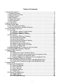
Table of Contents
1. Product Description...................................................................................................... 6
1.1 Product Features ................................................................................................. 6
1.2 System Requirements ......................................................................................... 7
1.3 Packet Content..................................................................................................... 7
1.4 Specification ........................................................................................................ 8
1.5 Front / Rear Panel ................................................................................................ 9
1.6 LEDs Definition .................................................................................................... 9
1.7 Connectors........................................................................................................... 9
2. Install Hard Disk.......................................................................................................... 10
3. Connect to the NVR .................................................................................................... 16
3.1 Use Device Search Utility.................................................................................. 16
3.2 Access NVR with its default IP address........................................................... 20
4. Live View (Web Interface)........................................................................................... 21
4.1 Live View ............................................................................................................ 21
4.1.1 Retrieve camera’s video stream............................................................. 21
4.1.2 Retrieve camera’s status ........................................................................ 22
4.1.3 Perform Sequence Viewing .................................................................... 22
4.2 PTZ Control ........................................................................................................ 23
4.2.1 Perform PTZ Preset Viewing................................................................... 23
4.2.2 Preset Point Viewing ............................................................................... 24
4.2.3 Auto Pan Viewing .................................................................................... 24
4.2.4 Preset Point Sequence Viewing ............................................................. 25
4.2.5 Live Video Controls................................................................................. 25
4.2.6 Display ratio and full screen................................................................... 25
4.2.7 Take a snapshot of a live video.............................................................. 26
4.2.8 Perform Digital PTZ ................................................................................. 29
4.3 Adjust Brightness / Contrast for the Live Video ............................................. 31
4.4 Change Web UI Display Language................................................................... 32
5. Playback (Web Interface) ........................................................................................... 33
5.1 Playback ............................................................................................................. 33
5.1.1 Methods to Search Playback Videos ..................................................... 33
5.1.2 Certain functions you can perform to the playback video................... 37
5.1.3 Take a snapshot of a playback video .................................................... 37
5.1.4 Adjust Brightness and Contrast for the Playback Video ..................... 40
5.2 Export Playback Videos to AVI Files................................................................ 41
5.2.1 Play Exported Playback Videos with NVR Media Player ...................... 43
5.2.2 Open Event Snapshot images with NVR Media Player ........................ 45
6. System Setup .............................................................................................................. 46
6.1 System Configurations ..................................................................................... 46
6.1.1 Network Settings ..................................................................................... 46
6.1.2 Time and Date .......................................................................................... 48
6.1.3 User Account ........................................................................................... 49
6.1.4 Group Privilege........................................................................................ 50
6.1.5 Disk Setup ................................................................................................ 51
6.2 Channel Configurations .................................................................................... 52
6.2.1 Add a Camera .......................................................................................... 52
6.2.2 OSD Settings............................................................................................ 55
6.2.3 PTZ Preset Settings................................................................................. 56
4
6.2.4 PTZ Preset Sequence .............................................................................. 57
6.2.5 Local Map Setting.................................................................................... 58
6.2.6 Google Map Setting ................................................................................. 60
6.3 Event Configurations ........................................................................................ 62
6.3.1 General Settings ...................................................................................... 62
6.3.2 DI Settings................................................................................................ 63
6.3.3 Event Servers........................................................................................... 63
6.3.4 Event Triggers ......................................................................................... 66
6.4 Recording Configurations ................................................................................ 68
6.4.1 General Settings ...................................................................................... 68
6.4.2 Schedule Recording ................................................................................ 69
6.5 System Options ................................................................................................. 71
6.5.1 Device Information .................................................................................. 71
6.5.2 Logs and Reports .................................................................................... 71
6.5.3 Maintenance............................................................................................. 71
6.5.4 Disk Status ............................................................................................... 73
6.5.5 USB Backup ............................................................................................. 73
7. Local UI from HDMI Output ........................................................................................ 76
7.1 Live View ............................................................................................................ 76
7.1.1 Login screen ............................................................................................ 76
7.1.2 Remote control ........................................................................................ 76
7.1.3 Live View .................................................................................................. 78
7.1.4 Side menu ................................................................................................ 79
7.1.5 Sequence view......................................................................................... 80
7.2 PTZ Control ........................................................................................................ 83
7.2.1 Add preset points .................................................................................... 84
7.2.2 Preset point sequence view.................................................................... 84
7.2.3 Manual Recording ................................................................................... 85
7.3 Take snapshot.................................................................................................... 86
7.4 PIP (Picture-in-picture) Event Video ................................................................ 87
7.5 Display video in its original size....................................................................... 88
7.6 Detail channel status......................................................................................... 88
7.7 Dashboard .......................................................................................................... 90
7.8 Playback ............................................................................................................. 90
7.9 Time Chart .......................................................................................................... 92
7.10 Export recorded data....................................................................................... 93
7.11 Power off .......................................................................................................... 95
5
1. Product Description
The NVR is designed for use within a surveillance system, and performs
recordings and playbacks pictures from network cameras in the system. It is designed
for small scale applications such as retail store. Up to 4 cameras can be connected via
a network and it is possible to record their camera pictures.
It is possible to perform the settings or operate the NVR using a web browser
installed on a PC connected to a network and live videos can be viewed on major
mobile devices through its web browser. Recorded video can be played back from
remote site by a PC.
It comes with a HDMI connector that allows users to connect the NVR directly to a
HDMI capable HDTV/monitor. It then can be operate with the bundled remote control
and mouse. The NVR is compatible with most major brand cameras and its ability to
automatically search and find the available cameras on the network can greatly reduce
the user's effort when configuring the system.
1.1 Product Features
Video/Audio:
HDMI/AV local display with remote controller or mouse
Simultaneous Recording and Live Video Streams
Up to FULL HD resolution for local display.
Supports M-JPEG / MPEG-4 / H.264 multiple compressions
Two-Way Audio function
Record:
Video recycle function makes the video recording in 24/7
Record 120fps @ 1920x1080
Manual or schedule recording of 4 IP cameras simultaneously
Exports record video file to AVI format
Management:
Web-Based and management utility for easy configuration
E-Map interface in web and utility configuration
Auto discover by management software
Smart IP camera search
Multiple languages support
Supports mobile phone remote view with Android, WinMo, Symbian S60, iPhone,
Blackberry 4.6
Manage multiple NVR with the bundle management software
English
Hardware:
Supports Real Time Clock (RTC)
HDMI/ RCA / USB interfaces supported
Auto power-on and recording after power recovery
Supports 3.5” SATA x 2 HDD
6
6
1.2 System Requirements
The following are minimum system requirements for the system to operate
Network Video Recorder (NVR):
Operating System
Windows® XP Professional (32 bit), Windows® Server 2003 (32 bit), Windows
Vista or Windows 7
Browser
Microsoft Internet Explorer 7 or above
CPU
Minimum Intel® Core2 Duo E6300 2.8GHz or higher (Core2 Quad is
recommended)
RAM
Minimum 1 GB of RAM, 2GB or above is recommended
Network
Minimum 10/100 Ethernet (Gigabit Ethernet is recommended)
Video Graphics Adapter
PCI-Express Standalone, 128MB Ram, minimum 1024x768, 16 bit colors. (256MB
is recommended, we highly recommend to work above the 1024 x 768 resolution
to get the full experience of the software)
. Make sure your display DPI setting is set to default at 96DPI
. To set DPI value, right-click on desktop, choose “Settings” tab >>
“Advanced” >> “General”
1.3 Packet Content
1 x NVR-420
1 x Remote Controller
1 x Power Cord
1 x Power Adapter
1 x RJ-45 Cable
1 x CD-ROM
1 x Quick Installation Guide
8 x HDD Screw
7
7
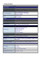
1.4 Specification
Product
NVR-420
Video/ Audio
Video Input
4 channels IP cameras
Video output
HDMI/ RCA local display, web interface
Resolution
Full HD/MegaPixel/FD1/CIF/QCIF
Local video display
Audio
Record
Recording Mode
Frame Rate/ Resolution
Export File Format
Storage Device
Vdeo streamming: H.264/MPEG4
30fps at 1920x1080, H.264, 8Mbps
Snapshot: MJPEG
Yes (G.711/G.726)
Web: Two-way
Local: One way
Manual, Schedule, Event
120 fps at 1920x1080
AVI
2 x 3.5” SATA hard disk connectors
Max. Capacity: 4TB (2TB per HDD)
System
Web-Based administration
Local mouse/remote controller
Network Time Protocol
Multiple users account
E-mail notification
System log
Firmware upgrade
Web Browser, HDMI/AV local output
Web Browser, local display
Firmware upgrade, USB mouse
Management
User Interface
E-Map
USB Interface
Network
Network Service
1 x RJ-45, 10/100, half duplex/full duplex autonegotiation
TCP/IP, DHCP, DNS, HTTP, FTP, NTP, SMTP, UPnP
Network File Protocol
Microsoft Networks (CIFS/SMB), Internet (HTTP), FTP
Ethernet
Hardware
Button
LED Display
Power
Operating Temperature
Dimensions (W x D x H)
Weight
Power, Reset
1 x Power
2 x HDD
4 x Channel
DC 12V, 4A, Max. 50/60Hz
5~40 Degree C
213 x 80 x 150 mm
0.8Kg
8
8
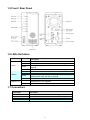
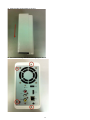
1.5 Front / Rear Panel
1.6 LEDs Definition
LEDs
Power
Color
Description
Green
Red
When NVR-420 is fully started
When NVR-420 is off, but power cord remains plugged in.
Blinking during system initialization, reboot, and firmware
upgrade
When NVR-420 is off and the power cord is not plugged in.
Disk is online.
Disk error.
Solid amber when NVR-420 is recording.
Blinking amber when the disk is recycling.
No disk or disk is offline.
Solid green when NVR-420 is online.
Blinking during event triggered.
Disconnect or no camera is configured.
Amber
Off
Green
Red
HDD1/2
Amber
Off
Channel 1~4
Green
Off
English
1.7 Connectors
Connector
Description
USB
Reset
HDMI
Ethernet
Connect your USB flash disk for firmware upgrade and backup.
Press and hold reset button for 30 seconds to factory default.
HDMI output
10/100 Mbps network.
9
9
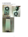
2. Install Hard Disk
1. Locate the screws highlighted above on the back of the NVR.
2. Use a Philips screw driver to release the screws.
3. Slide opens the case as shown above.
10
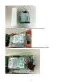
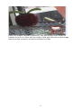
4. One side of the housing can be detached as shown above.
5. Install the bottom HDD by slide it in to the tray diagonally to avoid the tray separator.
6. Once the HDD is placed into the tray, you should see a gap between the HDD and the SATA
connector.
11
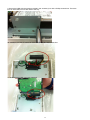
7. Attach the HDD to the SATA connector by sliding it towards the connector.
8. Make sure the screw holes on the HDD are aligned with the ones on the tray.
12
9. Secure the HDD with the screws provided in the accessory box with a Philips screw driver. There are
four for each HDD; two for each side of the tray.
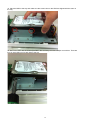
10. Install the top HDD by attaching it to the corresponding SATA cable first.
11. Make sure the HDD is securely attached.
13
12. Place the HDD to the tray and make sure the screw holes on the HDD are aligned with the ones on
the tray.
13. Secure the HDD with the screws provided in the accessory box with a Philips screw driver. There are
four for each HDD; two for each side of the tray.
14
14. Slide the side housing back to the unit.
15. Secure the housing with the screws highlighted above.
15
3. Connect to the NVR
There are various ways you can connect to the NVR and below are the
suggested methods for different network setup:
The NVR is placed in a network with a DHCP server: Connect to the
NVR by using “Device Search” Utility.
The NVR is placed in a network without DHCP server (or you are
connecting to it directly): Access NVR with its default IP (192.168.0.20).
3.1 Use Device Search Utility
If the NVR is placed in a corporate network or a local area network where a
DHCP server is already presented, please install the “Device Search” utility from
the bundled CD disk.
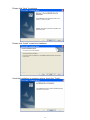
To begin, launch the “Device Search” utility from the CD and proceed with the
installation.
16
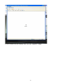
Please click “Next” to continue.
Please click “Install” to start the installation.
Once the installation is complete, please check the “Finish”.
17
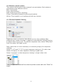
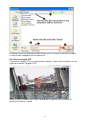
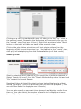
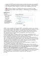
Please go to Start => Programs => NVR => Search NVR to run the search tool.
Then you will see the utility start search the network.
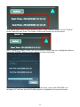
The NVR should be located and its IP address should be displayed: Doubleclick on it and the program should automatically access the NVR’s
web .administration page from your default browser.
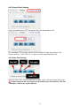
You may change NVR’s IP address by click on the button highlighted below.
You will be prompted for the NVR’s login information before proceeding to
change device’s IP address.
18
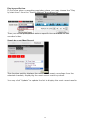
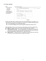
You may click on the button highlighted below to perform search again. Or
double-click on any of the search results to access NVR’s web administration
page.
Perform search again
Access NVR’s web administration page
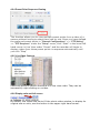
You should be prompted for the NVR’s username and password. Enter its
default username “admin” and password “admin” and then click ”OK” to
enter the system.
19
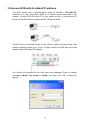
3.2 Access NVR with its default IP address
The NVR comes with a pre-configured static IP address “192.168.0.20”.
However, it is only used when there is no DHCP server presented in the
network. Connect the NVR and PC to your switch or hub, or connect the PC
directly to the NVR using a crossover CAT.5 Ethernet cable.
The PC that is connected directly to the NVR (or within the same local area
network) should receive an IP from it. Simply access the NVR from your web
browser with NVR default IP address.
You should be prompted for the user name and password. Enter its default
username “admin” and password “admin” and then click” OK” to enter the
system.
20
4. Live View (Web Interface)
4.1 Live View
The “Live View” page provides the following functions:
• Retrieve camera’s video stream
• Retrieve camera’s status
• Perform Live Sequence Viewing
• PTZ Control
• Perform PTZ Preset Sequence viewing
• Perform manual recording
• Take snapshot
• Receive audio of a video stream
• Send audio
• Control “Buzzer”
• Change web UI display language
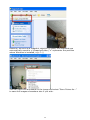
4.1.1 Retrieve camera’s video stream
The camera list is expanded and displayed on the Live View
page:
• Click “All” to display videos of all 4 channels
• Click on any camera to display video in single-view mode
21
4.1.2 Retrieve camera’s status
The camera list can show each camera’s current status. Each status is
represented with different colors:
Blue: Connected
Gray: Disconnected
Red: Performing event recording
Green: Recording (manual/continuous/schedule)
White: This channel is not configured with any camera
4.1.3 Perform Sequence Viewing
Sequence view is a function that allows you to view multiple video
streams from certain cameras in sequence automatically without having
to select them one by one. To perform sequence view, select “SEQ View”
from the upper-left hand corner
Next, select one or more camera(s) or camera group(s) for sequence
viewing:
Select "1-16" and "17-32" to start sequence viewing in 16-video view
Select "Group(x)" to start sequence viewing in quad view
Select "cameras" to start sequence viewing in single video view
Then, select dwell interval from the drop-down menu and click "Start" to
begin.
22
4.2 PTZ Control
PTZ control provides functions to pan, tilt, and zoom a PTZ camera as
well as the ability to adjust camera focus and iris.
Only PTZ capable cameras will be listed in the drop-down menu
The bar highlighted above controls the moving angle. Larger number
means bigger movement angle.
4.2.1 Perform PTZ Preset Viewing
There are three functions provided in the “Preset” section:
• Perform preset point viewing of a particular camera
• Auto pan a particular camera
• Perform preset point sequence viewing
In order to use this function, one must configure camera's preset points in "NVR
Setup" >> "Channel Configurations" >> "PTZ Preset" first
23
4.2.2 Preset Point Viewing
Start by selecting a PTZ camera from the drop-down list
Its available PTZ preset points will be listed in the drop-down list
shown below. Click "Go to" to move to the selected position.
4.2.3 Auto Pan Viewing
Use the Auto Pan control buttons to pan right, left and stop auto pan
Certain cameras do not support bi-directional pan movements. Use the
“Auto pan” button for such cameras
24
4.2.4 Preset Point Sequence Viewing
This function allows you to view multiple preset points from a video of a
camera without having to select them one by one. Once you have defined
the preferred preset points in “Channel Configurations” >> “PTZ Setting”
>> “PTZ Sequence” under the “Setup” menu, click “Start” in the lower-left
hand corner in Live View under “Preset” and the recorder will begin to
display videos from those preset points in sequence automatically until
you click “Stop”
4.2.5 Live Video Controls
Users can perform certain functions to a live view video. They can be
accessed by right clicking on a video.
4.2.6 Display ratio and full screen
By default, the videos are set to fill the whole video window, to display its
original size or ratio, use the button in the upper-right hand corner.
25
4.2.7 Take a snapshot of a live video
To take a snapshot of a live video, right-click on the video and select
"Take Snapshot". You are given with options to take 1 snapshot or 3
continuous snapshots.
A new window should display and load the snapshot image.
26
If the "3 continuous snapshots" option is chosen, the new window
displays snapshots and lets you view them individually by using the
"Prev", "Next" buttons shown above.
27
However, as soon as a snapshot selection is made, the snapshots are
automatically saved to x:\SnapshotFolder ("x" represents the partition
where Windows is installed, e.g: C:\)
You can right-click anywhere on the image and select "Save Picture As..."
to save the images somewhere else if you wish.
28
A dialog should be displayed that allows you to choose a directory/folder
of where the snapshot will be saved to.
4.2.8 Perform Digital PTZ
To perform digital PTZ on a particular channel, right-click anywhere on its
video and select "Digital PTZ".
Next, hold the mouse left button and draw a square on the video to
specify the zoom in area
29
Once the image is digitally zoomed in, use the mouse scroll button to
further zoom on or zoom out the image. Hold and left-click on the image
and move the mouse to move the zoomed in video.
30
4.3 Adjust Brightness / Contrast for the Live Video
You are able to adjust brightness of the live video from the right-click
menu.
31
4.4 Change Web UI Display Language
You can change the web UI display language from the current login
username link located at the upper-right hand corner. Click on the link
opens up a new window which displays detail information about the user
as well as a drop-down menu which lets you change the display language.
32
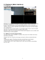
5. Playback (Web Interface)
5.1 Playback
Playback is a function that allows you to play one or more videos that were
previously recorded by a chosen recording method or due to an event
trigger. The NVR offers synchronized playback from up to 4 channels and
various types of search methods are provided to help you find the footage
you need quickly.
You can turn on or off the audio of a recorded video at your choice if audio
was also recorded during the recording of the video.
Playback video can be viewed in full screen and snapshots can be taken and
saved during a video playback.
5.1.1 Methods to Search Playback Videos
The NVR offers three methods to quickly help users find videos that were
previously recorded:
• Search by time: Specify a time range and search videos recorded within that
range
• Search by event: Find videos that were recorded due to event triggers
• Most Recent Events: Displays the most recent 15 events
• Play by start time: Enter a specific time a video was recorded to start playing
back the video
33
Search by time chart
1. Start by selecting which channel(s) you would like to perform a search
on.
2. Select “Search by time chart” from the “Search Method” drop-down list
and click “Go” to start the search
* Selected channels will be marked in red
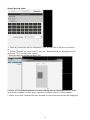
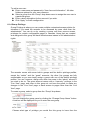
Results will then be displayed in a new dialog with a “Month/Channel” table
and boxes marked in dark gray represent videos found in those dates.
(*Videos from other cameras that are recorded on the same date will also be displayed)
34
Clicking on a cell box marked with gray will take you to the "day" view of
the selected month. Repeating the same step will eventually take you to
the "second" view (5sec per cell box). Right-click anywhere or the "Back"
button on the table will take you back to the previous view.
Click on the play button at anytime will start playing videos from the
beginning of the current time view (ex. if the table is in the "month" view,
click play will start playing from the first available clip of that month)
Search by event
Start by selecting which channel(s) you would like to perform a search on.
Select “Search by event” from the “Search Method” drop-down list and click
“Go” to start the search Results
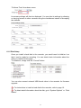
Results will then be listed like what is shown below (displays the oldest
record top down). Click on a particular result to start the playback. (*You
can click “Next Search” to display the next 15 results.)
You may also specify a new start time to search and display results from
then on. You can restrict the number of results to be displayed at once
(max. 30) and perform the search again
35
Play by specific time
If you know when a recording was taken place, you may choose the “Play
by start time” from the “Search Method” drop-down list
Then you will be prompted to enter a specific time and date for the
recorded video.
Search by event (Most Recent)
This function quickly displays the most recent event recordings from the
selected channels, displaying the most recent result top down.
You may click “Update” to update the list to display the most recent results.
36
5.1.2 Certain functions you can perform to the playback video
You can do the followings by right clicking on the playback video:
1. Play Audio
2. Snapshot
3. Export as AVI file
4. Digital PTZ
5. Adjust Brightness
6. Adjust Contrast
5.1.3 Take a snapshot of a playback video
To take a snapshot, right-click on the video and select "Take Snapshot".
You are given with options to take 1 snapshot or 3 continuous snapshots.
37
A new window should display and load the snapshot image.
38
If the "3 continuous snapshots" option is chosen, the new window displays
snapshots and lets you view them individually by using the "Prev", "Next"
buttons shown above.
However, as soon as a snapshot selection is made, the snapshots are
automatically saved to x:\SnapshotFolder ("x" represents the partition
where Windows is installed, e.g: C:\)
39
You can right-click anywhere on the image and select "Save Picture As..."
to save the images somewhere else if you wish.
5.1.4 Adjust Brightness and Contrast for the Playback Video
You are able to adjust brightness of the playback video from the right click
menu.
40
5.2 Export Playback Videos to AVI Files
User can export the recorded playback videos stored on the NVR to a local
computer and save them in AVI file format. The files can then be played on
the PC by a 3rd party media player such as VLC player or Windows Media
player. Once you locate the recorded videos with steps described in the
previous section, select "Export as AVI file"
A new dialog will pop up and allows you to specify the time frame (or length)
of the video you wish to export
41
You can alternatively choose to export the recorded video to JPEG images
by choosing the "Export as JPEG images" option.
Specify the Start time/End time (or export length) and click "Start" to begin
exporting. You will be notified once the process is completed successfully
42
The best way to view the exported video or JPEG images is to use the NVR
media player, which can be obtained from the same dialog window. Simply
click on the icon at the bottom (highlighted above), and a message box
should appear to let you open the media player directly, or save it to the
local hard drive for later use.
The exported AVI files (or JPEG images) will be saved under the C partition
(or the partition where Windows is installed)
* ffdshow is required in order to play the exported AVI file with Windows Media Player.
You can get it at “http://sourceforge.net/projects/ffd- show-tryout/” to download the “ffdshow_beta6_rev2527_20081219. exe”
5.2.1 Play Exported Playback Videos with NVR Media Player
You can also use the NVR Media Player to play the exported AVI files. This
can save you the trouble of installing third-party media player or codec
when playing the exported AVI videos.
The NVR Media Player will be automatically installed after the CMS software
43
is installed. You can find it in the Windows Start menu.
Click “Open” >> “AVI File”
Locate the exported AVI file, and click “open”. (normally under
“C:\ExportFolder)”
The video will then start playing
44
5.2.2 Open Event Snapshot images with NVR Media Player
The NVR sends snapshots that are taken when an event occurs to a
destined FTP server or mail recipient. These types of snapshot images are
saved in a proprietary image file format, h4i or p4i, and can only be opened
by the NVR media player.
To do so, Select “Open” from the top menu then select “Image File”. A new
dialog should be displayed which lets you locate the image file.
45
6. System Setup
6.1 System Configurations
The “System Configurations” page provides users options to setup the device
quickly and properly. After properly configuring all settings in all the sub-pages,
users should expect a fully working network video recorder that is ready to
manage cameras on the network. We will start by configuring its network settings
to make sure it works correctly in your network. Next, we will help you adjust the
system time so videos will be recorder with correct timestamp. To better secure
the system for unwanted disturbance, we will guide you on setting up user’s
account and privileges to prevent settings gets altered by users other than the
system administrator. Lastly, we will tell you what you should expect after installing
a hard disk and how to prepare the hard disk for the video recording.
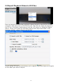
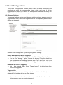
6.1.1 Network Settings
You need to adjust settings in this page for the device to work properly in your
network. It is critical that settings here are configured correctly based on your
network configurations so that the recorder can be administered through the local
area network and cameras can be connected from it.
By default, the recorder is set to obtain IP address from DHCP server, it should be
sufficient in most network environments, and most likely you should not need to
alter anything in this page. To locate the recorder, simply use the IP Utility with
steps described in page 13.
If you wish to set the recorder to use a static IP address in your local area network,
1. Choose “Static IP” from the “Connection Type” drop-down menu
2. Enter the IP address, subnet mask, default gateway address and DNS server
address for the recorder
3. Enable “DHCP Server” under “DHCP Server” if you wish to use the recorder as
a DHCP server, or leave it disabled if there is already a DHCP server in the
network .
4. Click Apply for the settings to take effect.
The recorder can detect the presence of a DHCP server upon startup. It sets
itself to use static IP address if there is no DHCP server currently presented in the
46
network. Its DHCP server function is also turned on at the same time to assign IP
addresses to cameras that are later connected to the network. You can manually
turn off the DHCP server function if you wish to use a separate DHCP server.
Change the recorder’s IP address would require the recorder to restart.
Restart the device under “system Options” >> “Maintenance” for the settings to
take effect.
DDNS Service
DDNS, which stands for “Dynamic DNS”, is a method, protocol, or network
service that provides the capability for a networked device, such as a router
or computer system (in this case, the NVR) using the Internet Protocol
Suite, to notify a domain name server to change, in real time, the active
DNS configuration of its configured hostnames, addresses or other
information stored in DNS.
A popular application of dynamic DNS is to provide a residential user’s
Internet gateway that has a variable, often changing, IP address with a well
known hostname resolvable through standard DNS queries.
This is useful if the NVR is placed on the Internet with a dynamic public IP,
which once the DDNS is properly setup, users can access the NVR remotely
with the DDNS domain name without worrying if the IP has changed or not.
*Please make sure a valid DNS server has been configured under the “Network
Setting” page in order for this function to work properly.
*The NVR currently only works with free DDNS service provided by “DynDNS”. For
more information, please go to www.dyndns.com
*If the NVR is placed behind a router or Internet gateway, please make sure port
forwarding for port 80 is configured on the router or the gat- way in order for the DDNS
function to properly register with the service. It’s often suggested to use the DDNS
function in the router/ gateway for such case instead.
*Once you have the DDNS function successfully up and running, please DO NOT
forget to configure port forwarding for the NVR web port (default 80) and the streaming
port (default 9877) in the router/gateway for remote viewing. You can then type in
http://yourddnsdomain in the browser to access the NVR remotely for
live view.
47
6.1.2 Time and Date
Set the time and date by selecting the time zone according to your location. It is
imperative that you set the recorder’s time correctly to avoid the following errors:
Incorrect display time for playback videos.
Inconsistent display time of event logs and when they actually occur.
After selecting the time zone, choose an option below to set the recorder time.
Manual - Use the drop-down list and configure the time manually.
Sync with NTP server - enter the hostname or IP address of a valid NTP
server and set how often the recorder should synchronize the time with the
recorder by using the “Update interval” drop-down menu.
Sync with PC - Check this option to synchronize the recorder time with the
PC that you are currently using to access the recorder.
48
6.1.3 User Account
The recorder can be accessed by multiple users simultaneously. You can add,
remove, and edit users by using options provided in this page to keep user
information organized. Each recorder comes with a built-in “admin” account with
password “admin”. It’s highly recommended to change the password upon your
initial login.
To change the password of the “admin” account:
1. Click and highlight the “admin” account in the account list and click
“Edit”.
2. Its information should be displayed in “User Account Information”.
3. Enter a new password in the “Password” field and enter it again in
“Confirm Password”.
49
To add a new user:
Enter a username and password in “User Account Information”. All other
fields are optional for your own reference.
Select a group from the “Group” drop-down menu to assign the new user to
a particular group.
Enter a short description for the account if you wish.
Click “Apply” to finish configuration.
6.1.4 Group Privilege
Group Privilege is where you can create multiple customized access policies for
situations if you need the recorder to be accessed by users other than the
administrator. You can do so by creating a group, and then remove access
privileges for certain configuration pages or cameras. Users that are created
and assigned to this group will have limited access instead of full administration
rights.
The recorder comes with seven built-in groups and five built-in privilege profiles,
except the “admin” and the “guest” accounts; the other five groups are fully
customizable or you can simply assign a group with one of the default privilege
profiles. You can, however, assign more than one users to the “admin” account if
you wish to do so. The guest account comes with a “view-only” privilege in the
“Live View” page, and users in this group do not have the power to make any
changes in the “Live View” page or have access to pages other than the “Live
View” page.
To create a group, select a group from the “Group” drop-down.
You can change the group name by clicking the “Change Group Name” button.
A text box will be displayed for you to enter the new group.
Choose what type of privilege you would like this group to have from the
50
“Privilege Type” drop-down menu.
Its access privilege will then be displayed. You can alter its settings by allowing
or denying access to other cameras using the checkboxes instead of accepting
the defaults.
6.1.5 Disk Setup
Once you install a hard disk to the recorder, you would need to initialize it so
that it can be ready for recording. You can obtain basic information about the
disk you installed in this page.
To initialize it, simply click the “Format” button.
You can also connect external USB thumb drive to the recorder for firmware
upgrade.
For instructions to install a hard disk to the recorder, refer to page 10.
To obtain detail information about the disk, go to “System Options” >> “Disk
Status”.
51
6.2 Channel Configurations
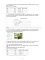
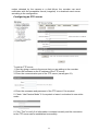
6.2.1 Add a Camera
The NVR provides two options for adding a new camera. Users have the option
to let the recorder automatically find the cameras or it is possible to enter
camera’s information and add it manually.
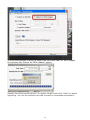
Automatic Search:
1. Click the “Search” button to perform the camera search. You should be
prompted to install Active Control component in order for the search to function
properly. Go ahead and click “Install”
2. After that, the search should begin and its status should be displayed.
52
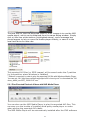
3. Found cameras should be listed and simply select a camera from the list and
press “Configure”.
4. Its corresponding information should be displayed in the “Camera
Information” section. Enter its username and password and select the channel
ID and name the camera.
5. Click on “Detect” to establish connection between the recorder and the
camera. If connection establishes successfully, camera’s detailed information
should be polled and displayed as below.
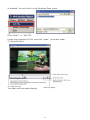
6. Adjust its video format, frame rate, resolution or bitrate…etc if you wish. You
can also click on the “Preview” to preview the live video of the camera.
Click “Add” to finish adding the camera.
If cameras are marked with “*” in the search result, it means those cameras
are already configured and connected to NVR.
53
Add a camera manually
Simply follow the instruction described above but instead of using the “Search”
function, enter the camera’s IP address and credential in the “Camera
Information” manually, then follow step 5 and 6 described above.
2.
1.
Enter manually
54
6.2.2 OSD Settings
The OSD (On Screen Display) allows users to add informational text message and
embed it onto the video. By default, this function is turned off. To add texts to one
or more videos.
1. Select a camera you would like to add text to and choose “Display OSD”.
2. Choose one or more display options if you would also like the recorder to
automatically embed the system time or the frame rate for you. Or simply choose
to display a custom message of your own.
3. Next, define where the text will be displayed by either entering an X/Y
coordinate or use the system pre-defined position from the drop-down menu.
4. Click on the “Preview” button to see the preview of your setting and click “Apply”
to save the configuration.
.
The texts can be further adjusted with
changes to different size, color or font so
they can be more visible on the video.
55
6.2.3 PTZ Preset Settings
The recorder supports PTZ cameras and can set multiple preset points or
retrieve and manage preset points that are set in the camera. This is helpful if
you need to monitor multiple spots in one area from a particular camera.
1. To set up PTZ preset points, select a camera from the “Camera” drop-down
menu and click “Add”.
2. Select a position number for the preset point from the “Position Number”
drop-down menu and fill in a name in the “Position Name” field for easier
identification.
3. Use the PTZ control provided in the configuration page to set the preset point
and set the position as the “HOME” position if you wish.
4. Click “Apply” to save the configuration.
56
6.2.4 PTZ Preset Sequence
Once you have multiple preset points defined for a camera, it is convenient for
monitoring to set up the sequencing viewing among those preset point and let
the recorder automatically switch between them for you.
To configure preset sequence for a camera,” select a camera from the
“Camera” drop-down menu.
The available preset points should be listed in “Camera Presets” section.
Pick the ones you like for sequence viewing and press the “->” button to move
them to the “Adjust Position” section, then use the up and down buttons to
adjust their sequences.
Finally, select a dwell time from the drop-down menu and click “Apply” to save
the configuration.
57
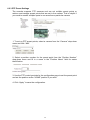
6.2.5 Local Map Setting
E-Map monitor is a function that alerts users whenever there is an event
triggered (e.g. motion detected) from a camera with a geographical perspective.
With this function, users can quickly identify which camera has detected an
unusual event and where this event is happening. This function works by
incorporating the event detection function as well as the recording function,
which, as a result, helps users take all the necessary actions when an unusual
event occurs.
To replace the map, click “Browse” button to locate the new map image file from
the local PC and then click “Upload”.
58
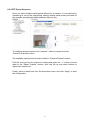
Then click and drag the camera icon to move the camera to define its location.
Access the “Local MAP Monitor” page from the upper-right hand corner menu.
When the NVR receives an event triggered from any of the cameras, their
videos will be displayed on the E-Map and you can double-click on the video to
enlarge it.
59
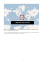
6.2.6 Google Map Setting
The Google Map monitor is a similar function to the aforementioned E Map
monitor. It is useful if you are managing multiple cameras from different
locations.
To configure locations of each camera, first determine the location you’d
like to place the camera to on the map. You can do so by:
1. Zoom in to a smaller area by using the zoom control bar on the map
2. Zoom in to a smaller area by using the mouse scroll button
You can also go to a specific place on the map by entering its address or
the name of the place in the “Address or places of interest” field
60
Once the location has been determined, click and drag the camera icon to
move it to the desired location
* The Google Map Monitor requires active Internet connection and can not be used in
conjunction with the regular E-Map monitor function.
61
6.3 Event Configurations
The “Event Configurations” section allows users to define conditions that
constitute an event, its corresponding trigger action and when it will be
triggered. Such setting can reduce the management overhead and notify the
administrator only when it’s necessary.
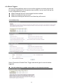
6.3.1 General Settings
The general settings section can help you quickly configure when an event is
triggered, how often events are triggered and the corresponding actions when
events are triggered.
Start the event configuration by defining the general settings:
Define when an event will be triggered.
Choose “Always” or “Only during…” under “Event Trigger Duration”.
For the “Only during…” option, choose the days by using the check-box
and then define the time range in those days in the “Start Time” and “End
Time” fields that you would like the event trigger function to be enabled.
How often an event is triggered
Set a time interval under “Event Trigger Interval” to define how often
events are triggered.
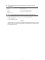
Trigger action
Now that you have the event trigger duration and interval defined, choose
what action to be taken during an event trigger:
You can choose to have the recorder send out the first few frames of the
video recorder upon an event is triggered.
62
You can also choose to have the recorder send out a warning message in
e-mail or in txt file format and upload it to a destined FTP server.
6.3.2 DI Settings
This function allows users to manage camera’s digital input port right from the
recorder. You can setup the recorder to receive triggers from a particular
camera’s input port.
1. For cameras that come with physical digital input port, their port will be listed
in the far left drop-down menu.
2. Pick the desired channel for DI mapping, and then select the camera’s input
port from the drop-down menu.
3. Select the trigger condition from the “Condition” drop-down menu.
4. Finally, define the trigger duration.
The recorder does not control camera’s input port in a way to let you pair
recorder itself with a camera’s input port for event receiving.
The recorder only acts as a medium for pairing up input ports between cameras
and the recorder.
Only connected cameras will be displayed in the list.
Some cameras only allow one trigger source be configured at a time, e.g.: if
the camera has the motion detection function turned on, its digital input will
be disabled and vice versa. Under such circumstance, if you set to use camera’s
digital input port as the event trigger source, you will not be able to select
motion detection as the trigger source for this camera under “Event
Configurations” >> “Event Trigger” setup page.
6.3.3 Event Servers
Event servers are to be used with event trigger actions. In case of unusual
63
motion detected by the camera or a disk failure, the recorder can send
notification with the acceptable format (image/txt) to a destined event server
according to the configuration.
Configuring an FTP server
To add an FTP server,
1. Start by giving a name to the server that you are adding to the recorder.
2. Enter the hostname or the IP address of the FTP server.
3. Enter the communication port of the FTP server (usually port 21).
4. Enter the username and password of the FTP server if it’s required.
5. Check “Use Passive Mode” if it’s required or leave it unchecked to use active
mode.
6. Click “Test” to verify if all information is entered correctly and the connection
to the FTP server can be established successfully.
64
7. Click “Apply” for the settings to take effect.
If you wish to edit/remove/enable/disable an FTP server, click to highlight one
from the profile list and choose the corresponding action button.
Configuring an SMTP server
1. Enter the hostname or the IP address of the SMTP server.
2. Enter the port of the SMTP server.
3. Specify the sender’s name in the “Sender’s name” field.
4. Enter the sender’s e-mail address.
5. Check “Enable Authentication” and enter the username and password of the
SMTP server and it requires authentication.
6. Click “Apply” to save the configuration.
*The NVR supports SMTP servers that use base64 or MD5 authentication
methods.
* 3rd party free E-mail services such as Gmail, Hotmail, or Yahoo mail are
not supported.
65
6.3.4 Event Triggers
We have finished defining how an event will be triggered and which servers will
be receiving notifications in the previous two sections, now we can finish up the
event configuration by setting.
Which channels will have event trigger function enabled.
What is considered to be an event.
Where the warnings will be sent to and how they will be sent.
Select Channels to Enable Event Trigger and which type of event should be
triggered.
Use the check box to enable event trigger on the desired channels.
66
Define which system events should trigger the recorder to send out
notifications
Define how the notifications will be sent and where they will be sent to.
* Event trigger may not work for cameras that are placed outside of your local
network or on the Internet until the UPnP Port Forwarding” is enabled in both
the NVR and the router.
67
6.4 Recording Configurations
The “recording configurations” gives users the overall control of how and when a
recording is performed and the quality of different types of recordings performed on
each channels. It can help the recorder to operate with sufficient system resource by
performing recording only when it’s necessary with adjustable recording frame rate.
6.4.1 General Settings
You can define the following in “General Settings”:
Pre-Alarm/Post-Alarm recording length
Recording frame rate
Keep the record video with previous days
Enable/disable different recording types on different cameras
Enable/disable audio recording
The “recording configurations” gives users the overall control of how and when a
recording is performed and the quality of different types of recordings performed on
each channels. It can help the recorder to operate with sufficient system resource by
performing recording only when it’s necessary with adjustable recording frame rate.
Recording frame rate allows you to set different frame rate for different types of
recording instead of recording at one frame rate only. Use the drop-down menu and
select one of the pre-defined frame rates for a particular recording type.
68
Keep video allows you to set the NVR keep the record video in previous days.
The section at the bottom allows you to turn on or off a particular recording type on
any channels.
You can check the box the enable NVR audio recording function.
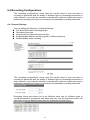
6.4.2 Schedule Recording
Here you can define the time range of the schedule recording for all channels.
To configure a schedule recording:
1. Use the “Camera” drop-down menu and select a camera first.
2. You can use the schedule table to set the time range. Click the cell boxes then
move the curser horizontally lets you set what hours to perform recording during a
day. Click and move vertically lets you set what days to perform recording at a
specific time.
69
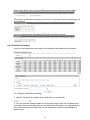
* Each cell box represents 15 minutes of time. Click one or more boxes to omit
consecutive recording.
3. You can also use the “Quick Configuration” to define recording time range instead
of clicking cell box one by one on the time table. Simply check what days you would
like to perform recording and specify the recording duration by either choosing “All
Day” or enter a start and end time for specific recording duration.
4. Select the “Copy to” option if you would like to set the same recording schedule to
other camera or all of the cameras.
70
6.5 System Options
System Options gives users a glance of the overall system status and allows users to
perform maintenance tasks such as upgrading firmware, restore/backup device
settings or reboot device ….etc.
6.5.1 Device Information
The “Device Information” provides the general information of the device such as
firmware version and system time. It also provides information of the current network
settings and status.
6.5.2 Logs and Reports
“Logs and Reports” keeps a record of what’s been happening to the device and
provides basic information for troubleshooting.
6.5.3 Maintenance
“Maintenance” provides functions for users to:
Reboot the NVR when necessary.
71
Reboot cameras directly from the NVR.
Perform Firmware Upgrade.
Backup the NVR’s settings to a local hard drive.
Restore the NVR’s settings from a previously saved configuration file.
Reset the NVR’s settings to their factory default values.
Reboot the NVR
Reboot NVR-401 after you upload a new firmware. You would need to manually
reboot the system for the new firmware to take effect. Such process would prevent a
recording from getting interrupted because the system would not automatically reboot
itself after the new firmware is loaded onto the recorder.
Simply click “Restart” to begin the reboot process and confirm the action.
The restart process should be displayed and you should be prompted back to the
“Maintenance” page after it is complete.
Reset the NVR to Factory Default
To reset the recorder back to its factory default, click “Default” button and begin the
process.
72
The process should be displayed and you should be prompted back to the
“Maintenance” page after it is complete.
6.5.4 Disk Status
“Disk Status” gives you more detailed information of the hard drive that is currently
installed in the NVR.
“Disk Status” gives you a more detailed information of the hard drive that is
currently installed in the NVR.
6.5.5 USB Backup
It’s a function that allows users to backup the recording data in its database file
format (not AVI) to the externally connected USB hard disk.
You can check the “Disk Status” page under “System Options” to see if the USB
disk has been detected by the NVR. If it's available, it will also be in the USB HDD
drop-down menu in the USB backup page.
* It needs a USB disk containing free space larger than 100MB.
73
Once it’s detected, go back to the “USB Backup” page and it should be available
for further configuration
The USB hard disk(s) will be listed in the drop-down menu displaying the
remaining disk space. Make your selection from the drop-down menu if you have
more than one disks connected to the NVR.
Next, select channels, which you would like to backup the recording data from.
Maximum 4 channels can be selected at once
74
Things to pay attention to the USB Backup function
Limitation:
• It does not support USB Hub extend the number of HDD connected to the NVR
• Only one backup process can be performed at a time
• Maximum 4 channels can be selected for backup
• Only FAT32 USB hard disk is supported for backup
• The USB hard disk needs to have more than 100MB remaining space
• If multiple partitions are presented in one disk, only the first partition will be
detected and used for backup Process:
• Progress will be displayed on the UI
• If the backup process gets interrupted, which the process stops at a point of
time that is before the “END Time” user defined, such time will be displayed on
the UI
• A folder will be automatically created in the USB hard disk with a name format
like 0028687831_20100610151515_2010060511 0010_20100606110010
(MAC_backupbuttonclicktime_starttime_endtime)
Note:
• Please plug in the USB HDD only after the NVR is fully started, or the HDDs will
be incorrectly mounted.
75
7. Local UI from HDMI Output
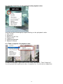
7.1 Live View
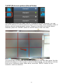
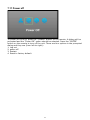
7.1.1 Login screen
You should be prompted with the login screen first when the NVR is fully started.
1. Power button
2. System Time
3. Username/Password
4. Display language selection
5. Virtual keyboard
By default, the focus should be on the username field.
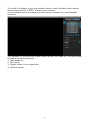
7.1.2 Remote control
76
Simply use the directional buttons on the remote to move between the keys on
the virtual keyboard. If you have a USB mouse plugged into the NVR, a mouse
cursor will appear on the screen and you can use the mouse to select keys on the
virtual keyboard as well. Press the "ENTER" button on the remote to make the
selection.
Enter the default username "admin" by using the virtual keyboard. When done,
select the "Enter" button on the virtual keyboard and the focus should be moved
to the password field.
After the default password "admin" is entered as well, select the "Enter" button
on the virtual keyboard again and the focus should be moved to the "Log in" icon.
Press the "ENTER" button on the remote to log in.
Turn on Audio
The local UI is capable of playing audio coming from the camera side, but It's not
77
turned on by default. To turn on audio from the current viewing channel, press
the "AUDIO" button on the remote. Press it again to turn off the audio.
Full Screen
To view video in full screen, press the "Right" button on the remote and move
the selection focus to the full screen icon (as shown above). Once selected, press
the "ENTER" button on the remote to enter full screen view. Click the "BACK"
button on the remote control to exit.
Alternatively, you can quickly go into full screen mode by pressing the "FULL
SCREEN" button on the remote. Press the "BACK" button to exit.
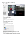
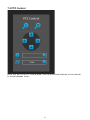
7.1.3 Live View
The Local UI basically provides the view functions of both live video and playback
video. The Local UI provides viewing video of 1 channel at a time, both live and
playback.
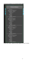
1. Top bar (the power, logged in user, system time and dashboard are placed in
this area)
78
2. Video area
3. Functions for live video (From top down: start/stop manual recording, take
snapshot, set location of the "Picture-in-picture" live event video coming from
other channel)
4. Main menu
5. Channel list including status and start sequence viewing
6. From top down: full screen, display video in its original size, channel status
7. PTZ control (Pan, tilt, zoom, add preset point, preset point sequence viewing)
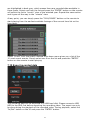
7.1.4 Side menu
79
By default, the selection focus should be on "Channel 1' on the Channel List. The
side bar is basically divided into three sections. At any point, you can use the
"Left" or "Right" button on the remote to quickly move to each section.
For example, if the selection focus is currently on "Channel 1" (or anywhere in
the section "1"), press the "Left" button on the remote will move the focus to the
"Manual recording" icon in section "2". Simply use the "Up" and "Down" buttons
on the remote to move between icons in one particular section.
Use the "Up" and "Down" buttons on the remote to select a channel on the
"Channel List" and press the "ENTER" button on the remote to make the selection.
Alternatively, if a USB mouse is connected to the NVR, you can use the mouse
and move the cursor to a channel and left-click to make the selection.
You can also use the channel selection buttons on the remote to quickly jump to
a desired channel.
The small dots on the side of the "Channel List" provide the current status of
each channel:
* White: Disconnected
* Blue: Connected
* Green: Recording
* Dark grey: Not configured
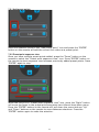
7.1.5 Sequence view
If the current selection focus is on "Channel 4", press the "Down" button on the
remote should move the focus to the "Sequence viewing" icon. Press the "ENTER"
80
button on the remote will start sequence viewing between all available channels
with default 5-second interval. Press the "ENTER" button on the remote again will
stop it.
When the focus is on the "Start/stop sequence view" icon, press the "Right"
button on the remote will move the focus to the sequence interval drop-down
menu.
Press the "ENTER" buttn on the remote should display all options in the drop-
81
down menu. Use the "Up" and "Down" buttons on the remote to move between
selections and press the "ENTER" button to select the new interval.
You can also quickly start/stop sequence viewing by using the "SEQ" button on
the remote.
If the selection focus is on either the "Sequence view" or the "Sequence interval",
press the "Down" button on the remote should move the focus to the "Zoom"
icon in the PTZ control area.
82
7.2 PTZ Control
Once you are in the PTZ control area. Use the directional buttons on the remote
to move between icons.
83
7.2.1 Add preset points
Move the selection focus to the "Add preset point" icon and press the "ENTER"
button on the remote will add the current live video as a preset point.
7.2.2 Preset point sequence view
Once you have multiple preset points added, press the "Down" button on the
remote to select the "Preset point sequence view" icon. Press "ENTER" button on
the remote to start sequence view between previously added preset points. Press
"ENTER" again to stop.
When the focus is on "Preset point sequence view" icon, press the "Right" button
will move the focus to the preset point sequence view interval drop-down menu.
Press the "ENTER" button on the remote will pull down the menu and use "Up"
and "Down" buttons on the remote to move between selections. Press the
"ENTER" button again to make the selection.
84
At any point in Live View, you can enter the PTZ mode by:
1. pressing the "PTZ" button on the remote
2. Use the directional buttons to simulate pan, tilt, zoom actions as well as
jumping through preset points.
7.2.3 Manual Recording
85
Recording can be manually started when viewing live video. If the selection focus
is somewhere in the green highlighted area shown above, press the "Left" button
on the remote will move the focus to the manual recording icon. Press the
"ENTER" button on the remote to start recording right away.
You should see an on-screen text notification indicating the recording has been
started.
Alternatively, you can press the "REC" button on the remote start recording of
the current viewing channel right away. Press it again to stop.
7.3 Take snapshot
Before taking a snapshot of the live video, please make sure a FAT32 formatted
USB drive is plugged into the NVR. If you had "Manual recording" icon selected,
press the "Down" button on the remote to select the "Snapshot" icon. Press the
"ENTER" button on the remote to take a snapshot.
You should see an on-screen text notification indicating that a snapshot of the
video has been taken.
86
7.4 PIP (Picture-in-picture) Event Video
The local UI provides live video view of 1 channel at a time. However, you can
set a PIP (Picture-in-picture) area on top of the live video, which displays video of
another channel when an event occurs. Once you have the icon shown above
selected, press the "ENTER" button to set PIP area on the live video.
You should see an area with blue border displayed on the live video area. Use the
directional buttons on the remote to select a desired area. You are able to choose
from up to 9 different areas. When done, press the "ENTER" button on the
remote to confirm selection.
87
7.5 Display video in its original size
By default, the video is scaled to fill the entire video area. To view the video in its
original size, select the icon shown above and press the "ENTER" button on the
remote to display the video in its original size.
7.6 Detail channel status
Select the icon shown above and press the "ENTER" button on the remote will
give you a detail current status of all four channels.
88
Press the "BACK" button on the remote to dock it away.
89
7.7 Dashboard
The dashboard provide a detail overview of the system wide information, such as
network settings, disk status, and channel status. Press the "BACK" button on the
remote to exit.
The dashboard is located in the upper-right hand corner and presses the "Up"
button on the remote until the selection focus is on the dashboard icon. Press the
"ENTER" button to enter dashboard.
7.8 Playback
90
To switch to Playback, move the selection focus to the Playback button shown
above and press the "ENTER" button on the remote.
You can always use the remote to quickly switch between Live and Playback
functions
The Playback UI provides the similar layout as the Live video UI. They also share
the same following functions:
1. Take snapshot
2. Full screen
3. Display video in its original size
4. Channel status
91
The NVR is able to play recorded video 1 channel at a time. To search for
playback video, select a channel from the "Channel List" first and select a search
method from the drop-down menu highlighted in the above picture.
There are three different search methods to help you locate the recorded videos.
7.9 Time Chart
Select the "Time Chart" option will display a list in "year". Notice certain years
92
are highlighted in dark grey, which means there are recorded data available in
those years. Select one from the list and press the "ENTER" button on the remote
will switch the list to "month" view of the selected year. Repeat the same action
and it goes all the way to the "minute" view.
At any point, you can simply press the "PLAY/PAUSE" button on the remote to
start playing from the earliest available footage of the current time list on the
time chart.
Select "Event" from the search method drop-down menu gives you a list of the
15 most recent events. Simply select one from the list and press the "ENTER"
button on the remote to start playing.
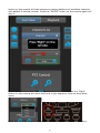
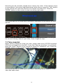
7.10 Export recorded data
The recording data can be exported to a USB hard disk. Please connect a USB
HDD to the NVR first before exporting the recording video. The export can only
be done during the playback of the recorded video. During playback, select the
"In/Out" button on the UI and press the "ENTER" button.
93
This sets a start time of the exported video. Press "ENTER" again on the "In/Out"
button sets the end time. The video of this time frame will be exported.
Next, press the "Right" button on the remote to select the icon highlighted above.
Press the "ENTER" button on the remote to start exporting.
The export progress will be displayed. When done, move the USB HDD to a
Windows PC and use the NVR media player to playback the exported video.
94
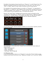
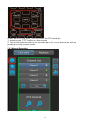
7.11 Power off
To power off the unit, press the "POWER" button on the remote. A dialog will be
prompted and the "Power Off" option should be selected. Press the "ENTER"
button on the remote to turn off the unit. There are four options in the prompted
dialog and they are (from left to right):
1. Log out
2. power off
3. Restart
4. Reset to factory default
95