1
installation and
Operation Manual
English
Installation and
Operation Manual
Legacy™
Pool and Spa Heater
Model LRZ Millivolt
Natural Gas or LPG
WARNING
If these instructions are not followed exactly, a fire or explosion may result,
causing
property damage, personal injury, or death.
FOR YOUR SAFETY: This product must be installed and serviced by a contractor who is gas safe registered and
HWB1 certified. Before installing this product, read and follow all warning notices and instructions that accompany
this product. Failure to follow warning notices and instructions may result in property damage, personal injury, or
death. Improper installation and/or operation can create carbon monoxide gas and flue gases which can cause
serious injury, property damage, or death. For indoor installations, as an additional measure of safety, Zodiac
Pool Systems, Inc. strongly recommends installation of suitable Carbon Monoxide detectors in the vicinity of this
appliance and in any adjacent occupied spaces. Improper installation and/or operation will void the warranty.
WARNING
Read this manual in its entirety. If these instructions are not followed exactly,
or explosion may result, causing property damage, personal injury, or death.
a fire
The GAS SAFETY (INSTALLATION AND USE) REGULATIONS 1998 as amended, place statutory requirements
on gas users.
H0316500 Rev E
This heater is certified to European requirements for use only as a swimming pool or spa heater. The heater must
not be used for any other purpose and must be installed and serviced by a qualified professional. The heater must
be operated strictly in accordance with the user's instructions and applicable laws.
If the heater is installed in a room, it must be separated from a living space, and adequate air supply and
ventilation must be provided and maintained.
Do not store or use gasoline or other flammable vapors and liquids in the vicinity of this or any other appliance.
Installation and Operation Manual | Legacy™ Model LRZM Pool/Spa Heater
ENGLISH
Page 3
Table of Contents
Section 1. General Information..................... 5
Section 5. Water Connections....................... 14
1.1 Introduction..................................................... 5
1.2 Consumer Information and Safety.................. 5
1.2.1 Spa/Hot Tub Safety Rules......................... 5
1.2.2 Swimming Pool Energy Saving
Tips............................................................ 6
1.3 Warranty......................................................... 6
1.4 Codes and Standards..................................... 6
1.5 Technical Assistance...................................... 6
1.6 Materials Installer Must Provide..................... 6
1.6.1 Materials for All Applications...................... 6
1.6.2 Materials for Special Applications.............. 6
1.7 Specifications................................................. 7
1.7.1 General Specifications............................... 7
1.7.2 Performance Specifications....................... 7
1.7.3 Dimensions................................................ 7
5.1
5.2
5.3
5.4
5.5
5.6
5.7
5.8
Section 2. Installation Instructions............... 7
Water Piping................................................... 14
Hydraulic Head Loss...................................... 14
Check Valve Installation................................. 14
Automatic Flow Control Valve........................ 14
Reversible Water Connections....................... 15
Connections at Heater.................................... 17
Pressure Relief Valve..................................... 17
Auxiliary Components, Chlorinators, Ozone
Generators, and Sanitizing Chemicals........... 19
Section 6. Electrical....................................... 19
6.1
6.2
6.3
Main Power.................................................... 19
Earth Bonding................................................. 19
Auxiliary Time Clock Wiring............................ 20
Section 7. Commissioning............................. 21
7.1
Heater Start-Up.............................................. 21
2.1 Introduction..................................................... 7
2.2. Statutory Information...................................... 8
2.3 General Installation Requirements................. 9
2.4 Field Assembly .............................................. 9
2.5 Location Requirements.................................. 9
2.5.1 Introduction................................................ 9
2.5.2 Clearances................................................ 9
2.5.3 Flooring...................................................... 10
2.5.4 Outdoor Installation................................... 10
2.5.5 Indoor for Natural Gas Installation
Only........................................................... 11
8.1 Normal Operation........................................... 21
8.2 Start-Up.......................................................... 22
8.3 Lighting and Shutdown Procedures............... 22
8.3.1 Lighting the Heater.................................... 22
8.3.2 Relighting the Heater................................. 24
8.3.3 Shut-Down Procedure............................... 24
8.4 Turning the Heater On/Off and
Setting the Temperature Control.................... 24
Section 3. Venting.......................................... 11
Section 9. Maintenance.................................. 25
3.1 Combustion Air Supply................................... 11
3.2 Flue System Type B11 (Indoor)...................... 11
3.3 Vent Pipe Sizing and General Installation ..... 12
3.3.1 Outdoor Installations.................................. 12
3.3.2 Indoor Installations (Natural Gas ONLY)... 12
3.3.3 Inspection and Replacement of Existing
Vent System with New Components ......... 13
Section 4. Gas Connections.......................... 13
4.1
4.2
4.3
Gas Supply and Piping................................... 13
Burner Pressure............................................. 14
Special Precautions for LPG.......................... 14
Section 8. Operating Instructions................. 21
9.1 Water Chemistry............................................. 25
9.2 Seasonal Care................................................ 25
9.2.1 Spring and Fall Operation.......................... 25
9.2.2 Winterizing................................................. 25
9.2.3 Spring Start-up.......................................... 26
9.3 Inspection and Service................................... 26
9.3.1 Owner Inspection....................................... 26
9.3.2 Professional Inspection............................. 26
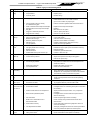
Section 10. Troubleshooting......................... 28
10.1 General Heater Troubleshooting.................... 28
Page 4
ENGLISH
Legacy™ Model LRZM Pool/Spa Heater | Installation and Operation Manual
Table of Contents (Continued)
Section 11. Professional
Maintenance and Service......... 30
11.1 General Information........................................ 30
11.2 Natural-Draft Combustion System.................. 30
11.3 Heater Components and Their Operation...... 30
11.4 Electrical Troubleshooting.............................. 31
11.4.1 Gas Valve.................................................. 31
11.4.2 Pilot Generator.......................................... 33
11.4.3 Fusible Link............................................... 33
11.4.4 Fireman Switch and External . .................. Interlocks................................................... 33
11.4.5 Limit Switches............................................ 34
11.4.6 Water Pressure Switch.............................. 34
11.4.7 Temperature Control Circuit....................... 34
11.4.7.1 ON/OFF Toggle Switch...................... 34
11.5 Adjusting the Water Pressure Switch............. 35
11.6 Temperature Rise........................................... 35
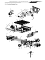
Section 12. Replacement Parts..................... 36
12.1
12.2
12.3
12.4
Ordering Information...................................... 36
Parts List........................................................ 37
General Exploded View.................................. 38
Detailed Exploded View................................. 39
Installation and Operation Manual | Legacy™ Model LRZM Pool/Spa Heater
Section 1. General Information
NOTE “Fresh water swimming pools and spas”
include systems that utilize saltwater chlorine
generator units, such as the Jandy AquaPure®
Electronic Chlorine Generator. Please ensure
that the salt content of the pool/spa does not
exceed 4000 ppm and water flow rate is within
110-470 lpm.
1.2
Spa or hot tub water temperature should never
exceed 40°C (104°F). Thirty-eight degrees
Celsius (38°C [100°F]) is considered safe for a
healthy adult. Special caution is recommended
for young children.
2.
The drinking of alcoholic beverages before or
during spa or hot tub use can cause drowsiness
which could lead to unconsciousness, and subsequently result in drowning.
3.
Pregnant women take note! Soaking in water
above 38.5°C (102°F) can cause fetal damage
during the first three (3) months of pregnancy
(which could result in the birth of a braindamaged or deformed child). If pregnant women
are going to use a spa or hot tub, they should
make sure the water temperature is below 38°C
(100°F) maximum.
4.
The water temperature should always be checked
with an accurate thermometer before entering a
spa or hot tub. Temperature controls may vary by
as much as 1°C (1°F).
5.
Persons with a medical history of heart disease,
diabetes, circulatory or blood pressure problems
should consult their physician before using a hot
tub or spa.
6.
Persons taking any medication which induces
drowsiness (e.g., tranquilizers, antihistamines, or
anticoagulants) should not use spas or hot tubs.
7.
This appliance is not intended for use by persons
(including children) with reduced physical,
sensory or mental capabilities, or lack of experience and knowledge, unless they have been given
supervision or instruction concerning use of
appliance by a person responsible for their safety.
Children should be supervised to ensure that they
do not play with the appliance.
8.
Prolonged immersion in hot water can induce
hyperthermia.
Consumer Information and Safety
The Legacy Model LRZ millivolt heater is
designed and manufactured to provide many years of
safe and reliable service when installed, operated and
maintained according to the information in this manual
and the installation codes referred to in later sections.
Throughout the manual safety warnings and cautions
are identified by the " " symbol. Be sure to read and
comply with all of the warnings and cautions.
1.2.1Spa/Hot Tub Safety Rules
WARNING
Elevated water temperature can be hazardous.
Consult heater operation and installation instructions for water temperature guidelines before setting
temperature.
Page 5
1.
1.1Introduction
This manual provides installation and operation
instructions for the Legacy Model LRZ millivolt pool
and spa heaters. Read these installation and operation
instructions completely before proceeding with the
installation. The installation must be conducted by a
qualified professional. While the entire manual should
be read by both the qualified professional installer
and the user, Sections 2 through 7 of this manual are
intended for the qualified professional installer. The
Operating instructions for the user begin in Section 8.
Consult the Zodiac factory, or local factory representative, with any questions regarding this equipment. The
instructions cover two (2) types of heaters as follows:
1. Type A (flueless) for outdoor installations only.
2. Type B11 flue for outdoor and indoor installations,
but must not be installed in a living space.
The Legacy model LRZ millivolt heater is a self
contained standing pilot unit and requires no external
power.
The Legacy Model LRZ millivolt heater
is specifically designed for heating fresh water
swimming pools and spas, and with proper installation
and care, will provide years of reliable service. Do not
use the heater to maintain pool or spa water temperature below 21°C (70°F). Do not use it as a heating
boiler or general service water heater. Consult your
dealer for the appropriate Zodiac products for these
applications.
ENGLISH
Hyperthermia occurs when the internal body
temperature reaches a level several degrees above the
normal body temperature of 37°C (98.6°F). Symptoms
include dizziness, fainting, drowsiness, lethargy, and
an increase in the internal body temperature. The
effects of hyperthermia include:
•
Lack of awareness of impending hazard
•
Failure to perceive heat
• Failure to recognize need to leave spa
• Physical inability to leave spa
• Fetal damage in pregnant women
• Unconsciousness resulting in a danger of
drowning
Page 6
ENGLISH
Legacy™ Model LRZM Pool/Spa Heater | Installation and Operation Manual
1.2.2Swimming Pool Energy Saving
Tips
Zodiac Pool Systems, Inc., ("Zodiac") offers the
following recommendations to help conserve fuel
and minimize the cost of operating your pool heater
without sacrificing comfort.
1. The American Red Cross recommends a
maximum water temperature of 25°C (78°F).
Use an accurate pool thermometer. A difference
of 2°C (4°F), between 26°C and 28°C (78°F and
82°F), will use as much as 40% more gas.
2. Carefully monitor the water temperature of your
pool in the summertime. You can reduce heater
usage due to warmer air temperatures.
3. Find the proper setting on the pool heater temperature control and use the Set Point Lockout
feature to discourage further adjustments.
4. Set the pump time clock to start the pump no
earlier than 6:00 AM during the pool heating
season. This is the time when nightly heat loss
balances.
5. If the pool is only going to be used on weekends,
reduce the heater temperature control setting by
8 or 10 degrees during the week. Reset it to the
25°C (78°F) level a day or so before you plan to
use the pool.
6. During the winter or when on vacation for longer
than a week, shut down the heater by following
the shutdown instructions found on the inside of
the heater.
7. Where possible, shelter the pool from prevailing winds with well-trimmed hedges or other
landscaping, cabanas, or fencing.
8. Always use a pool cover when practical. Besides
providing a valuable safety feature, a pool cover
will reduce heat loss, conserve chemicals, and
reduce the load on filter systems.
1.3
Warranty
The Legacy Model LRZ millivolt heater is sold
with a limited factory warranty. Details are specified
on the back cover of this manual.
Make all warranty claims to an authorized Zodiac
representative or directly to the factory. Claims must
include the heater serial number and model (this information can be found on the rating plate), installation
date, and name of the installer. Shipping costs are not
included in the warranty coverage.
The warranty does NOT cover damage caused
by improper assembly, installation, operation or field
modification. Also, damage to the heat exchanger by
corrosive water is NOT covered by the warranty. See
Section 9.1 for maintaining proper pool water
chemistry.
NOTE Keep this manual in a safe place for future
reference when inspecting or servicing the heater.
1.4
Codes and Standards
The Legacy Model LRZ millivolt heater has
been tested and certified by GL Industrial Services for
compliance with the Gas Appliance Directive (GAD;
2009/142/EC) and the latest version of European
Standard, BSEN 656. In addition, the product has
also been found to be in compliance with the essential requirements of the Low Voltage Directive (LVD;
2006/95/EC), and the Electromagnetic Compatibility
Directive (EMC Directive; 2004/108/EC).
All Zodiac heaters must be installed in accordance with the local building and installation codes as
per the utility or authorities having jurisdiction.
Any changes to the heater, gas controls, gas
orifices, wiring, draft hood, vent cap, or improper
installation may void the warranty. If change is
required to any of the above, consult the factory.
1.5Technical Assistance
Consult your local Zodiac distributor with any
questions or problems involving the specifications,
installation, and operation of your Zodiac equipment.
1.6
Materials Installer Must Provide
1.6.1 Materials for All Applications
The following items are needed and are to be
supplied by the installer for all Legacy Model LRZ
millivolt heater installations:
1. The correct size gas pipe to supply gas from the
meter to the heater (see Section 4.1).
2. A manually operated gas cock to be installed in
the gas line outside of the heater jacket.
3. Plumbing items needed to provide a sediment
trap (drip leg) in the gas line between the manual
gas cock and the heater (see Section 4.1).
1.6.2 Materials for Special
Applications
In addition to the items listed above, the following items are needed for special applications:
1. A factory authorized draft hood and any vent
pipe needed for indoor installations. See Section
3.3.2. Draft hoods are available from any Zodiac
distributor.
2. Primer and cement suitable for cementing PVC
pipe to the CPVC Zodiac unions supplied with
the heater.
Installation and Operation Manual | Legacy™ Model LRZM Pool/Spa Heater
3.
4.
A noncombustible platform for installation
on combustible surfaces (see Section 2.5.3).
Noncombustible bases are available from your
Zodiac distributor.
A factory approved vent cap for all outdoor
installations where wind conditions may cause
downdrafting. Approved vent caps are available
from your Zodiac distributor. See Section 12.2,
"Parts List", of this manual for the correct part
number.
1.7Specifications
1.7.1 General Specifications
1. Installation Location:
Certified for use:
Natural Gas: Indoor and Outdoor
LPG:
Outdoor Only
Refer to Table 1.
2. Minimum Clearance From Combustible Material
See Table 4.
1.7.2Performance Specifications
The Legacy Model LRZ millivolt heater performance specifications are shown in Table 2.
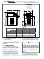
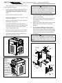
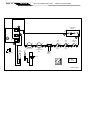
1.7.3Dimensions
See Figure 1 for a diagram showing the heater's
exterior dimensions and dimensions to critical connections on the heater.
ENGLISH
Page 7
Section 2. Installation Instructions
2.1Introduction
WARNING
This product must be installed and serviced by a
contractor who is licensed and qualified in pool
equipment. Improper installation or maintenance
can cause nausea or asphyxiation from carbon
monoxide in flue gases which could result in severe
injury, or death. For indoor installations, as an additional measure of safety, Zodiac strongly recommends installation of suitable Carbon Monoxide
detectors in the vicinity of this appliance and in any
adjacent occupied spaces. The heater may only be
installed in a room which complies with the appropriate ventilation requirements and which is separate from living areas.
Install the Legacy Model LRZ millivolt heater,
vent caps and draft hoods in accordance with the
procedures in this manual, local codes and ordinances,
and in accordance with the latest edition of the appropriate national code (see Section 1.4 "Codes and
Standards").
All gas-fired products require correct installation
to assure safe operation. The requirements for pool
heaters include the following:
1. Field assembly (if required)
2. Appropriate site location (clearances) and flooring
3. Sufficient combustion and ventilation air
4. Properly sized gas meter and piping
Table 1. General Specifications
LRZ
125
175
250
325
400
Water Capacity (L)
0,81
0,95
1,16
1,35
1,57
Minimum Water Flow (l/min)
75,7
75,7
94,6
113,6
113,6
Maximum Static Head (bar)
5,1
5,1
5,1
5,1
5,1
Maximum Outlet Temp (C)
40
40
40
40
40
Dry Weight (kg)
60
67
78
88
100
Gas Connection
3/4 in Bsp
(Rc 3/4)
3/4 in Bsp
(Rc 3/4)
3/4 in Bsp
(Rc 3/4)
3/4 in Bsp
(Rc 3/4)
3/4 in Bsp
(Rc 3/4)
Water Inlet Connection
2" unthreaded PVC
or CPVC
2" unthreaded PVC
or CPVC
2" unthreaded PVC
or CPVC
2" unthreaded PVC
or CPVC
2" unthreaded PVC
or CPVC
Water Outlet Connection
2" unthreaded PVC
or CPVC
2" unthreaded PVC
or CPVC
2" unthreaded PVC
or CPVC
2" unthreaded PVC
or CPVC
2" unthreaded PVC
or CPVC
Electrical Supply
220-240VAC, 50 Hz,
5 Amps Max
220-240VAC, 50 Hz,
5 Amps Max
220-240VAC, 50 Hz,
5 Amps Max
220-240VAC, 50 Hz,
5 Amps Max
220-240VAC, 50 Hz,
5 Amps Max
IP Rating
Flue Types
IPX4
Flue Type A (Flueless) for Outdoor Installations Only
Flue Type B11 (with Vent Cap for High Wind Areas) For Outdoor Installation Only
Flue Type B11 (with Draft Hood) for Indoor Installation Only
Appliance Category:
Natural Gas
LPG
I2H
I3P
Inlet Pressure (mbar)
Natural Gas
G20
LPG
G31 @ 37 mbar
Note: The LPG heat inputs apply up to an altitude of 600 m. Above this altitude, de-rate the heat input by 4% for every 300 m.
Page 8
ENGLISH
Legacy™ Model LRZM Pool/Spa Heater | Installation and Operation Manual
H
A
194 mm
406 mm
1041 mm
127 mm
1000 mm
264 mm
203 mm
724 mm
333 mm
Outdoor Flueless Heater Configuration
95 mm
Figure 1.
5.
6.
Indoor Open Flue Configuration with Draft Hood
Outdoor Flue Configuration with Vent Cap
Venting Dimensions
Model
Heater Width
Dim "A"
mm
mm
mm
mm
125
384
150
441
413
Vent Diameter
Outdoor
Dimension "H"
Indoor
Dimension "H"
175
460
150
457
613
250
578
175
464
641
325
683
200
479
673
400
822
230
546
699
General Configuration
Proper electrical wiring (if required)
Adequate water flow
This manual provides the information needed to
meet these requirements. Review all application and
installation procedures completely before continuing
the installation.
2.2. Statutory Information
It is the law that all gas appliances are to be
installed only by competent persons (e.g., registered
members of Gas Safe) in accordance with the Gas
Safety (Installation and Use) Regulations, latest
published version of BS6798, BS5440 Pt. 1 and
Pt. 2, BS6891, and BS5482 Pt. 2. Failure to install
appliances correctly could lead to prosecution.
The Legacy heater, as supplied, has been tested
and certified by Gas Appliance Directive (GAD;
2009/142/EC) and the latest version of European
Standard, BSEN 656 for use with natural and LPG
gases. Legacy heaters are only permitted to be installed
in the open air or in a room which is separated from
living rooms and provided with appropriate ventilation
directly to the outside.
WARNING
The Legacy heater is certified to European requirements for use only as a swimming pool or spa
heater. The Legacy heater must not be used for any
other purpose and must be installed and serviced
by a qualified professional. The Legacy heater must
be operated strictly in accordance with the manufacturer's instructions. If the Legacy heater is installed
in a room, adequate air supply and ventilation
must be provided and maintained. Never store any
materials within the area of the heater or ventilation
openings.
It is important that no external control devices
(e.g., flue dampers, economizers, etc.) be directly
connected to the Legacy heater unless covered by
these installation and servicing instructions or other-
ENGLISH
Installation and Operation Manual | Legacy™ Model LRZM Pool/Spa Heater
Page 9
Table 2. LRZ M Performance Specifications
LRZ M Size (In BTU Input)
125 BTU
175 BTU
250 BTU
325 BTU
400 BTU
Nat.
Gas
LPG
Nat.
Gas
LPG
Nat.
Gas
LPG
Nat.
Gas
LPG
Nat.
Gas
LPG
Heat Input Gross (kW)
40,7
40,7
56,9
56,9
81,5
81,5
105,9
105,9
130,3
130,3
Heat Input Net (kW)
36,7
36,7
51,3
51,3
73,4
73,4
95,4
95,4
117,4
117,4
Heat Output (kW)
28,6
28,6
41,1
41,1
58,7
58,7
76,8
76,8
95,1
95,1
Burner Pressure (mbar)
12
22,4
12
22,4
12
22,4
12
22,4
12
22,4
Gas Rate (m /h) G20
3,5
--
4.9
--
7
--
9,1
--
11,2
--
Gas Rate (m /h) G30
3
--
1,05
--
1,48
--
2,3
--
2,99
--
3,47
Flue Gas Volume
4.5% CO2, 120C (l/sec)
32,1
--
44,9
--
64,1
--
83,9
--
102,8
--
Flue Gas Volume
4.5% CO2, 120C (l/sec)
G30
--
32,3
--
45,3
--
70,3
--
91,4
--
106,4
(2,26)
Marked
43
(1,51)
Marked
53
(2,26)
Marked
43
(1,51)
Marked
53
(2,26)
Marked
43
(1,51)
Marked
53
(2,26)
Marked
43
(1,51)
Marked
53
(2,26)
Marked
43
(1,51)
Marked
53
3
Injector Diameter (mm
and marking)
wise recommended in writing by Zodiac, if in doubt
please ask. Any direct connection of a control device
not approved by Zodiac, could invalidate the Gas
Appliance Directive (GAD) certification, the normal
Legacy heater warranty, and could also violate applicable gas safety regulations.
2.3 General Installation Requirements
The Legacy heater must be installed by competent persons (e.g., registered member of Safe Gas).
The Legacy heater must be installed in accordance
with the relevant requirements of the Gas Safety
Regulations, current I.E.E. Regulations, Model Water
Bylaws, local Water Authority Bylaws, and any
relevant requirements of local gas region, local authority, and relevant British Standard Codes of Practice
and Building Regulations.
2.4
Field Assembly
The Legacy Model LRZ millivolt heater is
shipped from the factory with the top assembly in
the low-profile flueless Type A configuration for
outdoor installation. The Legacy Model LRZ millivolt
heater is design certified for indoor installation when
equipped with a draft hood and Type B11 flue, which
must be installed without modification.
Check the rating plate on the heater or the Parts
List (Section 12) of this manual for the correct Zodiac
draft hood or vent cap part number. See instructions
supplied with the draft hood or vent cap for installation and attachment. When the draft hood is used,
locate the heater so as to be in the same atmospheric
pressure zone as the combustion air inlet to the heater.
2.5Location Requirements
2.5.1Introduction
CAUTION
When pool equipment is located below the pool
surface, a leak from any component can cause
large scale water loss or flooding. Zodiac cannot be
responsible for such water loss or flooding or resulting damage.
The Legacy Model LRZ millivolt heater may
be installed indoors or outdoors as outlined in later
sections. Location of the heater below or above the
pool water level affects operation of its water pressure
switch. See sections on water piping and heater startup for more information about this.
Avoid placing the heater in locations where it can
cause damage by water or condensate leakage. If this
is not possible, provide a suitable drain pan to catch
and divert any leakage. The pan must not restrict the
air flow around the heater.
All criteria given in the following sections
reflect minimum clearances as stated in the national
standards. However, each installation must also be
evaluated, taking into account the prevailing local
conditions such as wind speed and direction, proximity and height of walls that may block ventilation, and
proximity to public access areas.
2.5.2 Clearances
The heater must be placed to provide clearances
on all sides for maintenance and inspection. There
must also be minimum distances maintained from
combustible surfaces (see Table 3).
Page 10
ENGLISH
Legacy™ Model LRZM Pool/Spa Heater | Installation and Operation Manual
At least 457 mm access must be available in
front of the heater for burner removal and access to the
igniter.
If the heater is to be installed in a garage, or
similar structure, all burners and burner ignition
devices must have a minimum 457 mm clearance
above the floor.
This heater must be installed at least 1.52 m from
the inside wall of a pool unless the heater is separated
from the pool by a solid fence, wall or other permanent
solid barrier.
2.5.3 Flooring
The heater must be installed on a level surface
of noncombustible construction or on fire-resistant
slabs or arches. Noncombustible flooring is defined
as flooring material and surface finish not capable of
being ignited and burning and with no combustible
materials against the underside. Acceptable materials
are those consisting entirely of a combination of steel,
iron, brick, tile, concrete, slate, glass or plaster. Do not
install the heater directly on a combustible wood or
carpet floor without placing a noncombustible platform
between the floor and the heater.
The heater can be installed on a combustible floor
if a noncombustible base assembly, available from
Zodiac, is used. See the heater rating plate or the Parts
List (Section 12) of this manual for the appropriate
base part number. Heaters must never be installed
directly on carpeting.
As an alternative to the Zodiac noncombustible
base plate, the heater may be placed on a combustible
surface when there is a platform under the heater made
of hollow masonry no less than 102 mm thick, covered
with sheet metal at least 24 gauge thick and extending beyond the full width and depth of the heater by at
least 153 mm in all directions. The masonry must be
laid with ends unsealed, and joints matched to provide
free circulation of air from side to side through the
masonry (see Figure 2). If the heater is installed in a
carpeted alcove, the entire floor of the alcove must be
covered by a noncombustible panel.
2.5.4Outdoor Installation
The Legacy Model LRZ millivolt heater can be
installed in the low-profile Type A flueless configuration as received from the factory. Alternately, the
heater may be installed outdoors using a Type B11
vent cap. This vent cap is used in high wind installations. No draft hood is required for this type of outdoor
installation.
Locate the heater in an open, unroofed area. Do
not install the heater under a deck. Do not locate the
heater below or adjacent to any doors, glass openings,
louvers, grills, etc., which connect in any way with an
inhabited area of a building, even though the access
might be through another structure (e.g., a garage
or utility room). There must be a minimum of 2 m
horizontally or 2 m vertically between the heater and
any door, glass opening, or gravity inlet into a building. See Figure 3.
The top surface of the heater must be at least
0.91 m above any forced air inlet, or intake ducts
located within 3.0 m horizontally.
If the heater is installed under an overhang, there
must be a minimum clearance of 1.5 m above the top
of the heater and the structure should not overhang the
heater more than 0.30 m. The area under the overhang
must be open on three (3) sides. This prevents combustion gases from being diverted into living areas
through doors, windows, or gravity inlets.
Sheet Metal Min.
Thickness 24 Ga
Table 3. Minimum Heater Clearances
From Combustible Surfaces
SIDE OF HEATER
MINIMUM CLEARANCE
Millimeters
BLANK
203
REAR
150
PIPING
355
TOP
1120
FRONT
457
Note: Clearances listed in Table 4 are manufacturer's tested
values. These are given as minimum values. Where local
codes apply, and values are different than those listed in
Table 4, use the greater value to ensure safe operation.
Hollow Concrete
Block Platform
153mm
153mm
Notes:
1. Blocks must provide a solid base and be braced so they
cannot slip out of place.
2. Air openings in blocks must be arranged to provide unrestricted opening through entire width or length of base.
3. Sheet metal must be at least 24 ga. and extend 153 mm
beyond the heater jacket on all sides.
Figure 2.Noncombustible Platform
Installation and Operation Manual | Legacy™ Model LRZM Pool/Spa Heater
If the heater is installed close to a structure,
protect it from rain water runoff with rain gutters on
the roof or other measures. Do not locate the heater
near irrigation sprinkler systems that could spray water
on it. Water from sprinklers may cause damage to
controls and electronic components.
Avoid locations where wind deflection off nearby
structures might cause downdraft conditions. Where
downdraft conditions exist, locate the heater at least
0.91 m from vertical surfaces (e.g., nearby buildings
and walls).
2.5.5Indoor for Natural Gas
Installation Only
The Legacy heater can be installed indoors using
the draft diverter available from Zodiac, and a Type
B11 flue system complying with the national and
local applicable standards in addition to the Building
Regulations (see Section 2).
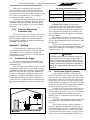
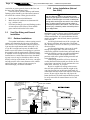
Section 3. Venting
The applicable codes, standards and Zodiac,
require that the heater be properly vented as outlined
in this manual. Proper ventilation of exhaust and
combustion air are essential for the safe and efficient
operation of the heater.
3.1
Combustion Air Supply
The heater location must provide sufficient air
supply for proper combustion and ventilation of the
surrounding area.
In general, the room in which a heater is installed
should be provided with two (2) permanent air supply
openings; one within 305 mm of the ceiling, the other
within 305 mm of the floor. All indoor installations
must have uninterrupted openings to outside air for
combustion, ventilation, and dilution of flue gases
from inside the building (see Figure 4 and Table 4).
Zodiac, does not recommend indoor installations that
do not provide combustion air from outside the building.
2m
2m
Figure 3.Outdoor Heater Installation
2m
ENGLISH
Page 11
Table 4. Ventilation Requirements
Positions of Air Vents
Air Vent Areas
(Air Direct From Outside)
High Level
270 cm2 plus 2.25 cm2 per kW in
excess of 60 kW total rated input
Low Level
540 cm2 plus 4.5 cm2 per kW in
excess of 60 kW total rated input
Exhaust Fans or Vents: Any equipment
which exhausts air from the room where the heater
is installed can deplete the combustion air supply or
reverse the natural draft action of the venting system.
This could cause flue products to accumulate in the
room. Additional air must be supplied to compensate
for such exhaust.
The information in Table 3 is not applicable in
installations where exhaust fans or blowers of any type
are used. Such installations must be designed by qualified engineers.
The heater must be completely isolated and
protected from any source of corrosive chemical fumes
such as those emitted by trichlorethylene, perchloroethylene, chlorine, etc.
WARNING
Do not store any chemicals, cleaners, or other corrosive material near combustion air openings or in
the room. Avoid locating appliance vents in the vicinity of combustion air openings. Failure to prevent
corrosive materials from mixing with combustion air
can result in reduced heater life and unsafe heater
operation.
3.2
Flue System Type B11 (Indoor)
Connect the draft diverter to a Type B11 flue
system of at least the same diameter, and end at least
0.6 meters above the highest point of the roof or other
object that is within 3.05 m of the vent. Install a certified terminal which allows a full equivalent opening
for flue products (see Figure 4). There must be at least
600 mm of vertical flue above the drafthood. Bends in
the flue should not exceed 45° to the vertical.
To make sure the heater operates safely and satisfactorily, the flue system must be able to completely
remove combustion products at all times. The number
of bends and lengths of horizontal flue pipe used
should be kept to a minimum in order to reduce gas
flow resistance.
Compliance with all national and local applicable
installation codes and regulations should be strictly
observed.
The flue design should avoid the formation of
excessive quantities of condensate. For this reason, it
is recommended that all flues be insulated and lined.
For brick or similar structures, a stainless steel rigid
or flexible flue liner (Grade 304/316) may be used in
conjunction with a 50 mm (minimum) thick layer or
Page 12
ENGLISH
Legacy™ Model LRZM Pool/Spa Heater | Installation and Operation Manual
vermiculite or perlite granules between the liner and
the inner skin of the chimney body.
Liners should be sealed at both top and bottom.
Drainage points should be provided at the bottom of
all vertical flue sections. Drain pipes should be:
1. No less than 25 mm inside diameter.
2. Made from acid condensate resistant material
(e.g., stainless steel).
3. Positioned so that pipe runs and discharge points
are not subject to the effects of frost and flue
gases cannot leak into the boiler room.
3.3
Vent Pipe Sizing and General
Installation
3.3.1Outdoor Installations
For outdoor installations, exhaust venting considerations will determine the placement of the heater
(See Section 2.5.4). If the heater cannot be placed so
as to meet the requirements stated in Section 2.5.4,
a Type B11 vent pipe and cap may be added to the
heater to move the exhaust vent opening to a position
that complies with the requirements. When the heater
is installed in areas of high wind or when unavoidably
installed near a vertical obstruction where downdrafting may occur, it may be desirable to add a vent cap
directly to the top of the heater. In all cases, vent pipes
and caps must be of the same diameter as the exhaust
outlet of the heater. Approved vent caps may be
obtained through your Zodiac distributor.
3.3.2Indoor Installations (Natural
Gas ONLY)
WARNING
Vent pipe diameter must be as required by applicable local gas appliance installation codes such as
BS 5440. Undersized pipe can result in inadequate
venting and oversize pipe can result in vent condensation. In either case the result can be release of
combustion products to the indoors. This can cause
serious injury or death by carbon monoxide poisoning or asphyxiation.
All indoor installations and outdoor shelter
installations require a factory approved draft hood and
Type B11 venting. The draft hood must be installed
without modification. All vent installations must be
made in accordance with all local, state or provincial
codes and with:
Avoid long horizontal runs of the vent pipe, and
90° elbows, reductions and restrictions. Horizontal
runs should have at least a 20 mm rise per meter in the
direction of flow.
Avoid terminating heater vents near air conditioning or air supply fans. The fans can pick up
exhaust flue products from the heater and return them
inside the building, creating a possible health hazard.
Do not locate the vent terminal where flue
products could strike against building materials and
cause degradation.
Vent opening should be well away from trees
or other obstructions that would prevent free air flow
to and from vent terminal. Do not terminate the vent
under decks, stairways, or car ports.
Be sure to support all venting so that connections will not separate and so that the weight of the
vent pipe does not rest on the heater draft hood. All
connections should be made with rustproof sheet metal
screws. Do not weld or fasten the vent pipe to the
heater draft hood. The draft hood and heater top must
be easily removable for normal heater service and
inspection.
3.1 m
VENT TERMINATED
AT LEAST 600 mm
ABOVE ANY OBJECT
WITHIN 3.1 m
LISTED FLUE TERMINAL
6.35 mm
minimum pitch
per meter
of horizontal
pipe
NOTE
Use approved
roof jack.
AT LEAST
600 mm OF
VERTICAL
FLUE ABOVE
THE DRAFT
HOOD
BENDS
SHOULD NOT
EXCEED 45°
DRAFT HOOD
NON-COMBUSTIBLE
BASE
Figure 4.Indoor Installation Venting or Outdoor Shelter Venting
4)
ENGLISH
Installation and Operation Manual | Legacy™ Model LRZM Pool/Spa Heater
The draft hood outlet is to be connected to an
unobstructed vent pipe of the same diameter, terminating outside the building. The vent must terminate at
least 0.6 m above the highest point of the roof or other
object that is within 3.05 m of the vent termination.
The vent pipe must have a listed vent cap which allows
a full equivalent opening for flue products (see Figure
4). The top of the vent cap must be at least five (5) feet
in vertical height above the draft hood outlet.
Double wall or equivalent vent pipe is recommended.
such as "The Gas Safety (Installation and Use)
Regulations" (Statutory Instrument 1998 No.
2451).
2.
Check the gas supply to be sure that it is the same
as the gas indicated on the heater's rating plate.
3.
If there is any doubt regarding the capacity of
any existing service pipes or the size required
for new service pipes then the advice of the
gas supplier should be requested. Installation
pipework should be fitted and tested for gas
soundness. Zodiac recommends the gas inlet pipe
sizes listed in Table 5.
4.
Use the figures in Table 5 to size the gas inlet
piping from the gas meter to the heater. Check all
local codes for compliance before installing the
heater.
IMPORTANT NOTE: Do not use sheet metal screws at
the snap lock joints of gas vents.
When venting multiple appliances through one
common duct, each appliance must have its own vent
temperature limit switch. All vent limit switches must
be wired in series so as to prevent any appliance from
firing in the event of a blocked vent. Refer to national
and local installation codes for more information on
multiple venting.
3.3.3Inspection and Replacement of
Existing Vent System with New
Components If the Legacy heater is being installed to replace
an existing pool heater, it is recommended that a new
appropriate venting system be installed with the new
heater. However, if an existing venting system must be
used, be sure to carefully inspect the venting system to
ensure that it is in good condition and continues to be
appropriate for the Legacy heater. Replace any parts
that are not in good and serviceable condition with
new parts before completing the pool heater installation.
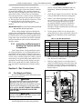
Section 4. Gas Connections
4.1
Table 5. Pipe Size Requirements*
Distance from Gas Meter
Heater
Size
0-15 m
15-30 m
30-60 m
mm
mm
mm
125
20
25
25
175
25
25
32
250
25
32
32
325
32
32
40
400
32
40
40
5.
Before operating the heater, test for gas soundness. Do not use a naked flame.
6.
If the gas supply pressure is less than required,
check for undersized pipe between the meter and
the heater, a restrictive fitting, or an undersized
gas meter. Gas supply pressures to the heater are
listed in Table 2.
Gas Supply and Piping
Review the following general instructions before
continuing the installation.
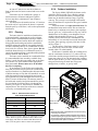
WARNING
The Legacy Model LRZ pool and spa heaters are
designed for use with either natural gas or LPG.
Check the rating plate on the inner panel to be sure
that the heater is designed to use the type of gas
being supplied. DO NOT ATTEMPT TO CONVERT
THIS HEATER FOR USE WITH ANY OTHER
TYPE OF FUEL.
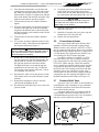
CAUTION
Inlet Gas Pressure
Test Port
Gas Cock
Burner Pressure
Point
Permanent damage to the gas valve will occur if the
following procedures are not followed.
1.
Gas piping installation must be in accordance
with all applicable local rules and regulations
Page 13
Figure 5.
Fitting a Gas Service Cock
Page 14
4.2
ENGLISH
Legacy™ Model LRZM Pool/Spa Heater | Installation and Operation Manual
Burner Pressure
Confirm that gas supply pressure is correct. If
the gas supply pressure is less than required, check for
undersized pipe between the meter and the heater, a
restrictive fitting, or an undersized gas meter. Gas inlet
pressures to the heater, when it is operating, are listed
in Table 2.
CAUTION
Burner gas pressure for the Legacy Model LRZ
natural gas heaters should be set to the values
listed in Table 2.
The burner pressure may be checked by connecting a manometer to the pressure port on the burner.
Refer to Figure 5. The pressure will be zero when the
heater is not running. When the heater is operating the
burner gas pressure should be the values listed in
Table 2.
If the burner pressure indicated above is not
correct, check the gas train for possible problems.
Check the meter, gas line, gas fittings, and gas shut off
for under sizing. Check the gas valve inlet for excess
pipe dope, if all is correct, then it may be necessary to
adjust the gas valve regulator. To adjust the burner gas
pressure, first remove the slotted cap next to the inlet
pressure port on the inlet side of the gas valve. Under
the slotted cap is a slotted plastic screw which increases the burner pressure when turned clockwise and
decreases the burner pressure when turned counterclockwise. After measurements, and adjustments if
necessary, have been made, make sure to replace the
test point plugs on the inlet and burner pressure ports,
and the cap on the burner pressure adjustment screw.
It is extremely important to replace these parts before
leaving the installation. Failure to do so can result in
damage to property or injury or death. With the heater
firing, the pressure must be within the range shown in
Table 2. Also check the pressure with the heater off.
4.3Special Precautions for LPG
LPG is heavier than air and can therefore more
readily collect or “pool” in enclosed areas if provision
for proper ventilation is not made. Installation of pool
heaters in enclosed areas such as pits is not recommended.
Consult any local code and fire protection authorities about specific installation restrictions in your area.
Section 5. Water Connections
5.1
Water Piping
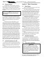
5.2
Hydraulic Head Loss
5.3
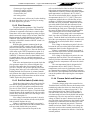
Check Valve Installation
Figure 6 illustrates typical piping for pool equipment in pool/spa combination pools.
For normal installations, do not install a shutoff
valve or any kind of variable restriction in the water
piping between the heater outlet and the pool/spa. In
special installations where a shut-off valve, diverter
valve or other variable restriction is required in the
plumbing between the heater outlet and the pool,
Zodiac recommends the installation of a pressure relief
valve on the heater (see Section 5.7).
Arrangement of pool system components other
than as illustrated in these diagrams can affect the
operation of the heater’s water pressure switch.
Location of the heater above or below the pool water
surface can also affect operation of the switch. In
general, the pressure switch can be adjusted to accommodate this effect if the heater water connections
are no more than 1.8 m below the pool water surface
and no more than 4.5 m above it. See instructions for
pressure switch adjustment (Section 5.7) in the heater
start-up section of this manual for more information
about this.
Note that when pool equipment is located below
the pool surface a leak can result in large scale water
loss or flooding. Zodiac cannot be responsible for such
water loss or flooding or the damage caused by either
occurrence.
For special installations such as water connections below the water level of the pool, or for other
questions consult your local Zodiac dealer.
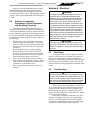
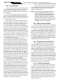
To verify that the minimum flows required
for the heater are met, a hydraulic head loss curve
is shown in Figure 7. This should be checked when
installing this heater into a new or existing piping
system. This should also be consulted when installing
a new pump.
WARNING
A check valve can interfere with the proper
operation of certain Suction Vacuum Release
System (SVRS) products. To avoid possible entrapment hazard, serious injury, or death, make
sure to review the operation/owners manual of
your particular SVRS product before installing
the check valve.
The heater must be protected from back-siphoning of water, which can result in dry starts. If there is
any chance of back-siphoning, provide a check valve
between the pool and the filter pump inlet.
ENGLISH
Installation and Operation Manual | Legacy™ Model LRZM Pool/Spa Heater
Page 15
AQUAPURE
MANUAL BY-PASS DETAIL
MANUAL BY-PASS IS USED
WHEN FILTRATION RATE
EXCEEDS 125 GPM
Figure 6.Typical Piping Installation
LRZ Pressure Drop vs Flow
5
4.5
LRZ400
Pressure Drop (m H2O)
4
LRZ325
LRZ175
3.5
LRZ250
LRZ125
3
2.5
2
1.5
1
0.5
0
0
100
200
300
400
500
Water Flow (LPM)
Figure 7.
Hydraulic Head Loss Curve
When an automatic chemical feeder is installed
in the plumbing, it must be installed downstream of
the heater (see Section 5.7). A check valve must be
installed between the heater and the chemical feeder to
prevent back-siphoning of chemically saturated water
into the heater where it will damage the components.
5.4Automatic Flow Control Valve
The inlet/outlet header of the Legacy Model LRZ
millivolt heater comes equipped with an automatic
flow control valve. The automatic flow control valve
maintains the proper flow through the heater at rates
up to approximately 475 lpm. If the filter system flow
rate is higher than approximately 475 lpm, install a
manual bypass valve (see Figure 6), then perform a
temperature rise test (see Section 11.6) and adjust the
flow using the bypass valve until the proper temperature rise is obtained.
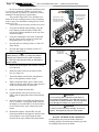
5.5Reversible Water Connections
The Legacy Model LRZ millivolt heater is
shipped with water connections on the right side,
but can be modified in the field to provide left-side
water connections. This procedure involves removing the heat exchanger headers and reinstalling them
on opposite ends of the tube assembly. Some of the
heater wiring must be disconnected and re-routed, so
this procedure must be done only by a trained service
technician. Heat exchanger reversals are generally
done before the installation of power and water to the
heater. If you need to reverse the heat exchanger on
a previously installed heater be sure that all electrical power, the gas supply and water supply have been
turned off before starting the procedure. These instructions have been written to include the steps needed
when reversing the water connections on an existing
installation. If you are reversing the headers on a new
installation, some steps will be ignored.
Page 16
ENGLISH
Legacy™ Model LRZM Pool/Spa Heater | Installation and Operation Manual
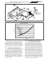
Water connection reversal is illustrated in Figures
8 and 9. Proceed as follows:
1.
For an existing installation, drain the heater by
removing the two (2) drain plugs on the inlet/
outlet header and the drain plug on the return
header.
2.
Remove the heater front panel (door).
3.
Remove the I/O header side cover plates, top and
bottom. See Figure 10.
4.
Remove the return header side cover plates, top
and bottom. See Figure 10.
5.
Tag and disconnect the black high limit wire
leading to the pressure switch (PS) and the black
wire on the Fireman's switch terminal which
leads to the high limit switch.
6.
Remove the water temperature sensor nut from
the inlet/outlet header and remove the sensor.
7.
Tag and disconnect the black and white wires
from the water pressure switch.
CAUTION
In order to prevent property damage or injury, ensure that the wiring is handled and routed carefully
so as not to cause any damage to it. Additionally, be
careful not to create any kinks in the water pressure
switch copper tubing when handling the header.
8.
For an existing installation, remove the coupling
nuts from the header and disconnect the water
supply from the heater.
9. Remove the 10 bolts and washers from the inlet/
outlet header and remove the header from the
tube assembly.
10. Remove the 10 bolts and washers from the return
header and remove the header from the tube
assembly.
11. For an existing installation, remove the tube
gaskets and clean the header's mating surface of
any corrosion or debris. Replace the tube gaskets
with new ones. Do not use any metal tools on the
header surface. Scratches may compromise the
seal integrity.
WARNING
To avoid product failure which can cause property
damage, serious personal injury or death, install the
inlet/outlet header with the high limit devices on the
bottom.
VENT TOP
RETURN HEADER SIDE
COVER PLATES
TOP AND BOTTOM
LEFT SIDE PANEL
Figure 8. Water Connections as Shipped
DO NOT
INTALL THE
INLET/OUTLET
HEADER
UPSIDE-DOWN
Figure 9.
REAR PANEL
®
THE HIGH LIMIT
DEVICES MUST
BE ON THE
BOTTOM
NOTE: When reversal
is complete the water
temperature sensor
wires and the syphon
loop tube will exit the
inlet/outlet header at
the back of the heater
and the drain plugs are
facing down.
TOP PANEL
CONTROL PANEL
BASE
IN/OUT HEADER
SIDE COVER PLATES
TOP AND BOTTOM
FRONT PANEL
(DOOR)
RIGHT SIDE PANEL
Bypass
Assembly
Water Connections Reversed
Figure 10.Legacy Panel Identification
Installation and Operation Manual | Legacy™ Model LRZM Pool/Spa Heater
12. Place the inlet/outlet header over the bolts and
gasketed tubes on the left side of the tube assembly. Make sure the high limit devices are on the
bottom. Refer to Figure 9. Align the bolt and tube
holes in the header with the bolts and tubes in the
header bar and slide the assembly together.
13. Thread on the 10 bolts and washers and hand
tighten.
14. Place the return header over the bolts and gasketed tubes on the right side of the tube assembly.
Align the bolt and tube holes in the header with
the bolts and tubes in the header bar and slide the
assembly together.
15. Thread on the 10 bolts and washers and hand
tighten.
16. Use a torque wrench to tighten the bolts on each
header to 4 ft-lbs. The bolts must be tightened in
the sequence indicated in Figure 11.
CAUTION
Failure to tighten the header as indicated in step 16
may cause the header to leak or become permanently damaged from warping.
17. Remove the 3/4 inch button plug located in the
left side panel below the inlet/outlet header and
replace with the 3/4 inch wire grommet from
the right side panel below the return header.
The high limit leads were routed through this
grommet prior to removal in step 5. Install the
3/4 inch plug in the opening where the 3/4 inch
wire grommet was removed.
18. Reconnect the white wire on the pressure switch
(PS) and the white wire on the Fireman's switch
terminal.
19. Reinstall the temperature sensor in the inlet/
outlet header and tighten the nut.
20. Reconnect the black and white wires to the water
pressure switch.
ENGLISH
Page 17
21. Use plastic wire ties to refasten the temperature
sensor, high limit switch and water pressure
switch wires to each other. Bundle the wires near
the control panel and fasten them with a wire tie.
CAUTION
In order to prevent property damage or injury, be
sure that none of the wires are in contact with a
sharp edge or a hot surface.
22. Install the return header side cover plate on the
right side of the unit.
23. Install the I/O header side cover plates, top and
bottom on the left side of the unit.
24. Replace the front panel (door).
5.6
Connections at Heater
The Legacy Model LRZ millivolt heater has a
standard 2 inch water header and coupling design.
With this feature, only nominal 2 inch PVC or CPVC
may be connected to the heater. However, by installing
the appropriate pipe adapters and two (2) short pieces
of 2 inch plastic pipe (supplied by the installer), any
size existing pipe may be fitted to the heater.
To connect a section of 2 inch PVC or CPVC
pipe to the heater, first slip a coupling nut onto the
pipe. Then prepare the end of the pipe with the proper
PVC/CPVC primer and glue. Follow the manufacturer’s instructions provided with the primer and glue
for preparation procedures and curing times. Apply
the slip-fit side of the coupling to the end of the pipe.
Allow the glue to cure completely. Set the o-ring
into the groove on the face of the coupling. Slide the
coupling nut up to the coupling and tighten it to the
threaded connection on the header (see Figure 12).
5.7Pressure Relief Valve
A pressure relief valve (PRV) is recommended in
all installations, and is mandatory in any installation
in which the water flow can be shut off between the
heater outlet and the pool/spa.
A pressure relief valve is not supplied with the
Legacy Model LRZ millivolt heater. However, it is
recommended that a pressure relief valve be installed
and may even be required by local codes.
PVC OR CPVC PIPE
7
8
O-RING
3
4
2
1
6
5
9
10
Figure 11. Header Bolt Tightening Sequence
COUPLING
COUPLING
NUT
Figure 12.Piping to Heater
page 18
enGlisH
Legacy™ Model LRZM Pool/Spa Heater | Installation and Operation Manual
Be sure to check any applicable installation codes
in your area to determine whether a pressure relief
valve is required. See Section 12.2 (Parts List) of this
manual for the appropriate kit part number.
The pressure rating of the valve should be at or
below the lowest working pressure of any component
in the system. The maximum working pressure of this
heater is 5.1 bar.
Follow these steps to install a pressure relief valve:
1. To protect the threads while drilling, screw the
brass adapter (included with the Zodiac PRV
kit) into the blind threaded hole on the top of the
inlet/outlet header.
2. Using the countersink in the center of the blind
hole as a guide, drill a 6.4 mm (1/4 inch) hole
through the plastic (see Figure 13).
3. Open the hole by reaming it with a 9.5 mm (3/8
inch) drill bit.
4.
Open the hole again by reaming it with a 12.7
mm (1/2 inch) drill bit.
Caution
Initially drilling a 12.7 mm (1/2 inch) hole without
reaming may cause the bit to "grab" on the plastic. This may cause personal injury or damage the
plastic header.
5.
Remove the brass adapter and clean the cuttings
out of the hole.
6.
Install the rubber washer at the bottom of the
hole (see Figure 14).
7.
Thread the adapter into the hole and tighten so
that it seals against the rubber washer.
8.
With a permanent marker, place a mark on the
adapter so that the mark faces the same direction
as the water connections on the header.
9.
Remove the adapter from the hole.
10. Coat the threads of the pressure relief valve
(PRV) with an appropriate metal to metal thread
sealant.
11. Install the adapter on the PRV and tighten using
two (2) wrenches. Use the mark made earlier on
the adapter to orient the PRV to the desired direction in relation to the water connections on the
header.
12. Reinstall the adapter, with the PRV, into the
plastic threaded hole and tighten it until the mark
on the adapter is once again facing the same
direction as the water connections on the header.
START WITH A 1/4" BIT
THEN OPEN HOLE WITH
A 3/8" BIT THEN OPEN
HOLE WITH A 1/2" BIT
TEMPORARILY INSTALL
BRASS ADAPTER TO
PROTECT PLASTIC
THREADS
Figure 13. drill Hole for pressure relief Valve
PRESSURE RELIEF
VALVE HAND
TIGHTEN ONLY
RUBBER WASHER
BRASS ADAPTER
Figure 14. pressure relief Valve installation
Caution
Do not use any pipe compound or pipe dope on
the threads of the adapter or any part that comes in
contact with the plastic headers. These compounds
may damage the header over a period of time.
Caution
In order to prevent property damage, do not overtighten. Overtightening may crack the header.
DO NOT TIGHTEN WITH A WRENCH.
Overtightening may crack the header. Route the
discharge piping so that discharge from the pipe does
not endanger anyone near the heater.
Installation and Operation Manual | Legacy™ Model LRZM Pool/Spa Heater
Refer to your local installation codes for more
detailed information. The valve setting should be
at or below the maximum working pressure of any
component in the filter system. The maximum working
pressure of the Legacy Model LRZ millivolt heater is
5.1 bar.
5.8Auxiliary Components,
Chlorinators, Ozone Generators,
and Sanitizing Chemicals
The Legacy Model LRZ millivolt heater is
manufactured with materials that are not compatible
with high concentrations of ozone, chlorine, bromine,
or other sanitizing chemicals. Heater damage caused
by excessive chemicals or improper ozonization is not
covered by the Zodiac warranty. Be sure to adhere to
the following:
•
When ozone is injected upstream of the heater,
install an offgas mixing chamber, or an ozone
bypass system between the heater and the ozone
injector to prevent ozone and air from entering
the heater.
•
When chemical feeders are used, plumb the
feeder downstream of the heater and install
an in-line check valve between the heater and
the feeder (a minimum of 450 mm is required
between the heater and the check valve).
•
Wire any electrical chemical feeder so that it
cannot operate unless the filter pump is running.
If the feeder has an independent clock control,
synchronize it with the filter clock.
•
Never deposit chemicals directly in the pool
skimmer.
ENGLISH
Page 19
Section 6. Electrical
WARNING
This product must be installed and serviced by a
contractor who is licensed and qualified in pool
equipment by the jurisdiction in which the product
will be installed where such state or local requirements exists. In the event no such state or local
requirement exists, the installer or maintainer must
be a professional with sufficient experience in pool
equipment installation and maintenance so that all
of the instructions in this manual can be followed
exactly. Before installing this product, read and follow all warning notices and instructions that accompany this product. Failure to follow warning notices
and instructions may result in property damage,
personal injury, or death.
CAUTION
Label all wires prior to disconnection when servicing controls. Wiring errors can cause improper and
dangerous operation. Verify proper operation after
servicing.
6.1
Main Power
The Legacy heater does not require an external
source of electrical power to operate. The power for
the gas valve and safety circuit are generated by a
thermopile. The thermopile generates a millivolt signal
when heated by the pilot flame. Figure 15 shows the
internal electrical wiring diagram and schematic of the
heater.
6.2Earth Bonding
CAUTION
To prevent premature failure of the appliance resulting from stray voltages and voltage differentials, the
heater must be bonded to other equipment which is
part of the pool plumbing system with a solid copper
wire not smaller in diameter than 8 AWG (10mm2).
Zodiac requires that the appliance be connected
to an "earth bonding loop" that includes all electrical
equipment in the system and on the equipment pad.
Earth bonding lugs must be connected with a solid
copper wire not smaller than 8 AWG (10mm2). Failure
to do so will void warranty.
Additionally, all metallic components of a pool
structure, including reinforcing steel, metal fittings
and above ground components be bonded together
(forming an “earth bonding grid”) with a solid copper
conductor not smaller than a 8 AWG (10mm2).
Page 20
ENGLISH
TH
Legacy™ Model LRZM Pool/Spa Heater | Installation and Operation Manual
TEMPERATURE
CONTROL
BK
BK
TP
R
BK
W
TP/TH
GAS VALVE
W
W
W
W
EARTH
BONDING
LUG
PILOT
GENERATOR
PILOT
BK
BK
W
ROLL-OUT SWITCH
(FUSIBLE LINK)
W
240°C (464°F)
VENT
TEMPERATURE
LIMIT
PRESSURE
SWITCH
HIGH
LIMIT
HIGH
LIMIT
W
BK
BK
42°C
(108°F)
52°C
(126°F)
FIREMAN
SWITCH
IGNITER
®
R
W
BK - BLACK
R - RED
W - WHITE
R
H0321000 Rev E
Figure 15.Legacy Wiring Diagram
The equipment and/or appliances associated
with the pool water circulating system, including, but
not limited to, pump motors and heaters must also be
bonded together as part of the equipotential bonding
grid. Zodiac provides a special labeled earth bonding
lug on the right side of the heater to accommodate this
requirement. Consult your local applicable installation
codes/regulations for additional requirements that may
apply.
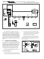
3.
Connect the wires from the time clock auxiliary
switch to the two (2) terminals. Use 14 AWG (2,5
mm2) stranded copper wire with a temperature
rating of 105°C (221°F) or greater.
The length of the wire between the heater and
the time clock should not exceed 4.57 m. The contact
points of the time clock switch should be silver, or a
low resistance alloy.
6.3Auxiliary Time Clock Wiring
If you install a time clock to control the filter
pump operation, it is recommended that the time clock
have its own low voltage (Fireman’s) switch to turn
off the heater before turning off the pump. The switch
should shut off the heater about 15 minutes before
the filter pump shuts off. This will allow for a more
efficient operation by removing any residual heat
contained in the heat exchanger back to the pool.
To install a time clock auxiliary switch into the
heater wires (see Figure 16):
1. Remove heater door.
2. Remove the factory installed wire between terminals 1 and 2 on the terminal strip (see Figure 16).
BLACK
BLACK
OR CONTROL
ROLL-OUT SWITCH
(VENT FUSIBLE LINK)
VENT TEMPERATURE LIMIT
Figure 16.Time Clock Wiring or Control Connection
Installation and Operation Manual | Legacy™ Model LRZM Pool/Spa Heater
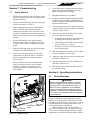
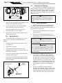
Section 7. Commissioning
7.1
1.
2.
Check the manifold (burner) pressure setting and
adjust as necessary (see Table 1).
3.
Start the adjustment procedure with the heater
cold, on full load, and with the temperature
control set at maximum. This will ensure, as far
as possible, that thermostatic shutdown does not
interfere while the pressure is being checked and
adjusted.
4.
Remove the blanking screw in the manifold
(burner) setting pressure test nipple (see Figure
17) and securely connect a suitable gas pressure
gauge.
5.
Light the heater and allow it to operate for about
15 minutes to stabilize the burners.
6.
Check the pressure and adjust it for the appropriate heater size. Refer to Table 2. The burner
pressure setting adjuster is found on the gas
control (valve).
7.
Remove the dust cover over the adjuster and,
using a screwdriver, turn the screw beneath
clockwise to increase or anti-clockwise to
decrease the pressure. Replace the dust cover
when finished.
Page 21
8.
Turn off the burner, disconnect the gas pressure
gauge, and replace the blanking screw in the
burner setting pressure test nipple.
9
Relight and check for gas soundness.
Heater Start-Up
When the heater has lit, remove the service door
and check all gas connections for soundness with
leak detection fluid.
ENGLISH
10. For heaters installed with a draft hood, perform
a spillage test in accordance with BS.5440:1 to
check for spillage of combustion products from
the heater draft diverter.
11. Check that the main burner responds correctly to
manual ON/OFF operations of any controls fitted
in the gas control circuit.
12. Check the operation of the flame failure safety
device using the following steps:
a. Extinguish the main burner and pilot burner
by turning off the main gas inlet cock.
b. Check that the flame failure device is heard
to close within one (1) minute.
c. Wait three (3) minutes, then turn on the gas
and re-light the pilot.
13. With the pump running, check for water leaks in
the heat exchanger or water piping.
14 Adjust the water pressure switch according to the
procedure in Section 11.5.
15. Perform a temperature rise test acording to the
procedure in Section 11.6.
16. Refit the service door and return all controls to
the required settings.
Section 8. Operating Instructions
8.1Normal Operation
WARNING
Improper installation or maintenance can cause
nausea or asphyxiation from carbon monoxide in
flue gases which could result in severe injury, or
death. For indoor installations, as an additional
measure of safety, Zodiac strongly recommends
installation of suitable Carbon Monoxide detectors
in the vicinity of this appliance and in any adjacent
occupied spaces.
Pressure Test Nipple
with Blanking Screw
Burner Pressure
Inlet Gas Pressure Adjustment
Test Point
Figure 17.Lighting the Pilot
The Legacy model LRZ millivolt heaters are
capable of automatic operation based on a call for
heat at a preset temperature. The heater has an internal safety system which allows operation in a variety
of conditions and prevents operation when certain
adverse conditions are encountered.
When the heater's pilot is lit and the pilot
generator is providing a millivolt signal to the safety
circuit, water is flowing through the heater, and the
temperature of the water entering the heater is below
Page 22
ENGLISH
Legacy™ Model LRZM Pool/Spa Heater | Installation and Operation Manual
the temperature control setting, an operating cycle is
initiated by the automatic control. The temperature
control circuit is closed, activating the gas valve and
the gas valve is opened. Gas flows through the burners,
is mixed with air in the combustion chamber, and is
ignited by the pilot. Operation will continue until the
temperature of the water entering the heater reaches
the temperature control setting.
If ignition is unsuccessful, or if the flame fails
during normal operation, the temperature control
circuit opens and shuts off the gas valve.
8.2Start-Up
Caution
Do not use this heater if any part has been under
water. Immediately call a qualified service technician to inspect the heater and replace any part of
the control system and any gas control which has
been under water.
Caution
Should overheating occur or the gas supply fail to
shut off, turn off the manual gas control valve to the
heater.
CAUTION
Do not attempt repairs on the gas controls or appliance. Tampering is dangerous and voids all warranties.
Caution
Keep all objects off the top of the heater. Blocking
air flow could damage the heater, and may void the
warranty.
WARNING
Vent pipes, draft hoods, and heater tops get hot!
These surfaces can cause serious burns. Do not
touch these surfaces while the heater is in operation. Adding a vent cap reduces the temperature on
the top.
WARNING
For your safety, when starting the heater, keep your
head and face well away from the lower firebox
opening to prevent any risk of personal injury.
Be sure that there is water in the pool and that the
surface level is above the skimmer or other inlet of the
pool’s filter system.
Confirm that pool water is flowing normally
through the pool system and equipment. With any
new pool or spa installation, operate the filter pump
with the heater off long enough to completely clean
the water. This will remove any installation residue
from the water. Clean the filter at the end of this
operation before starting the heater. Start the heater
in accordance with the Operating Instructions section
of this manual, with particular attention to the lighting and shutdown instructions and temperature control
operation.
The heater may not start on the first try. Air in
the gas line or other start-up situations may cause it to
cycle.
When raising the temperature of a cold pool,
remove all time clock settings. This lets the filter
system and heater operate continuously until the water
reaches the temperature setting on the temperature
control. When that happens, the heater will automatically shut off, but the filter pump will keep running.
When the heater starts, immediately feel the
outlet header of the heater to confirm that there is
adequate water flow. The header should not be hot.
Normally, water temperature will rise only a few
degrees as it passes through the heater, and a “hot”
header or pipe indicates low water flow.
WARNING
When the heater is fired for the first time, the combustion chamber refractory binder material is driven
out by the heat of the flame. White smoke and/or
sharp odors may be emitted from the vent during
this period. Do not inhale combustion product fumes
at any time, and especially when these fumes are
being emitted. This "burn-in" period will last only a
few minutes.
8.3Lighting and Shutdown Procedures
Before starting your heater, be sure that you are
familiar with the setting and operation of the heater
controls. Once the controls are set to your preferences,
follow the instructions outlined on the following page.
Read and follow all safety instructions first.
A more detailed set of instructions of the operation of the controller follows in the next section.
NOTE If your heater is configured to operate on LPG
and the LPG tank runs out of fuel, turn off
gas at the heater. After the tank is refilled, the
heater must be relit following the instructions
found on the inside of the heater. A copy of
these instructions appears on the following
page.
WARNING
DO NOT attempt repairs on the gas control or
heater. Tampering can cause severe bodily injury or
death and voids all warranties.
WARNING
Do not attempt to operate the heater with the door
off. Doing so may cause severe bodily injury.
8.3.1Lighting the Heater
Full lighting and shutdown instructions can
also be found attached to the wall inside the control
compartment door. See Figure 18.
1. Remove the service door on the front of the
heater.
ENGLISH
Installation and Operation Manual | Legacy™ Model LRZM Pool/Spa Heater
WARNING
LP Gas Models: To avoid possible injury, fire and
explosion, read and follow these precautions and
all instructions on this appliance before starting the
heater. LP (propane) gas is heavier than air and
will remain at ground level if there is a leak. Before
lighting, sniff at ground level. If you smell gas, follow
these rules:
1. DO NOT light matches. DO NOT turn electric
lights or switches on or off in area. DO NOT use
an electric fan to remove the gas from area.
2. Shut off gas at LP tank.
3. Telephone gas company and fire department
for instructions. Give your name, address and
phone number.
If your LP tank runs out of fuel, turn off gas at the
appliance. After the tank is refilled, the appliance
must be re-started according to the instructions
located on the inside of the door.
WARNING
Natural Gas Models: To avoid possible injury, fire
and explosion, read and follow these precautions
and all instructions on this heater before lighting the
pilot. If you smell gas, follow these rules:
1. DO NOT light matches. DO NOT turn electric
lights or switches on or off in area. DO NOT use
an electric fan to remove the gas from area.
2. Shut off gas at gas service cock.
3. Telephone gas company and fire department
for instructions. Give your name, address and
phone number.
DO NOT attempt repairs on the gas control or
heater. Tampering is dangerous and voids all warranties. Page 23
For Your saFetY read
BeFore operatinG
WarninG: if you do not follow these instructions
exactly, a fire or explosion may result, causing property damage, personal injury or loss of life.
liGHtinG instruCtions
insTRUCTiOns TO lighT hEATER
1. Position On/OFF switch to “OFF”.
2. Turn gas control knob clockwise
until it stops at
“
” (OFF) position.
3. Wait five (5) minutes before lighting pilot.
4. Turn knob on gas valve counterclockwise
to
“ ” (PilOT) then push control knob all the way and
hold down. Push the button of the sparker, repeating
until confirming that pilot lights, by observing reflection
on burner tray mirror. Continue to hold the control knob
in for about one (1) minute after the pilot is lit. if it goes
out, repeat steps 3 and 4.
5. Turn gas control knob counterclockwise
to “ ”
(On).
6. After replacing door, set thermostat to desired setting
and turn appliance On/OFF switch to “On”. Valve has
built-in delay before coming on.
RElighTing
if pilot goes out, repeat steps 1 through 6.
TO shUT OFF hEATER
To shut off main burners turn gas control knob
clockwise
until it stops at “ ” (PilOT). For
complete shut-off press down slightly on knob while
turning clockwise
to “
” (OFF). Do not force.
Position On/OFF switch to “OFF”.
Control Knob
with OFF, Pilot
and ON Position
Pilot Adjustment
Regulator
iMportant inForMation
1. CAUTiOn: Do not store pool chemicals or flammable
materials near this appliance.
2. Ph lEVEl: Pool Water must be maintained between 7.4
and 7.6 when operating unit (see section entitled "Water
Chemistry" in operating manual).
3. BACKWAshing: Turn heater off 20 minutes before
backwashing or shutting down filter to prevent damage
to unit.
4. WinTERiZE: All gas to unit must be shut off and all water
drained from unit to protect it from freezing damage.
nOTE: This DOOR MUsT BE FiTTED TO UniT DURing
nORMAl OPERATiOns.
For Your saFetY
DO nOT sTORE OR UsE gAsOlinE OR OThER
FlAMMABlE VAPORs OR liQUiDs in ThE ViCiniTY OF This
OR AnY OThER APPliAnCE.
nOTE: sOME EXPOsED PARTs OF This hEATER MAY BE
hOT WhEn OPERATing.
®
H0320600 Rev B
Figure 18.Legacy Lighting and Shutdown Procedures
Page 24
ENGLISH
Legacy™ Model LRZM Pool/Spa Heater | Installation and Operation Manual
8.3.2Relighting the Heater
Control Knob
with OFF, Pilot
and ON Position
Pilot Adjustment
If the pilot goes out, repeat steps 5 through 7 in
Section 8.3.1.
8.3.3Shut-Down Procedure
Regulator
Figure 19.Natural Gas/Propane Control Valve
2.
3.
4.
5.
6.
7.
8.
9.
Turn the gas control knob clockwise until it stops
at the OFF position (see Figure 19).
Wait five (5) minutes before lighting the pilot.
Turn the knob on the gas valve counterclockwise
to PILOT, then push the control knob all the way
and hold down. Push the button of the sparker,
repeating until confirming that the pilot lights by
observing the reflection on the burner tray mirror.
Continue to hold the control knob in for about
one (1) minute after the pilot is lit. If it goes out,
repeat Steps 3 and 4.
Release the control knob and verify that the pilot
is lit.
If the pilot burner does not remain lit when the
button is released, press and release the red
button. Wait at least three (3) minutes and then
repeat the lighting procedure from step 4.
If the pilot cannot be established, check that the
pilot burner flame correctly envelops the thermocouple tip by 10 to 13 mm. If not, check that the
pilot adjustment screw on the gas control (see
Figure 19) is fully unscrewed, then turn it one (1)
turn back in. Check that the thermocouple lead
connections at the gas control and at the overheat
thermostat are clean and secure. Repeat from
Step 4.
Turn gas valve knob to ON. Replace the service
door.
Turn the rocker switch to ON.
1.
To turn the main burner off, turn the rocker
switch to OFF.
2.
To turn the heater off (including the pilot), turn
the gas valve knob to the OFF position.
8.4Turning the Heater On/Off and
Setting the Temperature Control
The temperature control (see Figure 20) is
calibrated at the factory and covers a range from
approximately 21°C to 40°C (70°F to 104°F). Use an
accurate pool thermometer to determine the best water
temperature for your use.
The Legacy temperature control panel has a
rocker switch to turn the heater on and off. It also has
a rotary dial to set the desired thermostat setting (see
Figure 20).
Once the heater has been lit by following the
safety and lighting procedures in Section 8.3, set the
toggle switch on the control panel to "ON" to start the
heater operation. If the heater senses that the pump
is on and the thermostat setting is higher than the
temperature of the pool/spa water, the pilot will ignite
the main burners.
CAUTION
In order to prevent property damage, the heater is
designed to run only when the filter pump is running. If the heater does not immediately turn off
when the pump turns off, turn the heater off at the
control panel. The heater's pressure switch may
need adjusting (see Section 11.5)
10. Set temperature control to against the Temp-Lok
tab. The main burner should light. Until the water
reaches a temperature of about 21°C (70°F), it is
normal to have some water accumulating in the
base of the heater.
H0286600
11. Set the time clock, if one is installed.
Figure 20.Temperature Control
Installation and Operation Manual | Legacy™ Model LRZM Pool/Spa Heater
Once the pool/spa water temperature reaches the
thermostat setting, the heater will automatically stop
firing. As the pool/spa water temperature falls below
the thermostat setting the heater will once again start
the heating cycle.
Rotate the thermostat dial clockwise to increase
the temperature setting and counterclockwise to
decrease the setting. It may take several attempts to
set the thermostat dial to the desired temperature. Be
sure to use an accurate thermometer to measure water
temperature. Once the desired temperature setting is
found, loosen the screw on the Temp-Lok ring and
rotate the ring until the stop rests against the knob.
Tighten the screw to hold the knob in position. This
will prevent accidental moving of the dial and possible
overheating of the water.
IMPORTANT: The temperature controls cannot
be calibrated in the field. If the control is faulty,
shut down the heater by following the procedures in
Section 8.3 and have a qualified service technician
replace the control. DO NOT use the thermostat switch
to completely shut down the heater.
Section 9. Maintenance
9.1
Water Chemistry
The mineral content of swimming pool water
increases daily due to natural evaporation and the
addition of sanitizing chemicals. If the mineral concentration in the pool gets too high, the excess minerals will deposit on the walls of the pool, in the filter
system, and in the heater tubes.
The proper chemical balance in spa water is
more critical than in a swimming pool heater operation. Due to the spa's size, high water temperature and
heavy usage, chemical values in a spa can vary greatly.
This chemical imbalance can result in unsanitary water
conditions, and affect the life of the heater.
Proper chemical balances are necessary for
sanitary bathing conditions as well as ensuring your
heater's long life. Kits are available from your local
pool supply dealer for making the various tests for
mineral content. One of these kits will detect copper
in the system. This is usually a warning that corrosion is taking place, possibly due to a low pH value
combined with other chemistry problems. The condition can be corrected by changing the spa water and
closely monitoring the pH factor and chemical properties of the water. Be sure to keep your chemical levels
within the values indicated in Table 7. Zodiac does
not warrant heat exchangers damaged by corrosive
chemical levels or excess dissolved solids in pool or
spa water.
For spas, it is also necessary to perform water
changes in addition to chemical treatment. It is recommended to change the spa water every 60 days for light
usage and every 30 days if usage is heavy.
ENGLISH
Page 25
Table 7. Optimal Water Chemistry Ranges*
Test
Recommended Level
Free Chlorine
1.0 to 3.0 ppm
Bromine
2.0 to 4.0 ppm
pH
7.4 to 7.6
Total Alkalinity (TA)
80 to 120 ppm
Calcium Hardness (CH)
175 to 400 ppm
Cyanuric Acid
10 to 50 ppm
Total Dissolved Solids
(TDS)
1000 to 2000 ppm (Excluding dissolved NaCl from a Salt Chlorine
Generator)
Copper
0 ppm
* Concentration levels taken from "Basic Pool and Spa
Technology" published by APSP (Association of Pool and Spa
Professionals).
9.2Seasonal Care
CAUTION
Do not operate this heater outdoors at temperatures below 20 degrees Fahrenheit (°F) (-7 degrees
Celsius [°C]).
9.2.1Spring and Fall Operation
During periods when the pool is only going to be
used occasionally, turn the temperature control down
to the MIN setting. This prevents the pool water from
becoming chilled, and minimizes the time required to
raise the pool water back up to the desired temperature.
In areas subject to only short freeze periods, turn
off the heater and run the pump continuously for the
length of the freeze period.
If the heater is not going to be used for a long
period of time, shut it down completely. Refer to
Figure 19 and follow the instructions found on the
inside of the heater:
9.2.2 Winterizing
In areas where freezing temperatures occur in
winter, and the pool or spa will not be used, have your
service technician perform the following steps:
1.
Turn off the main gas supply valve to the heater,
outside the heater jacket.
2.
Remove heater door.
3.
Shut down the heater following the shutdown
instructions found on the inside of the heater or
Figure 19.
4.
Remove the drain plug from the inlet/outlet
header, and completely drain the heater before
the first frost. See Figure 21.
Page 26
ENGLISH
Legacy™ Model LRZM Pool/Spa Heater | Installation and Operation Manual
9.3Inspection and Service
The Legacy heater is designed and constructed
to provide long performance life when installed and
operated properly under normal conditions. Periodic
inspections, especially at spring start-up, are important to keep your heater running safely and efficiently
through the years.
WARNING
Improper installation or maintenance can cause
nausea or asphyxiation from carbon monoxide in
flue gases which could result in severe injury, or
death.
O-RING
DRAIN PLUG
Figure 21.Draining the Heater
5.
After all water has drained from the heater, check
for mineral buildup in the openings.
6.
Use compressed air to blow out any standing
water remaining in the heat exchanger.
7. Inspect the gaskets on the drain plugs and
reinstall the plugs, but do not tighten.
8.
Disconnect the pressure switch from the copper
tubing. See Figure 22.
9.3.1Owner Inspection
Zodiac recommends that you inspect the heater
on a continual basis and especially after abnormal
weather conditions. The following basic guidelines are
suggested for your inspection:
1.
Keep the top and surrounding area of the heater
clear of all debris.
2.
Keep the area around and beneath the heater
clean and free of all combustible materials such
as paper, leaves, etc.
9.2.3Spring Start-up
To restart the heater in the spring, have a professional service technician reassemble the heater as
follows:
1.
Attach the copper tubing to the pressure switch
(see Figure 22).
2.
Tighten the drain plugs.
3.
Turn on the filter pump and circulate water
through the heater for five (5) minutes. Check for
leaks while circulating.
4.
Turn on the main gas supply valve to the heater,
outside the heater jacket.
5.
Turn on the heater following the lighting instructions found on the inside of the heater, or Figure
19 of this manual.
Pressure Switch
CAUTION
Do not store or use gasoline or other flammable
vapors, liquids or chemicals in the vicinity of this or
any other appliance.
WARNING
Do not use this heater if any part has been under
water. Immediately call a qualified service technician to inspect the heater and replace any part of
the control system and any gas control which has
been under water.
3.
If the heater is equipped with a pressure relief
valve, check for corrosion in and around the
valve. Twice a year, with the filter pump on, lift
the release lever on the top of the valve to make
sure that water runs freely through it. If corrosion
is found, replace the pressure relief valve. When
replacing the valve, be sure that the pump is off.
Install the valve so that the discharge is directed
away from any area that may be damaged by
water.
4.
Be sure all combustion air and ventilation
openings are not blocked. Check for spider webs
and other debris inside the heater, in the vents on
all sides of the heater jacket and in the exhaust
outlet– especially after a long period of nonuse.
Copper
Tubbing
Disconnect here
(Winterizing)
Figure 22.Pressure Switch Copper Tubing
Installation and Operation Manual | Legacy™ Model LRZM Pool/Spa Heater
9.3.2Professional Inspection
Inspections performed at least once a year by
a qualified technician are required to maintain your
heater's safe and efficient operation. The following
basic safety checks must be performed.
1.
Inspect the venting system for blockage, leakage,
and corrosion.
2.
Inspect burners and verify that they are clean.
Clean with a wire brush if necessary to remove
debris.
3.
Check for spider webs and other debris in the
pilot and main burner orifices - especially at
spring start-up.
4.
Check for loose or broken wires and terminal
connections.
5.
Make sure that the pressure switch operates
properly by shutting the filter pump off and on
a few times. The burner should go off immediately after the pump stops. An ignition sequence
should start shortly after the pump is turned back
on.
6.
Make a visual check of the main burner and pilot
flame patterns. The flame can be seen in a mirror
arrangement held beneath the burners. The flame
should be:
a. Blue in color.
b. 25 mm to 102 mm above burner surface (see
Figure 23).
7.
Inspect the gas and electronic controls, including
the following:
a. High temperature limit switch
b. Water pressure switch
c. Automatic gas valve
d. Roll-out switch (fusible link)
e. Temperature control
F. Vent temperature limit
8.
Perform a temperature rise test in accordance
with Section 11.6.
9.
If the heater is equipped with a pressure relief
valve, check for corrosion in and around the
valve. With the filter pump on, lift the release
lever on the top of the valve to make sure that
water runs freely through it. If corrosion is found,
replace the pressure relief valve. When replacing
the valve, be sure that the pump is off. Install the
valve so that the discharge is directed away from
any area that may be damaged by water.
ENGLISH
Page 27
Pilot, Thermopile and Thermocouple Position
Thermocouple
Thermopile
Main Burner Flame Pattern
Figure 23.Pilot, Thermopile and Thermocouple
Positions, and Main Burner Flame Patterns
10. Inspect the external surfaces of the heat exchanger tubes for black carbon soot buildup by placing
a mirror between and under the burners when the
heater is firing. Remove any soot that has collected on the tubes, and correct the cause.
NOTE After installation and first start-up, check the
heat exchanger for black carbon soot buildup
after the following periods of operation: 24
hours, 7 days, 30 days, 90 days, and once
every 6 months thereafter.
11. Conduct a normal operating cycle and observe
that the sequence proceeds as intended.
CAUTION
For your safety, when starting the heater, keep your
head and face away from the burner area opening
to prevent any risk of personal injury.
NOTE Keep this manual in a safe place for future
reference by you and your professional
technician when inspecting and servicing the
heater.
Page 28
ENGLISH
Legacy™ Model LRZM Pool/Spa Heater | Installation and Operation Manual
Section 10. Troubleshooting
10.1 General Heater Troubleshooting
Table 8 lists some of the more common
problems, causes and solutions encountered when
running the heater. Most problems occur when the
heater is being started for the first time after installation or at spring start-up. Careful installation and
maintenance will help ensure years of trouble free use
from your Legacy heater.
Installation and Operation Manual | Legacy™ Model LRZM Pool/Spa Heater
ENGLISH
Page 29
Table 8. Legacy Troubleshooting Guide
#
Symptom
Cause
Remedy
1.
Pump not operating
A. No power.
B. Pump defective.
C. Incorrectly wired.
A. Check circuit breakers and power source.
B. Replace pump.*
C. Recheck wiring.*
2.
Pilot outage
A. Inlet gas pressure too low.
A.
B.
Consult gas utility company. Inlet gas pressure to
heater should be 13.7 to 24.9 mbar on natural
gas. 24.9 to 34.8 mbar on propane gas.*
Pressure should be regulated within limits shown above.*
C.
D.
E.
F.
G.
Replace thermocouple or thermopile.*
Replace.*
Blow dust or lint out of pilot.*
Clean or replace pilot orifice.*
Remove and clean all orifices.*
B.
C.
D.
E.
F.
G.
Inlet gas pressure too high causing
an unstable blowing pilot.
Weak or defective thermocouple or thermopile.
Damaged pilot, thermocouple or thermopile.
Dirty pilot.
Plugged or undersized pilot orifice.
Plugged burner orifice(s).
3.
Flame roll-out at
start-up
A. B.
C.
D.
E.
F.
Blocked flue.
Pilot out of position (delayed ignition).
Blocked heat exchanger.
Refractory blanket out of place.
Altered vent cap.
Low gas pressure.
A. B. C. D. E. F. Remove blockage.*
Correct pilot position.*
Clean and correct as necessary.*
Clean and correct blanket as necessary.*
Install an unaltered factory approved vent cap.*
Check and correct gas pressure.*
4.
Spillage at draft
hood
A. B.
C.
D.
E.
Cold chimney.
Vent pipe pitches down to chimney.
Blocked chimney.
Altered draft hood.
Prefabricated chimney with incorrect cap.
A. B. C. D. E. Allow heater to operate five (5) minutes to create draft action.
Reinstall vent pipe to pitch up from the heater to chimney.*
Remove blockage.*
Install factory-provided draft hood.*
Install U.L. listed vent cap.*
5.
Lazy flame with
yellow tip
A.
B.
Low primary air.
Incorrect burner pressure.
A. Check for internal burner obstructions.*
B. Adjust burner pressure according to rating plate.*
Clean burner ports if dirty.*
6.
Not enough heat
A. Inadequate gas supply.
B. Low burner gas pressure.
C. Heater size inadequate.
D. Low temperature rise.
A.
B. C.
D. Gas meter too small. Gas line from meter to heater too small.*
Gas pressure on heater burner should be adjusted to the
values list in Table 2.*
Replace with heater of higher input.*
Check and correct water flow.*
7.
Heater pounding
or knocking
A. Inadequate water flow through heater.
A.
Check temperature rise between inlet and outlet heater
piping. See section 11.6 for recommended range of
temperature rise. If temperature rise is above the maximum
recommended, check for closed valve in system.*
8.
Heater condensing
A. Low water temperature.
A.
Flue product moisture will condense at the start-up until the heater water temperature reaches the normal operating conditions.*
9.
Pressure relief
valve opens
A. Restriction in water flow system at or
downstream of heater.
A.
Check for proper operation of all valves, bypass valve and
any equipment between pool and heater outlet.*
10.
Pilot is lit but
main burners will
not come on
A.
B.
Gas valve not at “on” position.
Hi-limit switches failed.
C.
D.
Pressure switch failed or out of adjustment.
E.
F.
G.
Gas valve failed.
Broken wire in thermostat circuit or
defective thermostat.
Heater wired incorrectly.
H.
Vent temperature limit failed.
A. B. C. D. E. F.
G.
H.
Turn knob to “on” position.
Investigate reason for overheating and replace hi-limit switch
as necessary.*
Adjust pressure switch (see Section 11.5) or replace as
necessary.*
Investigate reason for flame rollout and replace roll-out
switch as necessary.*
Check and replace gas valve as necessary.*
Check continuity through thermostat circuit with wires
disconnected.*
Check heater wiring against wiring diagram in Section 6,
correct as necessary.*
Thoroughly investigate the causes for vent temp limit failure,
correct the problem and replace the vent temp limit.
A.
B.
Low water flow through heater.
Failing hi-limit switch.
11.
Heater short
cycles
Roll-out switch (fusible link) failed.
* Must be performed by a qualified professional pool technician.
A. Increase size of pump or increase piping size.*
B. Check hi-limit switches and replace as necessary.*
Page 30
ENGLISH
Legacy™ Model LRZM Pool/Spa Heater | Installation and Operation Manual
Section 11. Professional
Maintenance and Service
WARNING
SERVICING SAFETY
Some of the servicing procedures for the Legacy
heater are hazardous because they involve fuel
gas, electricity, moving parts and procedures which
require testing or temporary bypass of safety controls. For this reason, the heater must be serviced
only by a qualified professional service technician.
EXHAUST
FLUE COLLECTOR
HEAT EXCHANGER
AIR FLOW
IMPROPER SERVICE HAZARD
The Legacy heater incorporates unique design features. Incorrect service of this heater can result in
property damage, personal injury or death. To avoid
such hazards, the heater must be serviced only by
a qualified professional service technician.
11.1 General Information
A qualified professional technician must
service the Legacy model LRZ millivolt pool heater
using Zodiac service procedures. Before calling for
service, however, the owner should check for obvious
problems. The other components in the pool system,
including pump, filters and strainers, water valves, gas
supply and time clocks have an effect on heater operation.
Confirm that the Legacy heater control switch is
set to 'ON' and that the temperature control knob is set
high enough to make the heater operate. Make sure the
pump is operating, that the filter and strainers are not
clogged, that there are no mis-positioned water valves,
that the gas is not shut off and that time clocks are
properly adjusted. Also be sure that there is no blockage of the vent or louvers which supply combustion air
to the burners.
COMBUSTION CHAMBER
BURNER
BURNER TRAY SHELF
Figure 24.Atmospheric Combustion System
11.3 Heater Components and Their
Operation
1.
2.
11.2Natural-Draft Combustion System
The Legacy model LRZ millivolt pool heater
has an atmospheric combustion system. This system is
illustrated in Figure 24.
As the heated exhaust gases rise out of the
combustion chamber, flow is created through the
system and fresh combustion air is drawn into the
heater through the louvers cut into the front and sides
of the heater. Gas is forced through an orifice into
the open end of a burner. When the gas flows into the
burner, a “negative” pressure is created at the opening
of the burner. This negative pressure pulls air into the
burner with the gas and mixes the two together. As
the gas/air mixture flow through the burner ports it
is ignited in the combustion chamber. Hot combustion products then rise through a highly efficient heat
exchanger. Combustion products then enter a flue
collector and are directed to the outdoors through the
grate top of the heater or a vent pipe and cap.
VENT TOP
3.
4.
Gas Valve / Regulator - The gas valve controls
gas flow into the burner. It provides flow only
when the temperature controls require heat and
only if all safety controls enable operation. It is
also a positive pressure regulator. It regulates
the gas pressure in the burner to specifications
addressed earlier in this manual. This is necessary for proper operation of the burner system.
Temperature Control - The Zodiac Legacy
pool/spa heater is controlled by a mechanical
thermostat which controls heater operation to
bring the water to the desired temperature. The
desired temperature is set by rotating a knob on
the face of the control panel. To achieve accurate
water temperatures, the pool/spa water must be
monitored with an accurate pool thermometer.
Pilot/Pilot Ignition - The Legacy heater relies
on a standing pilot to ignite the burners when the
temperature control calls for heat. When lit, the
pilot receives a constant flow of gas from the gas
valve. If the pilot extinguishes, the gas valve is
automatically signalled to stop the flow of gas to
the pilot and the burners to prevent a gas build
up in the heater. Igniting the pilot is achieved by
means of a piezo spark igniter mounted on the
inner front panel of the controls compartment of
the heater.
Pilot Generator (Thermopile) - The pilot generator is a device, that when heated by the flame
of the pilot, generates a small electrical voltage
of approximately 750 millivolts. The voltage
is placed across the temperature controller and
safety circuit of the heater. If this current is
Installation and Operation Manual | Legacy™ Model LRZM Pool/Spa Heater
4.
5.
6.
7.
8.
broken at any time, the gas valve is immediately
shut off and the heater stops firing. This voltage
is also used to activate the gas valve's pilot coil
which allows gas to flow to the pilot after the gas
valve knob is released.
Thermocouple - The thermocouple is a device
that senses if the pilot flame is hot enough to
ignite the gas fuel from the burner. If hot enough,
the main gas valve is allowed to open. If the
thermocouple does not sense enough heat from
the pilot flame (such as when the pilot is out),
then the thermocouple shuts off the gas valve to
the burners.
Limit Switches - Two (2) limit switches prevent
excessive water temperature - one (1) within the
heat exchanger and one (1) for water leaving the
heater. If either senses excessive temperature,
burner operation is interrupted.
Water Pressure Switch - This control senses
whether or not water is available to the heater
by measuring back pressure inside of the heat
exchanger. If the pool water pump fails or the
water filter is blocked, the pressure switch
prevents operation of the burner.
Roll-Out Switch (Fusible Link) - This is
a single-use switch which detects abnormal
temperature in the component vestibule. It is a
roll-out switch (fusible link) which is held to
the inner panel just above the burner tray by a
sheet metal bracket. Excessive temperature in
the component compartment, possibly due to a
blocked flue or flame roll-out, will cause the link
to fail. This opens the safety circuit which shuts
off the gas valve and shuts the heater down.
Vent Temperature Limit - This is a single-use
switch which detects abnormal temperature in the
vent system. It is mounted to the flue collector
assembly. Excessive temperatures will cause the
switch to open. Excessive temperatures can be
caused by inadequate water flow or a damaged
heat exchanger. The vent temperature limit will
open the safety circuit which shuts off the gas
valve and shuts down the heater.
11.4Electrical Troubleshooting
This section describes procedures for checking the pilot generator and control components of the
heater one at a time and in the order they appear in the
control circuit.
NOTE Pump must be running during the
troubleshooting procedure.
These procedures require a voltmeter with a
minimum 0-1000 mVDC range. Figure 25 shows the
pilot generator and control circuits, and where to take
measurements. Location numbers and letters in circles
have been added, and will be referenced in the follow-
ENGLISH
Page 31
ing sections.
As stated at the beginning of this manual, some
of these procedures are hazardous. Only a qualified
service technician should service the heater.
During the trouble shooting procedure, the filter
pump must be on, the pilot on the heater must be lit,
the ON/OFF switch on the heater must be in the ON
position and the control knob must be turned to the
maximum setting so that there is a call for heat. We
recommend turning the gas valve control knob to the
"PILOT" position to prevent the main burners from
firing throughout the procedure. Before starting the
procedure, be sure that the pilot has been lit for at least
two (2) minutes and that the pilot generator (thermopile) is positioned correctly within the flame of the
pilot.
The pilot generator also operates the pilot coil of
the gas valve, allowing gas to flow to the pilot when
the gas valve knob is released from the pilot lighting position (see Section 8.3 "Lighting and Shutdown
Procedures"). If the pilot will not stay lit when the gas
valve knob is released, check the pilot generator output
as described in Section 11.4.2 and replace if necessary.
If the pilot generator output is sufficient, then check
the gas valve as outlined in Section 11.4.1.
11.4.1 Gas Valve
The gas valve consists of two (2) separate
internal operating valves. The main valve supplies
gas to the main burners for heater operation. The pilot
valve supplies gas to the pilot when the pilot generator
activates the pilot coil.
If the pilot will not stay lit after following the
lighting instructions in Section 8.3, check for the
following:
• Pilot generator output
• Correct type of gas supplied
• Correct gas supply pressure
• Air in the gas line
• Pilot coil wire connections clean and tight
• Faulty thermocouple
If the pilot will not stay lit after checking the
items listed above, the pilot coil may be causing the
fault. Replace the gas valve.
If the main burners will not light after following the lighting instructions in Section 11.4.2, check
the voltage reading between the PP terminal on the
gas valve (test point 1) and the TH terminal on the
gas valve (test point 17). If the meter shows less than
220mVDC then there is a problem with the pilot
generator, the sensors in the safety loop or the control
panel. Follow the trouble shooting procedure as
outlined in sections 11.4.2 through 11.4.7.
If the meter shows more than 220mVDC at test
point 17, then check for the following:
Page 32
ENGLISH
Legacy™ Model LRZM Pool/Spa Heater | Installation and Operation Manual
17
TH
TEMPERATURE
CONTROL
BK
BK
1
TP
R
16
15
W
TP/TH
2
W
W
4
3
ROLL-OUT SWITCH
(FUSIBLE LINK)
EARTH
BONDING
LUG
PILOT
GENERATOR
PILOT
W
5
W
6
7W
BK
W
240°C (464°F)
VENT
TEMPERATURE
LIMIT
8
9
BK
52°C
(126°F)
PRESSURE
SWITCH
HIGH
LIMIT
HIGH
LIMIT
W
GAS VALVE
10 11
BK
42°C
(108°F)
BK
BK
12 13
14
FIREMAN
SWITCH
IGNITER
®
R
W
R
BK - BLACK
R - RED
W - WHITE
H0321000 Rev E
Figure 25.Test Point Identification Diagram
Installation and Operation Manual | Legacy™ Model LRZM Pool/Spa Heater
• Correct type of gas supplied
• Correct gas supply pressure
• Correct gas burner pressure
• Correct orifice size
• Air in the gas line
If the main burners will not stay lit after checking
the items listed above, the gas valve may be causing
the fault. Replace the gas valve.
11.4.2Pilot Generator
The pilot generator generates a 700-750mVDC
signal when heated by the pilot flame. When the pilot
generator is connected to the heater's control components, there will be some voltage drop in the circuit so
that the measured voltage will be less than 750mVDC.
But the measured voltage should never be below
500mVDC when the ON/OFF switch is in the "OFF"
position or 220mVDC when the ON/OFF switch is in
the "ON" position.
With the pilot generator connected to the gas
valve and the ON/OFF switch in the OFF position,
place the red lead of the voltmeter on the TPP terminal (test point 1) of the gas valve. Place the black lead
of the meter on the TPP/TH terminal (test point 2) of
the gas valve. The meter should show a minimum of
500mVDC. If the meter show less than 500mV, check
for partial shorts, loose or corroded connections or
partially broken wires between the pilot generator and
the gas valve.
If the wires and connections are sound, check the
pilot generator output. You will need alligator clips
to do this. Disconnect the pilot generator from the
gas valve. The pilot will go out. Light the pilot while
pressing down on the gas valve control knob. Continue
holding the knob for at least one (1) minute. Immediately measure the voltage between the two (2) wires of
the pilot generator. If the meter does not show at least
700mV, replace the pilot generator.
11.4.3Roll-Out Switch (Fusible Link)
Check the voltage going to the safety circuit. Be
sure that the pilot generator is correctly wired to the
gas valve, the pilot is lit and the control knob on the
gas valve is in the "PILOT" position. Leave the red
voltmeter lead in place at test point 1. Touch the black
lead of the meter to the terminal of the roll-out switch
(fusible link) where the white wire from the gas valve
is connected (test point 3).
If no voltage is detected at test point 3, the wire
between the gas valve and the roll-out switch (fusible
link) is broken. Replace the wire.
If there is a minimum of 220mV at test point 3,
move the black meter lead to the other terminal of the
roll-out switch (fusible link) (test point 4).
If no voltage is detected at test point 4, the
ENGLISH
Page 33
roll-out switch (fusible link) has failed. This indicates
higher than normal temperatures in the component
compartment (vestibule). Normal component compartment temperature is well below 148.9°C (300oF).
The roll-out switch (fusible link) is designed to fail
at temperatures above 151.7°C (305°F). Excessive
temperature might be due to a blocked flue or heat
exchanger. Clean the heat exchanger and clear the
flue and vent of any restrictions. Sometimes the rollout switch (fusible link) fails due to flame roll-out.
Flame roll-out may be caused by delayed ignition or
downdrafting in windy areas. Thoroughly investigate
the causes for flame roll-out and correct the problem
when replacing the roll-out switch (fusible link).
Check the voltage going to the vent temperature
limit. Leave the red voltmeter lead in place at test
point 1. Touch the black lead of the meter to the terminal of the vent temperature limit where the white wire
from the roll-out switch (fusible link) is connected
(test point 5).
If no voltage is detected at test point 5, the wire
between the roll-out switch (fusible link) and the vent
temperature limit is broken. Replace the wire.
If there is a minimum of 220mV at test point 5,
move the black meter lead to the other terminal of the
vent temperature limit (test point 6).
If no voltage is detected at test point 6, the vent
temperature limit has failed. The vent temperature
limit will fail due to abnormal temperatures in the vent
system. Excessive temperatures will cause the switch
to open.
The vent temperature limit is designed to fail
at temperatures above 464°F (240°C). Excessive
temperatures can be cause by inadequate water flow
or a damaged heat exchanger. Thoroughly investigate
the causes for vent temperature limit switch failure and
correct the problem when replacing the vent temperature limit.
11.4.4 Fireman Switch and External Interlocks
Check the voltage going to the external device.
Touch the black lead of the meter to the fireman switch
terminal strip where the white wire from the roll-out
switch (fusible link) is connected (test point 7). The
meter should read at least 220mV. If the voltage is
less than 220mV, there may be a bad connection or
wire between the roll-out switch (fusible link) and the
terminal strip. The wire may need to be replaced. If
voltage of 220mV or more is detected at test point 7,
move the black lead of the meter to the fireman switch
terminal strip connection where the white wire from
the high limit is connected (test point 8). The meter
should read at least 220mV. If there is no voltage, the
time clock switch or other external interlock may be
mis-adjusted, mis-connected or defective. Correct this
external problem.
Page 34
ENGLISH
Legacy™ Model LRZM Pool/Spa Heater | Installation and Operation Manual
11.4.5Limit Switches
Since the limit switches are not easily accessible,
you can check the voltage going into the component
after the limit switches in the circuit. If voltage is
detected there, then the limit switches are closed and
are operational.
Check the voltage going to the water pressure
switch. Leave the red voltmeter lead in place at test
point 1. Touch the black lead of the meter to the terminal of the water pressure switch where the black wire
is connected (test point 13).
If the voltage is less than 220mV, there may be
a bad connection, a partial short or a faulty sensor. If
there is no voltage, one of the limit switches is open.
This is normally due to excessive water temperature, which should be thoroughly investigated before
replacement of limit switches. Excessive water temperature may be caused by low water flow. Water flow
deficiency may be due to obvious problems such as a
defective pump or blocked water filter. Alternatively,
excessive water temperature may be due to over-firing,
or to a problem with the water piping or the heater's
internal bypass control. Over-firing might be a result
of an incorrect gas orifice or supply of propane gas to a
heater intended for natural gas.
If there are no such fundamental problems,
identify which of the switches is open. Limit switch
access is through the limit switch plugs on the inlet/
outlet header. Remove the limit switch plugs from
the bottom of the header and gently remove the limit
switches from the wells. Move the black lead of the
meter to the terminal on the 42°C (108°F) limit switch
(test point 9) that is connected to the fireman switch
terminal block. Less than 220mV at this point means
that the wire between the terminal block and the limit
switch has a poor or broken connection or a partial
short. Replace the wire assembly. If at least 220mV is
detected at test point 9, then move the black lead of the
meter to the other terminal of the 42°C (108°F) limit
switch (test point 10). Low or no voltage here means
that the limit is open and must be replaced.
If 220mV or more is detected at test point 10,
move the black lead of the meter to the terminal on
the 52°C (126°F) limit switch (test point 11) that is
connected to the 42°C (108°F) limit switch. Less than
220mV at this point means that the wire between the
two limit switches has a poor or broken connection
or a partial short. Replace the wire assembly. If at
least 220mV is detected at test point 11, then move
the black lead of the meter to the other terminal of the
52°C (126°F) limit switch (test point 12). Low or no
voltage here means that the limit switch is open and
must be replaced. If voltage is detected at test point 12,
move the black lead of the meter to the terminal of the
water pressure switch where the black wire from the
high limits is connected (test point 13).
Less than 220mV at this point indicates that the
wire connecting the high limits to the water pressure
switch is faulty or poorly connected. Correct the
problem or replace the wire.
NOTE The limit switches have different trip points,
and it is important that replacements are
correct. The 42°C (108°F) switch has a red
dot on the top of the switch, and must be
installed in the inlet side of the header. The
52°C (126°F) switch has no dot and must be
installed in the outlet side of the header in the
well farthest from the heater jacket.
11.4.6 Water Pressure Switch
If the meter shows at least a 220mV signal at test
point 11, move the black lead of the meter to the other
terminal on the water pressure switch (test point 14).
If there is no voltage, the pressure switch contacts
are open. This is almost always due to a water flow
deficiency, the most common one being a blocked water
filter or defective pump. However, sometimes it is due
to blockage of the copper tube or mis-adjustment of
the switch. Investigate thoroughly, referring to Section
11.5 “Adjusting the Water Pressure Switch”. If there
is no problem with the pool system or pressure switch
adjustment, replace the pressure switch.
11.4.7Temperature Control Circuit
The temperature control circuit consists of two
(2) major components which must all be working
correctly for the signal to be transmitted to the gas
valve. The components are the ON/OFF toggle switch
and the mechanical thermostat. Use the following
procedure to check each component for functionality.
Check the temperature control as a complete
circuit before checking each component individually.
With the red lead of the meter still at test point 1, place
the black lead of the meter on the back of the mechanical thermostat (test point 16). If the meter shows more
than 220mV at the pressure switch (test point 14) but
not at test point 16, then one of the components of the
temperature control circuit is faulty. Proceed with the
following sections to test the components.
11.4.7.1ON/OFF Toggle Switch
Remove the temperature control panel from the
bezel on the front of the heater to gain access to the
switch. Be sure that the toggle switch is in the "ON"
position. Place the black lead of the meter on the
toggle switch terminal (test point 15) that is connected
to the pressure switch. Less than 220mV at this point
indicates that there is a problem with the black wire
that connects the pressure switch to the toggle switch.
If at least 220mV is detected at test point 15, move the
black meter lead to the other terminal on the toggle
switch (test point 16).
Installation and Operation Manual | Legacy™ Model LRZM Pool/Spa Heater
3.
4.
Slowly turn adjustment
sprocket clockwise
until heater goes off.
11.5Adjusting the Water Pressure
Switch
CAUTION
The water pressure switch should be adjusted to
turn the heater off when the pump is off. Setting the
switch to close at too low of a flow can damage the
appliance. Adjust the switch to turn the heater off,
not on.
The pressure switch is preset at the factory for
activation at 14 kPa. Do not adjust the pressure switch
if the heater is installed more than 4.57 m below the
pool surface. Consult your local Zodiac representative
for recommendations.
On some installations, the piping from the heater
to the pool is very short. The back pressure could be
too low to trigger the pressure switch. If this happens,
it may be necessary to install a directional fitting or
elbows where the return line enters the pool. This will
increase back pressure enough for the heater to operate
properly.
Make sure the pool filter is clean before making
any pressure switch adjustment. A dirty filter will
restrict the water flow and the pressure switch cannot
be adjusted properly.
To adjust the pressure switch, refer to Figure 26
and proceed as follows:
1. Turn the heater control to OFF. See Figure 20.
2. Remove the side panel above the front header to
access the water pressure switch.
Page 35
Start the filter pump and confirm by means of a
voltmeter that the pressure switch closes (if the
switch fails to close, replace it with a switch that
has a lower minimum setting).
Set the temperature control to the max position.
Heater should start.
5.
With your fingers, turn the adjustment sprocket
very slowly clockwise until the heater goes off.
6.
Slowly turn the pressure switch adjustment
sprocket counterclockwise one-quarter turn. The
heater should come back on.
7.
Check the adjustment by turning the filter pump
OFF. The burners should shut off immediately.
If they do not, restart the filter pump and repeat
Steps 5 and 6. Check the adjustment again.
8.
Return the pool temperature control to the
desired temperature.
Figure 26.Pressure Switch Adjustment
A reading of less than 220mV here indicates a
faulty switch. If the reading is more than 500mV, turn
the switch "OFF" and then "ON" again to be sure that
the internal contacts are working correctly. The volt
meter reading should drop to zero when the switch is
"OFF" and return to at least 220mV when the switch is
placed back in the "ON" position.
ENGLISH
It may be necessary to repeat these steps to get
a proper setting. The switch must be set so that the
heater will not fire unless the pump is running. If a
proper setting cannot be reached, contact the factory
service department.
11.6Temperature Rise
The Legacy pool and spa heaters have an internal bypass which accommodates a wide range of
water flow. The bypass is easily adjustable to change
the temperature rise for optimum performance and
length of heater life. The bypass assures constant heat
exchanger flow even though flow through the filter
system will vary depending on how dirty the filter is.
BYPASS
ADJUSTMENT
SCREW
THERMOMETER WITH
PETE'S PLUG
Figure 27.Temperature Rise Measurement
Page 36
ENGLISH
Legacy™ Model LRZM Pool/Spa Heater | Installation and Operation Manual
For most installations, an external bypass valve
is not needed in the heater water piping. This is due
to the large size of the heater's internal bypass valve.
If the pump flow rate is known to exceed 470 lpm, an
external bypass may be needed to assure proper heater
operation.
Water flow should be confirmed upon start-up of
the heater and in most servicing situations. If the flow
is not normal, corrections must be made to the pool
system. Flow is evaluated by determining the water
temperature rise through the heat exchanger.
Before checking the temperature rise, make
sure that the pool filter is clean and that gas supply
and burner pressures are correct. If necessary, clean
all components of the filter system. Temperature rise
is measured in the return header of the Legacy. To
measure the temperature rise, turn off the filter pump
and remove the plastic plug protruding through the
cabinet on the return header side of the heater. See
Figure 27. With the plug removed, install the special
thread adapter and Pete’s Plug® fitting and insert a
pocket thermometer. A temperature rise measurement
kit is available through your Zodiac distributor. See
Section 12 of this manual for the correct kit number.
The internal bypass can be adjusted by means of
a screw on the right-hand side of the header. To adjust
the temperature rise to within the ranges specified in
Table 7, proceed as follows:
1. If the piping system has an external bypass valve,
close it.
2. Turn the heater control panel to OFF.
3.
Start the filter pump.
7. If the temperature rise is too low and cannot be
raised by means of the adjustment screw, the
flow is in excess of 470 lpm. An external bypass
will need to be installed, or if one already exists,
open the external bypass valve gradually until the
temperature range in Table 6 is achieved.
8. If it was necessary to adjust the external bypass
as outlined in step 7, scribe a line on the bypass
shaft and case to mark the correct adjustment
position. Wire or remove the valve handle to
prevent tampering.
Table 6. Water Temperature Rise and Flow Rates
(Measured at Return Header)
Model
Minimum
Temp Rise,
°C (°F)
Maximum
Temp Rise,
°C (°F)
Minimum
System Flow
lps (GPM)
125
4 (7)
5 (10)
1.9 (30)
175
6 (10)
7 (13)
1.9 (30)
250
9 (16)
11 (20)
1.9 (30)
325
11 (20)
14 (26)
1.9 (30)
400
13 (23)
16 (29)
1.9 (30)
In a system without external bypass, it may be
necessary to make changes. If temperature rise is too
low, a manual bypass must be installed. If temperature rise is too high, there is inadequate flow, possibly
requiring a change to the piping system or a larger
pump. Before proceeding with either remedy, verify
proper heater operation. Low gas input results in low
temperature rise and vice-versa. A problem with the
heater internal bypass assembly also affects measured
temperature rise.
4. After three (3) minutes, note and record the
thermometer reading. This is the pool water
temperature.
Section 12. Replacement Parts
5.
12.1Ordering Information
Start the heater by turning the controller to ON.
Allow the heater to operate for five (5) minutes
or more. Note and record the thermometer
reading. Subtract pool water temperature from
this reading. This difference is the temperature
rise. Refer to Table 6. If your measured temperature rise is within the range designated for your
heater, skip steps 6 through 8.
6. Locate the bypass adjustment screw on the righthand side of the header (see Figure 22). Loosen
the nut so that the screw can be adjusted. A slight
water leak past the nut may be expected. Turn the
screw counterclockwise to decrease the temperature rise, and clockwise to increase the temperature rise as needed to achieve the ranges in Table
6. After the adjustment, tighten the nut so that no
leaks occur.
To order or purchase parts for the Legacy pool
and spa heater, contact your nearest Zodiac dealer or
distributor. See the Zodiac web site at www.Zodiac.
com for the nearest service center. If they cannot
supply you with what you need, contact Technical
Support at Zodiac, telephone (800) 822-7933.
NOTE To supply the correct part it is important that
you state the model number, serial number
and type of gas when applicable. This
information is on the rating plate inside the
heater.
The following pages contain a parts list, general
exploded view, and detailed exploded views to aid in
parts identification. Pleas refer to these pages when
ordering parts for your Legacy pool/spa heater.
enGlisH
Installation and Operation Manual | Legacy™ Model LRZM Pool/Spa Heater
12.2
page 37
parts list
Key
no.
description
Model no.
order
part no.
1
Pilot, Main Burner Assembly, Natural
All
R0522101
1
Pilot, Main Burner Assembly, LPG
All
Key
no.
description
44
45 *
R0522102
pilot/igniter system
Model no.
order
part no.
Adapter Plate
125-400
R0478301-05
Clip
All
R0500200
46
Vent Temp Limit Switch Assembly
All
R0543101
47
Vent Temp Limit, 240°C (464°F)
All
R0524300
2
Pilot Burner, Natural
All
R0522201
2
Pilot Burner, LPG
All
R0522202
3
Burner, Main w/ Pilot Bracket
All
R0522300
48
Inlet/Outlet Header Assy, Polymer
All
R0470800
4*
High Voltage Lead Assembly
All
R0493400
49
Return Header Assy, Polymer
All
R0454201
5
Piezo Lighter Assembly
All
R0355900
50 *
Header Hardware Set, Polymer
All
R0454500
51
Heat Exchanger Assembly, Complete
125-400
R0485701-05
52
Heat Exchanger Drain Plugs (2),
Polymer
All
R0446000
53
3" Coupling Nut Kit w/ O-ring
All
R0454000
54
Bypass Assembly, Polymer
125-400
R0453701
55
Bypass Spring, Adjustable, Polymer
All
R0453901
56
Tailpiece w/ Union Nut (Set of 2), 50mm
All
R0472800
57
Header Gasket Assembly (Set of 18)
All
R0454300
58 *
Bypass Hardware, Gaskets
All
R0453800
59
Heat Exchanger Tube Assy, Copper
125-400
R0490101-05
60
Plug Sensor
All
R0456800
Main Gas assembly
6
Burner Tray Assy, Natural Gas
125-400
R0484701-05
6
Burner Tray Assy, LPG
125-400
R0484801-05
7
Burner Tray, Shelf Only
125-400
R0469101-05
8
Gas Valve, Natural
125-400
R0486600
8
Gas Valve, LPG
125-400
R0546500
9
Manifold Assy, Natural Gas
125-400
R0485901-05
9
Manifold Assy, LPG
125-400
R0486001-05
10
Anti-Rotation Bracket
All
R0485200
11
Burner, Main
All
R0469800
12
Burner Manifold
125-400
R0485101-05
13
Gas Orifice, Natural
All
R0469200
13
Gas Orifice, LPG
All
R0469500
14
Gas Valve Fitting
All
R0485300
electrical system
Water system
Firebox Components
61
Combustion Chamber Panels
125-400
R0494906-10
Jacket Components
62
Door with Latch
125-400
R0470901-05
63
Latch Assembly
All
R0334900
64
Grommet, Sealing, 2"
All
R0460300
65
Grommet, 7/8"
All
R0492800
66
Rear Panel Assy
125-400
R0482301-05
67
Side Panel, Right
All
R0482400
68
In/Out Cover Panel, Top
All
R0482500
69
In/Out Cover Panel, Bottom
All
R0482600
70
Side Panel, Left
All
R0482700
71
Return Side Cover, Top
All
R0482800
72
Return Side Cover, Bottom
All
R0482900
73
Heat Shield
125-400
R0483101-05
74
Heat Deflector Guard, Front
125-400
R0483201-05
75
Rear Partition
125-400
R0483401-05
76
Heat Deflector Guard, Rear
125-400
R0483501-05
77
Controller Mounting Panel
125-400
R0483901-05
78
Plug, Button, 7/8"
All
R0491100
79
Weather Stripping
All
R0491000
15
Temp Control/User Interface
All
R0471902
16
Temp Control/User Interface w/Housing
All
R0491701
17 *
Wire Harness Set
All
R0490400
18
On-Off Switch
All
R0099800
19
Temperature Control Label
All
R0490500
20
Temperature Control with Sensor
All
R0318800
21
Temperature Control Bulb Gasket
All
R0456600
22
Thermostat Knob, Black
All
R0010700
23
Stop Plate, "Temp-Lok"
All
R0472200
24
Temperature Control Plate Assembly
All
R0472002
25
Stop Plate Screw
All
R0474600
26
Temperature Sensor Plug
All
R0456800
27
Water Pressure Switch Tubing
All
R0483600
28
Pressure Switch, 2 PSI
All
R0013200
29
Cap, Sensor and Pressure Switch w/
O-ring
All
R0455400
30 *
Pressure Switch, 1-10 PSI
All
R0015500
31
High-Limit Switch Assembly
All
R0514002
32
High-Limit Switch, 42°C (108°F)
All
R0514200
80 *
Noncombustible Base
125-400
R0471001-05
R0514300
81 *
Press Relief Valve Kit,75 PSI, Polymer
All
R0336100
82 *
Temp Rise Measurement Kit
All
R0336000
33
High-Limit Switch, 52°C (126°F)
All
optional Components
34
Roll-Out (Fusible Link) Assembly
All
R0012200
35
Roll-Out (Fusible Link) Bracket
All
R0337200
36
Terminal Block
All
R0097800
37
Nut, Sensor Retainer
All
R0523900
NOTES:
1. All hardware sets contain all pieces necessary for assembly, including
gaskets.
2. Gaskets and hardware are included in all kits that involve the removal of a
gasket as part of the procedure to replace a part.
Vent system
38
Top Enclosure
125-400
R0470301-05
39
Vent Cover
125-400
R0470401-05
40
Rainshield (Partition)
125-400
R0478201-05
41
Flue Collector Assembly
125-400
R0470501-05
42
Outdoor Vent Cap
125-175
R0491606
42
Outdoor Vent Cap
250-400
R0491603-05
43
Indoor Draft Hood
125-175
R0499606
43
Indoor Draft Hood
250-400
R0499603-05
* PARTS NOT SHOWN ON KEY VIEW
Page 38
ENGLISH
Legacy™ Model LRZM Pool/Spa Heater | Installation and Operation Manual
12.3 General Exploded View
39
42
43
38
44
40
41
72
71
70
49
51
65
79
16
61
48
61
64
28
70
35
34
77
66
46
47
27
75
68
15
5
76
69
10
63
6
62
74
67
78
enGlisH
Installation and Operation Manual | Legacy™ Model LRZM Pool/Spa Heater
12.4
page 39
detailed exploded View
5
24
15
19
20
18
36
21 25 23
11
21
8
9
13
7
1
14
14
52
3
12
2
59
54
57
57
53
55
37
29
52
52
60
33
32
31
48
Zodiac Pool Systems, Inc.
2620 Commerce Way, Vista, CA 92081
1.800.822.7933 | www.ZodiacPoolSystems.com
ZODIAC ® is a registered trademark of Zodiac International, S.A.S.U., used under license.
All trademarks referenced herein are the property of their respective owners.
©2012 Zodiac Pool Systems, Inc. H0316500 Rev E 1203