1
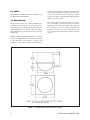
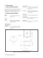
®
ED28/ED2820 and ED29/ED2920
“Harris Dome” Enclosures
Installation/Operation Manual
C460M-E (7/95)
PELCO • 3500 Pelco Way • Clovis, CA 93612-5699 • USA • www.pelco.com
(800) 289-9100 or (1-559) 292-1981 • FAX (800) 289-9150 or (1-559) 292-3827
PELCO Manual C460M-E (7/95)
33
TABLE OF CONTENTS
Section
Page
1.0
WARNINGS ........................................................................................................................................ 1
2.0
SCOPE ............................................................................................................................................... 2
3.0
DESCRIPTION ................................................................................................................................... 2
4.0
INSTALLATION ................................................................................................................................... 3
4.1 UNPACKING INSTRUCTIONS ................................................................................................... 3
4.2 CONDUCTOR REQUIREMENTS .............................................................................................. 3
4.3 WIRING INSTRUCTIONS .......................................................................................................... 4
4.4 INSTALLATION INSTRUCTIONS ............................................................................................... 7
4.4.1 Mounting the ED28/ ED2820 Series ............................................................................... 8
4.4.1.1 Wall Mounting .................................................................................................... 8
4.4.1.2 Corner Mounting ................................................................................................ 9
4.4.1.3 EDM210 Mounting Extension .......................................................................... 11
4.4.1.4 Parapet or Pole Mounting ................................................................................. 12
4.4.2 Mounting the ED29/ ED2920 Series ............................................................................. 13
4.5 LIMIT/STOP ADJUSTMENTS ................................................................................................... 13
5.0
CARE AND MAINTENANCE ............................................................................................................ 13
5.1 RECOMMENDED EQUIPMENT AND TOOLS ......................................................................... 13
5.2 SERVICE TIPS ......................................................................................................................... 13
6.0
ED28 EXPLODED ASSEMBLY DIAGRAM ...................................................................................... 14
7.0
ED28 MECHANICAL PARTS LIST ................................................................................................... 15
8.0
INSTALLATION ................................................................................................................................. 16
8.1 WIRING .................................................................................................................................... 16
8.2 CONDUCTOR AND CABLE REQUIREMENTS ....................................................................... 16
8.3 CONNECTOR ASSEMBLY ...................................................................................................... 17
8.4 LIMIT/STOP ADJUSTMENTS .................................................................................................. 21
9.0
OPERATIONAL TEST ...................................................................................................................... 21
9.1 CONTROL ................................................................................................................................ 21
9.2 AUTO/RANDOM SCAN OPERATION ...................................................................................... 22
10.0 MAINTENANCE ............................................................................................................................... 22
10.1 RECOMMENDED EQUIPMENT .............................................................................................. 22
10.2 SERVICE TIPS ......................................................................................................................... 22
11.0 EXPLODED ASSEMBLY DIAGRAM (PT2801000ASSY) ................................................................. 23
11.1 EXPLODED HARDWARE DIAGRAM (MODEL PT2801000ASSY) ......................................... 24
12.0 MECHANICAL PARTS LIST PT2801002ASSY/PT2801003ASSY .................................................. 25
12.1 MECHANICAL HARDWARE LIST (PT2801000ASSY ............................................................. 26
13.0 ENCLOSURE MODELS ................................................................................................................... 27
13.1 OPTIONS ................................................................................................................................. 27
ii
PELCO Manual C460M-E (7/95)
14.0 ENCLOSURE SPECIFICATIONS .................................................................................................... 28
15.0 PAN/TILT ASSEMBLIES ................................................................................................................... 29
15.1 ASSEMBLY DESCRIPTION ..................................................................................................... 29
16.0 ASSEMBLY SPECIFICATIONS ........................................................................................................ 29
16.1 ASSEMBLY MODELS .............................................................................................................. 29
17.0 PAN/TILT ASSEMBLY INSTALLATION ............................................................................................ 30
18.0 WARRANTY AND RETURN INFORMATION .................................................................................. 32
LIST OF ILLUSTRATIONS
Figure
1
2
3
4
5
6
7
8
9
10
11
12
13
14
15
16
17
18
19
20
21
22
Page
ED28/ED2820 Dimension Diagram ............................................................................................ 2
ED29/ED2920 Dimension Diagram ............................................................................................ 3
120VAC Heater/Blower Wiring Diagram ..................................................................................... 4
230 VAC Heater/Blower Wiring Diagram .................................................................................... 5
Receiver/Pan and Tilt Wiring Harness (Non-PP) ........................................................................ 6
Receiver/Preset Pan and Tilt With Alarm Output Wiring Diagram .............................................. 6
Coaxitron/Wiretron Power Patch Wiring Schematic ................................................................... 7
Camera/Lens Mounting .............................................................................................................. 8
Wall Mounting ............................................................................................................................. 8
Corner Mounting ........................................................................................................................ 9
Mounting Templates ................................................................................................................. 10
EDM210 Mounting Extension Illustration ................................................................................. 11
ED28/ED2820 Series Parapet or Pole Mount .......................................................................... 12
ED28 Exploded Assembly Diagram ......................................................................................... 14
Connector Assembly ................................................................................................................ 17
PT2801000ASSY/PT2801001ASSY Wiring Diagram .............................................................. 18
PT2801002ASSY Wiring Diagram ........................................................................................... 19
PT2801003ASSY Wiring Diagram ........................................................................................... 20
Limit Stops ................................................................................................................................ 21
Exploded Parts Assembly Diagram (PT2801000ASSY) .......................................................... 23
Exploded Hardware Assembly Diagram (PT2801000ASSY) ................................................... 24
ED28KIT Installation/Exploded View ........................................................................................ 31
Pelco, the Pelco Logo, Camclosure, Esprit, Genex, Legacy, and Spectra are registered trademarks of Pelco.
Endura and ExSite are trademarks of Pelco.
PELCO Manual C460M-E (7/95)
© Copyright 1995, Pelco. All rights reserved.
iii
REVISION HISTORY
Manual #
Date
Comments
C460M
3/89
Original Version.
C460M
6/90
Revision A. Manual separated into two parts: enclosures
and pan/tilt. Completely revised to include ED2820RX/PP
and ED2820SL-RX/PP models.
C460M
11/90
Revision B. Figure 2-4 revised.
C460M
6/92
Revision C. Completely revised to include the following
models: ED2820-3, ED220-PP, ED2820SL/PP,
ED2820WX, ED2820SL-WX, and ED29/ED2920 Series.
C460M-D
2/95
Revision D. Parts I and II integrated into one complete
manual. Models ED2920-3 added. Figures 3, 4 and 7
revised. New Figure 21 added as per ECO92-216 with
installation instructions for ED28KIT. New pan/tilt assembly numbers PT2801000ASSY, PT2801001ASSY,
PT2801002ASSY, and PT2801003ASSY incorporated into
manual. Incorporated new exploded assembly diagrams
and new parts/hardware materials lists.
C460M-E
7/95
Revision E. Manual revised to include the addition of
newly-created ED29-3 enclosure as per ECO # 95-195.
Items 14 and 25 in section 12.0, parts list, revised.
6/96
Corrected part number for item number 51 (Connector, 9position) also relaced Figure 21 (ED28KIT Installation/
Exploded View).
8/96
Revised Section 7.0, ED28 Mechanical Parts List, regarding part numbers for dome.
iv
PELCO Manual C460M-E (7/95)
INSTALLATION/OPERATION MANUAL
MODEL ED28, ED2820, ED29, ED2920
SERIES “HARRIS DOME” ENCLOSURES
1.0 WARNINGS
Prior to installation and use of this product, the following
WARNINGS should be observed.
1.
Installation and servicing should only be done by
Qualified Service Personnel and conform to all
Local codes.
2.
Unless the unit is specifically marked as a NEMA
Type 3, 3R, 3S, 4, 4X, 6 or 6P enclosure, it is
designed for Indoor use only and it must not be
installed where exposed to rain and moisture.
3.
The product bears the following marks:
4.
Only use replacement parts recommended by PELCO.
5.
After replacement/repair of this unit’s electrical components, conduct a resistance measurement between
line and exposed parts to verify the exposed parts
have not been connected to line circuitry.
7.
The weight of the camera/lens should not exceed
15 lbs.
This symbol indicates that dangerous voltage
constituting a risk of electric shock is present
within this unit.
This symbol indicates that there are important
operating and maintenance instructions in the
literature accompanying this unit.
CAUTION:
TO REDUCE THE RISK OF ELECTRICAL
SHOCK, DO NOT REMOVE COVER. NO
USER-SERVICEABLE PARTS INSIDE.
REFER SERVICING TO QUALIFIED
SERVICE PERSONNEL.
CAUTION:
RISK OF ELECTRIC SHOCK.
DO NOT OPEN.
Please thoroughly familiarize yourself with the information in this manual
prior to installation and operation.
PELCO Manual C460M-E (7/95)
1
2.0 SCOPE
The information contained within this manual covers
the Harris Environmental Dome.
combine concealed 360° surveillance with distortionfree viewing. The black opaque lower dome has a clear
viewing slot which effectively camouflages a CCTV
security/surveillance system without compromising the
quality of the video picture.
3.0 DESCRIPTION
This product was developed outside of PELCO’s normal product development process, and outside of normal working hours by Jimmy Harris, Sheet Metal Department Manager. In recognition of this extraordinary
effort, PELCO has proudly named this product the
Harris Dome.
The enclosure has been engineered for ease of installation, serviceability, and relocation. The lower dome
quickly and easily swings open with the aid of a gas strut
for convenient access to the camera and pan/tilt. The
pan/tilt can easily be removed for camera/lens service
by loosening two hex head fasteners and disconnecting
its cable.
PELCO’s Harris Environmental Dome is a discreet
outdoor surveillance enclosure designed to be mounted
to any solid wall, vertical surface, or parapet, and
completely encloses the pan/tilt and camera/lens to
Figure 1. ED28/ED2820 Series Dimension Drawing
2
PELCO Manual C460M-E (7/95)
4.0 INSTALLATION
4.1 UNPACKING INSTRUCTIONS
The dome and enclosure are shipped in separate cartons.
Make sure you have both before installing. Save the
shipping cartons and plastic packaging in case any part
of the unit has to be returned for credit or repair.
ED2820-3SL/PP
ED2820SL/PP Twenty (20), plus ground for pan/tilt,
lens and camera AC, plus two (2) for
heater/blower
ED2820-PP
Nineteen (19) plus ground for pan/
tilt, lens and camera AC, plus two (2)
for heater/blower
4.2 CONDUCTOR REQUIREMENTS
ED28
ED29
ED28-1
ED29-1
ED29-3
ED2820-RX
ED2820SL-RX Coax cable and 120 VAC power cord
See the camera manufacturer’s specifications sheet.
Two (2) conductor, plus ground for
heater/blower and recommended conductors for camera
ED2820-RX/PP
ED2820SL-RX/PP Same as ED2820-RX plus 10 conductors for alarms
ED2820-WX
ED2820SL-WX Twisted pair, coax, and 120 VAC
power cord
ED2820, ED2820-3
ED2920, ED2920-3
ED2820-SL
ED2920-SL
Eleven (11) plus ground for pan/tilt,
lens and camera AC, plus two (2) for
heater/blower
Figure 2. ED29/ED2920 Series Dimension Drawing
PELCO Manual C460M-E (7/95)
3
4.3 WIRING INSTRUCTIONS
Models ED28-1 and ED29-1
nating the need for wiring harnesses made in the field.
Wire the control cable per Section 9.3 using the applicable wiring diagrams in Figures 16 through 18, and
supply the necessary power.
These models are supplied with a factory installed
heater/blower and service light. Supply 120 VAC
power for the heater/blower and wire according to
Figures 3.
Models ED2820-RX, ED2820SL-RX,
ED2820-RX/PP, ED2820SL-RX/PP,
ED2920-RX and ED2920SL-RX
Models ED2820-3, ED2820-3SL/PP,
ED2920-3, ED29-3
When wiring the dome models with integral Coaxitron
receiver listed above, connect the coax to the controller
and plug the receiver into a 120 VAC power supply.
These models are supplied with factory-installed blower/
heater and service light. For installation, supply 230
VAC power for the blower/heater and wire according to
the diagram in Figure 4.
Models ED2820, ED2820-3, ED2820-SL,
ED2820-PP, ED2820SL/PP, ED2820-3SL/
PP, ED2920, and ED2920-SL
These Harris Dome models without receiver include the
PT2801000ASSY,PT2801001ASSY, PT2801002ASSY or
PT2801003ASSY pan/tilt assemblies which are prewired for all control functions — pan/tilt, motorized
zoom lens, camera power (24 VAC) and video.
All connections are made at the input connector, elimi-
In addition, the ED2820-RX/PP and ED2820SL-RX/
PP include preset position feedback capabilities. These
packages are equipped with PT2801002ASSY and
PT2801003ASSY pan/tilts and have the Coaxitron receiver installed and pre-wired to the pan/tilt. Since
these versions include 8 alarm inputs and 1 alarm
output, be sure to wire them according to the diagram in
Figure 6.
Models ED2820-WX and ED2820SL-WX
To wire Harris Dome models ED2820-WX and
ED2820SL-WX with integral Wiretron receiver, connect the twisted pair and coax to the controller and plug
the receiver into a 120 VAC power supply.
Figure 3. Heater/Blower Wiring Diagram (120 VAC)
4
PELCO Manual C460M-E (7/95)
Figure 4. Heater/Blower Wiring Diagram (230 VAC)
Wiring Pin Assignments Figure 3
Number
1
2
3
4
5
6
7
8
9
10
Function
Number
11
12
13
14
15
16
17
18
19
20
Iris
Zoom
Focus
Lens Common
Manual Iris
Not Used
Camera On
AC Input High
AC Input Neutral
Ground
Function
Not Used
Not Used
Heater #2
Heater #2
Not Used
Heater #1
Heater #1
AC High
AC Neutral
Ground
Number
21
22
23
24
25
26
27
28
29
30
Function
Fan
Not Used
Not Used
Fan
Not Used
Not Used
Not Used
Connected to #6
Not Used
Camera
Wiring Pin Assignments Figure 4
Number
1
2
3
4
5
6
7
8
9
10
Function
Iris
Zoom
Focus
Lens Common
Manual Iris
Not Used
Camera On
AC Input High
AC Input Neutral
Ground
PELCO Manual C460M-E (7/95)
Number
11
12
13
14
15
16
17
18
19
20
Function
Not Used
Not Used
Heater #2
Not Used
Connect Heaters 1 & 2
Not Used
Heater #1
AC High
AC Neutral
Ground
Number
21
22
23
24
25
26
27
28
29
30
Function
Fan
Not Used
Not Used
Fan
Not Used
Not Used
Not Used
Connected to #6
Not Used
Camera
5
Figure 5. Receiver/Pan and Tilt Wiring Harness (Non-PP)
1
2
3
4
5
6
7
8
9
10
10 CONDUCTOR CABLE, 3 FEET
OPEN WIRES
OUTSIDE DOME
CONA28S
BROWN
RED
ORANGE
YELLOW
GREEN
BLUE
VIOLET
GREY
WHITE
BLACK
ALARM INPUT #1
ALARM INPUT #2
ALARM INPUT #3
ALARM INPUT #4
ALARM INPUT #5
ALARM INPUT #6
ALARM INPUT #7
ALARM INPUT #8
ALARM OUTPUT
ALARM COMMON
10 POS MTA CONN
(CON1-640428-0)
WIRE AT 12 INCHES
ZS-SPIROBAND
POS.
1
2
3
4
5
6
7
8
9
10
11
12
13
14
17
18
19
20
23
24
25
28 POS CONNECTOR
COLOR
DESC.
BROWN
WHT/VIO
RED
WHT/BLK
YELLOW
ORANGE
BLUE
GREEN
WHITE
BLACK
WHT/BRN
WHT/RED
WHT/ORG
WHT/YEL
WHT/BLU
GRY/WHT
VIO/WHT
BLK/WHT
ORG/WHT
YEL/WHT
GRN/WHT
P/T COMMON
VIDEO CORE
LEFT
VIDEO SHIELD
DOWN
UP
RIGHT
GROUND
CAMERA AC HIGH
IRIS
FOCUS
ZOOM
LENS COMMEN
CAMERA AC LOW
PRESET COMMEN
PRESET HIGH
PAN PRESET B
TILT PRESET
LENS ZOOM PRESET
LENS FOCUS PRESET
PAN PRESET A
1
2
3
4
5
9
10
GRN/WHT
BLK/WHT
ORG/WTH
YEL/WHT
VIO/WHT
WHT/BLU
GRY/WHT
PAN PRESET A
TILT PRESET
LENS ZOOM PRESET
LENS FOCUS PRESET
PAN PRESET B
PRESET HIGH
PRESET COMMON
10 POS MTA CONN
(CON-640428-0)
TO RECEIVER PP BOARD
1 WHT/VIO
2 WHT/BLK
1
2
3
4
5
6
7
8
9
10
11
12
13
14
WHITE
WHT/YEL
BROWN
RED
BLUE
YELLOW
ORANGE
14 POS MTA PLUG
(CON1-640428-4)
TO RECEIVER MOTHER
BOARD
GREEN
WHT/RED
WHT/BRN
BLACK
WHT/ORG
2 POS RECEPTACLE
(CON1-480318-0)
Figure 6. Receiver/Preset Pan and Tilt With Alarm Output Wiring Diagram
6
PELCO Manual C460M-E (7/95)
Figure 7. Coaxitron/Wiretron Power Patch (CX9024RX/WX8024RX) Wiring Schematic
4.4 INSTALLATION INSTRUCTIONS
The Harris Dome is supplied in three (3) configurations:
as a passive dome (for use as a dummy dome or with a
fixed camera ), with a factory installed pan/tilt, or with
a factory installed pan/tilt and receiver/driver.
CAUTION: Make certain that the mounting surface is capable of supporting the full load of the
mount, pan/tilt, camera/lens, and enclosure.
When the pan/tilt is removed, mount the camera/lens
(see Figure 8) and make the electrical connections to the
pan/tilt (camera power, video, lens).
When closing the dome, be sure the drive tab on the
dome engages the slot on the drive arm of the pan/tilt.
WARNING: Do not rotate pan/tilt by hand. Rotate by controller only.
Handle the lower dome with care so as not to scratch or
get fingerprints on the viewing window.
When installing a dome with an integral pan/tilt, loosen
the two (2) fasteners and remove the pan/tilt to reduce
the total weight of the unit.
PELCO Manual C460M-E (7/95)
7
NOTE: VALUES IN PARENTHESES ARE CENTIMETERS; ALL OTHERS ARE INCHES.
Figure 8. Camera/Lens Mounting
4.4.1 Mounting the ED28/ED2820 Series
4.4.1.1 Wall Mounting
The ED28/ED2820 series may be mounted directly to a
wall or vertical surface. To attach the enclosure to a
vertical surface, perform the following (see Figure 9):
1.
Using the enclosure or the template supplied (see
Figure 12), mark the location of the four (4) mounting holes. If the control and power cables are to
pass through the mounting surface, mark the large
center hole as well.
2.
Drill four (4) mounting holes according to the
fasteners being used (minimum 5/16-inch diameter, not supplied).
3.
Mount the enclosure to the surface using the required fasteners. If needed, route the control cables
through the mounting structure.
4.
Install pan/tilt with camera/lens.
Figure 9. Wall Mounting
8
PELCO Manual C460M-E (7/95)
4.4.1.2 Corner Mounting
The ED28/ED2820 series may be mounted to the outside corner of a structure using the CM100 Corner
Mount Adapter.
To attach the enclosure to an outside corner, perform the
following steps (see Figure 10):
1.
Secure the CM100 corner mount adapter as stated
in the installation manual provided with the mount.
2.
Mount the enclosure to the CM100 using four (4)
1/4-inch diameter fasteners.
3.
Route the power cord and control cables through
the hole in the mount arm and make the necessary
connections.
4.
Install the pan/tilt with the camera/lens mounted.
Figure 10. Corner Mounting
PELCO Manual C460M-E (7/95)
9
ED28/ED2820 SERIES AND
EDM210 HOLE PATTERN
ST1 HOLE PATTERN
Figure 11. Mounting Templates
10
PELCO Manual C460M-E (7/95)
4.4.1.3 EDM210 Mounting Extension
2.
When needed, the ED28/ED2820 series dome may be
mounted 10 inches (25.4 cm) farther from the mounting
surface with the use of the EDM210 mounting extension. It should be noted that in areas with heavy snowfall
or high winds, the ST1 support strut should also be used.
Drill the mounting holes according to the fasteners
being used (minimum 5/16-inch diameter, not supplied, quantity 4).
3.
Mount the enclosure to the EDM210 with the
required fasteners. Route the cables through the
extension.
4.
Mount the enclosure/extension to the mounting
surface using the required fasteners. If needed,
route the control cables through the mounting structure.
5.
Install the pan/tilt with camera/lens.
To attach the enclosure to a vertical surface and incorporate the EDM210, perform the following steps (see
Figure 12):
1.
Using the enclosure, EDM210, or the template
supplied (see Figure 11), mark the location of the
four (4) mounting holes. If the control and power
cables are to pass through the mounting surface,
mark the large center hole as well.
Figure 12. EDM210 Mounting Extension Installation
PELCO Manual C460M-E (7/95)
11
4.4.1.4 Parapet or Pole Mounting
When mounting to a parapet, use of the PP200/PPI200
parapet mount or PP300/PP301 parapet corner mounts
is recommended. The ED28/ED2820 series dome may
be mounted to other standard PELCO mounts, including the PP100 Parapet Mount or the PA102 Pole Mount.
These mounts can be used in conjunction with the
EDM210 mount extension and the ST1 strut. (See
Figure 12.)
Follow the mounting instructions enclosed with the
appropriate mount and then proceed as stated in Section
4.4.1.2, step 3 or Section 4.4.1.3, step 3, as required.
PP200/PPI200
PP300/PP301 with PPI200
PP100
PA102
Figure 13. ED28/ED2820 Series Parapet or Pole Mounting
12
PELCO Manual C460M-E (7/95)
4.4.2 Mounting the ED29/ED2920 Series
5.2 SERVICE TIPS
The ED29/ED2920 Series domes require a suitable
length of 1-1/2-inch NPT threaded pipe (not supplied)
for mounting. The dome can be attached to any wall or
ceiling capable of supporting the full weight of the
mount, pan/tilt, camera/lens, and enclosure. We suggest
using the MRWA wall mount or MRCA ceiling mount.
Follow the instructions provided with the mount.
Some common problems encountered with pan/tilt systems include miswiring, overloading, and not using the
units for the correct applications. If a failure occurs, it is
recommended that the following procedures be used.
1.
If the pan/tilt ceases to operate, turn the control unit
off and remove the AC cord from the outlet.
4.5 LIMIT/STOP ADJUSTMENTS
2.
Check the fuse in the control unit using either a
voltmeter or ohmmeter. If open (blown), replace
with the proper recommended fuse.
3.
Replace the AC cord in the outlet and turn the
control on. If the fuse continues to open (blow),
turn the unit off.
4.
Check the control cable between the control unit
and pan/tilt for shorts, high resistance, or opens.
5.
If the control cable is found to be good, replace the
connector to the control unit, leave the connector
off the pan/tilt, and replace the fuse.
6.
Operate the control unit when it is disconnected
from the pan/tilt. If the fuse continues to “blow” the
fault is in the control. Refer to the appropriate
service manual for the control being used.
7.
Check the wiring harness in the pan/tilt for shorts.
8.
If the wiring harness is found to be good, then the
problem is internal to the unit; consult factory.
To adjust the pan/tilt limits, refer to Section 8.4, of this
manual.
5.0 CARE AND MAINTENANCE
Regularly scheduled maintenance will prolong the operational life and appearance of the equipment.
IMPORTANT: The lower dome of the Harris
Dome is an optical surface. When cleaning the
inner surface of the dome and viewing window,
treat as carefully as you would a fine camera lens.
1.
If dust or other debris accumulates on the inside of
the lower dome, remove them with clean air pressure. Compressed air cans are available from commercial photographic equipment and supply dealers.
WARNING: Do not use water, liquid or spray
cleaners of any kind on coated innersurface of dome.
2.
Clean the outer surface of the dome and the inner
surface of the viewing window with a nonabrasive
cleaning cloth and antistatic cleaner that is safe for
use on acrylic plastic. Do not use kerosene or
similar substances that can scratch the surface.
5.1 RECOMMENDED EQUIPMENT
AND TOOLS
1.
2.
3.
4.
5.
Voltmeter or Ohmmeter
Allen Wrench Set
Wrench Set
Flat Blade and Phillips Head Screw Drivers
Pliers, Long Nose
PELCO Manual C460M-E (7/95)
13
6.0 ED28 EXPLODED ASSEMBLY DIAGRAM
Figure 14. ED28 Exploded Assembly Diagram
14
PELCO Manual C460M-E (7/95)
7.0 ED28 MECHANICAL PARTS LIST
The following parts list corresponds to the exploded assembly diagram in Figure 14.
Item
Qty
1
2
3
4
5
6
7
8
9
10
11
12
2
2
2
1
1
1
1
1
1
1
6
1
1
4
8
4
1
4
2
1
4
4
2
2
1
4
13
14
15
16
17
18
19
20
21
22
23
24
25
Description
Fastener
Receptacle
Retainer
Holder, Lamp (not shown)
Back Box Assy
Plate, Front
Bracket, Cylinder
Bracket, Switch, Service Light
Dome, Clear 20"
Cylinder gas spring, 20#
NP Gasket, Poron
Lamp, C-7, 120 VAC (not shown)
Lamp, S-6, 230VAC (not shown)
Gasket, Filter Foam (not shown)
Bushing
Spacer, .250 OD x .375"
Dome Drive Tab
Roller, Delrin, Black
Spacer, 5/16 OD x .375"
Switch
Cable Tie, 2" (not shown)
Mount, Cable Tie (not shown)
Nut, Wing,1/4-20 (not shown)
Nut, Acorn (not shown)
Washer, #5610-22-60 (not shown)
Roller O-ring (not shown)
Part Number
ED210000
ED210001
ED210002
ED210020
ED28001001WA
ED28004003COMP
ED28004011COMP
ED28004031COMP
ED282006*
EH550010020
EH550010033
LAP7C7
LAP10S6/10
ED210006
SB310005
SB310007
SB34006COMP
SB34020COMP
SPA8542
SWIV3L
WIRCABLETIE2
WIRCABLETIEMT-2
ZH1/4-20NUTSW
ZH10-32NUTCA
ZH200X437X62N
ED210100**
* Part number is for the dome only. To order the complete dome assembly, specify the part number ED28DOMECLP, which includes items 9 and 16.
** O-ring is not used with domes that have a flange diameter of 21.32 inches ± .030 inches.
PELCO Manual C460M-E (7/95)
15
8.0 INSTALLATION
In order to ensure proper wiring and system operation of
all components, it is highly recommended that the pan/
tilt and the associated control equipment be tested in
your facility before field installation is attempted. Assemble the mating connector as outlined in Figure 15
and wire the control cable according to the applicable
diagrams provided in Figures 16 through 17 for all
models except ED28, ED28-1, ED29, ED29-1 and
models with integral receiver (RX or WX). Models with
integral receiver are pre-wired at the factory.
(Standard pan/tilt with presets)
PT2801002ASSY: Pan/Tilt (9 plus ground)
Lens (8)
Camera AC (2)
(SL pan/tilt with presets)
PT2801003ASSY: Pan/Tilt (10 plus ground)
Lens (8)
Camera AC (2)
Cable Distances — Hard-Wire Controls
Pan/Tilt Functions
8.1 WIRING
When using a Coaxitron or Wiretron Control System,
consider using the C1906 and C1925 factory assembled
pretested cables which are wired for inverted applications.
20 Awg
18 Awg
16 Awg
5 Conductors
110 feet (33.5 m)
180 feet (54.8 m)
290 feet (88.3 m)
6 Conductors*
210 feet (64 m)
330 feet (100 m)
530 feet (161 m)
*Using 2 conductor common
NOTE: If you are not using the C1906 or C1925
pretested cables, you must reverse the left/right and
up/down function pins shown in Figures 16 through
Figure 18.
Cable distances should not exceed the distances specified in Section 8.2, Conductor/Cable Requirements.
Cable fabrication must be in accordance with Figure 15.
The following are some recommended common installation practices.
Camera Power
Consult the camera manufacturer for transformer power
distances.
NOTE: A relay box (RB24) is available to extend
the operating distance (control to relay box) up to
13,000 feet (3,962 m) utilizing 16 Awg wire.
Cable Distances — Coaxitron
1.
Always use jacketed stranded multiconductor interconnecting cable between the control and the
pan/tilt unit, with additional conductors than needed
for future servicing and or additions.
2.
Always use color-coded conductors for ease of
wiring and to identify functions at a later date.
3.
Keep a wiring diagram with the system for later use
and reference.
8.2 CONDUCTOR AND
CABLE REQUIREMENTS
Conductors
Up to a maximum of 750 feet (228 m) on a single coax
(RG59/U) from the receiver to the transmitter.
NOTE: To extend the distance to 3,000 feet (914m)
on RG59/U coax, use the PELCO EA2000 Half
Duplex Equalizing Amplifier.
Cable Distances — Wiretron
Maximum recommended distances from the receiver to
the transmitter using twisted pair, unshielded cable are
as follows:
22 Awg
20 Awg
5 miles (8 km)
10 miles (16 km)
Conductor requirements are as listed, plus coax cable.
(Standard or SL pan/tilt)
PT2801000ASSY
PT2801001ASSY: Pan/Tilt (5 plus ground)
Lens (4)
Camera AC (2)
16
PELCO Manual C460M-E (7/95)
8.3 CONNECTOR ASSEMBLY
Installation and/or testing will require you to assemble
the connector parts provided. Fabricate the interconnecting cable according to the following steps (reference Figure 15).
1.
Slide part A of the cable clamp (item 1) over
the end of the cable (item 1, part C) with the
threaded end of the cable clamp facing the connector (item 5).
2.
If the cable has a diameter less than 1/2 inch
(1.3 cm), slide the rubber boot (item 2) over
the end of the cable and pull through the cable
clamp to so that the boot encases the cable and
forms a good seal.
3.
Strip back the cable jacket approximately 11/4 inches (3.2 cm) and separate the individual
conductors (item 3).
4.
The contact pins supplied with the mating connector are the “crimp” type which may also
be soldered if you so desired (item 4).
5.
After crimping or soldering the contact pins
to the conductors, push them into the proper
holes in the connector until they snap in place.
NOTE: Contacts cannot be removed from the
connector without the use of the appropriate AMP
extraction tool which is available from PELCO.
6.
Slide part A of the cable clamp toward the connector and screw the parts together. Attach part
B (item 1) onto part A and connect both parts
with the screws provided.
7.
Connect the cable assembly to the unit and
seat the connector by twisting the locking collar until it snaps into position.
Refer to Figures 16-18 for the appropriate wiring diagram.
5
1
threaded end of
cable clamp
A
B
C
STEP 1
5
1
FLEXIBLE RUBBER BOOT
A
B
STEP 2
C
2
5 **
3
4
1
A
STRIP 1/8"
B
C
STEPS 3-7
CRIMP
INSULATION
CRIMP
WIRE
OUTSIDE
JACKET
OF CABLE
STRIP 1"
**
ITEM 5 DETAIL
4
1
9
10
2
1
3
5
15
4
8
16
22
28
23
33
29
37
34
15
20
25
21
28
3
3
10
1
7
14
26
FRONT VIEW
28-PIN CONNECTOR
FRONT VIEW
37-PIN CONNECTOR
11
16
15
FRONT VIEW
16-PIN CONNECTOR
3
1
4
7
4
6
THE MOST COMMONLY USED
CONNECTOR PIN-OUT CONFIGURATIONS ARE SHOWN HERE.
REFERENCE THE CONNECTOR
DRAWING APPLICABLE TO
YOUR SITUATION.
1
6
9
14
11
8
14
9
7
12
FRONT VIEW
14-PIN CONNECTOR
FRONT VIEW
9-PIN CONNECTOR
Figure 15. Connector Assembly
PELCO Manual C460M-E (7/95)
17
QTY
2
1
1
1
14
4
1
1
1
1
SYMBOL
C1,C2
M1
M2
J2
—
S1-S4
—
—
—
—
Note:
DESCRIPTION
CAPACITOR,15 MFD,100V
PAN MOTOR
TILT MOTOR
CONNECTOR
CONNECTOR PINS
SWITCH
INPUT CONNECTOR
MATING CONNECTOR ASSY
ACTUATOR
LENS MATING CONNECTOR
MANUFACTURER
PART NUMBER
SPRAGUE
PELCO
PELCO
HIRSCHMANN
AMP
MICROSWITCH
AMP
AMP
MICROSWITCH
HIRSCHMANN
CAPU0015.0/100N
2508001
PS78001
CONMAB6100
CON66102-7
SWI1SM1
CON206044-1
CONA14S
SWIJS138B
CONMAS6100
For non-receiver models only, you must reverse the left/right and up/down
function pins shown above if you are not using the C1906 or C1925 pretested
cables.
Figure 16. PT2801000ASSY/PT2801001ASSY Wiring Diagram
(Standard or SL Models)
18
PELCO Manual C460M-E (7/95)
Note:
For non-receiver models only, you must reverse the left/right and up/down
function pins shown above if you are not using the C1906/PP or C1925/PP
pretested cables.
Figure 17. PT2801002ASSY Wiring Diagram
(Standard with Presets)
PELCO Manual C460M-E (7/95)
19
Note:
For non-receiver models only, you must reverse the left/right and up/down
function pins shown above if you are not using the C1906/PP or C1925/PP
pretested cables.
Figure 18. PT2801003ASSY Wiring Diagram
(SL with Presets)
20
PELCO Manual C460M-E (7/95)
8.4 LIMIT/STOP ADJUSTMENTS
WARNING: Do not operate pan/tilt without limit
stops.
Do not remove or reposition the fixed actuator on
the non-SL. DAMAGE WILL OCCUR.
NOTE: SL models are not equipped with pan limit
stops. (Disregard steps 1-5 below).
To set limit stops, perform the following steps (refer to
Figure 19).
1.
Loosen the pan limit stops.
2.
Turn the control unit “on.” Pan the unit to the right
until the desired right pan limit is reached.
3.
Move the right pan limit stop until it touches the
pan limit switch actuator. Move the stop a slight
distance further against the actuator until it “clicks”,
indicating opening of the limit switch. Lock the
stop in place.
4.
Pan the unit to the desired “left” position. Adjust
the left pan limit stop as described in step 3.
5.
Pan left and right to both limit stops and check for
exact positioning. Tighten both stops securely.
Figure 19. Limit Stops
the installation cable at the job site. Splice the ends,
color-to-color, onto the cable in the field, using the
terminal blocks at each end.
9.0 OPERATIONAL TEST
6.
Remove the end cup from the left side of the tilt
table. Loosen the tilt limit stop screws and tilt the
table, using the joystick, to the desired “up” position.
7.
Move the “up” limit stop until it touches the tilt
limit switch actuator and “clicks”. Lock the stop in
place.
8.
Tilt the table to the desired “down” position and set
the stop in the same manner.
9.
Tilt the table up and down and check for exact
positioning. Tighten both stops securely. Replace
the side cover.
After the unit has been tested and stops aligned, turn off
the control and disconnect the AC cord from the outlet.
Remove the multiconductor cable from both the pan/tilt
and control unit. This cable can then be used for installation by cutting the test cable and splicing the ends onto
PELCO Manual C460M-E (7/95)
9.1 CONTROL
Connect the cable assembly between the pan/tilt and the
control unit. Plug the control unit into the AC outlet and
switch the unit on.
Move the joystick to the UP position. Observing the
“Front” label on the pan/tilt, the front of the tilt table
should move up. Move the joystick to the DOWN
position, and the front of the tilt table should move
down. Releasing the joystick should allow it to return to
center and the tilt table should immediately stop moving.
Move the joystick to the LEFT position and the complete top assembly should rotate counterclockwise.
With the joystick moved to the RIGHT position, the
unit will rotate clockwise.
Both the pan and tilt motors are protected from mechanical over-travel by electrical limits which stop the
motors.
21
9.2 AUTO/RANDOM SCAN OPERATION
10.2 SERVICE TIPS
The pan/tilt will function in the Auto/Random mode
with the addition of the appropriate PELCO control
system. The pan/tilt has no additional limit switches or
relays for auto scan operation and is, therefore, only
compatible with current sensing auto/random type circuits employed in our control systems.
Some common problems encountered with pan/tilt systems include miswiring, overloading, and not using the
units for the correct application. Should a failure occur,
it is recommended that the following procedures be
used.
1.
If the pan/tilt ceases to operate, turn the control unit
off and remove the AC cord from the outlet.
2.
Check the fuse in the control unit using either a
voltmeter or ohmmeter. If open (blown), replace
with the proper recommended fuse.
3.
Replace the AC cord in the outlet and turn the
control on. If the fuse continues to open (blow),
turn the unit off.
4.
Check the control cable between the control unit
and pan/tilt for shorts, high resistance, or opens.
5.
If the control cable is found to be good, replace the
connector to the control unit, leave the connector
off the pan/tilt, and replace the fuse.
6.
Operate the control unit when it is disconnected
from the pan/tilt. If the fuse continues to “blow” the
fault is in the control. Refer to the appropriate
service manual for the control being used.
7.
Check the wiring harness in the pan/tilt for shorts.
8.
If the wiring harness is found to be good, then the
problem is internal to the unit; consult factory.
10.0 MAINTENANCE
10.1 RECOMMENDED EQUIPMENT
AND TOOLS
1.
2.
3.
4.
5.
Voltmeter or Ohmmeter
Allen Wrench Set
Wrench Set
Flat Blade and Phillips Head Screwdrivers
Pliers, Long Nose
Refer to Figures 16 through 18, if necessary.
22
PELCO Manual C460M-E (7/95)
11.0 EXPLODED ASSEMBLY DIAGRAM (Model PT2801000ASSY)
Figure 20. Exploded Assembly Parts Diagram (Model PT2801000ASSY)
PELCO Manual C460M-E (7/95)
23
11.1 EXPLODED HARDWARE DIAGRAM (Model PT2801000ASSY)
Figure 21. Exploded Assembly Hardware Diagram (Model PT2801000ASSY)
24
PELCO Manual C460M-E (7/95)
12.0 MECHANICAL PARTS LIST (PT2801000ASSY)
The following parts list corresponds to the exploded assembly diagram in Figure 20.
Item
Qty
1
4
2
1
1
1
2
1
2
1
1
1
1
2
2
1
1
1
1
1
1
1
1
1
1
1
1
1
1
1
1
1
1
1
3
1
2
1
1
1
4
2
4
2
1
1
1
1
1
1
1
1
1
1
2
3
4
5
6
7
8
9
10
11
12
13
14
15
16
17
18
19
20
21
22
23
24
25
26
27
28
29
30
31
32
33
34
35
36
37
38
39
40
41
42
43
44
PELCO Manual C460M-E (7/95)
Description
Ring, Snap #Q2-18
Ring, Snap #Q2-18 (SL)
Pin, Pan Limit (Non-SL)
Pin, Pan Limit (P/PP Only)
Pin, Tilt Limit
Tilt Limit Stop
Bracket, Tilt Limit
Cover Plate, Tilt
Pin, #1 X 1-1/4 Taper
Nut, Spindle
Clamp, Cable (SL Only)
Spacer, Tilt Collar
Bearing, Pan Spindle
Bearing, Tilt FB68-31/4
Tilt Shaft Assembly
Chain Assembly, Pan
Chain Assembly, Tilt
Sprocket, 25B20-3/8 W/SS
Tilt Table
Cover
Bracket, Pan & Tilt Motor, Black
Sprocket, Motor
Bracket, Pan Limit (Non-SL Only)
Plate Bottom
Sideplate, Pan
Spindle
Sprocket, 25B13-3/8
Motor, Pan 2-RPM, 24 VAC
Plate, Side Tilt (Non PP)
Plate, Side Tilt (PP)
Bracket, Pan Motor
Spacer, Pan Motor
Sprocket, Pan Spindle
Limit Stop, Pan
Connector, 6-Position (SL and P Only)
Gromet, Neoprene
Gromet, Neoprene (SL)
Motor, 24 VAC, 1-RPM
Spacer, 5/16 Dia X 1.25 #10 Clear
Switch, Micro
Switch, Micro (SL)
Switch Actuator W/Insulator
Switch Actuator W/Insulator (SL)
Terminal Strip, 7-pin (Non-PP)
Terminal Strip, 9-pin (PP Only)
UL, Gland SL-9
UL, Nut
Bracket, PM200C
Bracket, Slip Ring (SL/PP)
Bracket, Slip Ring (P/PP)
Cover, Slip Ring
Ring, Slip for Preset (SL/PP)
Ring, Slip 24-inch Leads (SL)
Part Number
15510000
15510000
1554049COMP
2804003COMP
1554049TCOMP
1554050COMP
1554052COMP
1554053COMP
17510000
25010002
2504007COMP
2504015COMP
2506000
2506001
2701002COMP
2801010COMP
2701004COMP
27012008
2704003COMP
2704004COMP
2704006COMP
2704010COMP
2704051COMP
2704100COMP
270412COMP
274105COMP
28012011
2804001COMP
2804002COMP
2804102COMP
2804012COMP
2804013COMP
2804019COMP
5804006COMP
CONMAB6100
GRO2172N
GRO2172N
PS78001
SPA8548
SWI1SM1
SWI1SM1
SWIJS138B
SWIJS138B
TRS2007
TRS2009
EH400010003
EH400010004
PM200C4000COMP
SL28004101COMP
SL28004001COMP
SL28004100COMP
250010000
28010000
25
Item
Qty
45
1
1
1
1
1
1
1
1
1
1
1
1
46
47
48
49
50
51
52
53
Description
Part Number
Gear, SP Delrin (SL/PP)
Gear, 1.875 Plastic (P/PP)
Gear, SP Delrin
Bracket, Pot Pan (P/PP)
Bracket, Pot Pan (SL/PP)
Bracket, Pot Pan
Gear, Preset Pan Spindle
Gear, Preset Tilt Shaft
Connector, 9-position (PP Only)
Pot, Dual Arm Pre Res (SL/PP)
Pot, Precision, 10K (P/PP)
Gear, 1.875 Plastic (P/PP)
280010016
PT250010002
28010017
2804014COMP
2804117COMP
2804015COMP
2804016COMP
2804020COMP
CON206705-1
POTDARM010.0K
POT010.0K
POT10.0K
12.1 MECHANICAL HARDWARE LIST (PT2801000ASSY)
The following parts list corresponds to the exploded assembly diagram in Figure 21.
Item
Qty
A
B
C
D
E
F
G
H
I
J
4
3
3
1
2
6
1
8
8
8
4
1
1
6
4
1
6
2
4
4
2
3
4
2
4
4
7
3
3
6
3
1
7
4
1
1
1
K
L
M
N
O
P
Q
R
S
T
U
V
W
X
Y
Z
AA
BB
CC
DD
EE
FF
GG
26
Description
Part Number
Bolt, 1/4-20 X 5/8 Phil Flat SS
Screw, 1/4-20 X 5/8 Hex C/S SS (SL Only)
Washer, Split Lock Medium (SL Only)
Screw, 10-32 X 3/8 Pan Phil SS (SL Only)
Screw, 10-32 X 7/16 Socket Head C/S SS
Screw, 10-32 X 1/2 Socket Head C/S SS
#10 Internal Tooth Lockwasher (SL Only)
Washer, Split Lock #10 SS Medium
Washer, Flat #10 SS
Screw, 2-56 X 4/16 Pan Phil SS
Screw, 2-56 X 4/16 Pan Phil SS (SL)
Set Screw, 10/32 X 1/8 Socket Knurl Blk
Set Screw, 10/32 X 3/16 Socket Knurl Blk
Screw, 4-40 X 1/4 Pan Phil SS
Screw, 4-40 X 3/8 Pan Phil (PP Only)
Screw, 4-40 X 5/8 Pan Phil SS
#4 Internal Tooth Lockwasher SS
Set Screw, 6-32 X 3/16 Socket Knurl Blk
Screw, 6-32 X 1/4 Pan Phil SS
Screw, 6-32 X 3/8 Socket C/S SS
Screw, 6-32 X 3/8 Pan Phil SS
Screw, 6-32 X 1/2 Socket C/S
Set Screw, 6-32 X 3/4 SS
Screw, 6-32 X 2 Pan Phil SS
Nut, 6-32 Acorn SS
Nut, Hex 6-32 SS
#6 Internal Tooth Lockwasher (PP Only)
#6 Internal Tooth Lockwasher (P Only)
Washer, Split Lock #6 SS Med
Screw, 8-32 X 3/8 Pan Phil SS (SL Only)
Screw, 8-32 X 3/8 Pan Phil SS (P Only)
Screw, 8-32 X 5/8 Pan Phil SS
Washer, Internal Star (SL Only)
Washer, Internal Star (P Only)
Pin, Roll 3/32 X 1/2
Pin, Roll 3/32 X 1/2
Pin, Dowel 1/8 X 5/8 Hardened Steel
ZH1/420X.625SFS
ZH1/420X.625CH
ZH1/4LWSSL
ZH10-32X.375SPP
ZH10-32X.437CS
ZH10-32X.500CS
ZH10LWSIS
ZH10LWSSL
ZH204X436X60C
ZH2-56X.437SPP
ZH2-56X.437SPP
ZH10-32X.187S
ZH3/8-24X.375SS
ZH4-40X.250SPP
ZH4-40X.375SPP
ZH4-40X.625SPP
ZH4LWSIS
ZH6-32X.187S
ZH6-32X.250SPP
ZH6-32X.375CS
ZH6-32X.375SPP
ZH6-32X. 500CS
ZH6-32X.750SS
ZH6-32X2.00SPS
ZH6-32NUTCA
ZH6-32NUTSH
ZH6LWSIS
ZH6LWSIS
ZH6LWSSL
ZH8-32X.375SPP
ZH8-32X.375SPP
ZH8-32X.375SPP
ZH8LWSIS
ZH8LWSIS
ZHPIN3/32X1/2R
ZHPIN3/32X3/4R
1510001
PELCO Manual C460M-E (7/95)
13.0 ENCLOSURE MODELS
ED28
Harris environmental discreet surveillance enclosure with black opaque
lower dome with clear viewing window for outdoor applications. Fixed
camera mount supplied. (UL, CE)
ED2820SL-RX/PP Same as ED2820SL-RX except sup-
plied with PT2801003ASSY pan/tilt
assembly with 360° pan rotation and
preset positioning capabilities. (UL)
ED2820-WX
Same as ED2820-RX except has
Wiretron receiver/driver.
ED28-1
Same as ED28 except supplied with
factory installed heater/blower and
service light. (UL)
ED2820SL-WX Same as ED2820-WX except supplied with PT2801001ASSY pan/tilt
assembly with 360° pan rotation. (UL)
ED2820
Harris environmental discreet surveillance system factory assembled
with PT2801000ASSY pan/tilt assembly. Heater/blower and service
light are standard features. (UL)
ED29
Same as ED28 except pendant mount
version.
ED29-1
Same as ED28-1 except pendant
mount version.
ED2820-3
Same as ED2820 except 230 VAC
blower, heater and service light.
ED29-3
Same as ED29-1 except 230 VAC
blower/heater with service light. (CE)
ED2820-PP
Same as ED2820 except supplied with
PT2801002ASSY pan/tilt assembly
with preset positioning capabilities.
(UL)
ED2920
Same as ED2820 except pendant
mount version. (UL)
ED2920-3
Same as ED2920 except 230 VAC
blower/heater and service light.
ED2920-RX
Same as ED28280-RX except pendant mount version.
ED2920-SL
Same as ED2820-SL except pendant
mount version. (UL)
ED2820-RX
Harris environmental discreet surveillance system factory assembled
with PT2801000ASSY pan/tilt and
Coaxitron receiver/driver. Heater/
blower and service light are standard
features. (UL)
ED2820-RX/PP Same as ED2820-RX except supplied with PT2801002ASSY preset
position feedback pan/tilt assembly.
(UL)
ED2820-SL
Same as ED2820 except supplied with
PT2801001ASSY pan/tilt assembly
with 360° pan rotation. (UL)
ED2820SL/PP
Same as ED2820-SL except supplied
with PT2801003ASSY pan/tilt assembly with 360° pan rotation and
preset positioning capabilities. (UL)
ED2920SL-RX Same as ED2820SL-RX except pendant mount version. (UL)
NOTE: ED29/ED2920 Series domes require a
suitable length of 1-1/2" NPT threaded pipe for
mounting.
13.1 OPTIONS
ED2820-3SL/PP Same as ED2820SL/PP except 230
VAC blower/heater and service light.
ED2820SL-RX Same as ED2820-RX except supplied with PT2801001ASSY pan/tilt
assembly with 360° pan rotation. (UL)
PELCO Manual C460M-E (7/95)
ED28KIT
Installation kit; required to retrofit
ED28, ED28-1, ED29, or ED29-1
dome with pan/tilt assembly. (See
Section 17.)
TI2800
Low temperature kit; thermal insulation with two 80 watt heaters to allow
operation in temperatures below
-10°F (-23°C).
27
14.0 ENCLOSURE SPECIFICATIONS
Fuse Protection: 3 AG type
MECHANICAL
Enclosure
Dome Drive:
Dome rides on rollers and is driven
by drive arm of pan/tilt
Control Method: 15-pulse train (pulse width modulated) superimposed on the video signal during the vertical interval by the
control transmitter. Pulse train occupies one TV line period.
Max. Camera/Lens
Length:
14.0 inches (35.5 cm)
ELECTRICAL
Enclosure (All models except ED28/ED29)
Input Voltage:
Power
Requirements:
Blower:
120 VAC 50/60Hz (or 230 VAC, 50/
60 Hz for ED2820-3 and ED28203SL/PP, ED29-3)
80 cfm at 13 watts (or 90 cfm at 15
watts for ED2820-3 and ED28203SL/PP only)
Two (2) at 80 watts each
Service Light:
One (1) at 7 watts (or One (1) at 10
watts for ED2820-3 and ED28203SL/PP only)
3-wire grounded, 18 Awg (supplied
on “RX” versions only)
Receiver
(Models ED2820-RX, ED2820SL-RX, ED2820-RX/
PP, ED2820SL-RX/PP, ED2820-WX, ED2820SL-WX,
ED2920-RX, and ED2920SL-RX only)
Power Cord:
3 wire grounded, 18 Awg (supplied)
Cables:
Coaxitron
Video: RG59 with BNC jack
Control: RG59 with BNC jack
Wiretron
Video: Coax
Control: Twisted pair, unshielded
Input Voltage:
Power
Requirements:
28
System
Bandwidth:
Operating
Distance:
180 vA (or 185 vA for ED2820-3 and
ED2820-3SL/PP only)
Heaters:
Power Cable
Requirements:
Input Video Line:1 v p-p nominal; 2v p-p maximum at
less than 75% APL; 1.5v p-p maximum at 90% APL.
120 VAC, 50/60Hz
Less than 2 dB down at 10 MHz
750 feet (228m) on RG59U
1,500 feet (457m) on RG6
1,800 feet (548m) on RG11
(75 ohm coax required)
GENERAL
Enclosure
Dimensions:
Construction:
Upper Box
Lower Dome
See Figures 1 and 2
Formed aluminum
Acrylic hemisphere with distortion
free viewing window
Finish:
Polyvinyl powder coat
Weight:
ED28
25 lbs (11.34 kg)
ED28-1
27 lbs (12.25 kg)
ED2820, ED2820-3
ED2820-SL,
ED2820-3SL/PP,
ED2820SL/PP 35 lbs (15.75 kg)
ED2820-RX,
ED2820SL-RX,
ED2820SL-RX/PP,
ED2820-WX,
ED2820SL-WX 42 lbs (18.90 kg)
ED29,
ED2920 Series
47 lbs (21.291 kg)
Temp. Range:
-10°F to 140°F (-23°C to +60°C)
79 vA (receiver only)
PELCO Manual C460M-E (7/95)
15.0 PAN/TILT ASSEMBLIES
15.1 ASSEMBLY DESCRIPTION
ELECTRICAL
The pan/tilt assembly is a “mini” light duty pan/tilt for
loads up to 15 lbs (6.8 kg) and is factory pre-wired for
all control functions (pan and tilt, motorized zoom lens,
24 VAC camera power, and video). All connections are
made at the input connector, eliminating the need for
wiring harnesses. This greatly reduces installation time,
while increasing reliability and serviceability.
Input Voltage:
Power
Requirements:
Running
Pan — .31 amp (7.5 vA)
Tilt — .38 amp (9.2 vA)
Starting
Pan — .47 amp (11.2 vA)
Tilt — .56 amp (13.5 vA)
15.2 ASSEMBLY MODELS
PT2801000ASSY Mini light-duty pan/tilt, 24 VAC, with
0-355° pan and tilt
24 VAC required for pan/tilt
Maximum
Current:
PT2801001ASSY Mini light duty pan/tilt with 360° pan
rotation, 24 VAC
2 amps per conductor (SL models
only)
Connectors:
Pan/Tilt Amp CPC type (mate supplied). Installed onto a pigtail exiting
from base of pan/tilt (all functions —
camera power, lens, video, pan/tilt).
PT2801002ASSY Same as PT2801000ASSY except
with position feedback modification
which allows pan/tilt to be automatically positioned to various preset
positions
PT2801003ASSY Same as PT2801001ASSY except
with position feedback modification
which allows pan/tilt to be automatically positioned to various preset positions
Lens:
Hirschmann MAB6100
Video:
BNC
Camera Power:
Spade lugs
Motors:
Two-phase induction type. Continuous duty, instantaneous reversing
16.0 ASSEMBLY SPECIFICATIONS
MECHANICAL
Pan:
Movement in horizontal plane:
PT2801000ASSY,
PT2801002ASSY 0-355° @ 10°/sec ±1°
PT2801001ASSY,
PT2801003ASSY 360°
Tilt:
±90° movement in vertical plane at
3°/sec ±.5°
(no load condition)
Maximum Load: 15 lbs (6.8 kg)
PELCO Manual C460M-E (7/95)
Limit Switches: Pan — 5 amp
Tilt — 5 amp
External adjustment
Cable Distances: (See Section 8.2)
GENERAL
Construction:
Aluminum
(Product specifications subject to change
without notice.)
29
17.0 PAN/TILT ASSEMBLY
INSTALLATION
2.
This section covers the installation of the ED28KIT in
retrofitting a non-pan/tilt-equipped ED28 and ED28-1
or ED29/ED29-1/ED29-3 Harris Dome with a pan/tilt
assembly unit. Please read through and understand the
installation instructions before proceeding with the installation.
Again, make sure the dome drive bracket is oriented correctly so the front of the pan and tilt
assembly will face the viewing slot in the dome
enclosure.
3.
Mount the pan and tilt assembly, with the installed
dome drive bracket and the assembly mounting
bracket, to the inside of the enclosure. Make sure
the direction of the pan and tilt assembly is oriented
properly.
4.
Make sure all hardware is tightened securely.
5.
Make the proper electrical connections.
NOTE: When installing a pan/tilt unit to a dome
enclosure, it is recommended that one of the following pan/tilt assembly units be used in the installation:
PT2801000ASSY – for non-PP operation
PT2801001ASSY – for SL operation
PT2801002ASSY – for PP operation
PT2801003ASSY – for SL/PP operation
NOTE: Refer to Installation/Operation manual
C460M for complete wiring and operation information.
(The pan/tilt assembly must be ordered separately.)
Before proceeding with the installation, make sure you
have the following:
Install the dome drive bracket to the top of the pan
and tilt assembly using the (2) mounting screws
and washers as shown in Figure 21.
6.
Close the dome, aligning the dome drive bracket
with the drive tab on the edge of the dome.
(1) P/T assembly mounting bracket,
PM200C4000COMP
(1) Dome Drive Bracket,
SB34105COMP
See Figure 21 for the assorted mounting hardware part
numbers and quantities.
NOTE: If you are working with a SL (360°) pan/
tilt assembly unit (PT2801001ASSY, or
PT2801003ASSY), skip to step 2 in the following
instructions.
1.
Install the pan and tilt assembly mounting bracket
to the top of the pan and tilt unit using the (3)
mounting screws and washers as shown in Figure
21.
Make sure the bracket is oriented such that when
the pan and tilt assembly is mounted to it, the front
of the pan and tilt unit will face toward the viewing
slot in the enclosure dome.
30
PELCO Manual C460M-E (7/95)
Figure 21. ED28KIT Installation/Exploded View
Exploded Assembly Parts List
Item
Qty
Description
Part Number
1
2
1
1
Bracket
Dome drive bracket
PM200C4000COMP
SB34105COMP
A
B
C
D
E
F
3
2
3
5
2
2
Bolt, 1/4-20 x 5/8" hex C/S
Nut lock, 1/4-20, nylon insert SS
Washer, split lock, 1/4" SS
Washer, flat, nylon
Screw, 10-32 x 3/8", pan phil SS
Washer, split lock #10 SS
ZH1/4-20X.625CH
ZH1/420NUTCHN
ZH1/4LWSSL
ZH260X562X65C
ZH10-32X.375SPP
ZH10LWSSL
PELCO Manual C460M-E (7/95)
31
18.0 WARRANTY AND RETURN
INFORMATION
WARRANTY
RETURNS
Pelco will repair or replace, without charge, any merchandise proved
defective in material or workmanship for a period of one year after the date
of shipment.
Exceptions to this warranty are as noted below:
In order to expedite parts returned to the factory for repair or credit, please
call the factory at (800) 289-9100 or (559) 292-1981 to obtain an
authorization number (CA number if returned for credit, and RA number
if returned for repair).
• Five years on FT/FR8000 Series fiber optic products.
All merchandise returned for credit may be subject to a 20% restocking
and refurbishing charge.
• Three years on Genex® Series products (multiplexers, server, and
keyboard).
• Three years on Camclosure® and fixed camera models, except the
CC3701H-2, CC3701H-2X, CC3751H-2, CC3651H-2X, MC3651H-2,
and MC3651H-2X camera models, which have a five-year warranty.
• Two years on standard motorized or fixed focal length lenses.
• Two years on Legacy®, CM6700/CM6800/CM9700 Series matrix, and
DF5/DF8 Series fixed dome products.
• Two years on Spectra®, Esprit®, ExSite™, and PS20 scanners, including when used in continuous motion applications.
• Two years on Esprit® and WW5700 Series window wiper (excluding
wiper blades).
• Eighteen months on DX Series digital video recorders, NVR300
Series network video recorders, and Endura ™ Series distributed
network-based video products.
• One year (except video heads) on video cassette recorders (VCRs).
Video heads will be covered for a period of six months.
• Six months on all pan and tilts, scanners or preset lenses used in
continuous motion applications (that is, preset scan, tour and auto scan
modes).
Pelco will warrant all replacement parts and repairs for 90 days from the
date of Pelco shipment. All goods requiring warranty repair shall be sent
freight prepaid to Pelco, Clovis, California. Repairs made necessary by
reason of misuse, alteration, normal wear, or accident are not covered
under this warranty.
Pelco assumes no risk and shall be subject to no liability for damages or
loss resulting from the specific use or application made of the Products.
Pelco’s liability for any claim, whether based on breach of contract,
negligence, infringement of any rights of any party or product liability,
relating to the Products shall not exceed the price paid by the Dealer to
Pelco for such Products. In no event will Pelco be liable for any special,
incidental or consequential damages (including loss of use, loss of profit
and claims of third parties) however caused, whether by the negligence
of Pelco or otherwise.
The above warranty provides the Dealer with specific legal rights. The
Dealer may also have additional rights, which are subject to variation from
state to state.
If a warranty repair is required, the Dealer must contact Pelco at (800)
289-9100 or (559) 292-1981 to obtain a Repair Authorization number
(RA), and provide the following information:
Goods returned for repair or credit should be clearly identified with the
assigned CA or RA number and freight should be prepaid. Ship to the
appropriate address below.
If you are located within the continental U.S., Alaska, Hawaii or Puerto
Rico, send goods to:
Service Department
Pelco
3500 Pelco Way
Clovis, CA 93612-5699
If you are located outside the continental U.S., Alaska, Hawaii or Puerto
Rico and are instructed to return goods to the USA, you may do one of the
following:
If the goods are to be sent by a COURIER SERVICE, send the goods to:
Pelco
3500 Pelco Way
Clovis, CA 93612-5699 USA
If the goods are to be sent by a FREIGHT FORWARDER, send the goods
to:
Pelco c/o Expeditors
473 Eccles Avenue
South San Francisco, CA 94080 USA
Phone: 650-737-1700
Fax: 650-737-0933
1. Model and serial number
2. Date of shipment, P.O. number, Sales Order number, or Pelco invoice
number
3. Details of the defect or problem If there is a dispute regarding the
warranty of a product which does not fall under the warranty conditions
stated above, please include a written explanation with the product
when returned.
Method of return shipment shall be the same or equal to the method by
which the item was received by Pelco.
This equipment contains electrical or electronic components that must be recycled properly to comply with Directive 2002/96/EC of the European Union
regarding the disposal of waste electrical and electronic equipment (WEEE). Contact your local dealer for procedures for recycling this equipment.
32
PELCO Manual C460M-E (7/95)