1
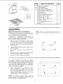
SAVE TH_S MANUAL
FOR FUTURE
REFERENCE
Serial
Number
Model and serial
number may be found
at the right-hand side
of the frame.
You should record both
model and serial
number in a safe place
for future use.
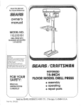
CAUTION:
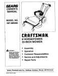
IO.INCH
SA
Read GENERAL and
ADDiTiONAL
SAFETY
iNSTRUCTiONS
ECT
IVE
* assembly
. operating
carefully
o repair parts
Sold
Part No. 69182
by SEARS,
ROEBUCK
AND
CO., Chicago,
IL. 60684
U.S.A.
FULL
H within
material
one year from
or workmanship,
WARRANTY
SERVICE
CENTERtDEPARTMENT
THiS
ONE YEAR
WARRANTY
This warranty
state _o stale,
IS AVAILABLE
THROUGHOUT
you
ONLY
specific
t_
KNOW
YOUR
POWER
THIS PRODUCT
legat rights,
safety
and you
GROUND
Th_'_
KEEP
and
4.
5,
6.
3
13.
Drm_
7.
t_ower
due
I)@ kel.)t
WORKSHOP
FORCE
USE RIGHT
WEAR
and
16.
Wear
SAFETY
safety
o_ saw
foot,rig
TOOTS
vary from
tooJs
and ear protectors
extended
periods
of
a safe
dmtance
horn
S',gqtCheS.
or
bv
r@
safer
at the
fate
to do a job
(must
with
best and safest
for !ubricating
iniury
cutting
Do
store
accessories
STARTING
is
in
"OFF"
posdion
before
ACCESSORIES
owner's
Follow
STAND
manual
the
accessories.
may cause
for recommended
instructions
that
The
use
hazards.
of
im-
ON TOOL
could
occur
if the toot is f_pped
too_ is accider,
taily contacted.
materials
above
that it is necessary
them.
DAMAGED
21. DIRECTION
OF
or
to stand
near
on
the
the
toot
tool
to
PARTS
or other
checkand
aligr>
parts_
FEED
Feed
work
into
a
direction
of rotation
22.
Prolection)
comply
times.
breakage
of parts, r'nount_ng,
and any other
conditions
that may affect
its operation.
A guard or
other
part that is damaged
should
be properly
repaired
or replaced.
APPAREL
(Head
at all
ed to ensure
that _t wdi operate
properly
peHorrn
its intended
function.
Check
for
rnent of rr'_oving parts, binding
of moving
_t was
both
CARE
when
changing
bits, cutters,
etc.
ACCIDENTAL
not
baiance
Before
further
use of the tool.
a guard
part that is darnaged
shouid
be carefuily
for
practD
frees
TOOLS
Serious
or if the
20. CHECK
arid
and
WITH
RECOMMENDED
such
reach
when
hand,
ng accessories
accompany
the
proper
accessories
TOOL
GOGGLES
chang_
(.}onsull
the
accessories
or we_ locaIions
work
your
sharp and clean
for
Foitow
instructions
DISCONNECT
18. USE
CHILD-PROOF
goggles
which
or a v_se to ho!d
_ake
sure switch
plugging
in.
Do not wear loose clothing,
gloves,
neckhes
or
jewelry
_rings,
wristwatches)
to get caught
in
moving
parts
NONSLIP
footwear
is
recom.
mended.
Wear
protective
hair covering
to contain
!ong
hair.
Rot!
long
sleeves
above
the
eibow.
12. USE
dUi'ir_g
bef<_re
servicing;
such as blades,
TOOL
PROPER
STATES.
OVERREACH
19. NEVER
Don't
force toot of attachment
not designed
for.
tl,
_O wax
AWAY
DON'T
DON'T
17. AVOID
KEEP
MAKE
SERVICE
WORK
cla,,r_ps
K.eep proper
a<c_dents
to ram
Keep
work
area welt
adequate
surrounding
work
It w_!I do the job better
wh<:h
it was des_gnecL
10.
mw_e
m damp
-- w_{h p(.adiocks,
r]'laster
mowng
sfader
keys
9.
t4.
ENVIRONMENT
Should
_s dusty,
(;a_ It's .safer tf_ar_ us_r_f!
hands
tO operate
tooi_
tool
_orn
or expose
them
_Hjhted
Provide
SDaCe
At_ vtsdors
work area
8.
siippery
tools
CHILDREN
rights
in
}L 60684
TT1Uf{S)
15. MAINTAIN
_rx._ ren]ove(_
no1 be
other
operation
Or
Keeb tools
Derforn_ance.
DANGEROUS
u,_e
have
SECURE
Use
IN PLACE
KEEP WORK AREA CLEAN
Chdtered
areas
and ben,;hen
AVOID
may also
WHUGS
',,%qth ;_r'_ cg_DrOW:_d
wrencl_es
must
SEARS
iS USED IN THE UNITED
cul!m{:_
REMOVE
ADJUSTING
KEYS AND WRENCHES
[:Orm _ b, abH Of checkmq
_ F_x? lrw]! _'v'<
_ncI
F_oot
dUSl
NEAREST
to a defect
Z87.1)
at a{! times.
Everyday
eyegiasses
only
have
ir_pact
resistant
lenses,
they
are NOT
saf_,,y 9_asses.
Also.
use face
of dust mask
_f
ah(jnmen_
adjus_ln_
due
opera_ ran.
___ equip'0@d
GUARDS
fails
for power
TOOL
COndUCtO_ COrd and a 3-pronq
gtounom_g
Wpe
pit_q to h! the proper
_roundmg
type rece[)tacte
The qT@et_ G_.)ndi.Jctor +n tr_e cord is the _rour++o
mq wire
Never connec_
the gr_+_:,_ wire to a !lye
terminal
3.
THE
instructions
ALL TOOLS
tOOt
SAW
Bared Saw
AND CO_ 698J731A, Sears Tower, Chicago,
iabe_s affixed
_n _he _ool
Lear_ {ts ar)p_mauon
and lm],,tahons
as w!}_l as 1he ::,[ec_fm
ootent:ai
f'tazards
pecui_af
1o tf_s too
2,
BAND
BY SIMPLY CONTACTING
THE UNITED STATES.
WHILE
SEARS, ROEBUCK
enera!
ON CRAFTSI'_AN
the date of purchase,
this Craftsman
Sears will repair it, free of charge.
APPLIES
gives
WARRANTY
ANSi
2
blade
or cutter
against
the
of the blade or cutter
only.
NEVER
LEAVE TOOL RUNNING
UNATTENDED
Turn power
off. Don't
lea,_e tooi until
it comes
to a complete
stop.
additional
safety instructiens
Safety
is a combination
of operator
sense and alertness
at aii times when
saw is being used.
g
common
the band
WARNING:
FOR YOUR OWN SAFETY,
DO NOT
ATTEMPT
TO OPERATE
YOUR
BAND
SAW
UNTIL
_T IS COMPLETELY
ASSEMBLED
AND
INSTALLED
ACCORDING
TO THE
iNSTRUCTiONS...
AND UNTIL YOU READ AND UNDERSTAND THE FOLLOWING:
.
6_
i. Hoid
7.
is
intended
for
indoor
too small
c. Avoid
awkward
hand
positions
sudden
slip could cause a hand
into the blade.
against
the tabie.
]. Use caution
when cutting
off round material such as dowet rods. or tubing, They have
a tendency
to roll while being cut causing
the blade to "bite".
Always
clamp
round
material
to a miter
gauge,
or provide
equivalent
support.
use
m. When backing
up the workpiece,
the blade
may bind in ttle kerf (cut) ... this is usually
caused
by sawdust
clogging
up the kerr or
because
the
blade
comes
out
of the
Protection:
Eyes, Hands, Face, Ears, Body
a. Aiways
wear safety
goggles
that comply
with ANSI Z87.1. Wear a face shield if operation is dusty.
Wear ear plugs
or muffs
during
extended
periods
of operation.
Do
not wear gloves,
jewelry
or watches.
Roll
long sleeves above the elbow.
b. Do not cut pieces of material
hold securely
by hand.
firmly
k. Use caution
when
cutting
off
material
which
is irregular
in cross section
which
could
pinch
the blade
before
the cut is
completed.
A piece of molding
for example
must lay flat on the table and not be permitted
to rock while being cut.
Stability
of Machine.
Your band saw must be bolted
securely
to a
work ben, cir. In addition,
if there is any tendency for the band saw to tip over or move
during
certain
operations
such
as cutting
_ong heavy boards,
bolt your workbench
to
the floor.
saw
the work
j. Do not feed the material
too fast while cutting. Oniy feed the material
fast enough
so
that the blade will cut. Keep fingers
away
from the blade.
General Safety Instructions
for Power Too_s 2
Getting
To Know Your Band Saw ...........
13
Basic Band Saw Operation
.................
!5
Maintenance
..............................
16
Location
This band
only.
ALWAYS adjust the upper blade guide and
blade g_;ard to just clear the workpiece
to
protect
the operator,
to keep blade breakage to a minimum,
and to provide
maximum support
for blade.
h. When
cutting
a large
piece
of material,
provide additional
support
at table height.
PAGE
1.
2,
3,
4o
for band saw
guides.
If this
happens:
1. Turn off the band saw. .. remove
plug
from
power
source
outtet...remove
cover from
band saw. insert
a screwdriver or wedge in the kerf ... rotate the
wheels
by hand while
backing
up the
workpiece.
to
n. Never leave the band saw work area with
the power
on, before
the machine
has
come
to a complete
stop. or without
removing and storing the switch
key.
where
a
to move
d. Never
turn your band
saw "ON"
before
clearing
the table
of all Objects
(tools.
scraps of wood, etc.) except
for the workpiece and related
feed or support
devices
for the operation
planned.
o. Never
ed.
operate
band
saw
p. Do not perform
layout,
work on the table while
with
cover
assembly,
the biade
e. Make sure the blade
runs downward
toward the table,
Always
adjust
tracking
wheel correctly
so that the blade does not
run off the wheels.
q. Turn saw "off"
and remove plug
er supply outlet
before installing
ing an accessory.
f. Always
r. Use only RECOMMENDED
listed on page 16.
adjust
blade
tension
correctly.
3
remov-
or setup
is T,-noving.
from powor remov-
ACCESSORIES
additional
Should any part of this band saw be m_ssing,
bend. or fail in any way, or any electrical
component
fai! to perform properly, shut off
power switch and remove plug from power
supply outlet.
Replace damaged,
missing,
and/or failed parts before resuming
operation.
.
_
safety instructions
J
_
__
_
9.
for band saw
Think Safety.
Safety is a combination
of operator common
sense and alertness whenever the band saw
is in operation.
10. This band saw is designed
woed like products only.
to cut wood
and
..............
WARNING: DO NOT ALLOW FAMILIARITY GAINED FRO_ FREQUENT USE OF YOUR BAND SAW TO
BECOME COMMONPLACE.
ALWAYS REMEMBER THAT A CARELESS FRACTUON OF A SECOND IS
SUFFICIENT TO INFLICT SEVERE INJURY.
I
1
The operation
of any power tool can result in
foreign
objects
being thrown
into the eyes,
which can result in severe eye damage. Always
wear safety goggles complying
with ANSI Z87.1
(shown on Package) before beginning power tool
operation.
Safety Goggles are available at Sears
retail or catalog stores.
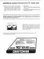
READ AND FOLLOW THE INSTRUCTIONS
THE FRONT OF THE BAND SAW:
APPEARING
ON THEJNSTRUCTION
! D,O_I_JGER
READ AND UNDERSTAND
1, ALWAYS
TIMER
WEAR
WHEN
2. BE POSAT1VE
TEETH
SAFETY
OPERATING
THE
POeRTING
BEFORE
3. ME SURE
BEARINGS
GOGGLES
SAW
THIS
BLADE
DOWNWARD
PER
PROPERLY
ANSI
7.87.1
AT ALL
BEFORE
S, MINIMIZE
BY
NSTALLEO
TOWARD
PROPERLY--
THE
GUIDES
ADJUSTED
FOR YOUR OWN SAFETY:
MANUAL
MACHINE.
iS
OPERATING
MACHINE.
BLADE
TENSION,
BLADE
ARE
'1
OWNER'S
TABLE-AND
BEFORE
THRUST
OPERATING
PLATE ON
KEEPING
6, MAINTAIN
HOLD
OPERATING THIS MACHINE:
INJURY
FIRMLY
7. BE ATTENTIVE
SLOT
IN iNSERT,
STOP
POTENTIAL
FINGERS
CONTROL
BEFORE
OF CONTACT
A SAFE
OF
AGAINST
THE
THE
DISTANCE
AT
ALL
BLADE
TIMES--
TABLE.
TO THIN CUT-OFF
OR JAMMING
IN
REMOVING
WITH
AWA'L
WORKPIECE
JAMMED
PIECES
HITTING
END
SLOT. ALLOW
BLADE
OF
TO
PIECE.
MACHINE
4. ALWAYS
ADJUST
UPPER
GUIDE
SO THAT
IT JUST
CLEARS
_.._
WORKPIECE
f| DIRECT
DRIVE
EJANI:3
SAW
_,÷._
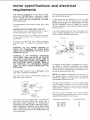
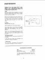
motor speci ications
requirements
This machine is designed to use, and is equipped with, a 1725 RPM motor. It is wired for operation on 110-120 volts, 60 Hz., alternating current.
(TOOL MUST NOT BE CONVERTED TO OPERATE ON 230 VOLT).
For replacement
manual.
motor refer to parts list in this
CONNECTING TO POWER SUPPLY OUTLET
This machine must be grounded while in use to
protect the operator from electric shock.
Plug power cord into a 110-120V properly grounded type outlet protected by a 15-amp. fuse or circuit breaker.
If you are not sure that your outlet is properly
grounded, have it checked by a qualified electrician.
and electrical
This plug requires a mating
ed type outlet as shown.
3-conductor
ground-
If the outlet you are planning
to use for this
power tool is of the two prong type, DO NOT
REMOVE OR ALTER THE GROUNDING
PRONG
IN ANY MANNER.
Use an adapter as shown
below and always connect the grounding lug to a
known ground.
It is recommended
that you have a qualified electrician replace the TWO prong outlet with a properly grounded THREE prong outlet.
GROUND!NG LUG
SCR_:W
\
WARNING:
DO NOT PERMIT
FINGERS
TO
TOUCH THE TERMINALS
OF PLUGS WHEN
iNSTALLING
OR REMOVING THE PLUG TO OR
FROM THE OUTLET.
WARNING:
IF NOT PROPERLY
GROUNDED
THiS POWER TOOL CAN CAUSE AN ELECTRICAL SHOCK PARTICULARLY
WHEN USED IN
DAMP LOCATIONS
CLOSE TO PLUMBING.
BF
AN ELECTRICAL
SHOCK OCCURS THERE IS
THE POTENTIAL OF A SECONDARY
HAZARD
SUCH AS YOUR HANDS CONTACTING
THE
SAW BLADE.
If power cord is worn or cut, or damaged
way, have it replaced immediately.
in any
Your unit is for use on 110-120 volts, and has a
plug that looks like below.
3-PRONG
PLUG
i
\
GROUNDING
PR0i'4G
PROPERLY
GROUNDED
3-PRONGOUTLET
This power tool is equipped with a 3-conductor
cord and grounding
type plug which
has a
grounding
prong,
approved
by Underwriters'
Laboratories and the Canadian Standards Association. The ground conductor
has a green jacket
and is attached to the tool housing at one end
and to the ground prong in the attachment
plug
at the other end.
--
_
RECEPTACLE
ADAPTER
An adapter as illustrated is available for connecting plugs to 2-prong
receptacles.
The green
grounding
lug extending
from the adapter must
be connected to a permanent ground such as to
a properly grounded outlet box.
NOTE: The adapter illustrated
is for use only if
you already have a properly grounded
2-prong
receptacle. Adapter is not allowed in Canada by
the Canadian Electrical Code.
The use of any extension cord will cause some
loss of power. To keep this to a minimum and to
prevent overheating
and motor burn-out, use the
table below to determine the minimum wire size
(A.W.G.) extension cord.
Use only 3 wire extension cords which have 3prong grounding
type plugs and 3-prong receptacles which accept the tools plug.
Extension
Cord Length
Up to 100 Ft.
100 - 200 Ft.
200 - 400 Ft.
Wire Size A.W.G.
16
14
10
contents
CONTENTS
POWER TOOL WARRANTY ....................
2
GENERAL SAFETY iNSTRUCTIONS
POWER TOOLS ..............................
2
ADDITIONAL SAFETY INSTRUCTIONS
FOR BAN D SAW .............................
3
MOTOR SPECIFICATIONS AND ELECTRICAL
REQUIREMENTS .............................
5
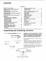
UNPACKING
6
AND CHECKING
CONTENTS
ASSEMBLY
Mounting Band Saw to Workbench ............
Clamping Band Saw to Workbench ............
Installing the Table ...........................
Installing the Blade ..........................
Tensioning the Blade ........................
Tracking the Blade ..........................
Adjusting the Table Square to Blade .........
Adjusting Upper Blade Guide
Assembly ..................................
Adjusting Upper Blade Guides ...............
Adjusting Upper Thrust Bearing .............
Adjusting Lower Blade Guide
Assembly ..................................
unpackin
Adjusting Lower Blade Guides ...............
Drive Belt Tension ..........................
Adjusting Table ..............................
FOR
.....
GETTING TO KNOW YOUR BAND SAW
Tension Adjustment Knob ...................
Cover Knobs ................................
Blade Guides ...............................
Tension Lock Knob .........................
Guide Bar Lock Knob .......................
Table Lock Knobs ...........................
Bevel Scale .................................
On-Off Switch ..............................
BASIC BAND SAW OPERATION
Sawing .....................................
7
8
8
9
10
11
11
15
MAINTENANCE ..............................
Lubrication .................................
RECOMMENDED
.12
12
12
ACCESSORIES
TROUBLESHOOTING
16
16
.............
........................
REPAIR PARTS ..............................
16
17
18
12
NEEDED
_]
,I
'
•
, I,
I"
I.
I'
I1
I"
I,
COMBINATION
I'
I1
l_l_
IILi
I
li
WARNING: FOR YOUR OWN SAFETY, NEVER
CONNECT PLUG TO POWER SOURCE OUTLET
UNTIL ALL ASSEMBLY STEPS ARE COMPLETE,
AND YOU HAVE READ AND UNDERSTAND THE
SAFETY AN D OPERATIONAL INSTRUCTIONS.
'
SQUARE
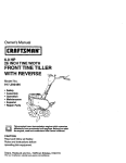
Model 113.244510
in one carton.
Band Saw is shipped
complete
Separate all parts from packing materials
and
check each item with illustration
and "Table of
Loose Parts". Make certain all items are accounted for, before discarding any packing material.
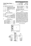
#2 PHILLIPS SCREWDRIVER
MEDIUM SCREWDRIVER
1/2
14
14
14
14
14
14
14
14
and checking contents
TOOLS
I
12
13
13
If any parts are missing,
do not attempt
to
assemble the band saw, plug in the power cord,
or turn the switch on until the missing parts are
obtained and installed correctly.
NCH WRENCH
COMBINATIONSQUAREMUST BETRUE
DRAWLIGHT
LINE ON BOARD
ALONG[HiS EDGE
_,
STRAIGHTEDGEOF
BOARD3/4" THICK
THIS EDGEMUST BE
PERFECTLYSTRAIGHT
SHOULD BE NOGAPOROVERLAPHEREWHEN
SQUAREiS FLIPPEDOVER INDOTTEDPOSITION
nTEM
A
B
C
D
IoTY:
....
TABLE OF LOOSE PARTS
Basic saw assembly ................
Owners Manual ....................
Saw Table assembly ................
Bag Assembly Part #69181
Containing the following parts:
Switch, Key ........................
Nut, Wing 1/4-20 ....................
Screw, Truss Hd. 1t4-20 x 3/4 ........
Washer 17/64 x 5/8 x 1/16 ...........
Wrench, Hex "L" 1!8 ................
Wrench, Hex "L" 3/16 ...............
Washer 17164 x 47/64 x 1116 .........
Indicator, Bevel ....................
Screw, Pan Cross 10-24 x 1/4 ........
Insert, Table .......................
Knob ..............................
1
1
1
1
1
1
1
1
1
2
1
1
1
2
C
assem
ly
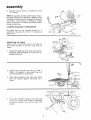
MOUNTRNG BAND SAW TO WORKBENCH
If band saw is to be used in a permanent location, it should be fastened securely to a firm supporting surface such as a workbench.
NOTE: Front two mounting
bolts should
be
inserted from the bottom with washer and nut on
top.
If mounting to a workbench,
holes should be
drilled through supporting
surface of the workbench using dimensions illustrated.
1.
Each leg should be bolted securely using
5/16" diameter machine screws, Iockwashers,
and 5/16" hex nuts (not included).
Screw
length should be 11/2" plus the thickness of
the bench top.
2.
Locate and mark the holes where band saw is
to be mounted.
3.
Drill (4) 3/8"
bench.
through
work-
4.
Place band saw on workbench aligning
in feet with holes drilled in workbench.
holes
5.
Insert all four 5/16" screws and tighten.
diameter
holes
-_
3/8"
6-5/16"
(4) HOLES
I
t______________
!Oq 3/16 ..._________-I_-
An alternate method of mounting
is to fasten
band saw to a mounting board. The board should
be of sufficient size to avoid tipping of saw while
in use. Any good grade of plywood or chipboard
with a 3/4" minimum thickness is recommended.
(Thinner chipboard can break.)
24"
-_
.
Follow instructions
for mounting
to workbench, substituting
a board 18" x 24" minimum size and using 5116 inch flat head
screws, Iockwashers,
and hex nuts (not included). Screw length should be 1!/2" plus
the thickness of the mounting board.
NOTE: For proper
stability,
holes must be
counter sunk so screw heads are flush with the
bottom surface of supporting board.
DIAMETE_R +
18"
MIN.
_J_-
M!N
/
3,,8 " [_IAM[!ER
6-5/16"
__--_!0
13/!6"----_
i4i HOLES
assembly
2.
Securely clamp
"C" clamps.
board
to workbench
using
,,0
NOTE: Supporting
surface where band saw is
mounted
should
be examined
carefully
after
mounting to insure that no movement during use
can result. If any tipping or walking is noted
secure workbench
or supporting
surface before
operating band saw.
CLAMPING
BANDSAW
TO WORKBENCH
The Band Saw can be clamped directly
to a
workbench using two (2) or more "C" clamps on
base of unit.
C
CLAMP
WORKBENCH
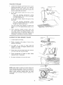
INSTALLING THE TABLE
Apply a coat of automobile
wax to the table top
and inside surfaces
of trunnion
that slide on
frame.
Loosen the guide bar lock knob and position
the upper guide assembly all of the way up.
Tighten lock knob.
1.
.
,
Locate two (2) knobs and two (2) 17/64 x
47/64 x 1/16 washers in loose parts bag, and
the table assembly in loose parts.
Place table assembly onto
with the trunnion
against
frame.
TABLE
ASSEMBLY
band saw frame
mounting
rib in
TRUNNION
SLOTS
4.
_,
CLAMP
Hold table assembly against the frame and
install two (2) table lock knobs and washers
as shown through
the trunnion
slots and
tighten,
TABLE LOCK
KNOBS
\
5.
Locate bevel indicator
and 10-24x1/4
cross hd. screw in loose parts bag.
6.
install bevel indicator and screw
using a phillips screwdriver.
Th,
installed, assembly
ing the Blade."
continues
pan
as shown
on p. 10, "Tension-
_..
t
©
GUIDEBAR
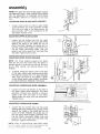
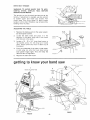
REPLACaNG THE BLADE
KNOB
BLADE
.
2.
UPPERGUIDE
Loosen the guide bar lock knob and position
the upper guide assembly approximately
one
inch above the table and tighten lock knob.
Loosen the two blade guard mounting
screws
and remove the blade guard.
.
.
__'_-..
Loosen the guide bar lock knob and position
the upper guide assembly approximately
two
inches above the table as shown and tighten
the lock knob.
Remove table insert, truss head screw, washer and wing nut from the table (See Assembly, p. 13 - "Adjusting
the Table"). Replace
these parts after the blade is installed, tensioned and tracked.
_,J
5.
Loosen
the two screws
in the
front
--
ASSEMBLY
_
!ll
of the
_'1
blade guides and separate them about 1/8"
6.
Loosen the two screws in the side of the
upper blade guide assembly that secure the
thrust
all of the and
way slide
back. guides
upper bearing
guide assembly
_
and
7.
Tighten all screws.
8.
counterclockwise
and remove cover.
Loosen the three (3)cover
knobs by turning
_U
_o
NOTE: Replace the bandsaw cover after blade is
properly installed, tensioned and tracked.
c0v
_-_
9
_
0
assembly
9.
Loosen the two screws that secure the lower
blade guides and separate them about 1/8".
10.
Loosen
the screw
holding
the lower
blade
guide support and slide support all the way
toward
all
screws. the rear of the saw, and retighten
______...
X
TEN SION WHEEL -,.
BLAOE
WARNING:
TO AVOID
BEING
SCRAPED
SHOULD
BLADE SUDDENLY
UNCOIL, WEAR
SAFETY GOGGLES AND CAREFULLY UNCOIL
THE BLADE HOLDING IT AT ARMS LENGTH.
11. Place the blade over the wheels with the
teeth pointing downward toward the table as
shown. Make sure the blade is in the center
of the rubber tires.
SLOT iN TABLE
WHEEL
IDLER WHEEL
TENSIONING
THE BLADE
TENSION
LOCK
NOTE: Your bandsaw can use only 1/4 inch wide
blades, 56-7t8 inches long. A blade is included
with this saw.
TENSION
ADJUSTING
KNOB
Loosen the tension lock knob (1/4 of a turn
counter-clockwise).
Turn the tension adjusting knob clockwise
until blade has proper
tension. To check blade tension, push thumb
against side of blade between lower wheels.
Blade should move only slightly with moderate pressure. Be careful not to overtension
blade. Retighten tension lock knob.
1.
.
If too much blade tension has been applied,
blades may tend to break more easily and
blade life will be shorter.
If too little blade tension has been applied,
blade may not track easily, may slip on
wheels, or wilt move too easily when checking tension.
.
Turn the upper wheel by hand clockwise
few turns and notice if the blade remains
the approximate center of the tires.
NOTE: Tension
lock
before moving blade.
knob
must
a
in
be tightened
If the blade moves away from the center of
the tires while you are turning the wheels,
the Made is not TRACKING properly.
10
TRACKING
THE BLADE
Loosen the Tension Lock Knob (1/4 of a turn
counter-clockwise)
and turn the tracking
adjustment
set screw slightly with the hex
wrench. (Turning the set screw moves the
tension wheel back and forth.)
1.
If the blade moves
band saw:
,
toward
the front
r.
_
l RACKfi'dG ADJUSTMEN'_
SET SCREW
j
T:NSLON
LOCK KNOB
of the
Turn
the tracking
adjustment
screw
clockwise about !/4 of a turn, as though
you were tightening it.
If the blade
band saw:
moves
toward
the back of the
Turn
the tracking
adjustment
screw
counter clockwise
about 1/4 of a turn as
though you were loosening it.
Turn the screw just enough to cause the
blade to run in the approximate center of all
tires.
,
After adjusting,
tighten
tension
knob and
turn upper wheel by hand clockwise
a few
turns and notice if the blade remains in the
approximate
center of the tires, Readjust if
necessary, until blade is tracking properly.
H
AUGNING
THE TABLE SQUARE TO BLADE
table
C0MBLNA_IONI _
1.
Loosen
lock knobs.
2.
Place a square on the table
blade as illustrated.
3.
Tilt table up or down to align table 90
degrees to blade (0 degree position)
and
tighten lock knobs.
in front
of the
__Z
..... ,_,.-_,__-_,,,,,_,-,__-,_,j
TABLE
4.
LOCK
KNOBS
0
Adjust zero stop set screw using hex wrench
until set screw just touches frame.
5.
Check squareness
of blade
readjustments
if necessary.
6.
Set bevel indicator
to table.
0
Make
to line up with zero.
ZEROSiOP
SEI SCRYW
NOTE: When table is tilted to a bevel angle, the
lower blade guide support should be lowered to
clear the table. After bevel cutting and returning
table to zero position,
always raise the lower
blade guide up to provide maximum support for
the blade.
11
assembly
J
NOTE: The upper and lower blade guides support
the blade and keep it from twisting during operation. An adjustment
is necessary
when blades
are changed, replaced or installed
for the first
time.
ADJUSTING
,Z
,z
UPPER BLADE GUIDE ASSEMBLY
Loosen lower screw on side of upper blade
guide assemb y and slide assembly forward
until the front edge of the blade guides are
approximately
1/32" from the GULLET of the
saw blade. Tighten screw.
1.
,i,
ADJUSTING
GULLET -_
,,..
UPPER BLADE GUIDES
Loosen the two screws that lock the upper
blade guides and press the two guides evenly
against the sides of the blade but do not
pinch the blade. Release the guides and rotate the upper wheel slightly clockwise
moving the blade downward.
Make sure one
guide is not further away from the blade than
the other. Tighten both screws.
1°
ADJUSTING
SAW
UPPER THRUST BEARING
I
,,..,_..__
_
_/32"
NOTE: The thrust bearing supports
the blade
from the rear and will rotate when the blade is
pushed against it while you are cutting. As soon
as you stop cutting,
the bearing should stop
rotating.
To adjust, loosen the upper screw on the side
of the upper blade guide assembly and slide
the bearing forward until it is approximately
1/32" from the back of the blade. Tighten
screw. Rotate upper wheel slightly clockwise
to check clearance. Readjust if necessary.
oli
:@
JPtJ
i
ADJUSTING
.
•
LOWER BLADE GUIDE ASSEMBLY
Loosen the screw (as shown) on the side of
the lower blade guide assembly
and slide
assembly
forward until bearing is approximately 1/32" from the back of the blade.
Blade guides wil! align with this adjustment.
Tighten screw.
ADJUSTING
.
.......
_
BEARING
I
LOWER BLADE GUIDES
Loosen the two screws that lock the lower
blade guides and press the two guides even y
against the sides of the blade but do not
pinch the blade. Release the guides and rotate the upper wheel slightly clockwise
mow
ing the blade downward.
Make sure one
guide is not further away from the blade than
the other. Tighten both screws.
NOTE: After all adjustments
have been
turn the upper wnee! by hand _c!ockwise)
turns to check blade travel an(] clearance.
BLADE
BLADE
GUIDES
made.
a few
12
i
=.
DRIVEBELTTENSION
WARNgNG:TO
AVOQD UNJURY DUE TO ACCiDENTAL
START,
UNPLUG
TOOL
BEFORE
MAKaNG ADJUSTMENTS.
The tension on the drive belt has been set at the
factory. If adjustment
is needed, use hex wrench
to loosen upper and lower cap screws.
Pull
motor away from drive wheel to apply proper
tension to drive belt. Retighten cap screws while
holding motor in place.
ADJUSTING
THE TABLE
1.
Replace the blade guard on the upper assembly and tighten screws.
2.
Locate the table insert and place it in the
opening in the table. Align slot in the insert
with the slot in the table.
3.
Locate a 1/4 - 20 x 3/4" truss head screw, a
flat washer, and a 1/4 - 20 wing nut in loose
parts. Insert screw into hole in table top as
illustrated.
4.
From the underside of the table, install washer and wing nut onto the truss head screw
and tighten finger tight. This will keep the
table flat and in alignment.
5,
BLADE I!li
GUARD
tRUSSHEAD
%_7tt
11[
SCREW "__
WASHERI"'_'_
_
V'aNGNUT //_
Replace the band saw cover.
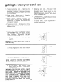
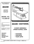
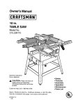
ettin
te know your band saw
TRACKING ADJUSTMFN]
SCREW
1
4
TENSION ADJUSTING KNOB
TENSION
LOCK
FRAME
KNOB
5
J
GUIDE BAR
i
f
LOCK KNOB
2
3
COVER
KNOBS
_ABLE
\
BLADE
l
K
IDES
._S
BLADE
TABLE
INSERT
6
TABLE
LOCK
KNOBS
7
BASE
8
TRUNNION
ON-OFF
SW_TCH
BACK
COVER
FRONT
13
BEVEL
SCALE
getting to know your band saw
1,
Tension
adjusting
knob...
Tightening
the
knob (clockwise) will increase the tension on
the blade, Loosening it (counter clockwise)
will decrease the tension. (Tension lock knob
must be released).
2:
Cover knobs
Secure cover to
tightening all three (3) cover knobs.
3.
frame
by
6.
Blade Guides...Supports
the blade and
keeps it from twisting
during operation. An
adjustment
is necessary
when blades are
changed or replaced.
4. Tension lock knob ... Holds position of the
upper wheel which is set by the tension
adjusting knob.
S.
ON-OFF SWITCH. The On-Off Switch has a
locking feature. THIS FEATURE IS INTENDED TO HELP PREVENT
UNAUTHORIZED
AND
POSSIBLY
HAZARDOUS
USE BY
CHILDREN AND OTHERS.
1.
To turn
switch.
machine
on
NOTE: Key is made of yellow
loose parts bag,
.
3.
insert
plastic;
Insert finger under switch
end of switch out.
To turn machine
OFF...
5. Guide bar lock knob...The
upper blade
guide assembly should just clear the workpiece while cutting. Always adjust the upper
guide assembly and lock the guide bar by
tightening
the blade guide lock knob before
turning on the band saw.
key
into
locate
in
lever and pull
PUSH lever n.
NEVER LEAVE THE MACHINE
UNATTENDED
UNTIL IT HAS COME TO A COMPLETE STOP.
To lock switch in OFF position..,
hold
switch IN with one hand...
REMOVE key
with other hand.
WARNING: FOR YOUR OWN SAFETY, ALWAYS
LOCK THE SWITCH "OFF" WHEN MACHINE IS
NOT IN USE... REMOVE KEY AND KEEP IT IN A
SAFE PLACE...
ALSO ... IN THE EVENT OF A
POWER FAILURE (ALL OF YOUR LIGHTS GO
OUT) TURN SWITCH OFF...
REMOVE THE KEY
AND STORE IT REMOTE
FROM BAND SAW.
THIS WILL PREVENT THE MACHINE
FROM
STARTING
UP AGAIN
WHEN
THE POWER
14
COMES BACK ON,
Table lock knobs ... Loosening knobs allows
the table to be tilted and tightening
knobs
locks the table in place.
7. Tilt (bevel) scale...
Shows
tilted for bevel cutting.
degree
table
is
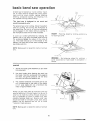
basic band saw operation
A band saw is basically a "curve cutting" machine. It is also used for straight-line cutting operations such as cross cutting, ripping, mitering,
beveling, compound cutting, and resawing. It is
not capable of doing inside cutting.
This band saw is designed
wood aike products only.
to
cut wood
SAW
KERF
W0 R KPi EC:_:
and
For general type scroll cutting, fellow the pattern
lines by pushing and turning the workpiece
at
the same time. Do not try to turn the workpiece
while engaged in the blade without pushing it;
the workpiece could bind or twist the blade.
P,_,]l_RN L [Nti
RIGHT
for cutting
A curve cut is best performed
by keeping the
pattern line in line with the blade while turning
the workpiece before the radius of the curve is
cut. The blade should cut in the middle of the
pattern line (saw kerf) since wood cutting band
saw blades are thin.
- Planning
a curve.
BLADE
ahead by turning
workpiece
W0 R KPi _}C E}
/
NOTE: Blade guard is raised for clarity of picture
only.
--.:z:2:x:
......................
PAl fERN LINE
WRONG
- Not planning ahead for cutting
curve could bind or twist blade if workpiece
forced.
SAWUNG
1.
.
Adjust the upper guide assembly
the workpiece.
to just clear
Use both hands while feeding
the blade. Hold the workpiece
the table. Use gentle pressure.
the work, but allow the blade to
the work into
firmly against
Do not force
cut.
BLADE
.
The smallest diameter circle that can be cut
out is determined
by the width of the blade.
A 114" wide blade will cut a minimum
diameter of approximately
1-1/2".
/
I
Relief cuts are made when an intricate curve (too
small a radius for a ll4-inch blade) is to be cut. A
relief cut is made by cutting through scrap section of workpiece to curve in pattern line, then
carefully backing blade out. Several relief cuts
should be made for intricate curves, then follow
pattern line as sections
are cut off of curve
"relieving"
blade pressure.
NOTE: Blade guard is raised for clarity
only,
of picture
15
i;
maintenance
WARNING:
FOR YOUR OWN SAFETY, TURN
SWITCH
"OFF"
AND REMOVE PLUG FROM
POWER OUTLET BEFORE MAiNTAINiNG
OR
LUBRICATING YOUR BAND SAW.
TIRES
Pitch and sawdust that accumulate
on the tires
should be removed _ith a stiff brush or scraped
off with a piece of wood. Do not use a sharp
knife or any kind of solvent.
When the tires become worn they should be reptaced. When replacing the tires, put a thin layer
of rubber cement on the outside of the wheels
and inside of the tires. Allow to dry, then slide
tires onto wheels aligning
tires inside wheel
edges.
BLACK
GENERAL
Keep your Band Saw clean.
._
6r_EF-N
-
MOTOR
Remove sawdust from the inside frequently.
Do not allow
blade insert,
Clean them
Remover.
pitch to accumulate
on the tabQe,
blade guides, or thrust bearings.
with Craftsman
Gum and Pitch
Apply a thin coat of automobile-type
wax to the
table so the wood slides easily while cutting.
Also apply wax to the inside surfaces
of the
trunnion.
MOTORIELECTRIC AL
Frequently vacuum or blow out any sawdust
the motor.
If the power cord _s worn, cut, or damaged
way, have it replaced immediately.
from
in any
LUBRICATION
All of the BALL BEARINGS are permanently
lubricated. They require no further lubrication.
RECOMMENDED
ACCESSORIES
Item
Miter Gauge ...........................
Blades (56-7/8" length) ..............
Cat. No.
9-24214
See Catalog
The above recommended
accessories are current
and were available at the time this manual was
printed.
16
troub esheetin
WARNING:
FOR YOUR OWN SAFETY, TURN
SWITCH "OFF"
AND REMOVE PLUG FROM
POWER OUTLET BEFORE READJUSTqNG
OR
ALBGN_NG YOUR BAND SAW.
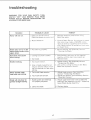
TROUBLE
PROBABLE
Motor will not run.
1. Defective
Defective
REMEDY
CAUSE
On-Off switch.
power or motor cord.
1. Replace defective
Band Saw again.
parts
before
using
2. Motor Defective.
2,
Consult
Sears Service.
Any attempt
to repair
this motor may create a HAZARD
unless
repair is done by a qualified
service technician. Repair service is available
at your nearest Sears Store.
BBade does not run in the
approximate
center of the
upper wheel.
1. Not
!.
Adjust tracking,
see Assembly
"Tracking
the Blade."
Band
when
1. Cutting
Saw slows
cutting.
Bgades
down
breaking.
tracking
properly.
too small
2. Dull
blade.
1. Too
much
1. Stop feeding,
and back up the materi
slightly,
until the band saw speeds up.
2. Replace
blade.
a radius.
tension.
2. Kink in blade caused
by cutting too small a radius or turning the material
too fast when
cutting.
Motor sounds under
load when not cutting.
Blade will not allow for
general straight cutting.
1. Too
much
blade
2. Too
much
belt
Sectio
tension.
" 1. Adjust tension.
See Assembly
"Tensioning
The Blade."
2. Use correct
cutting
technique.
Band Saw Operation
Section.
1. Adjust
section
2. Adjust
"Drive
tension.
sectio_
See Basic
blade tension.
See Assembly
"Tensioning
The Blade."
belt tension.
See Assembly
Section
Belt Tension."
1. Blade guides and bearings
not properly adjusted.
1. Adjust upper and lower blade guides and
bearings. See Assembly section "Adjusting
Upper Blade Guide Assembly."
2. Defective
2. Replace
blade.
17
blade.
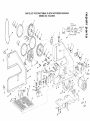
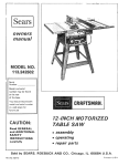
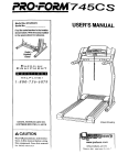
PARTS LIST FOR CRAFTSMAN
10 INCH MOTORIZED
MODEL NO. 113.244510
/
BANDSAW
5
7
/
8
10
11
12
6t
14
34
16
22
18
24
19
63
47
9
55
42
9
41
33
62
27
51
i2
51
j;
29
30
jJJ
6O
//f°
32
Lj /
32
PARTS LiST FOR CRAFTSMAN
10 iNCH MOTORIZED
MODEL NO. 113.244510
ALWAYS
Key
No.
1
2
3
4
5
6
7
8
9
10
11
12
13
14
!5
16
t7
18
19
2O
21
22
23
24
25
26
27
28
29
3O
31
32
33
34
35
36
ORDER
Part
No.
69165
STD315505
69166
69177
69179
69170
69154
69159
STD551025
STD502503
69158
69146
69157
115544
STD600803
62442
60256
69149
69164
STD551208
STD510802
69147
69161
STD541031
STD551131
69178
STD541025
69155
37887
37911
69150
9421626
69151
STD510603
STD551125
60102
BY PART
NO. AND
DESCRIPTION
- NOT
Description
Ring - Retaining 5160
*Bearing - Ball
Ring - Retaining 5000
Tire
Wheel -Idler
Shaft - Upper Wheel
Guide - Wheel
Knob
*Washer 17164x47/64x1/16
*Screw-Set Hex Cup 1/4-20x3/8
Knob
Clamp - Guide Rod
Knob
Lock Washer - Internal
"Screw - Pan Cross 8-32x3/8
Switch - Locking
Switch- Key
Cover - Switch
Relief Strain
*Lockwasher - Int #8
*Screw-Pan Corss 8-32x5/16
Cord - Power
,,Motor
*Nut - Hex 5/16-18
*Lock Washer - 5/16
Trunnion
*Nut Hex v4-20
Indicator Bevel
Wrench Hex "L" 1/8
Wrench Hex "L" 3/16
Foot - Frame
Screw-Soc Cap 5/16-18x! _/_
Frame
Screw-Pan Hd. 6-32x318
Lockwasher - _'_
Screw-Soc Cap t,:_-20xl
BANDSAW
BY KEY NO.
Key
No.
37
38
39
4O
41
42
43
44
45
46
47
48
49
50
51
52
53
54
55
56
57
58
59
6O
61
62
63
64
65
66
67
68
69
Part
No.
69172
60528
69169
69174
69175
STD512507
STD551010
STD511005
69167
69152
STD511003
69163
60529
69171
69153
69173
STD511002
69176
60531
60532
69156
60530
9414920
STD541625
60533
69160
69148
69180
69168
69144
69162
69145
803709
69182
69181
t Any attempt to repair this motor may create a hazard unless repair is done by a qualified
Repair service is available at your nearest Sears store.
Standard
Hardware
Items
- May Be Purchased
Localtv
Description
Spacer
Bearing - Ball
Shaft - Guide Support
Support - Lower Guide
Support - Guide
_Screw-Pan Cross 1/4-20x3/4
'Washer 13/64x1/2x3/64
*Screw-Pan Cross 10-24xV2
Rod - Guide Support
Guard Blade
*Screw-Pan Cross 10-24x3/8
Ring - Retaining
Bearing - Ball
Shaft - Upper Guide
Guide
Support - Upper Guide
*Screw-Pan Hd. 10-24x!/4
Table- Band Saw
Screw-Locking
Set 1/4-20x5/8
Screw-Flat Cross 1/4x20x1
Insert - Table
Screw-Truss Hd. 1/4-20x3/4
Washer 17/64xS/8x1/16
*Nut - Wing t/4-20
Ring, Retaining
Knob
Cover- Frame
Wheel- Drive
Shaft - Wheel
Belt Timing
Pulley Timing Belt
Blade Band Saw (56-7/8" Long)
Connector Wire
Owners Manual (Not Ills.)
Bag Of Loose Parts (Not Ills.)
service technician.
D SAW
A
SERVnCE
Now
Saw
that you have
should
a need
purchased
ever exist
your
lO-lnch
Band
for repair
parts or
service,
simply
contact
any Sears
and most Sears, Roebuck
and Co.
to
provide
visit.
all
pertinent
facts
Service
stores.
when
Center
Be sure
you
call
or
MODEL NO.
113.244510
The
model
number
of your
be found
on a plate at the
10-Inch
Band
Saw will
right-hand
side of the
saw.
WHEN
ORDERING
REPAIR
PARTS,
GIVE THE FOLLOWING
INFORMATION:
HOW TO ORDER
REPAIR PARTS
PART
NUMBER
PART
MODEL
NUMBER
113.244510
ALWAYS
DESCRIPTION
NAME
10-Inch
OF ITEM
Band
Saw
All parts listed may be ordered
from
any Sears
Service
Center
and most
Sears stores.
If the
parts
you need are not stocked
tocally,
your
order will be electronically
transmitted
to a Sears
Repair Parts Distribution
Center for handling.
Sold
Part
No. 69182
by
SEARS,
I_OEBUCK
AND
Form
No,
CO., Chicago,
5P4827-1
IL.
60684
U.S.A.
1 t/8z