1
Ii
Future Reference
_AIRS
MODEL
O.
113.236150
Serial
Number
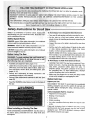
Model and serial number may be
found attached to the right side of
arm housing.
16 INCH
RIABLE
SPEED SCROLL SAW
You should record both model
and serial number in a safe place
for future use.
i ii llllINNI
'
II
................
FOR YOUR
SAFETY:
Read ALL
iNSTRUCTIONS
carefully
...........
,
.........
Sold by SEARS,
Part No_SP5641
, assembly
• operating
repair parts
J
_
ROEBUCK
........................
AND CO., Chicago,
IL. 60684 U.S.A.
SCROLL
SAW
Scroll Saw fails due to a defect in material or workRETURNING:THE CRAFTSMAN SCROLL SAW TO THE
E CENTER/DEPARTMENT
IN THE UNITED
':IS USED IN THE UNITED STATES.
'ights which vary from state to state.
IL: 60195
Safer
Safety is a combination of common sense, staying alert
and knowing how your scroll saw works. Read this man,
ual to understand this saw.
_Safety Signal Words
DANGER: means if the safety information is not followed
someone will be seriously;injured or killed.
WARNING: means if the-safety information isnot followed someone could be seriously injured or killed.
CAUTION: means if the safety information is not followed
someone might be injured.
Before Using The Saw
Assembly and alignment (See pages 7-12)
Learn the:;:::use
and function of the speed control ONOFF knob, bevel: lock knob, blade holders, blade sup,
port, hold down, tension knob, and blade guard. (See
pages14:16)
• Review of the maintenance:meth0ds
page 20)
• Turn saw off and unplug cord before moving the saw.
• Put the saw on a firm level surface where there is
plenty of room for handling and properly supporting the
workpiece.
• Support the saw so the table is level and the saw does
not rock.
= Bolt the saw to the work surface if it tends to slip, walk,
or slide during operations like cutting long heavy
boards, or when using an auxiliary table.
o NEVER STAND ON TOOL. Serious injury could occur
if the tool tips or you accidentally hit the cutting tool. Do
not store anything above or near the tool where anyone might stand on the too! to reach them.
To Avoid Injury or Death from Electrical Shock:
the following steps are: corn pleted.
• Review and Understand at! safety
operating procedures in this manual.
To Avoid Injury from Unexpected Saw Movement:
instructions and
for this saWi:(See
" Read the WARNING tabeJ!Seiow,found_n
the saw.
t_eba_eof
, WARNING
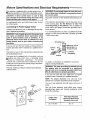
° GROUND THE SAW, This saw has an approved 3 conductor cord and a 3-prong grounding type plug. Use
only:3-wire, grounded outlets rated 120 volts, 15
amperes (amps), The green conductor in the cord is
the grounding wire. :To avoid electrocution, NEVER
connect the green wire to a live terminal.
• Make sure your fingers do not touch the plug's metal
prongs when plugging or unplugging the saw.
Before Each Use:
InsPect your saw,
DISCONNECT THE SAW. To avoid injury from accidental
starting, unplug the saw, turn the switch off and lock out
the switch before changing the setup, removing covers,
guards or blade.
CHECK DAMAGED PARTS. Check for:
- Alignment of moving parts.
• Binding of moving parts.
• Broken parts.
• Stable mounting.
° Any other conditions that may affect the way the saw
works.
When Installing or Moving The Saw
dry indoor _place, prote=_edfrom
well lighted.
rain:i Keep work area
If any part is missing, bent or broken in any way, or an_
electrical parts don't work properly, turn the saw off aria
unplug the saw. REPLACE damaged, missing or failed
parts before using the saw again.
Maintain Tools with Care, Keep the saw clean
for best and safest performance.
Follow instruc-
Dress for safety.
WEAR
YOUR
ns for lubricating.
move adjusting keys and wrenches
turning it on.
from tool before
To avoid injury from jams, slips or thrown pieces:
• Choose the right size and style blade for the material
and the type of cutting you plan to do.
• Use Only Recommended
Accessories.
(See page 21). Consult this owners manual for recommended accessories. Follow the instructions that come
with the accessories. The use of improper accessories may cause risk of injury to person.
• Make sure the blade teeth point downward, toward
the table.
• Make sure the blade tension is properly adjusted.
, Make sure the bevel lock knob is tight and no parts
have excessive play.
• To avoid accidental blade contact, minimize blade
breakage and provide maximum blade support, always
adjust the work and blade guard to just clear the workpiece.
• Keep Work Area Clean. Cluttered areas and benches
invite accidents. Floor must not be slippery.
To avoid burns or other fire damage, never use the saw
._nearflammable liquids, vapors or gases.
!tan Ahead to Protect Your Eyes,
Face and
Hands,
Ears
° To avoid injury from accidental contact with moving
parts, don't do layout, assembly, or setup work on the
saw whi;_eany parts are moving.
• Avoid Accidental Starting.
Make sure switch
"OFF" before plugging saw into a power outlet.
Plan Your Work.
is
• Use The Right Tool. Don't force tool or attachment to
do a job it was not designed to do.
• Use this scroll saw to cut only wood, wood-like products, plastics and non-ferrous metals.
CAUTION: This saw is NOT designed for cutting ferrous metals like iron or steel. When cutting non-ferrous metals (brass, copper and aluminum, etc.),
metal shavings can react with wood dust and start a
fire. To avoid this:
all traces
• Do not wear loose clothing, gloves, neckties or jewelry
(rings, wristwatches). They can get caught and draw
you into moving parts.
° Wear nonslip footwear.
• Tie back long hair.
• Roll long sleeves above the elbow.
° Noise levels vary widely. To avoid possible hearing
damage, wear ear plugs or muffs when using saw for
hours at a time.
° For dusty operations, wear a dust mask along with the
safety goggles.
Inspect Your Workpieceo
, Know Your Saw. Read and understand the owners
manual and labels affixed to the tool. Learn it's application and limitations as well as the specific potential
hazards peculiar to this tool.
°Remove
Any power saw can throw foreign objects into the eyes.
This can cause permanent eye damage. Wear salety
goggles (not glasses) that comply with ANS! Z87.1
(shown on package).
Everyday eyeglasses have only
impact resistant lenses. They are not safety glasses.
Safety goggles are available at Sears Retail Stores.
Glasses or goggles not in compliance with ANSI
Z87.1 could seriously hurt you when they break.
of wood
dust from
on and
round the saw.
Remove all metal shavings from on or around the
I saw before sawing woo d again,
Make sure there are no nails or foreign objects in the part
of the workpiece to be cut.
Use Extra Caution with Large, Very Small or Awkward
Workpieces:
• Never use this too! to finish pieces too small to hold by
hand.
° Use extra supports (tables, saw horses, blocks, etc.)
for any workpieces large enough to tip when not held
down to the table top.
° Never use another person as a substitute for a table
extension, or as additional support for a workpiece or
to help feed, support or pull the workpiece.
• When cutting irregularly shaped workpieces, plan your
work so it will not pinch the blade. A piece of molding,
for example, must lay flat or be held by a fixture or jig
that will not let it twist, rock or slip while being cu_.
° Properly support round material such as dowel rods or
tubingJhey have a tendency to roll during a cut, causing the blade to "bite". To avoid this, always use "V"
block.
• Cut on!y one workpiece at a time.
• Clear everything except the workpiece and related
support devices of_ the table before turning the saw on.
Y_U Wilti Holld the Workpiece
in'i_h,:,_: '
•Donot
handhc :l:pieces s_:ismall thatyour:fingers will ......
i_gula_.:iOse
jigs or fixtures to :hold
ipyo_r_hands away from the blade:
;_e_ati_ns and hand positions where a
sudden slip €_i d cause fingers or hand to move into
ithe blade.
o_:Don,t Overreach. Keep good footing and balance.
° Keep your face and body to one side of the blade, out
oftine with a possible thrown piece if the blade should
break.
Whenever Saw Is Running:
WARNING: Don't let familiarity
(gained from frequent use of your scroll saw) cause a careless
mistake. A careless fraction of a second is
enough to cause a Severe injury,
• Before starting your cut, watCh the saw while it runs. If
it makes an unfamiliar noise or Vibrates excessively,
stop' immediately Turn the saw off:Unplug the:saw:_Do
not restart until findingand correctin gthe problem,
• Keep Children Away. Keep;all:visitors a:saf e distance
i from
:the wo_tSieCei:i
saW.:Make,sure bystanders
are:clear of the
saw and
:
• Don-t; ForCe::T_l::it
better and safer at
its designed rate. Feed the workpiece intothe saw
blade only fast enough to let ,it cut without: bogging
down or binding.=
Before Freeing Any Jammed Materia !,
• Turn switch "OFF"
• Unplug the saw.
• : Wait for all moving parts to:stop.
When backing up the workpiece, the blade may bind
in the kerf (cut),This iiS usually caused by Sawdust
clogging up the kerr. If this happens:
• Turn switch "OFF".
• Unplug the saw.
° Wait for all moving padsto stop.
- With a flat blade screwdriver, turn motor shaft by hand,
by inserting into the slotted end of motor shaft located
at the center of the motor housing. Do this while backing up the workpiece:
Before removing loose pieces from the table, turn
sawoff and wait foraU moving parts to stop:
Before Leaving the Saw:
° Waitforall rnoving parts to stop.
Make Workshop Child-proof. Unplug the saw. Lock
the shop or ONIOFF knob. Store the key away from
children and others not qualified to use the toot.
Motors, Specifications
and Electricat Requirements
This machine is equipped:witha var able speed motor_ It
_ired
for operation on 120V, 60Hz, alternating current.
CAUTION: A direct current motor is used in thisj
saw. Changes to the internal wiring will create a fire I
hazard and may also create a shock hazard.
]
For replacement motor and control board, refer to parts
list in this manual.
Connecting
To Power Supply Outlet
If power cord is worn or cut, or damaged in any way,
have it replaced immediately.
WARNING: if not properly grounded, this power tool
can cause an electrical shock, particularly when
used in damp locations close to plumbing.
If an
electrical shock occurs there is potential of a secondary hazard, such as your hands contacting the
saw blade.
If you are not sure that your outlet, as pictured below, is
properly grounded, have it checked by a qualified electrician.
This plug requires a mating 3-conductor grounded type
outlet as shown.
....
WARNING: Do not permit fingers to touch the terminals of plug when installing or removing the plug to
or from the outlet.
Plug power cord into a 120V properly grounded type outlet.
If the outlet you are planning to use for the power tool is
of the 2-prong type, Do Not Remove Or Alter The
Grounding Prong In Any Manner. Use an adapter as
shown below and always connect the grounding tug to
known ground.
It is recommended that you have a qualified electrician
replace the TWO prong outlet with a properly grounded
THREE prong outlet.
Grounding Lug
Make Sure This Is
3-Prong
Plug
_
Connected to a
Known Ground
,g
Receptacle
Your unit is for use on 120 volts and has a plug that looks
like the illustration below.
This power tool is equipped with a 3-conductor cord and
_[ounding type plug which has a grounding prong
_v
._proved by Underwriters' Laboratories.
The ground
conductor has a green jacket and is attached to the tool
housing at one end and to the ground prong in the attachment plug at the other end.
,
Adapter
An adapter, as illustrated, is available for connecting
plugs to 2-prong receptacles.
The
the adapter must be connected to a permanent
such asgreen
to a properly
outlet from
box.
I ground
WARNING:
groundinggrounded
lug extending
Not all outlet boxes are properly grounded.
If you are not sure that your outlet box is properly
grounded, have it checked by a qualified electrician.
NOTE: The adapter illustrated is for use only if you
already have a properly grounded 2-prong receptacle.
3-Prong
Plug
Properly
Grounded
Outlet
--..,
0
U
Grounding
Prong
The use of any extension cord will cause some loss of
power.
Use only 3-wire extension cords which have 3-prong
grounding type plugs and 3-prong receptacles which
accept the tools plug.
Length of the
Conductor
Wire Sizes Required
(American Wire Gauge
Number) 120V Lines
Up to 100 feet
No. 16
Ke_:::; th_!s|ot::c_t!iby :th_ibiade:_
=
::!:
:::::=:: 5,:Blade Tooth Set:-::the distance:that the edge of th_
work'
_:_wh:iCh
is:
:: : saWblade
tOothisb_ni
(orset
2.:LeadlngEdge:_!_= ...... g .............
p .................:
_.
....... ...........
:
) Outward fromthes,det
:/::.puShed: into theibiade:first:
: :
::::the:b!ade_::: :::::::::
:_:!_,
:
::: .....
....
3_:Sawbtm:fe Path:,- the area0fthework
:
:
p
.....
y
.....6 Trailing
..... Edge;:;
......... the work
.......Piece ed g e last
. cut by the
toward the sawbiade edge:;:::
:4-1:Bevel
' -:the blllty'.....
to slant thetable to make ........
angie cuts.
::
angle cuttir_g operati0nl through the face:of the
board.
-::Contents
:i:Sawblade.
:
,
7 , Wor:kp:iece :- the item :on Whichthe cutting operation is
being performed.
i
....
Mounting the Scroll Saw ............................................. 13
W_rranty Information.... ........................... ...................... 2
Getting to Know Your Scroll Saw ................................. 14
ety Instructions for Scroll Saws :...... i.. ..:i ::..: .. 2
Speed Control/On-OFF Knob ............................... 15
Motor Specs and Electrical Requirements .................. :. 5
Choice of Blade and Speed .................................. 16
Glossary of Terms for Woodworking ... ................. ..... :..:6
Operation ....................................................................
17
Unpacking and Checking Contents ............................... 6
Making
Interior
Cuts
.............................................
19
Assembly and Alignment ............................................... 7
Maintenance
................................................................
20
Setting Table for Horizontal or Bevel Cutting ..........
8
Wiring
Diagram
...........................................................
2I
Aligning the Bevel Indicator .................................... 8
Recommended
Accessories
.......................................
21
Removing and Installing Blades .... ................... ..,._..:.._10
Troubleshooting
...........................................................
21
Adjusting Work Hold-Down Foot. ...................... .,.L.... 12
Repair
Parts
................................................................
22
Dust Blower ..................................................................
12
Service Information ....................................... Back Cover
Blade Guard: ...................................... :......................... 12
Unpacking and Checking Contents ........
Tools Needed
MEDIUM STANDARD SCREWDRIVER
::j_
COMBINATION
MEDIUM PHILLIPS SCREWDRIVER
WARNING: For your own safety never connect plug
to power sou rce outlet until all assembly iStepsare
complete, and you have read and understand the
safety and operating instructions.
IMPORTANT: Never lift this saw by the arm which hotds
the blade or damage will occur to your saw.
Separate all parts from packaging materials and check
each item with illustration and "Table of Loose Parts".
Make certain all items are accounted for before discarding any packaging material.
If any parts are missing, do not attempt to assemble the
Scroll Saw, plug in the power cordor turn the switch on
until the missing parts are obtained and installed correctly.
Table of Loose Parts
Qty
A 16" Scroll Saw (Completely Assembled) .............
B Owner's Manual ..................................................
C Loose Parts Bag containing:
Blade ...................................................................
Hex "T" Handle Wrench ......................................
"L" Shaped Blade Change Rod ...........................
1
1
1
1
1
NOTE: Hardware to mount this scroll saw to a bench or
leg set is NOT supplied. See mounting instructionsfor
recommended hardware size.
Do not lift saw by this arm
Lift
C
Here
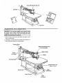
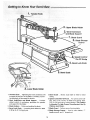
Assembly and alignment ...............................................
WARNING: For your own safety, never connect plug
to power source outlet until all assembly steps are
complete, and you have read and understood the
safety and operating instructions.
1. Lift the saw by the frame and base and place scrolt
saw on work bench.
2. Familiarize yourself with the controls and features of
'_ this scroll saw indicated in the illustration.
Tension Knob
Blade Guard/Hold-Down
Assembly
Holder
Frame
(Lift Here)
de
Arm Bearings _
On/Off Switch and
Speed Control
Table
Lock Knob
Bevel
Bevel
Base
(Lift Here)
ng
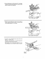
2. A bevel scale is provided under the work table as a
convenient reference for setting the approximate table
angle for bevel cutting.
When greater precision is requiredl make practice cuts
and :adjust the table as necessary:for your require: .... ments.
•
ToAlign
11Lo_n_ttle
the Bevel indiCator
table bevei lock knob an_ move,the:table
until iti is approximately
anale:to the blade,:
L¸
::
perpehdicutar;_ Or:iat a right
Bevel
Lock Knob
J
2_Use a small square to set the table at 90" to the blade.
If there is too much space between the square and the
blade, the table must be adjusted.
3. When the space between the square and the blade is
minimal, tighten the bevel lock knob, The table should
now be approximately 90 ° to the blade,
.......
4. Loosen the screw holding the bevel scale pointer and
adjust to 0 °. Tighten screw.
Remember, the bevel scale is a convenient guide but
should not be relied upon for precision,
Make practice cuts in scrap wood to determine if your
angle settings are correct. Adjust the table as required.
Bevel
Pointer
Knob
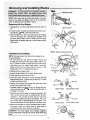
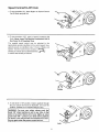
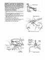
Removing
Pin End Blades
1: UnP!ug=powercord from outlet and Checkthat switch is
ofL
Blade Change Rod
2. Loosen tension on blade by turning tension knob counterclockwise _
about three full turns.
3. Remove blade from the lower blade holder by pushing
down on the upper arm, releasing the blade/pin from
the lower blade holder. Remove blade from the upper
blade holder by slightly lifting up on the blade and pulling forward.
"T" Wrench
Upper
Blade Holder
II
J
NOTE: Teeth pointing downward.
NOTE: Thesaw comes from the factory already setup
for pin end blades.
1. Pin End Blade Set Up: Insert the blade change rod
through the holeabove the upper blade holder. Use
the "T' handle wrench to loosen the h ex socket screw
and clamp from the upper blade holder. Install the
Clamp so that the boss goes into the recess in the
blade holder: The "V" notcheSmust line up.
2. Tighten_he hex socket screw:
3_ Repeat this prOcb_e_i:_n t_heIowgi_blade holder.
:4'iCheck that the tension knob is loose:
Lower
Blade Holder
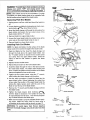
5!instal{ the blade throughlthe insert opening with the
teeth pointing down, Engage the pin into the "V" notch
of :thelower blade:holder:
ecess
6. Pullup on the blade and engage the upper pin in the
notch of the upper blade holder.
%
7. Carefully tighten the blade tension by turning the tension knob clockwise _
until you feel the slack in
the blade is removed.
Blade Clamp
8. Check to see that the pins are properly located in the
slots. Turn the tension knob an additional two full turns
clockwise. This amount of blade tension should do
well for most cutting operations and blades. The number of turns Will be approximately two full turns. This
will vary depending on blade :thiCkness and blade type.
Boss
"V"
Notches
Blade Clamp
9. Make sure the blade is properly installed. Before applyIng power, rotate the motor shaft by hand using a
screwdriver in the motor shaft slot as shown,
injury
objects,
remove the blade
change rod from
and all
tools from the
IWARNING:
To avoid
thrown
saw.
10
Upper Blade Holder
_)
Recess
Lower Blade Holder
• •
I WARNING: To avoid,injury from accidental starting,
l always turn switch' OFF"and unplug power cord
lfrom outlet before removing or,replacing the blade.
ion Knob
i _
OTE: Saw comes set up, for pin end blades. For plain
=end blades, the blade clamp needs to be reinstalled with
the flat surface placed against the blade holder.
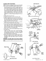
Removing
Plain End Blades
1. Unplug power cord from outlet and check that switch is
off.
Blade Change Rod
2. Loosen tension on blade by turning tension knob counterclockwise _
about three full turns.
3. Insert the blade change rod through the hole above the
blade holder and loosen the hex socket screw of the
blade holder with the "T" wrench.
4. Remove blade from upper blade holder.
5. Loosen the lower blade holder hex socket screw in the
same way as the upper blade ho]der in step 3.
6. Remove blade from lower blade holder.
Installing
Plain End Blades
:NOTE: For plain end blades, the flat surface of the blade
ctamp needs to be positioned against the blade holder.
1. Plain End Blade Set Up: insert the blade change rod
through the hole above the upper blade holder. Use
the "T" handle wrench to loosen the hex socket screw
and clamp from the upper blade holder. Install the
clamp so that the flat surface is against the blade
holder.
"T" Wrencl_
.... 2. Replace the he>(socket screw.
3. Repeat this procedure on the lower blade holder.
4. Install the blade through the hole in the table and into
the lower blade holder. The blade teeth should point
down. Position the blade end at the bottom of the blade
clamp and against the hex socket screw.
l
Blade Change
Rod
Lower
Blade Holder
5. Tighten the hex socket screw, using the "T" wrench,
while holding the blade change rod in position.
Lower Birdie
Holder
6. Use the same procedure to install the blade into the
upper blade holder. Before tightening the socket hex
screw, adjust the position of the upper blade holder by
turning the blade tension knob until the end of the
blade is near the top of the blade holder.
7. Remove the "T" wrench and the blade change rod from
the blade holder.
BRod
8. Tighten the blade tension knob clockwise
until the blade is tensioned. The number of turns will
be approximately two full turns. This will vary depending on blade thickness and blade type.
9. Make sure the blade is properly installed. Before applying power, rotate the motor shaft by hand using a
screwdriver in the motor shaft as shown on page 10.
JWARNING: To avoid injury from thrown objects,
!
PIremove the blade change rod and all tools from the
l saw.
Blade Clamp
Upper Blade Holder
I
Surface
'-_
Blade C!am£
11
Lower B!_de _.o!de_
breakage _iScaused by:the following:
';_tensi_n orunde_tension:
;i:_
iuse::!i_
biade iiife :exiiau st ed;
;rAggressive_
Feeding
:te bygoing too:fast,
of the workpiece
into the
OOT
wARNING:
alwwsturn
fromoutlet
To avoid i'njury from accidental starting,
switch:"OFP
and unplug power cord ;,
before removing or replacing the blade;
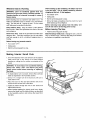
The purpose of the work hold_down foot is to hold the
work against the table so that it :is less likely io liftwith:the
up stroke of the blade, tt should lie flat on the work with
the front prongs straddling the blade.
Height
Adjustment
Knob
Hold-Down
1. The work hold-down foot is attached to the blade guard
wire. The height of the work hold-down foot is adjusted
by loosening the height adjustment knob and moving
the guide post up or down. The work hold-down foot is
adjusted front to back and left-to-right by loosening the
hold-down knob located on the bracket, as illustrated
2. When the table is tilted, the work hold-down foot can
be adjusted by loosening the height adjustment knob
and adiustingthe foot to the same angle as the table.
The work hold-downfoot should always be adjusted as
close to the blade as: possible without touching and
positioned directly on the surface of the workpiece.
Knob
_
Hold-Down
Foot
Adjust
Hold-Down
Foot to
Same Angle
as Table
Dust Blower
The dust blower will direct air to the most effective point
on the cutting line when the hold down is adjusted. No
adjustment is necessary to the blower.
Blade Guard
The blade guard will always be positioned
blade. No adjustment
is necessary,
parallel
to the
i__
iil
--
B/oUSter
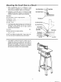
Mounting the Scroll Saw to a Bench
1. When mounting this saw to a workbench a solid
wood bench is preferred over a plywood bench
where noise and vibration will be more noticeable.
6
Lock Washers, 1/4 i.D ...................................................
3
Hex Nuts, 1/4-20 ...........................................................
6
ilrli
,11
Top View
Hex Head Screw
Workbench /
Scroll Saw Base ._
3. A soft foam pad to place between your scroll saw and
workbench is NOT supplied with the saw. However,
we highly recommend the use of such a pad to
reduce noise and vibration.
Hex Head Screw X
Flat Washer -_"\
1/2" Foam Pad. _'N_
Qty.
(Optional)
Soft foam pad such as carpet padding,
I
'__
Side View
Workbench
Do NOT over tighten mounting bolts - leave some cushion in the foam pad for absorbing noise and vibration.
,
i,li,
Qty.
Flat Washers, 1/4 I.D .....................................................
24"x 12" x 1/2". .......................................................
, _ii
] _% •
Hex Head Screw, 1/4-20 x length required .................... 3
Description
,I,L±I_lji,
Scroll Saw Base
2, Hardware to mount this saw to a workbench is Not
supplied with the saw. However, we recommend the
hardware used be not smaller than the following.
Description
i
Ftat Washer
Lock Washer___=
Hex Nut
If you prefer to mount your saw to a leg set, we recommend the leg set for bench top tools which is
available through Sears Retail Stores. The number of
this leg set is 9-22244. This leg set is an optional
accessory and instructions to mount the scroll saw to
this leg set are included in the leg set package.
13
Jam Nut
,
Upper Blade Holder
2. Work Hogd-Down
Blade
Support
7. BladeGuard
8. Blade Storage
Drawer
Speed Control/
On-Off Knol_
4.
Bevel Lock Knob
5. Bevel Scale
3, Lower
Blade Holder
1. Tension Knob ... Tightening the knob (clockwise) will
increase the tension on the blade. Loosening it (counterclockwise) will deCreaSe the tension.
2. Work Hold-Down and Blade Support ... Provides
added control of work-p!ece, protection for operator
and support for the blade_
3. Blade Holders ... Retain and position the blade,
4. Bevel Lock Knob ... Loosening knob allows the table
to tilt up to 45 ° for bevel cuts.
5. Bevel Scale .. Shows angle table is tilted for bevel
cutting.
6. Speed Control!On-Off
Knob ... For speed control setting, refer to the "Choice of Blade and Speed" table.
The On-Off knob has a locking feature, This Feature
Is Intended To Help Prevent Unauthorized Use By
Children And Others.
7. Blade Guard ... Defines area of moving blade.
8. Blade Storage Drawer ... Used to stere blades, "T'
handle wrench, and "L" shaped rod.
14
Speed Control/On-Off
Knob
1.:To turn machine 'On', place fingers on Speed Control/
On-Off Knob and pull out.
2. To turn machine 'OFF', push in Speed Control/On-Off
Knob. Never Leave The Machine Unattended Until It
Has Come To A Complete Stop.
The variable speed control may be adjusted to the
approximate speeds identified on the contro! panel. Suggested speeds are identified under "Choice of Blade and
Speed". Turn the control knob clockwise (,_"_'_)
strokes per minute and counterclockwise
to reduce the strokes per minute.
\,,.
(_"_)
Push
Rotate
3. To lock knob in 'Off' position, install a padlock
the post above the knob as illustrated,
and
padlock.
(Padlock
is not supplied
withthe
through
lock the
saw.)
WARNING:
For your own safety, always push the
knob 'Off' when machine is not in use, Also, in the
event of a power failure (all of your lights go out),
push knob 'Off'. 'Lockout'
your knob with a padlock
as shown. This will prevent the machine from starting up again when the power comes back on.
15
3. Use a blade that will have at least 2 teeth in the matedal at ail times.
4, Use thin, narrow blades for tight radius work, and thi¢_
wide blades for large curves and straight cuts.
Listed below are examples of some blades and their intended uses:
....
Pin and Plain end Biades
:'Teeth/inch
20
15
Width
i, ....
Thickness
ha.__2
.012"
: _110_'.....
12:5
.038"
11.5
10
.053'_
.110"
Speed
:
500-600
!
.0i8"
Application
Tight radius work; 3/32" to 1/8' wood veneer, wood,
bone, fiber, plastics, non-ferrous metals, etc.
.0t 8"
+:+o666'
__
600-1200
Close radius cutting in materials 3/32" to 1/2" thick.
Good for hard and soft wood, bone, horn, plastics, etc.
1200-1700
For hard and soft woods and woodlike products
3/16" to 2".
:,018"
16
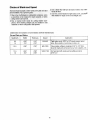
Basic Saw Operations=_lease, read and understand the following items about
bur scroll saw before attempting to use the saw.
1. The saw does not Cut wood by itself. You allow the
saw to cut wood by guiding the wood into the blade
as it moves.
2. The blade teeth cut wood _
on the down stroke.
3. You must guide the wood into the blade slowly
because the teeth of the blade are very small and
they can only remove wood when they are on the
down stroke.
.........
8. To get accurate cuts, be prepared to compensate _or
blade's tendency to follow the wood grain as you are
cutting.
9. This scroll saw is intended to cut wood, wood like
products, plastics and non-ferrous metals.
10. When choosing a blade to use with your scroll saw,
consider the following carefully.
o Very fine, narrow blades should be used to scroll cut
in thin wood 1/4 inch thick or less.
• To cut wood over 1/4 inch thick,
4. There is a learning curve for each person who wants
to use this saw. During that period of time it is
expected that some blades will break until you learn
how to use the saw and receive the greatest benefit
from the blades.
use wider
blades.
o Most blade packages state the size or thickness
of
wood which that blade is intended to cut, and the
radius, size of curve, which can be cut with that
blade.
• Wider blades can't cut curves as tight or small as
thinner blades.
5. Best results are achieved when cutting wood less
than one inch thick.
• Narrower blades work well only on thinner
material.
6. When cutting wood thicker than one inch the user
must guide the wood very, very slowly into the blade
and take extra care not to bend or twist the blade
while cutting in order to maximize blade life.
wood
This saw uses 5 inch long, pin end type, blades only.
See your Sears Retail Store for accessory blades.
Blades wear taster when cutting plywood, which is
very abrasive; when sawing wood which is thicker
than the 7/8 inch blade stroke; and when sawing
hardwood, or when side pressure is placed on the
blade.
7. Teeth on scroll saw blades wear out and as such
must be replaced frequently for best cutting results.
Scroll saw blades generally stay sharp for 1/2 hour to
', 2 hours of cutting.
Before Each Use:
Maintain
inspect your saw.
Keep the saw clean for best and safest performance.
Follow instructions for lubricating.
Disconnect The Saw. To avoid injury from accidental
starting, turn the switch "OFF", unplug the saw before
changing the setup, removing covers, guards or blade.
Tools With Care
Remove Adjusting
before turning it on.
Keys And Wrenches
from
toot
CHECK DAMAGED PARTS. Check for:
To avoid injury from jams, slips or thrown pieces:
o Alignment of moving parts.
• Choose the right size and style blade for the material
and the type of cutting you plan to do.
o Binding of moving parts.
° Broken parts.
o Stable mounting.
o Any other conditions that may affect the way the saw
works.
If any part is missing, bent or broken in any way, or any
electrical parts don't work properly, turn the saw off and
unplug the saw. Replace damaged, missing or failed
arts before using the saw again. Keep Guard In Place
nd in working order
° Use Only Recommended Accessories. (See page
21). Consult this Owner's manual for recommended
accessories. Follow the instructions that come with the
accessories. The use of improper accessories may
cause risk of injury to persons.
° Make sure the blade teeth point downward, toward the
table.
o Make sure the blade tension is properly adjusted.
° Keep Work Area Clean. Cluttered areas and benches
invite accidents. Floor must not be slippery,
To avoid burns or other fire damage, never use the saw
near flammable liquids, vapors or gases.
17
Usel extra caution
awkward workpieces:
With :/large,
very
smal]
or
Neve!_uSethis:t00t t0 finish pieces too small to hold bv
owners
ha a
-
....
Use extra supports (tables, _saw horses, blocks etc.)
for:any workpiece large enough to tip when not held
down to the table top.
o Never use another person as a substitute for a table
extension, or as additional support for a workpiece or
to help feed, support or pull the workpiece
o When cutting irregularly shaped workpieces, plan you r
work so it will not pinch the blade. A piece of molding,
for example, must lay flat or be held by a fixture or jig
that will not let it twist, rock or slip while being cut.
while
Av'oid Accidental Starting.: Make sure switch is "OFF"
before plugging Saw into a power outlet.
Plan your work;
o Use The Right Tool, Don't force tool or attachment to
doa job it Was not designed todo.
,*use this scrolt saw to cut only wood, wood-like products, plastics and non-ferrous metals.
• Properly support round material such as dowel rods or
tubing. They have a tendency to roll during a cut,
causing the blade to "bite". To avoid this, always use a
"V" block,
CAUTION: This saw is NOT designed for cutting ferrous metals like iron or steel. When cutting non-ferrous metals (brass, :copper and aluminum, etc.),
metal shavings can react with wood dust and start a
fire. To avoid this:
° Cut only one workpiece at a time.
° Clear everything except the workpiece and related
support devices off the table before turning the saw on.
Plan the way you will hold the workpiece
finish.
-Remove all traces of wood dust from inside the
Do not hand hold pieces so small that your fingers will go
under the blade guard. Use jigs or fixtures to hold the
work and keep your hands away from the blade.
saw.
• Remove
all traces
of metal
the saw before sawing
wood
dust from
from start to
on or around
again;
Avoid awkward operations and hand positions where a
sudden slip could cause fingers or hand to move Ontothe!
blade.
Dress for safety.
Any power saw can throw foreign objects into the eyes.
This can cause permanent eye damage. Wear safety
Don't Overreach. Keep good footing and balance.
goggles (not glasses) that comply with ANSI Z87.1
(shown on package),
Everyday eyeglasses have only
Keep your face and body to one side of blade, out of line
impact resistant lenses. They are not safety glassesi:: ....with_apossible thrown piece if the blade should break.
Safety goggles: are available :at Sears Retail Stores.
Glasses or goggles not in compliance with ANSi Z87.1
could seriously hurt you when they break_
• Do not wear loose clothing, gloves, neckties or jewelry
(rings, wristwatches). They can get Caught anddraw
you into moving parts,
"* Wear non-slip footwear.
• Tie back long hair.
° Roll long sleeves above the elbow,
° Noise levels vary widely. To avoid possible hearing
damage, wear ear plugs or muffs when using saw for
hours at a time.
• For dusty operations, wear a dust mask along with the
safety goggles.
Inspect your workpiece.
Make sure there are no nails or foreign objects in the part
of the workpiece to be cut.
18
Whenever
Saw Is Running
iWARNING:
Don't let familiarity (gained from fre- I
quent use of your saw) cause a careless mistake. A I
icareless fraction of a second is enough to cause a I
I severe injury.
l
Before starting your cut, watch the saw while it runs. If it
makes an unfamiliar noise or vibrates a lot, stop immediately. Turn the saw off. Unplug the saw. Do not restart
until finding and correcting the problem.
Keep Children Away. Keep all visitors a safe distance
from the saw. Make sure bystanders are clear of the saw
and workpiece.
Don't Force Tool. It will do the job better and safer at its
designed rate. Feed the workpiece into the saw blade
only fast enough to let it cut without bogging down or
binding.
When backing up the workpiece, the blade may bind
in the kerr (cut). This is usually caused by sawdust
clogging up the kerf. If this happens:
* Turn switch "OFF".
- Unplug saw.
o Wait for al! moving parts to stop.
o With a flat blade screwdriver, turn the motor by hand
while backing up the workpiece.
Before removing loose pieces from the table, turn
saw off and wait for all moving parts to stop.
Before Leaving The Saw:
°
Before freeing any jammed material:
• Turn switch "OFF".
o Unplug saw.
• Wait for al! moving parts to stop.
Making
interior
Scroll
Wait for all moving parts to stop.
Make Workshop Child-proof.
Unplug the saw. Lock the
shop or ON/OFF knob, Store the key away from children
and others not qualified to use the tool.
Cuts
1. One of the features of this saw is that it can be used to
make scroll cuts on the interior of a board without
breaking or cutting into the outline or perimeter of the
board.
WARNING: To avoid injury from accidental starting,
always turn switch "OFF" and remove plug from
power source outlet before removing or replacing
the blade.
2, To make interior cuts in a board, remove the scroll saw
blade as explained in the Assembly section,
3. Drill a 1/4" or larger hole in the board you wil! use to
make interior cuts.
4. Place the board on the saw table with the hole in the
board over the access hole in the table.
5. Install the blade through the hole in the board and
adjust blade tension.
6. When finished making the interior scroll cuts, simply
remove the blade from the blade holders, as described
in the Assembly section, and remove the board from
the table.
19
pastewax
onthe wo_k:tabte will
cut _to'glide:smooth y across the
i
The motor bearings are permanently lubricated
require no further lubrication,
and
D0not attempt to oil the motor bearings or service the
m0t0rinternalpartsi
i
WARNING:
power
cord is worm,
cut or dam- i
aged
inany ifthe
way, have
it replaced
immediately.
t WARNING: To avoid fire or electrocution, reassem- i
I bie electric parts with only approved service parts._
[Reassemble exactly as originally assembled.
|
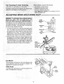
Arm Bearings
Lubricate the arm bearings after 10 _ours of use. Re-oil
after every 50 hours of use or whenever there is a squeak
coming from the bearings_
1. Turn saw on its side.
_
2_Squirt a generous amount 0f SAE 30 oil around the
-::shaft end and bronze bearing._
3_ Let tl_e:oil soak inoVernight in this condition.
4;Next day repeat the above procedure for::the opposite
with
this
saw
are
designed
to give long service life. When one or both
brushes become shorter than 1/4", replace both brushes.
1. Remove
driver.
NOTE:
against
2. Install
the brush cap
The
brushes
using
are spring
a 1/4" flat blade
screw-
loaded and may push
the brush cap as it releases.
the new brush
assembly
and reinstall
the brush
cap.
3. Use the cap to push the spring and brass end of the
assembly into the rectangular
hole as the cap is tightened. Be sure that the brush cap is fully seated in the
\
\,
Brush
brush hoider.
4. Repeat the procedure
for the ether brush.
20
Cap
Brush
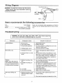
Wiring Diagram
...........
/ARNING: To avoid fire or shock, use only recom_ended service parts and reassemble exactly as
[originally assembled.
_J
Sears recommends
the following accessories
Item
Sears Number
Leg Set ...............................................................
9-22244
Blades ....................... See Sears Retail Store for 5" long
Plain End/Pin End blades
Troubleshooting
t
L
Sears may recommend other accessories not listed in
manual, See your nearest Sears Store for other accessories.
..............................................
power
sourceForoutlet
troubleshooting
your"OFF",
scroll saw.
WARNING:
yourbefore
own safety,
turn switch
and remove
PROBLEM
PROBABLE CAUSE
REMEDY SCHEDULED
........................
Breaking B'iades,
1. Wrong tension
2. Over working blade.
3. Wrong btade application.
4. Twisting blade in wood.
Motor will not run.
1, Damaged cord or plug.
2, Damaged motor or control
board.
Vibration
NOTE: There will always be
some vibration present when
the saw is running because of
the blade and arm movement,
1, Improper mounting of the
saw.
2. Unsuitable mounting surface.
3. Loose table
4. Loose motor mounting.
Motor stops during cuts
plug from I
1: Aggressive feeding causes
Current Protector to shut
motor off.
' "i
1. Adjust blade tension.
2. Reduce feed rate.
3. Use narrow blades for cutting thin wood, wide
blades for thicker wood.
4. Avoid side pressure on blade.
1. Replace damaged parts before using saw
again.
2. Consult Sears Service. Any attempt to repair
this motor or control board may create a HAZARD unless repair is done by a qualified ser_
vice technician. Repair service is available at
your nearest Sears Store.
1. See mounting instructions in this manual for
proper mounting technique.
2. The heavier your workbench is, the less vibration will occur, A plywood workbench wilt not
be as good a work surface as the same size
solid lumber. Use common sense in choosing
a mounting surface.
3. Tighten table lock knob.
4. Tighten motor mounting screws,
1. Turn machine "OFF" and then back "ON" to
continue cutting.
2. Slow down the feed rate ot material into blade.
21
48
J
J
51
J
13
Po
P_
12
15
_10
"
14
11
1S
/I
16
4O
3O
18
22
\
39
32
10
20
23
21
'\
38
11
24
27
37
1
10
28
25
19
10
F
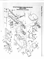
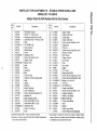
PARTS LIST FOR CRAFTSMAN
MODEL
Always
t',.3
O3
Key
No.
Part No.
1
2
3
4
5
6
7
8
9
10
11
12
13
14
15
16
!7
18
19
20
2!
22
23
24
25
26
27
28
29
3O
3t
32
820733
820333
822426-1
820376-2
821673
813249-131
821701
821708
821707
STD852005
821389
821702
STD851006
821697
820322
820324
822428
821712
821985
821675
821720
819293
821719
821672
817450-5
821722
821677
821151-1
820249-1
STD852006
821683
82t697q
Order
16"
, RIABLE
SPEED
SCROLL
SAW
NO. 113.236150
By Part Number-Not
Description
Rod, Blade Change
Wrench, "T" Handle, 4ram
Housing (includes Key #4 & 41)
Screw Pan Hd Ty "TT" M4 x 0,7-28
Table
Pin, Roll M5 x 25
Screw, Support
Guide, Drawer
Drawer
Lockwasher, M5
Screw, Pan Hd M5 x 0,8-8
Support, Scale
* Washer, 6mm
Knob
Brush
Cap, Brush
o Motor
Cord with Plug
Housing, Control (includes label)
Knob
Gasket
Grommet
Board, Controller
Cover, Switch Box
Screw, Pan Hd Self Tap M4 x 18
indicator, Tilt
Base (Includes Labels)
Screw Hex Hd M5 x 0.8-15
Screw Hex Hd M6 x 1.0-20
* Lockwasher, M6
Support, Hold Down
Knob
Standard hardware item - may be purchased locally.
t Stock item - may be secured through the Hardware department
of most Sears Retail Stores
Key l
No. i
33
34
35
36
37
38
39
4O
41
42
43
44
45
46
47
48
49
5O
51
52
53
54
55
56
57
58
59
6o
61
62
63
1
i
1
1
i
I
I
t
i
1
!
t
i
I
I
I
I
I
I
I
I
i
i
I
I
t
1
1
l
{
By Key Number
Part No.
821690
821692
821693
821691
818471-6
821689
821716
820379-1
821717
821704
816018
816017
821675-1
821666
66061
821668
818468
818469
817450-1
46-58600-3
821706
813249-127
820317
818471
821709
820314
9-26877
820316
819248-1
8217O3
820315
SP5641
Description
Support, Plate
Spring, Hold Down
Guard, Blade
Clamp, Hold Down
Screw, Hex Soc Set,M5 x 0.8-5
Support Bar
Plate Clip
Screw, Hex Soc Cap, M5 x 0.8-8
Bearing,
Flanged
Bolt, Tension
Wedge, Tension
Nut, Tension
Knob
Arm, Upper
Spring
Arm, Lower
Bearing, Ball 625ZZ
Screw, Hex Soc Cap, M5 x 0.8-16
Screw, Pan Hd Serf Tap M4 x 16-8
* Washer, 4.2 x 10 x 0.9
Link, Arm
Pin, Roll M5 x 14
Clamp, Lower Blade
Screw, Hex Soc Set, M6 x 1.0-6
Coupling, Eccentric
Holder, Lower Blade
t Blade, Scroll Saw
Clamp, Upper Blade
Hose
Bellows
Holder, Upper Blade
Owner's Manual (Not Illustrated)
;-A_'attempt
to repair this motor may create a hazard unless
repair is done by a qualified service technician. Repair service
is available at your nearest Sears store.
113.236150
your owner's manual for future reference
packed with your scroll saw. The instructions and illustrations shown on
blades.
scroll saw owner's manual for safety instructions and proper use of the scroll saw.
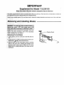
rBlades
IWARNING :_To avoid i_iju_:from accidental starting, i
lahNays 1urn switch _:,!OFF and :unplug power cord
Ifrom_:outlet
before removing or replacing the blade, I
I
NOTE: Saw comes Set :uplfor pin end blades, tf you are
going:to use plain end blades, refer to the instructions
under:_'installingPlain End Blades".
Removing
Pin End Blades
:1;,Unplug power cord from outlet and check that switch is
0ffii_....
2_Loosen tension on blade by turning tension knob countemlockwise _
about three full turns.
3, Remove-blade ftorn :the iiower Blade holder by pushing
down on the upper arm, releasing the blade!pin from
the lower blade holder_: Remove blade from the upper
btade holdei_by slightly;lifting, up on tt_e blade and pulling forward,
Knob
Installing
Pin End Blades
Blade Change Rod
NOTE: The saw come s from the factory already set up
for pin end blades.
4i, Pin End Blade Set Up: Insert the blade change rod
through the hole above the upper blade holder, Use
the "T" handle wrench to loosen the hex socket screw
and clamp from the upper blade holder, Install the
clamp so that the thick boss goes into the recess in the
blade holder. The "V" notches must line up.
2. Tighten the hex socket screw,
3. Repeat: this procedure on the lower blade holder.
4. Check that the tension knob is loose.
Upper
Blade Holder
5. Install the blade through the insert opening with the
teeth pointing down. Engage the pin ir_to the "V" notch
of the lower blade holder.
\
NOTE: Teeth pointing downward.
6. Pull up on the blade and engage the upper pin in the
"V" notch of the upper blade holder.
7. Carefully tighten the blade tension by turning the tension knob clockwise _
until you feel the slack in
the blade is removed.
8, Check to see that the pins are properly located in the
slots, Turn the tension knob an additional two full turns
clockwise. This amount of blade tension should do
well for most cutting operations and blades. The number of turns will be approximately two full turns. This
will vary depending on blade thickness and blade type.
9. Make sure the blade is properly installed, Before apply-'_ ing power, rotate the motor shaft by hand using a
screwdriver in t:he motor shaft slot as shown,
WARNING: To avoid injury from thrown objects,[
remove the blade change rod and all toots from the[
saw.
Thin
Boss
Blade Change
Rod
Lower
Blade Holder
t
Notches
Blade
Holder
Blade
"T" Wrenct
Blade
Clamp
Thick
,Boss
Clamp_
thick Boss
Notches
Upper Blade Holder
Lower Blade Holder
Holder
Knob
tel:clockwise _
about three full turns.
3, Insert the blade change rod through the hole above the
blade holder and loosen the hex socket screw of the
blade holder with the "T" wrench.
Z
Blade Change Rod
4!. Remove blade from upper blade holder.
5i: Loosen th:e lower blade holder he× socket :screw in the
sarnewayaS the upper blade holder in step 3.
61 Remove blade from lower blade holder.
"T" Wrench
Upper
Blade Holder
\.
NOTE: Teeth pointing downward.
Note: Teeth
Pointing
Blade
Holder
Hex Socket
Screw
....
T":Wrencl_
i
::
:Blad_
Chang_.:-,
Rod ::!:::::
:
::
=::
:
___lower
Blade Holder
Blade Change Rod
Installing
Plain End B|ades ..................
Blade Change Rod
NOTE: For plain end blades, the thin boss of the blade
_.l_mp needs to be positioned against the blade holder.
Plain End Blade Set Up: Insert the blade change rod
through the hole above the upper blade holder. Use
the "T" handle wrench to loosen the hex socket screw
and clamp from the upper blade holder. Install the
clamp so that the thin boss is against the blade holder,
and the beveled edge is in the corner of the blade
holder. The thin boss side of the blade clamp can be
identified by a circular impression placed on the surface.
!
Upper
Blade Holder
\
2. Replace the hex socket screw.
NOTE: Teeth pointing downward.
3. Repeat this procedure on the lower blade holder.
4. Install the blade through the hole in the table and into
the lower blade holder. The blade teeth should point
down. Position the blade end at the bottom of the blade
clamp and against the he× socket screw.
5. Tighten the hex socket screw, using the "T" wrench,
while holding the blade change rod in position.
6. Use the same procedure to install the blade into the
upper blade holder. Before tightening the socket hex
screw, adjust the position of the upper blade holder by
turning the blade tension knob until the end of the
blade is near the top of the blade holder.
7. Remove the "T' wrench and the blade change rod from
Lower
8lade Holder
._._the blade hotder.
Tighten the blade tension knob clockwise
until the blade is tensioned. The number of turns will
be approximately two full turns. This wil! vary depending on blade thickness and blade type.
Note: Teeth
Pointing Down _
Holder
9, Make sure the blade is properly installed. Before applying power, rotate the motor shaft by hand using a
screwdriver in the motor shaft as shown on the previous page.
WARNING:
To avoid
injury from
thrown
Blade
Hsx Socket
Screw
objects,
remove the blade change rod and all tools from the
saw.
Blade Clamp
Beveled Edge
Circular ImiDression
Blade Clam_
/
t (_
_i_}B_l_d:
r
Beveled
Edge
Thin
Btade
Holder
Impression
Boss
Upper Blade Holder
Form No. SP5766
Circular
Lower Blade Hotder
Printed in U.S.A. 7:,'94
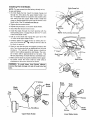
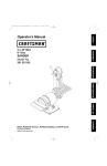
18 iNCH VARIABLE
SPEED SCROLL SAW
SERVICE
Now that you have purchased your scroll saw, should a need
ever exist for repair parts or service, simply contact any Sears
Service Center and most Sears, Roebuck and Co. stores, Be
sure to provide all pertinent facts when you call or visit.
MODEL NO.
113.236150
The model number of your scroll saw will be found attached to
the right side of the arm housing.
HOW TO ORDER
REPAIR PARTS
WHEN ORDERING REPAIR PARTS, ALWAYS GIVE THE FOLLOWING INFORMATION:
PART NUMBER
PART DESCRIPTION
MODEL NUMBER
113.236t50
NAME OF ITEM
t6 INCH VARIABLE
SPEED SCROLL SAW
All parts listed may be ordered from any Sears Service Center
and most Sears stores. If the parts you need are not stocked
locally, your order will be electronically
transmitted
Repair Parts Distribution Center for handling.
4p_...
i
iiiiiiiiiiiii
i
Sold
iiii
_
by SEARS,
Part No. SP5641
_
.....................
ROEBUCK
iiii
AND
CO., Chicago,
Form No. SP5641
i,
J
ii
i
i¸111111111/i
/11
II. 60684
to a Sears
ii
ii
,
iii
U.S.A.
4194