1
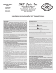
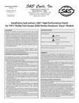
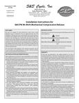
3-10-08
S&S Cycle, Inc
Copyright © 2008
14025 Cty Hwy G PO Box 215
Viola, Wisconsin 54664
Instruction 106-2738
by S&S® Cycle, Inc.
®
.
Phone: 608-627-1497 • Fax: 608-627-1488
All rights reserved.
Printed in the U.S.A.
Technical Service Phone: 608-627-TECH (8324)
Technical Service Email: [email protected]
Website: www.sscycle.com
TÜV Installation Guide, S&S® T124 CLVFI Engine
IMPORTANT NOTICE:
DISCLAIMER:
S&S parts are designed for high performance, off road, racing applications
and are intended for the very experienced rider only. The installation of S&S
parts may void or adversely affect your factory warranty. In addition such
installation and use may violate certain federal, state, and local laws, rules
and ordinances as well as other laws when used on motor vehicles used on
public highways, especially in states where pollution laws may apply. Always
check federal, state, and local laws before modifying your motorcycle. It is
the sole and exclusive responsibility of the user to determine the suitability
of the product for his or her use, and the user shall assume all legal, personal
injury risk and liability and all other obligations, duties, and risks associated
therewith.
Statements in this instruction sheet preceded by the following words are of
special significance.
WARNING
Means there is the possibility of injury to yourself or others.
CAUTION
Means there is the possibility of damage to the part or motorcycle.
NOTE
Other information of particular importance has been placed in italic type.
S&S recommends you take special notice of these items.
The words Harley®, Harley-Davidson®, H-D®, Sportster®, Evolution®, and all
H-D part numbers and model designations are used in reference only. S&S
Cycle is not associated with Harley-Davidson, Inc.
WARRANTY:
All S&S parts are guaranteed to the original purchaser to be free of
manufacturing defects in materials and workmanship for a period of twelve
(12) months from the date of purchase. Merchandise that fails to conform to
these conditions will be repaired or replaced at S&S’s option if the parts are
returned to us by the purchaser within the 12 month warranty period or within
10 days thereafter.
In the event warranty service is required, the original purchaser must call or
write S&S immediately with the problem. Some problems can be rectified by
a telephone call and need no further course of action.
A part that is suspect of being defective must not be replaced by a Dealer
without prior authorization from S&S. If it is deemed necessary for S&S to
make an evaluation to determine whether the part was defective, a return
authorization number must be obtained from S&S. The parts must be packaged
properly so as to not cause further damage and be returned prepaid to S&S
with a copy of the original invoice of purchase and a detailed letter outlining
the nature of the problem, how the part was used and the circumstances at
the time of failure. If after an evaluation has been made by S&S and the part
was found to be defective, repair, replacement or refund will be granted.
SAFE INSTALLATION AND OPERATION RULES:
Before installing your new S&S part it is your responsibility to read and follow
the installation and maintenance procedures in these instructions and follow
the basic rules below for your personal safety.
Gasoline is extremely flammable and explosive under certain conditions
and toxic when breathed. Do not smoke. Perform installation in a well
ventilated area away from open flames or sparks.
If motorcycle has been running, wait until engine and exhaust pipes
have cooled down to avoid getting burned before performing any
installation steps.
Before performing any installation steps disconnect battery to eliminate
potential sparks and inadvertent engagement of starter while working
on electrical components.
Read instructions thoroughly and carefully so all procedures are
completely understood before performing any installation steps.
Contact S&S with any questions you may have if any steps are unclear or
any abnormalities occur during installation or operation of motorcycle
with a S&S part on it.
Consult an appropriate service manual for your motorcycle for correct
disassembly and reassembly procedures for any parts that need to be
removed to facilitate installation.
Use good judgment when performing installation and operating
motorcycle. Good judgment begins with a clear head. Don’t let
alcohol, drugs or fatigue impair your judgment. Start installation
when you are fresh.
Be sure all federal, state and local laws are obeyed with the installation.
For optimum performance and safety and to minimize potential
damage to carb or other components, use all mounting hardware that is
provided and follow all installation instructions.
Motorcycle exhaust fumes are toxic and poisonous and must not be
breathed. Run motorcycle in a well ventilated area where fumes can
dissipate.
••
••
••
••
••
ADDITIONAL WARRANTY PROVISIONS:
(1) S&S shall have no obligation in the event an S&S part is modified by any
other person or organization.
(2) S&S shall have no obligation if an S&S part becomes defective in whole or in
part as a result of improper installation, improper maintenance, improper use,
abnormal operation, or any other misuse or mistreatment of the S&S part.
(3) S&S shall not be liable for any consequential or incidental damages
resulting from the failure of an S&S part, the breach of any warranties, the
failure to deliver, delay in delivery, delivery in non-conforming condition, or
for any other breach of contract or duty between S&S and a customer.
(4) S&S parts are designed exclusively for use in Harley-Davidson® and other
American v-twin motorcycles. S&S shall have no warranty or liability obligation
if an S&S part is used in any other application.
••
••
••
••
1
INSTALLATION OVERVIEW
This S&S® T124 Engine has been approved by the TÜV to meet exhaust and noise emissions in 2002-2006 touring motorcycles. Included with your
engine you will find additional instructions for installing specific parts. This installation guide will list the order these parts are installed and includes
additional information that is specific to the TÜV approved engine.
Installation Notes
S&S Engines include instruction sheets for individual components. Most instructions apply to all S&S Engines. In the following instances, however,
components or procedures supplied with and described for S&S TÜV approved engines are different from those for other S&S Engines.
A. The camshaft supplied in S&S TÜV T124 Engines is of proprietary S&S design. This camshaft has been designed to allow the engine to meet exhaust
emission standards. Substitution of a camshaft with different specifications is not permitted and would be in violation of regulations.
B. The fuel injection system supplied with S&S TÜV T124 Engines can not be adjusted. The tuning instructions described in S&S VFI Module and Pro Tune
II Software Instruction Sheet do not apply to systems supplied with S&S TÜV T124 Engines.
C. Speedometer recalibration will be required on 2004-2006 motorcycles. This can be completed by following the instructions at the end of this guide.
D. The wiring harness on 2006 models will have to be modified following the steps in this installation guide for proper installation.
E. Removing the noise baffles from the air cleaner assembly or manifold is illegal and will cause improper operation of the engine which will result in
engine damage not covered under warranty.
INSTALLATION INSTRUCTIONS
This S&S T124 Engine has been manufactured, assembled, and calibrated by S&S Cycle, Inc. Before proceeding, verify that this engine fulfills the
requirements for your motorcycle. Installing an S&S engine into a motorcycle requires specialized knowledge, skills, and tools. For this reason
installation should be performed by a professional mechanic.
WARNING
••Improper installation of engine or related components could result in injury or death to the operator and/or passenger and damage to
the motorcycle.
••To protect against shock and accidental start-up of the engine, disconnect the negative battery cable. Inadequate observation of safety
precautions could result in serious injury or death.
A. Engine Installation
1. Install engine following the instructions provided in instruction 51-1160 (S&S T124 and T124V Engine Assembly).
2. Install the oil lines following the instructions provided in instruction 51-1160 (S&S T124 and T124V Engine Assembly).
3. Connect throttles cables to throttle body. Refer to the appropriate Harley-Davidson® service manual to connect and adjust the cables.
WARNING
Incorrect cable adjustment may cause throttle to stick open, causing loss of control of motorcycle, serious injury or death.
B. Install Compression Release Wiring Harness
1. Follow step “C” of instruction 51-1115 (S&S 90-4915 Electric Compression Release) to install the wiring harness for the compression releases.
C. Stock Module Removal
NOTE: Harley-Davidson® refers to their module as the ECM (Electronic Control Module). S&S refers to the module as the ECU (Electronic Control Unit).
1. Refer to the appropriate Harley-Davidson® service manual to locate and then access the stock ECM.
2. Remove and save the stock module mounting screws.
3. To remove the 36-position connector (Delphi®), push down on the locking tab located in the center of the connector. Then pull the
connector straight out using an easy rocking motion. See Picture 1.
Picture 1
2
D. S&S® VFI Module preparation and Installation
1. Plug Cover. See Picture 2.
Picture 2
2. The VFI module uses a cover to protect the module's USB tuning access connector from the elements. Packaged separately you will find the
cover, an O-ring, and mounting screws.
3. Place an O-ring in the groove in the ECU as shown in Picture 1. Tighten the two screws to 2-4 in-lbs in the VFI module cover. The plug cover
must be in place whenever the module is not connected to a remote computer for tuning.
CAUTION
Do not over tighten retaining screws or you can damage the ECU. Torque retaining screws to 2-4 in-lbs.
NOTE: Delphi® and Magneti Marelli® style S&S® replacement modules are direct stock replacement units.
E. Install Module on Motorcycle
1. Double check the negative battery cable to be sure it is disconnected. Installing the module with the system powered up could cause the
motorcycle to run poorly or not at all.
2. Push the 36-position connector straight onto end of the VFI module until the connector lock clicks into place.
3. Install the ECU in the same location as the stock ECM, using the original mounting screws.
CAUTION
S&S recommends that you position the main connector of the VFI Module in its stock location for maximum protection against the
elements.
F. Make Throttle Body to Harness Connections
1. On 2002-2005 motorcycles the throttle body is a direct plug in to the factory harness.
2. On 2006 motorcycles see instructions on page 8, 2006 Throttle Body Connections.
G. Install oxygen sensors and harness
1. Follow instructions provided in instruction 51-1203 (Closed Loop Fuel Injection for Delphi® Style S&S® Replacement Module).
H. Final assembly and checks.
1. Check fuel line routing and connections.
2. Test throttle to ensure it opens and closes freely. Turn handlebars to extreme left and open and close throttle, and then turn bars to extreme
right and repeat. Throttle must snap closed in all positions.
3. Reassemble any remaining components.
4. Reconnect battery
5. Fill gas tank.
6. Cycle key and check fuel line connections for leaks.
I. Engine Break-in
1. Follow the break-in instructions found in instruction 51-1160 (S&S T124 and T124V Engine Assembly) to break-in the engine.
CAUTION
Failure to break-in engine according to correct procedure may result in serious damage to engine that is not repairable under warranty.
3
SPEEDOMETER CALIBRATION
Due to differences in 2004-2006 motorcycles the wheel speed gear factor calibration will need to be changed to get the correct speedometer
reading. Changing the wheel speed gear factor will require installing the included Pro Tune II software on a PC and connecting it to a motorcycle.
A. Pro Tune II Software Installation
To install Pro Tune II for the first time or to upgrade Pro Tune II, perform the following:
1. Close all applications, especially any S&S Cycle programs that are currently running.
2. Insert the Pro Tune II installation CD into your CD or DVD drive. After a few moments the Pro Tune II Software Manager should appear on
your screen and you can skip to step 5. If this doesn’t happen automatically, proceed with steps 3 and 4.
3. From the Start menu of your computer, select Run.
4. In the box marked Open: type d:\setup.exe and press Enter or click OK. Most PCs have the CD-ROM drive letter ‘d’. Replace this with the
appropriate letter if your CD drive is installed differently.
5. The Pro Tune II Setup Wizard will appear on your screen. Select Next to continue the installation, or select Cancel to exit the installation.
6. If you are installing Pro Tune II on a PC that does not already have a copy of the software, or has an older version of ProTune II - click the
button marked Install. The window below to the right will appear.
4
7. Windows Vista® users may have the following warning appear during the USB driver installation. Select Install this driver software
anyway.
8. The Pro Tune II installation is complete. Select Finish to exit the Setup Wizard.
After the installation, the Pro Tune II program icon will appear on your desktop. Double-click this icon to start Pro Tune II. You can also find Pro Tune
II in your Programs menu under the program group ‘S&S Cycle’.
B. Connecting to the ECU
1. Install the ECU following instructions on page 2.
2. Connect the USB cable from the ECU to any USB connector on your computer.
3. Launch Pro Tune II. When there is no ECU communicating with the PC, the communications status box at the bottom-right corner of the
screen will flash between blue and black and alternate between the messages No ECU on COM1:, Checking COM1:, No ECU on USB, and
Checking USB.
5
4. Powering the ECU and installing USB drivers.
a. Switch the motorcycle ignition key to the ignition ON position. Switch the engine kill switch to the RUN position. This will power the
ECU.
b. Delphi® style only - Windows® will detect the new device, which will require a driver to be installed.
NOTE: Computers running Windows Vista® operating system will automatically install the USB driver during the ProTune II software installation.
Windows, 2000®, XP®, I. Windows will open the Found New Hardware Wizard - Select "No, not this time" and click "Next". Depending on you computer’s
settings, this window may not appear.
II. Select Install the software automatically and click Next. You may get a “Hardware Installation” warning. Click Continue
Anyway.
Ill. Click Finish to complete the installation.
6
5. The communications status box should illuminate green to show that an ECU is connected and communicating with the PC software.
The communications status box shows the ECU model number (55-5029A in the example above) and the ECU software version (C281 in the
example above). The box to the left also shows the serial number of the ECU (00023791 in the example above). This information may be required
for customer support.
If you cannot establish a connection with your ECU:
Please consult the complete Pro Tune II manual. A shortcut to the manual was installed on your desktop during the ProTune II installation. It can
also be found in the Technical section of the www.sscycle.com website.
ATTENTION: Included on this installation CD is a desktop shortcut to our complete Pro Tune II Manual. Please print it out and keep it with
you as you work with the software. A link to the manual can also be found in the Technical section of our website at www.sscycle.com.
CAUTION
You should only attempt to load calibration files that have been directly supplied by S&S® Cycle. Attempting to upload other files may
leave your ECU in an unusable state.
C. Setting Wheel Speed Gear Factor
1. Select ECU Basic Setup from the view menu.
2. The Select Data Source dialog box will appear. The dialog box will list the current active data sources; i.e. the ECU if it is connected, the
demonstration data built into the software, and any calibration files that you accessed since starting the software. To select a data source,
click on it to highlight it and then click OK or press Enter. You can also double-click on an item to select it. If you want to browse for another
calibration, select the 'A calibration file not on this list' option. This will cause an Open File dialog box to appear. Select a calibration file from
this dialog box and click Open.
3. The ECU Basic Setup dialog box will appear. The top line of the dialog box shows the ECU or file that you are editing. Beneath it is an
information box which will show you information about a function when it is selected.
7
4. The Wheel Speed Gear Factor (for 55- 5069 USB modules only) is a value used by the ECU to scale the input from the wheel speed sensor
to drive the speedometer and mileage counter. You can adjust this value by entering a percentage. 100% represents 50000 counts per
kilometer (50000 pulses from the wheel speed sensor equals 1000 meters traveled). The calculated number of counts per kilometer is also
shown. The valid range for the percentage value is 10% (5000 counts per kilometer) to 165% (82500 counts per kilometer). A value of 100%
is correct for 2004-2006 motorcycles with stock gearing.
5. When you have finished viewing or editing the properties, click OK or press Enter to save the changes to the current data source. Click
Cancel or press Esc if you do not wish to save the changes.
2006 THROTTLE BODY CONNECTIONS
A. Idle Air Control (IAC) Motor: To properly configure the IAC change the IAC motor wiring to match that used on 2001–2005 EFI models. This can
be achieved by doing one of the following.
1. The recommended method is to switch terminals 18 and 35 of the 36-Termnal ECM connector. This connector is much easier to assemble
and disassemble than the one that attaches to the IAC motor. Note: The wire colors will no longer correctly correspond to the stock wiring
diagrams. The following table shows the resulting wire connections:
Recommended IAC Wire Connections for S&S® Throttle Bodies on 2006 EFI H-D® Motorcycles
36 – Terminal ECM Connector
Wire Color
IAC Motor Connector
35
BK/PK
A
36
BN/R
B
18
BE/GN
C
17
BK/O
D
2. This can also be accomplished by swapping the terminals on the IAC connector as follows:
A - Be/Gn
B - Bn/R
C - Bk/Pk
D - Bk/O
If you are looking at the back of the connector where the wires enter with the locking tab facing up, terminal A will be on the far left with D
on the far right.
B. Injector Connectors: The injector connectors on the stock harness must be replaced with the connectors supplied with the engine. To install:
1. Gently push the injectors downward toward the manifold to increase clearance for connecting the wire connectors.
2. Cut the existing injector connectors from the motorcycle harness.
3. Slide the sleeve onto the injector harness.
4. Slide heat shrink tubing on to each wire of the injector harness wires.
5. Crimp the butt splices to the motorcycle harness.
6. Move the heat shrinks over the splices and shrink with a heat gun.
7. Slide the sleeve into place.
C. Throttle Position Sensor (TPS): To connect to the TPS, the connector on the stock harness must be changed to that used for 2005 and earlier EFI
models. The H-D® part number for the connector is: 72280-95 and for the terminals: 72033-93.
The connections for the new connector are as follows:
BK/W wire - A
R/W wire - B
GY/V wire – C
8