1
Issued in Oct. 2005 HWE05030
Printed in Japan
New publication effective Oct. 2005.
Specifications subject to change without notice.
Service Handbook PQRY-P200, P250, P400, P500Y(S)GM-A
Service Handbook PQRY-P200, P250YGM-A
PQRY-P400, P500YSGM-A
CMB-P104, P105, P106, P108, P1010, P1013, P1016V-G
CMB-P108, P1010, P1013, P1016V-GA
CMB-P104, P108V-GB
PQHY-P200, P250YGM-A
PQHY-P400, P500YSGM-A
AIR CONDITIONERS CITY MULTI
Models
PQRY-P200, P250YGM-A
PQRY-P400, P500YSGM-A
CMB-P104, P105, P106, P108, P1010, P1013, P1016V-G
CMB-P108, P1010, P1013, P1016V-GA
CMB-P104, P108V-GB
PQHY-P200, P250YGM-A
PQHY-P400, P500YSGM-A
Service Handbook
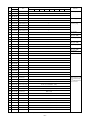
Contents
1 Read Before Servicing ................................................................
[1] Items to Be Checked ..............................................................
[2] Necessary Tools and Materials ..............................................
[3] Piping Materials ......................................................................
[4] Storage of Piping Material ......................................................
[5] Piping Machining ....................................................................
[6] Brazing....................................................................................
[7] Airtightness Test ......................................................................
[8] Vacuuming ..............................................................................
[9] Vacuum Drying........................................................................
[10] Changing Refrigerant..............................................................
[11] Remedies to be taken in case of a refrigerant leak................
[12] Characteristics of the Conventional and the New Refrigerants ..
[13] Notes on Refrigerating Machine Oil........................................
6
6
7
8
10
11
12
13
13
14
15
15
16
17
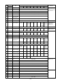
2 Restrictions ..................................................................................
[1] Electrical Work & M-NET control ............................................
[2] Types of Switch Setting and Address Setting ........................
[3] Examples of system connection ............................................
[4] Restrictions on Refrigerant Piping Length..............................
18
18
19
22
38
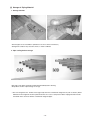
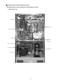
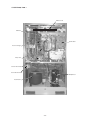
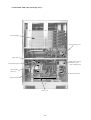
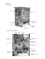
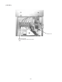
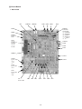
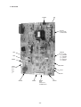
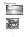
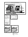
3 Components of the Heat source Unit ..........................................
[1] Appearance of the Components and Refrigerant Circuit........
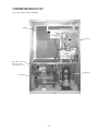
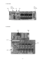
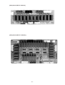
[2] Control Box ............................................................................
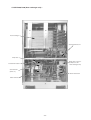
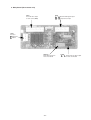
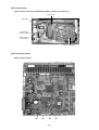
[3] Circuit Board ..........................................................................
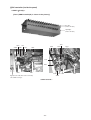
[4] BC controller (inside the panel) ..............................................
[5] BC control box ........................................................................
[6] BC controller board ................................................................
52
52
57
59
63
66
66
4 Remote Controller ........................................................................
[1] Functions and Specifications of MA and ME Remote Controllers....
[2] Group Setting and Interlocking Settings that are Made on
an ME Remote Controller......................................................
[3] Interlocking Setting via the MA Remote Controller ........................
[4] Switching to the built-in Thermo on the remote controller ......
68
68
69
73
76
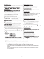
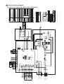
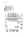
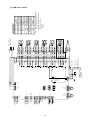
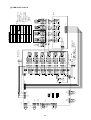
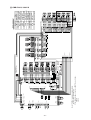
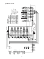
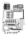
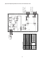
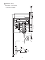
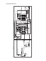
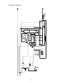
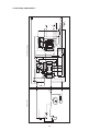
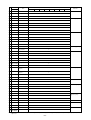
5 Electrical Wiring Diagram ............................................................
[1] PQRY-P200, P250YGM-A, PQRY-P400, P500YSGM-A ........
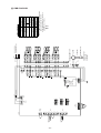
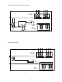
[2] CMB-P104V-G ........................................................................
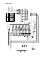
[3] CMB-P105, 106V-G ................................................................
[4] CMB-P108, 1010V-G ..............................................................
[5] CMB-P1013, 1016V-G ............................................................
[6] CMB-P104V-GB......................................................................
[7] CMB-P108V-GB......................................................................
[8] CMB-P108, 1010V-GA............................................................
[9] CMB-P1013, 1016V-GA..........................................................
[10]Power Dispatching Extension Unit for the Transmission
Lines......................................................................................
77
77
78
79
80
81
82
83
84
85
6 Refrigerant Circuit ........................................................................
[1] Refrigerant Circuit Diagram ....................................................
[2] Functions of Principal Parts....................................................
[3] BC controller ..........................................................................
87
87
93
95
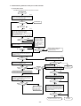
7 Control..........................................................................................
[1] Dip Switch Functions and Their Factory Settings ..................
[2] Controlling the Heat source Unit ............................................
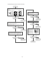
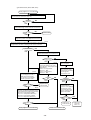
[3] Operation Flow Chart ............................................................
97
97
102
114
86
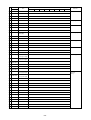
8 Test Run ......................................................................................
[1] Check Items before Test Run..................................................
[2] Test Run Method ....................................................................
[3] Operating Characteristics and Refrigerant Amount................
[4] Adjustment and Judgment of Refrigerant Amount ................
[5] Refrigerant Volume Adjustment Mode Operation ..................
[6] Symptoms that do not Signify Problems ................................
[7] Standard Operation Data (Reference Data) ..............................
120
120
120
121
121
124
128
129
9 Troubleshooting ............................................................................
[1] Check Code List ....................................................................
[2] Responding to Error Display on the Remote Controller ........
[3] Investigation of Transmission Wave Shape/Noise ..................
[4] Troubleshooting of Principal Parts ..........................................
[5] Refrigerant Leak ....................................................................
[6] BC controller service instruction ............................................
133
133
135
170
173
204
208
0 LED display .................................................................................. 211
[1] LED Monitor Display .............................................................. 211
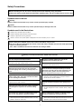
Safety Precautions
Before installing the unit, be sure to carefully read all of the following safety precautions.
These precautions provide important information regarding safety. Be sure to follow them to ensure safety.
Symbols used in the text
Warning:
Failure to follow all instructions may result in serious personal injury or death.
Caution:
Failure to follow all instructions may result in personal injury or damage to the unit.
Symbols used in the illustrations
: Indicates an action that must be avoided.
: Indicates that important instructions must be followed.
: Indicates a part which must be grounded.
: Beware of electric shock (This symbol is displayed on the main unit label.) <Color : Yellow>
After reading this handbook, hand it over to those who will be using the unit.
The user of the unit should keep this manual at hand and make it available to those who will be performing
repairs or relocating the unit.
Also, make it available to the new user when the user changes hands.
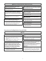
Warning : Carefully read the labels affixed to the main unit.
Have the unit professionally installed.
•
Be sure to carefully follow each step in this
handbook when installing the unit.
Improper installation by an unqualified person may
result in water leak, electric shock, or fire.
•
Place the unit on a stable, level surface that
withstands the weight of the unit to prevent the
unit from tipping over or falling causing injury as a
result.
Have all electrical work performed by a licensed
electrician according to the local regulations and
the instructions given in this manual. Secure a
circuit designated exclusively to the unit.
Only use specified cables for wiring. Securely
connect each cable, and make sure that the cables
are not straining the terminals.
•
Improper installation may result in water leak,
electric shock, smoke or fire.
• Improper installation or a lack of circuit capacity may
cause the unit to malfunction or present a risk of
electric shock, smoke, and fire.
Cables not connected securely and properly may
generate heat and cause fire.
Securely attach the terminal cover (panel) on the
unit.
Take necessary safety measures against typhoons
and earthquakes to prevent the unit from falling
over.
•
Do not make any changes or modifications to the
unit. In case of problems, consult the dealer.
Only use Refrigerant R410A as indicated on the
unit when installing or relocating the unit.
•
•
If repairs are not made properly, the unit may leak
water and present a risk of electric shock, or it may
produce smoke or cause fire.
-1-
If installed improperly, dust and/or water may enter
the unit and present a risk of electric shock, smoke,
or fire.
The use of any other refrigerant or an introduction of
air into the unit circuit may cause the unit to run an
abnormal cycle and cause the unit to burst.
Warning : Carefully read the labels affixed to the main unit.
When installing the unit in a small room, safeguard
against hypoxia that results from leaked refrigerant
reaching the threshold level.
In the event of a refrigerant gas leak, provide
adequate ventilation to the room.
•
If leaked refrigerant gas is exposed to a heat source,
noxious gases may form.
•
When relocating the air conditioner, consult the
dealer or a specialist.
With All-Fresh type air conditioners, outdoor air
may be directly blown into the room upon thermo
off. Take this into consideration when installing the
unit.
•
•
Direct exposure to outdoor air may present a health
hazard, and it may also cause food items to
deteriorate.
Improper installation may result in water leak,
electric shock, or fire.
After completing the service work, check for a
refrigerant gas leak.
•
Do not try to defeat the safety features of the
devices, and do not change the settings.
•
Consult the dealer for necessary measures to take.
Defeating the safety features on the unit such as the
pressure switch and temperature switch or using
parts other than those specified by Mitsubishi
Electric may result in fire or explosion.
If leaked gas refrigerant is exposed to a heart
source such as fan heater, stove, and electric grill,
noxious gases may form.
Only use specified parts.
•
Have the unit professionally installed.
Improper installation may cause water leak, electric
shock, smoke, or fire.
Precautions for Handling Units for Use with R410A
Caution
Do not use the existing refrigerant piping
•
•
Use a vacuum pump with a reverse-flow-check
valve.
The old refrigerant and refrigerator oil in the existing
piping contain a large amount of chlorine, which will
cause the refrigerator oil in the new unit to
deteriorate.
R410A is a high-pressure refrigerant, and the use of
the existing piping may result in bursting.
•
Do not use the following tools that have been used
with the conventional refrigerants.Prepare tools
that are for exclusive use with R410A.
(Gauge manifold, charging hose, gas leak detector,
reverse-flow check valve, refrigerant charge base,
vacuum gauge, and refrigerant recovery
equipment.)
Use refrigerant pipes made of C1220 phosphorus
deoxidized copper categorized under H3000
(Copper and Copper Alloy Seamless Pipes and
Tubes), a standard set by JIS. Keep the inner and
outer surfaces of the pipes clean and free of
contaminants such as sulfur, oxides, dust/dirt,
shaving particles, oils, and moisture.
•
If other types of valves are used, the vacuum pump
oil will flow back into the refrigerant cycle and cause
the refrigerator oil to deteriorate.
•
Contaminants inside the refrigerant piping will cause
the refrigerant oil to deteriorate.
•
-2-
If refrigerant and /or refrigerant oil left on these tools
are mixed in with R410A, or if water is mixed with
R410A, it will cause the refrigerant to deteriorate.
Since R410A does not contain chlorine, gas-leak
detectors for conventional refrigerators will not work.
Caution
Do not use a charging cylinder.
Store the piping to be used during installation
indoors, and keep both ends of the piping sealed
until immediately before brazing. (Keep elbows and
other joints wrapped in plastic.)
•
•
If dust, dirt, or water enters the refrigerant cycle, it
may cause the oil in the unit to deteriorate or may
cause the compressor to malfunction.
Exercise special care when handling the tools.
•
Use a small amount of ester oil, ether oil, or
alkylbenzene to coat flares and flange connections.
•
A large amount of mineral oil will cause the
refrigerating machine oil to deteriorate.
An introduction of foreign objects such as dust, dirt,
or water into the refrigerant cycle will cause the
refrigerating machine oil to deteriorate.
Only use R410A refrigerant.
•
Use liquid refrigerant to charge the system.
•
The use of charging cylinder will change the
composition of the refrigerant and lead to power
loss.
The use of refrigerants containing chlorine (i.e. R22)
will cause the refrigerant to deteriorate.
Charging the unit with gas refrigerant will cause the
refrigerant in the cylinder to change its composition
and will lead to a drop in performance.
Before Installing the Unit
Warning
Do not install the unit in a place where there is a
possibility of flammable gas leak.
When installing the unit in a hospital, take
necessary measures against noise.
•
•
Leaked gas accumulated around the unit may start a
fire.
High-frequency medical equipment may interfere
with the normal operation of the air conditioning unit
or the air conditioning unit may interfere with the
normal operation of the medical equipment.
Do not use the unit to preserve food, animals,
plants, artifacts, or for other special purposes.
•
Do not place the unit on or over things that may
not get wet.
The unit is not designed to provide adequate
conditions to preserve the quality of these items.
•
Do not use the unit in an unusual environment.
•
•
•
The use of the unit in the presence of a large
amount of oil, steam, acid, alkaline solvents, or
special types of sprays may lead to a remarkable
drop in performance and/or malfunction and
presents a risk of electric shock, smoke, or fire.
The presence of organic solvents, corroded gas
(such as ammonia, sulfur compounds, and acid)
may cause gas or water leak.
-3-
When humidity level exceeds 80% or when the
drainage system is clogged, indoor units may drip
water.
Installation of a centralized drainage system for the
outdoor unit may also need to be considered to
prevent water drips from the outdoor units.
Before Installing (Relocating) the Unit or Performing Electric Work
Warning
When installing or relocating the unit, make sure
that no substance other than the specified
refrigerant(R410A) enters the refrigerant circuit.
•
Any presence of foreign substance such as air can
cause abnormal pressure rise or explosion.
Caution
Use breakers and fuses (electrical current breaker,
remote switch <switch + Type-B fuse>, molded
case circuit breaker) with a proper current
capacity.
Ground the unit.
•
Do not connect the grounding on the unit to gas
pipes, water pipes, lightning rods, or the grounding
terminals of telephones. Improper grounding
presents a risk of electric shock, smoke, fire, or the
noise caused by improper grounding may cause the
unit to malfunction.
•
Make sure the wires are not subject to tension.
•
The use of large-capacity fuses, steel wire, or
copper wire may damage the unit or cause smoke or
fire.
Do not spray water on the air conditioners or
immerse the air conditioners in water.
If the wires are too taut, they may break or generate
heat and/or smoke and cause fire.
•
Water on the unit presents a risk of electric shock.
Install a breaker for current leakage at the power
source to avoid the risk of electric shock.
Periodically check the platform on which the unit is
placed for damage to prevent the unit from falling.
•
•
Without a breaker for current leakage, there is a risk
of electric shock, smoke, or fire.
When installing draining pipes, follow the
instructions in the manual, and make sure that they
properly drain water so as to avoid dew
condensation.
Use wires that are specified in the installation
manual.
•
If the unit is left on a damaged platform, it may
topple over, causing injury.
The use of other types of wires presents a risk of
electrical current leak, electric shock, smoke, or fire.
•
If not installed properly, they may cause water leaks
and damage the furnishings.
Exercise caution when transporting products.
•
•
•
•
Do not try to move equipments over 20kg (approx.
44 lbs.) alone.
Do not use the PP bands used on some packages
for transportation.
Wear protective gloves to avoid injury caused by
touching the fins on the heat exchanger with bare
hands.
When using a suspension bolt to transport the heatsource unit, use a four-point suspension. A threepoint suspension does not provide adequate stability
and presents a risk of accidents.
Properly dispose of the packing materials.
• Things such as nails and wood pieces may be
included in the package. Dispose of them properly to
prevent injury.
• Plastic bags present a choking hazard to children.
Tear up the plastic bags before disposing of them to
prevent accidents.
-4-
Before the Test Run
Caution
Turn on the unit at least 12 hours before the test
run.
Do not turn off the power immediately after
stopping the unit.
•
•
Keep the unit on throughout the season.
Turning the unit off during the season may cause
problems.
Do not operate the unit without air filters.
Do not operate switches with wet hands to avoid
electric shock.
•
Do not touch the refrigerant pipes with bare hands
during and immediately after operation.
•
Depending on the state of the refrigerant in the
system, certain parts of the unit such as the pipes
and compressor may become very cold or hot and
may subject the person to frost bites or burning.
Do not operate the unit without panels and safety
guards in their proper places.
•
Allow for at least five minutes before turning off the
unit; otherwise, the unit may leak water or
experience other problems.
They are there to keep the users from injury from
accidentally touching rotating, high-temperature, or
high-voltage parts.
-5-
Dust particles in the air may clog the system and
cause malfunction.
¡ Read Before Servicing
[1] Items to Be Checked
1. Verify the type of refrigerant used by the unit to be serviced.
Refrigerant Type : R410A
2. Check the symptom exhibited by the unit to be serviced.
Look in this service handbook for symptoms relating to the refrigerant cycle.
3. Be sure to carefully read the Safety Precautions at the beginning of this document.
4. Prepare necessary tools: Prepare tools exclusive for use with each refrigerant type.
Refer to P7 for more information.
5. Verification of the connecting pipes: Verify the type of refrigerant used for the unit to be
moved or replaced.
• Use pipes made of phosphorus deoxidized copper. Keep the inner and outer surfaces of the pipes clean and
free of contaminants such as sulfur, oxides, dust/dirt, shaving particles, oils, and moisture.
• Contaminants inside the refrigerant piping will cause the refrigerant oil to deteriorate.
6. If there is a gas leak or if the remaining refrigerant is exposed to an open flame, a noxious gas
hydrofluoric acid may form. Keep workplace well ventilated.
CAUTION
1. Install new pipes immediately after removing old ones to keep moisture out of the refrigerant circuit.
2. Chloride in some types of refrigerants such as R22 will cause the refrigerating machine oil to
deteriorate.
-6-
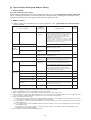
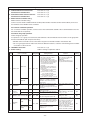
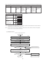
[2] Necessary Tools and Materials
Prepare the following tools and materials necessary for installing and servicing the unit.
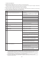
[Necessary tools for use with R410A (Adaptability of tools that are for use with R22 and R407C)]
1. To be used exclusively with R410A (not to be used if used with R22 or R407C)
Tools/Materials
Use
Notes
Gauge Manifold
Charging Hose
Refrigerant Recovery Equipment
Refrigerant Cylinder
Evacuating, refrigerant charging
Evacuating, refrigerant charging
Refrigerant recovery
Refrigerant charging
Refrigerant Cylinder Charging Port
Flare Nut
Refrigerant charging
Connecting the unit to piping
5.09MPa on the High-pressure side.
Hose diameter larger than the conventional ones.
Write down the refrigerant type.
Pink in color at the top of the cylinder.
Hose diameter larger than the conventional ones.
Use Type-2 Flare nuts.
(That are in compliance with JIS B 8607).
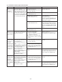
2. Tools and materials that may be used with R410A with some restrictions
Tools/Materials
Use
Notes
Gas leak detector
Vacuum Pump
Detection of gas leaks
Vacuum drying
Flare Tool
Flare machining of piping
Refrigerant Recovery Equipment
Recovery of refrigerant
The ones for HFC type refrigerant may be used.
May be used if a reverse flow check adaptor is
attached.
Changes have been made in the flare machining
dimension. Refer to the next page.
May be used if designed for use with R410A.
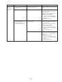
3. Tools and materials that are used with R22 or R407C that can also be used with R410A
Tools/Materials
Use
Notes
Vacuum Pump with a Check valve Vacuum drying
Bending pipes
Bender
Tightening flare nuts
Torque Wrench
Pipe Cutter
Welder and Nitrogen Cylinder
Refrigerant Charging Meter
Vacuum Gauze
Only ø 12.70 (1/2”) and ø 15.88 (5/8”) have a
larger flare machining dimension.
Cutting pipes
Welding pipes
Refrigerant charging
Checking vacuum degree
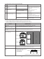
4. Tools and materials that must not be used with R410A
Tools/Materials
Charging Cylinder
Use
Notes
Refrigerant Charging
Must not be used with R410A-type units.
Tools for R410A must be handled with special care; keep moisture and dust from entering the
cycle.
-7-
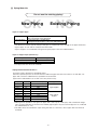
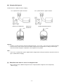
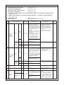
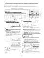
[3] Piping Materials
Do not use the existing piping!
OK
NO
New Piping
Existing Piping
<Types of copper pipe>
Type-O pipes
Type-1/2H pipes
Soft copper pipes (annealed copper pipes)
They can be bent easily with hands.
Hard copper pipes (straight pipes)
Stronger than type-O pipes of the same radial thickness.
• The distinction between type-O and type-1/2H pipes is made based on the strength of the pipes themselves.
• Type-O pipes are soft and can easily be bent with hands.
• Type-1/2H pipes are considerably stronger than type-O pipes of the same radial thickness.
<Types of Copper Pipes (Reference)>
Maximum Operation Pressure
3.45 MPa
4.30 MPa
Applicable Refrigerants
R22, R407C etc.
R410A
✻ Use pipes that meet the local standards.
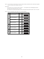
<Piping Materials/Radial Thickness>
Use pipes made of phosphorus deoxidized copper.
Since the operation pressure of the units that use R401A is higher than that of the units for use with R22, use
pipes with at least the radial thickness specified in the chart below.
(Pipes with a radial thickness of 0.7 mm or less may not be used.)
Size(mm)
ø 6.35
ø 9.52
ø 12.7
ø 15.88
ø 19.05
ø 22.2
ø 25.4
ø 28.58
ø 31.75
Size(inch)
1/4”
3/8”
1/2”
5/8”
3/4”
7/8”
1”
1 1/8”
1 1/4”
Radial Thickness(mm)
0.8t
0.8t
0.8t
1.0t
1.0t
1.0t
1.0t
1.0t
1.1t
Type
Type-O pipes
Type-1/2H or
H pipes
✻ Although it was possible to use type-O for pipes with a size of up to ø19.05 (3/4”) with conventional refrigerants, use type-1/2H pipes for units that use R410A. (Type-O pipes may be used if the pipe size is ø19.05 and
the radial thickness is 1.2t.)
✻ The table shows the standards in Japan. Using this table as a reference, choose pipes that meet the local
standards.
-8-
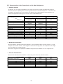
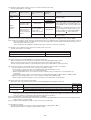
<Indication of the radial thickness and refrigerant type on the piping materials>
“Radial thickness” and “Refrigerant Types” are indicated on the insulation material on the piping materials for the
new refrigerant.
Indication of the radial thickness (mm)
Radial thickness
0.8
1.0
Symbols
08
10
Indication of the refrigerant type
Refrigerant type
Type1 R22, R407C
Type2 R410A
Symbol
1
2
<Example of the symbols indicated on the insulation material>
~08-2~
Appears every 1 m
The type of piping materials can also be found on the package.
<Example of a label found on the package>
2
: common to type 1 and type 2
Refrigerant Type
: R22,R407C,R410A
Bore diameter and radial thickness of the copper piping : 9.52✕0.8, 15.88✕1.0
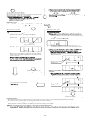
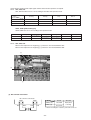
<Flare Machining (type-O and OL only)>
The flare machining dimensions for units that use R410A is larger than those for units that use R22 in order to
increase air tightness.
Flare Machining Dimension(mm)
Dimension A
External dimension
of pipes
ø 6.35
ø 9.52
ø 12.7
ø 15.88
ø 19.05
Size
1/4”
3/8”
1/2”
5/8”
3/4”
Dimension A
R410A
9.1
13.2
16.6
19.7
24.0
R22
9.0
13.0
16.2
19.4
23.3
If a clutch type flare tool is used to machine flares on units that use R410A, make the protruding part of the
pipe between 1.0 and 1.5mm. Copper pipe gauge for adjusting the length of pipe protrusion is useful.
<Flare Nut>
Type-2 flare nuts instead of type-1 s are used to increase the strength. The size of some of the flare nuts have
also been changed.
Flare nut dimension(mm)
Dimension B
External dimension
of pipes
ø 6.35
ø 9.52
ø 12.7
ø 15.88
ø 19.05
Size
1/4”
3/8”
1/2”
5/8”
3/4”
Dimension B
R410A(Type2)
R22(Type1)
17.0
17.0
22.0
22.0
26.0
24.0
29.0
27.0
36.0
36.0
✻ The table shows the standards in Japan. Using this table as a reference, choose pipes that meet the local
standards.
-9-
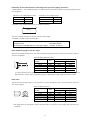
[4] Storage of Piping Material
1. Storage location
OK
NO
Store the pipes to be used indoors. (Warehouse at site or owner’s warehouse)
Storing them outdoors may cause dirt, waste, or water to infiltrate.
2. Pipe sealing before storage
OK
NO
Both ends of the pipes should be sealed until immediately before brazing.
Wrap elbows and T’s in plastic bags for storage.
✻ The new refrigerator oil is 10 times more hygroscopic than the conventional refrigerator oil (such as Suniso). Water
infiltration in the refrigerant circuit may deteriorate the oil or cause a compressor failure. Piping materials must be
stored with more care than with the conventional refrigerant pipes.
- 10 -
[5] Piping Machining
Use ester oil, ether oil or alkylbenzene (small amount) as the refrigerator oil to coat flares and flange connections.
Reason :
1. The refrigerator oil used for the equipment is highly hygroscopic and may introduce water inside.
Notes :
• Introducing a great quantity of mineral oil into the refrigerant circuit may also cause a compressor failure.
• Do not use oils other than ester oil, ether oil or alkylbenzene.
- 11 -
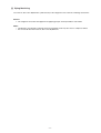
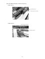
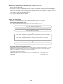
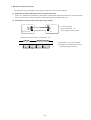
[6] Brazing
No changes from the conventional method, but special care is required so that foreign matter (ie. oxide scale, water, dirt,
etc.) does not enter the refrigerant circuit.
Example : Inner state of brazed section
When non-oxide brazing was not used
When non-oxide brazing was used
Items to be strictly observed :
1. Do not conduct refrigerant piping work outdoors on a rainy day.
2. Apply non-oxide brazing.
3. Use a brazing material (BCuP-3) which requires no flux when brazing between copper pipes or between a copper pipe
and copper coupling.
4. If installed refrigerant pipes are not immediately connected to the equipment, then braze and seal both ends of them.
Reasons :
1. The new refrigerant oil is 10 times more hygroscopic than the conventional oil. The probability of a machine failure if
water infiltrates is higher than with conventional refrigerant oil.
2. A flux generally contains chlorine. A residual flux in the refrigerant circuit may generate sludge.
Note :
• Commercially available antioxidants may have adverse effects on the equipment due to its residue, etc. When
applying non-oxide brazing, use nitrogen.
- 12 -
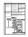
[7] Airtightness Test
No changes from the conventional method. Note that a refrigerant leakage detector for R22 or R407C cannot detect
R410A leakage.
NO
NO
Halide torch
R22 or R407C leakage detector
Items to be strictly observed :
1. Pressurize the equipment with nitrogen up to the design pressure and then judge the equipment’s airtightness, taking
temperature variations into account.
2. When investigating leakage locations using a refrigerant, be sure to use R410A.
3. Ensure that R410A is in a liquid state when charging.
Reasons :
1. Use of oxygen as the pressurized gas may cause an explosion.
2. Charging with R410A gas will lead the composition of the remaining refrigerant in the cylinder to change and this
refrigerant can then not be used.
Note :
• A leakage detector for R410A is sold commercially and it should be purchased.
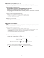
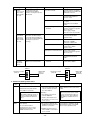
[8] Vacuuming
1. Vacuum pump with check valve
A vacuum pump with a check valve is required to prevent the vacuum pump oil from flowing back into the refrigerant
circuit when the vacuum pump power is turned off (power failure).
It is also possible to attach a check valve to the actual vacuum pump afterwards.
2. Standard degree of vacuum for the vacuum pump
Use a pump which reaches 65Pa or below after 5 minutes of operation.
In addition, be sure to use a vacuum pump that has been properly maintained and oiled using the specified oil. If the
vacuum pump is not properly maintained, the degree of vacuum may be too low.
3. Required accuracy of the vacuum gauge
Use a vacuum gauge that can measure up to 650Pa. Do not use a general gauge manifold since it cannot measure a
vacuum of 650Pa.
4. Evacuating time
• Evacuate the equipment for 1 hour after 650Pa has been reached.
• After envacuating, leave the equipment for 1 hour and make sure the that vacuum is not lost.
5. Operating procedure when the vacuum pump is stopped
In order to prevent a backflow of the vacuum pump oil, open the relief valve on the vacuum pump side or loosen the
charge hose to drawn in air before stopping operation.
The same operating procedure should be used when using a vacuum pump with a check valve.
- 13 -
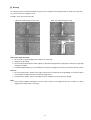
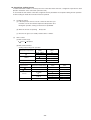
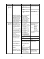
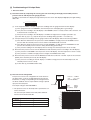
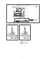
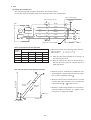
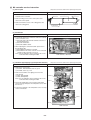
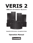
[9]
Vacuum Drying
Photo 1 15010H
Photo 2 14010
Recommended vacuum gauge : ROBINAIR 14010 Thermistor Vacuum Gauge
1. Vacuum pump with reverse-flow check valve (Photo 1)
To prevent vacuum pump oil from flowing back into the refrigerant circuit upon turning off the vacuum pump’s power
source, use a vacuum pump equipped with a reverse flow check valve.
A check valve may also be added to the vacuum pump currently in use.
2. Standard of vacuum degree (Photos 1 and 2)
Use a vacuum pump that shows a vacuum degree of 65Pa or less after 5 minutes of operation. Use a pump wellmaintained with an appropriate lubricant.
3. Required precision of vacuum gauge
Use a vacuum gauge that registers a vacuum degree of 650Pa and measures at intervals of 130Pa. (A recommended
vacuum gauge is shown in Photo 2.)
Do not use a vacuum gauge that does not register a vacuum degree of 650Pa.
4. Evacuation time
• After the vacuum gauge has registered the vacuum degree of 650Pa, evacuate for 1 hour. (A thorough vacuum drying
removes moisture in the pipes.)
• Verify that the vacuum degree has not risen by more than 130Pa 1 hour after evacuation. A rise by less than 130Pa is
acceptable.
• If it has exceeded by more than 130Pa, conduct vacuuming following the instructions in the “6. Special vacuum drying”
section.
5. Procedures for stopping vacuum pump
To prevent the reverse flow of vacuum pump oil, open the relief valve on the vacuum pump side, or draw in air by
loosening the charge hose, and then stop the operation.
The same procedures should be followed when stopping a vacuum pump with a reverse-flow check valve.
6. Special vacuum drying
• When 650Pa or lower degree of vacuum cannot be attained after 3 hours of evacuation, it is likely that water has
penetrated the system or that there is a leak. When water infiltration is suspected, vacuum with nitrogen gas.
After breaking the vacuum, pressurize the system with nitrogen gas to a degree of 0.05MPa, and conduct an evacuation
again. Repeat it until 650Pa or lower degree of vacuum is attained or the vacuum pressure rise will be lost.
• Only use nitrogen gas for vacuum breaking. (Use of oxygen may cause an explosion.)
- 14 -
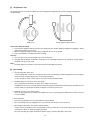
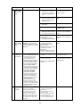
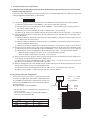
[10] Changing Refrigerant
R410A must be in a liquid state when charging.
For a cylinder with a syphon attached
For a cylinder without a syphon attached
Cylinder
Cylinder
Cylinder color identification
R407C-Gray
R410A-Pink
Charged with liquid refrigerant
Valve
Valve
Liquid
Liquid
Reasons :
1. R410A is a pseudo-azeotropic refrigerant (boiling point R32 = -52˚C, R125 = -49˚C) and can roughly be handled
in the same way as R22; however, be sure to fill the refrigerant from the liquid side, for doing so from the gas
side will somewhat change the composition of the refrigerant in the cylinder.
Note :
• In the case of a cylinder with a syphon, liquid R410A is charged without turning the cylinder up side down. Check the
type of cylinder before charging.
[11] Remedies to be taken in case of a refrigerant leak
When refrigerant leaks, additional refrigerant may be charged. (Add the refrigerant from the liquid side.)
✻Refer to 9-[5].
- 15 -
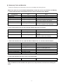
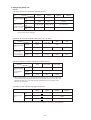
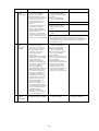
[12] Characteristics of the Conventional and the New Refrigerants
1. Chemical property
As with R22, the new refrigerant (R410A) is low in toxicity and a chemically stable non-flammable refrigerant.
However, because the specific gravity of steam is greater than that of air, leaked refrigerant in a closed room will
accumulate at the bottom of the room and may cause hypoxia. Also, leaked refrigerant exposed directly to an
open flame will generate noxious gasses. Use the unit in a well-ventilated room.
New Refrigerant
(HFC system)
Composition (wt%)
Type of refrigerant
Chloride
Safety Class
Molecular Weight
Boiling Point
Steam Pressure (25˚C,MPa)(gauge)
Saturated Steam Density (25˚C,kg/m3)
Flammability
Ozone Depletion Coefficient (ODP)✻1
Global Warming Coefficient (GWP)✻2
Refrigerant charging method
Addition of refrigerant in case of a leak
R410A
R32/R125
(50/50)
Simulated azeotropic
refrigerant
Not contained
A1/A1
72.6
-51.4
1.557
64.0
Non-flammable
0
1730
Liquid charging
Possible
R407C
R32/R125/R134a
(23/25/52)
Non-azeotropic
refrigerant
Not contained
A1/A1
86.2
-43.6
0.9177
42.5
Non-flammable
0
1530
Liquid charging
Possible
✻1: When CFC11 is used as a reference
Conventional Refrigerant
(HCFC system)
R22
R22
(100)
Single refrigerant
Contained
A1
86.5
-40.8
0.94
44.4
Non-flammable
0.055
1700
Gas charging
Possible
✻2: When CO2 is used as a reference
2. Refrigerant Composition
Because R410A is a simulated azeotropic refrigerant, it can be handled in almost the same manner as a single
refrigerant such as R22. However, if the refrigerant is removed in the vapor phase, the composition of the refriger
ant in the cylinder will somewhat change.
Remove the refrigerant in the liquid phase. Additional refrigerant may be added in case of a refrigerant leak.
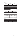
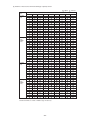
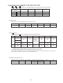
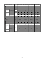
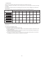
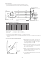
3. Pressure Characteristics
The pressure in the units that use R410A is 1.6 times as great as that in the units that use R22.
Pressure (gauge)
Temperature (˚C)
-20
0
20
40
60
65
R410A
MPa
0.30
0.70
1.34
2.31
3.73
4.17
- 16 -
R407C
MPa
0.18
0.47
0.94
1.44
2.44
2.75
R22
MPa
0.14
0.40
0.81
1.44
2.33
2.60
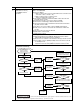
[13] Notes on Refrigerating Machine Oil
1. Refrigerating Machine Oil in the HFC Refrigerant System
HFC type refrigerants use a refrigerating machine oil different from that used in the R22 refrigerant system.
Please note that the ester oil sealed in the unit is not the same as commercially available ester oil.
Refrigerant
R22
R407C
R410A
Refrigerating machine oil
Mineral oil
Ester oil
Ester oil
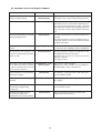
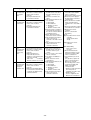
2. Effects of the ✻Contaminants in the System
Refrigerating machine oil used in the HFC system must be handled more carefully than conventional mineral oils.
The table below shows the effects of air, moisture, and contaminants in the refrigerating machine oil on the refrigeration cycle.
<The Effects of Air, Moisture, and Contaminants in the Refrigerating Machine Oil on the Refrigeration Cycle.>
Cause
Symptom
Expansion valve and capillary freeze
Water infiltration
Hydrolysis
Oxidization
Air infiltration
Dust, dirt
Infiltration
of
contaminants
Sludge formation
Generation of acid
Oxidization
Oil degradation
Adhesion to expansion valve and capillary
Infiltration of contaminants into the compressor
Mineral oil Sludge formation and adhesion
etc.
Oil degradation
Effects on the refrigeration cycle
Clogged expansion valve and capillary
Poor cooling performance
Compressor overheat
Poor motor insulation
Motor burning
Coppering of the orbiting part
Locking
Burning in the orbiting part
Expansion valve/capillary
Poor cooling performance
Drier clogging
Compressor overheat
Burning in the orbiting part
Expansion valve and capillary clogging
Poor cooling performance
Compressor overheat
Burning in the orbiting part
✻ “ Contaminants ” is defined as moisture, air, process oil, dust/dirt, the wrong types of refrigerant and refrigerating machine oil.
- 17 -
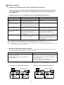
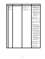
™ Restrictions
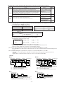
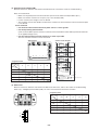
[1] Electrical Work & M-NET control
1. Attention
➀ Follow ordinance of your governmental organization for technical standard related to electrical equipment, wiring
regulations, and guidance of each electric power company.
➁ Wiring for control (hereinafter referred to as transmission line) shall be (5cm or more) apart from power source wiring so
that it is not influenced by electric noise from power source wiring. (Do not insert transmission line and power source wire
in the same conduit.)
➂ Be sure to provide designated grounding work to heat source unit.
➃ Give some allowance to wiring for electrical part box of indoor and heat source unit, because the box is sometimes removed at the time of service work.
➄ Never connect 380~415V(220~240V) power source to terminal block of transmission line.If connected,electrical parts
will be burnt out
➅ Use 2-core shield cable for transmission line. If transmission lines of different systems are wired with the same multiplecore cable, the resultant poor transmitting and receiving will cause erroneous operations.
Heat
source
unit
Indoor unit
OK
Heat
source
unit
Indoor unit
NO
2-core cable
Multiplecore cable
Remote
controller
BC controller
Remote
controller
BC controller
2-core cable
✻ The BC controller is connected to WR2 and R2 systems.
2. Types of control cable
Transmission cables
M-NET Remote controller cables
Type of cable
Shielding wire (2-core)
CVVS,CPEVS or MVVS
Cable diameter
More than 1.25mm2
0.3 ~ 1.25mm2
(0.75 ~ 1.25mm2) ✻1
—
When 10m is exceeded, use cables with
the same specification as transmission cables.
Remarks
MA Remote controller cables
Sheathed 2-core cable (unshielded)
CVV
✻1 Connected with simple remote controller.
CVVS,MVVS : PVC insulated PVC jacketed shielded control cable
CPEVS
: PE insulated PVC jacketed shielded communication cable
CVV
: PV insulated PVC sheathed control cable
- 18 -
0.3 ~ 1.25mm2
(0.75 ~ 1.25mm2) ✻1
Max length : 200m
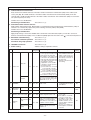
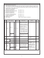
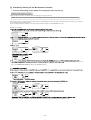
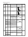
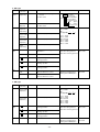
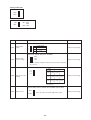
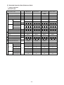
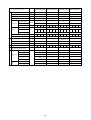
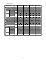
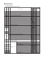
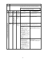
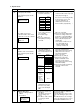
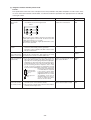
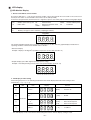
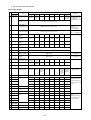
[2] Types of Switch Setting and Address Setting
1. Switch setting
Type and method of switch setting
Switch setting vary depending on the system configuration. Make sure to read “[3] Examples of system connection”
before conducting electrical work. Turn off the power before setting the switch. Operating the switch while the unit is
being powered will not change the setting, and the unit will not properly function.
2. Address setting
(1) Address setting varies depending on the system configuration. See “[3] Examples of system connection”
section for details.
Unit or controller
Indoor unit
Main/sub units
Address
setting range
0, 01~50
(Note 1)
Lossnay
M-NET
remote
controller
Assign any unused address after setting all indoor units.
00
Set to the lowest address of the indoor main unit
within the same group + 100.
Sub remote controller
151~200
(Note 2)
Set to the lowest address of the indoor main unit
within the same group + 150.
BC controller (Main)
No address setting required. (When operating with 2 remote controllers,
the main/sub selector switch must be set.
0, 51~100
(Note 1, 3, 4)
Use the address that equals the sum of the smallest indoor
unit address in the same refrigerant system and 50.
52~100
(Note 3, 4)
Use the address that equals the sum of the address of the
heat source unit in the same refrigerant system and 1.
101
Main
00
Use the address that equals the sum of the smallest
address of the indoor unit out of all the indoor units
that are connected to the BC controller and 50.
When a sub BC controller is connected, the automatic
start up function will not be available.
BC controller (Sub)
System
controller
00
101~150
Outdoor (Heat source) unit
Factory
setting
Assign the smallest address to the indoor unit to
become the main unit within the same group, and
then use sequential numbers to assign an address
to all the indoor units in the group. (Note 5)
If applicable, set the sub BC controllers in an R2
system in the following order:
(1) Indoor unit to be connected to the main BC controller
(2) Indoor unit to be connected to No.1 sub BC controller
(3) Indoor unit to be connected to No.2 sub BC controller
Set the address so that (1) < (2) < (3)
Main remote controller
MA remote controller
Auxiliary
units
Setting method
Group remote controller
201~250
Set to the lowest No. of the group to be controlled + “200.”
201
System remote controller
201~250
Choose any number within the range of addresses shown left.
201
ON/OFF remote controller
201~250
Set to the lowest No. of the group desired to be controlled + “200.”
201
Schedule timer (for M-NET)
201~250
Choose any number within the range of addresses shown left.
202
0, 201~250
Choose any number within the range of addresses shown left.
However when using with the upper SC setting, or wishing to
control the k-control units, set to “0.”
000
201~250
Choose any number within the range of ad-dresses shown left.
247
Centralized controller
(Note 5)
LM adapter
Notes:
1. Address setting is not required for a single refrigerant system (with a few exception).
2. When setting M-NET remote controller address to “200,” make it “00.”
3. When setting the heat source unit and outdoor auxiliary unit address to “100,” make it “50.”
4. When an address in a system overlapped with the heat source unit or BC controller (Main) address of other refrigerant system,
choose an another address within the set range that is not in use (with a few exceptions).
5. When controlling the K-control units;
(1) A K-transmission converter (Model name: PAC-SC25KA) is required. To set the address for the K-transmission converter,
set it to the lowest address of the K-control unit to be controlled + 200.
(2) Set the address of the system controller (G-50A) to “0.” The K-control unit can only be controlled by the system controller
with the address “0.”
(3) To control both K-control unit and M-NET model unit, make the address of the K-control unit larger than that of the indoor
unit of M-NET model.
Group-register on the system controller so that the group No. and the lowest address of the K-controlled indoor units
belonging to the group will be identical.
6. BC controller is found only in the R2 and WR2 systems.
- 19 -
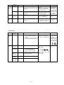
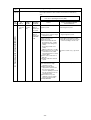
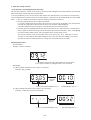
(2) Setting the power supply selecting connector for outdoor unit (Heat source unit)
(Factory setting: CN41 is connected.)
System
configuration
Connection with the
system controller
Power supply
unit for transmission
lines
_
_
_
n/a
_
n/a
applicable
Single-refrigerant
system
Multiplerefrigerant
system
With connection to
the indoor-outdoor
transmission line
With connection to
the transmission
line for centralized
control
Grouping
operation of
different
Unnecessary
applicable//n/a
Unnecessary (Note 2)
Power supplied
from outdoor
(Heat source) unit
applicable//n/a
applicable
applicable//n/a
(
)
The setting of the power supply selecting
connector
Use CN41 as is.
(Factory setting)
Disconnect the male connector from the female
power supply switch connector (CN41) and connect it to the female power supply switch connector (CN40) on only one of the outdoor units.
(Note 3)
Connect the S (shielded) terminal on the terminal block (TB7) on the outdoor (Heat source)
unit whose CN41 was replaced with CN40 to
the earth terminal ( ) on the electric box.
Use CN41 as is.
(Factory setting)
(Note 1) The total number of connectible units in the refrigerant system will be limited. Refer to DATA BOOK.
(Note 2) The need for a power supply unit for transmission lines depends on the system configuration. Refer to DATA BOOK.
(Note 3) When connecting a system controller to the transmission line for centralized control or performing a group operation of units in
different refrigerant systems, the replacement of male power supply switch connector (CN41) must be performed only on one
of the heat source units in the system.
(If a model between 34 and 50 HP is included in the system, replace the connector on that unit.)
(3) Settings for the centralized control switch on the outdoor (heat source) unit
(Factory setting: SW2-1 set to “OFF”)
System configuration
Connection with the system controller : n/a
Connection with the system controller : applicable (Note 1)
Switch setting for centralized control (SW2-1)
Leave it to OFF.(Factory setting)
ON
(Note 1) When only the LM adapter is connected, leave SW2-1 to OFF (as it is).
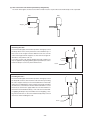
(4) Indoor unit port switch setting (R2/WR2 series (Factory Setting: “0”))
Make the settings for the port switch that corresponds to the connected BC (Main/Sub) controller.
When more than two ports are used, make the setting on the port with a smaller port number.
The total capacity and the number of connectable indoor units per port is 90 and below, and 3 respectively.
(5) Selecting the position of temperature detection for the indoor unit (Factory setting: SW1-1 set to “OFF”.)
1To use the built-in sensor on the remote controller, set the SW1-1 to ON.
✻Some models of remote controllers are not equipped with a built-in temperature sensor.
Use the built-in temperature sensor on the indoor unit instead.
✻When using the built-in sensor on the remote controller, install the remote controller where room temperature can
be detected.
(Note) Factory setting for SW1-1 on the indoor unit of the All-Fresh Models (PEFY-P, M-E-F, PFFY-P, RM-E-F) is ON.
2When an optional temperature sensor is used, set SW1-1 to OFF, and set SW3-8 to ON.
✻When using an optional temperature sensor, install it where room temperature can be detected.
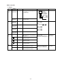
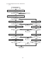
(6) Various start-stop controls (Indoor unit settings)
Each indoor unit (or group of indoor units) can be controlled individually by setting SW 1-9 and 1-10.
Function
Operation of the indoor unit when the operation is resumed after the unit was stopped
Power ON/OFF by the plug (Note 1, 2, 3) Indoor unit will go into operation regardless of its operation status before power off (power failure). (In approx. 5 minutes)
Indoor unit will go into operation if it was in operation when the power was turned off (or cut off due to power failure). (In approx. 5 minutes)
Automatic restoration
after power failure
Indoor unit will remain stopped regardless of its operation status before power off (power failure).
Setting (SW1) (Note 4)
9
10
OFF
ON
ON
OFF
OFF
OFF
(Note 1) Do not cut off power to the outdoor (Heat source) unit.
Cutting off the power supply to the outdoor (Heat source) unit will cut off the power supply to the crankcase heater and may
cause the compressor to malfunction when the unit is put back into operation.
(Note 2) Not applicable to units with a built-in drain pump or humidifier
(Note 3) Models with a built-in drain pump cannot be turned on/off by the plug individually. All the units in the same refrigerant circuits
will be turned on or off by the plug.
(Note 4) Requires that the dipswitch settings for all the units in the group be made.
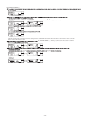
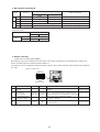
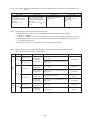
(7) Miscellaneous settings
Cooling-only setting for the indoor unit: Cooling only model (Factory setting: SW3-1 “OFF.”)
When using indoor unit as a cooling-only unit, set SW3-1 to ON.
- 20 -
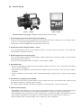
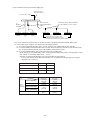
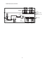
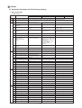
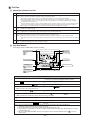
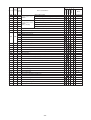
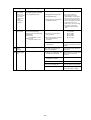
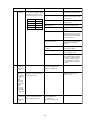
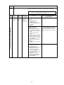
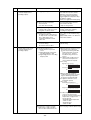
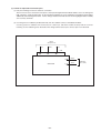
(8) Various types of control using input-output signal connector on the heat source unit (Connection options)
Signal
type
Usage
Function
Prohibiting cooling/heating operation (thermo OFF) by an external input to the heat
source unit.
✻Can be used as a demand control function for each refrigerant system.
Performs a low-noise-level operation of the outdoor unit by an external input to the
heat source unit. (The unit can perform a night mode operation under the following
conditions: Outdoor air temperature below 30˚C during cooling operation/Outdoor
air temperature above 3˚C during heating operation.
Forces the heat source unit to stop by receiving a contact signal from the pump
interlock circuit.
Input
Compressor ON/OFF (level)
CN3D
Night mode or
step demand (level) (Note 1)
Pump interlock
signal input (level)
TB8
Operation status of
the compressor
How to extract signals from the heat source unit.
✻Can be used as an operation status display device.
✻Can be used for an interlock operation with external devices.
Output
Terminal
CN51
Error status or freeze
prevention output (Note 2)
Operation-ON signal
(Note 3)
TB8
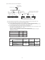
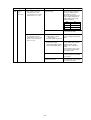
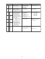
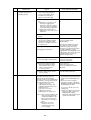
(Note 1) The night mode function is enabled when Dip SW 4-7 is set to OFF.
When Dip SW4-7 are set to ON, step demand control is possible, using different configurations of night mode
input and Compressor ON/OFF input settings.
SW4-7:OFF (Compressor ON/OFF, Night mode)
Compressor ON/OFF
CN3D 1-3P
Night mode
CN3D 1-2P
Open
ON
Open
OFF
Short
OFF
Short
ON
SW4-7:ON (Step demand)
CN3D 1-2P
Open
Short
Open
100% (No demand)
75%
Short
0%
50%
CN3D 1-3P
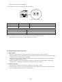
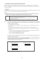
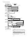
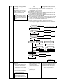
Note the following steps to be taken when using the STEP DEMAND
(Example) When witching from 100% to 50%
Demand control
steps
(Wrong) 100%
→
(Correct) 100%
→
0% →
NO
75% →
OK
50%
50%
If the step listed as the wrong example above is taken, thermo may go off.
The percentage of the demand listed in the table above is an approximate value based on the
compressor volume and does not necessarily correspond with the capacity.
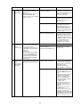
(Note 2) Error status output function on the heat source unit is enabled when Dip SW3-3 is set to OFF.
When Dip SW3-3 is set to ON, signal is output when heat source unit is stopped and water temperature (TH6) goes below 5˚C.
(Note 3) Operation-ON signal is output while the compressor is in operation if Dip SW2-7 is set to OFF.
If Dip SW2-7 is set to OFF, signal is output while receiving cooling or heating operation signal from the remote
controller.
(Signal output is continued even if the compressor comes to a stop due to Thermo OFF.)
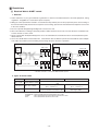
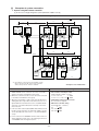
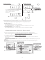
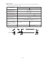
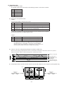
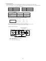
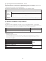
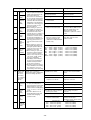
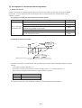
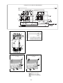
Terminals
■CN51
■CN3D
Remote controller board
Lamp power supply
L1
L2
Relay circuit
X
X
Y
Y
Adapter
5
4
3
Controller board on
Heat source unit
Remote controller board
Relay circuit
SW1
CN51
Adapter
X
1
2
Y
3
X
SW2
Y
Controller board on
Heat source unit
Field-installed
Field-installed
Maximum allowable wiring length = 10 m
Maximum allowable wiring length = 10 m
SW1 : Night mode command or step command
SW2 : Compressor ON/OFF command
X,Y : Relay (Contact Minimum applied load 12V DC 1 mA)
L1 : Error indicator lamp/freeze prevention output
L2 : Compressor operation display lamp
X,Y : Relay (For 12V DC coil rating 0.9 W or below)
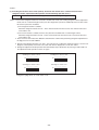
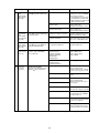
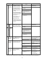
■TB8
■TB8
Heat source unit
TB8
Short3
circuit
4
CN3D
jumper
wire
63PW
With connection to pump interlock circuit
Remove the jumper wire when pump interlock circuit signal
connection is made to 3 or 4 of TB8.
63PW:Pressure switch (Contact: Minimum applied load 5 mA)
- 21 -
Heat source unit
TB8
1
X
2
52P
X : Relay (Contact rating 219~240V AC 1 A)
52P : Contactor for pump
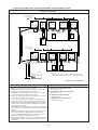
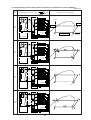
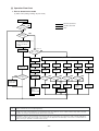
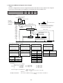
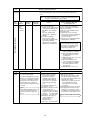
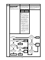
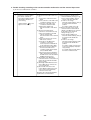
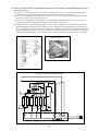
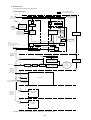
[3]
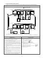
Examples of system connection
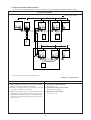
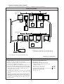
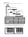
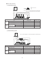
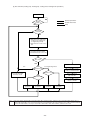
1. System using MA remote controller
(1) In the case of single refrigerant system (Automatic address set-up)
Control wiring example
Interlocking with ventilation
L1
L3
L2
Group
Group
OC
✻1
00
BC
IC
LC
IC
00
00
00
TB02
M1M2 S
TB5
TB15
M1M2 S 1 2
TB5
TB15
M1M2 S 1 2
00
TB5
M1M2 S
m1
TB7
TB3
M1M2 S M1M2
L4
A1 B2
✻1
A1 B2
A1 B2
RC
MA
NO
MA
M1M2 S
NO
00
L11
TB02
L12
BS
Group
L13
Group
IC
IC
00
00
00
TB15
TB5
M1M2 S 1 2
TB5
TB15
M1M2 S 1 2
TB5
TB15
M1M2 S 1 2
m5
m4
m2
IC
NO
A1 B2
A1 B2
A1 B2
A1 B2
MA
MA
MA
MA
✻1 BC and BS are found only in the R2 and WR2 systems.
When connected to the BS, indoor-outdoor automatic
address start up function will not be available.
– Example to use shielded wire –
Prohibited items
1. M-NET and MA remote controllers can not be connected together to the indoor unit within the same group.
2. MA remote controller of 3 units or more can not be connected
to the indoor unit within the same group.
3. When the total number of indoor units exceeds 26 units Including that above Type 200, a transmission booster is required. When the transmission booster is used, BC and BS
cannot be connected to TB3 (indoor unit side) on the transmission booster.
4. In the case when start/stop input (CN32, CN51, CN41) is used
by indoor group operation, the “Automatic address set-up”
can not be employed. Please refer to 1. (2) “ Manual address
set-up.”
5. For the connection of LOSSNAY with more than 2 units in a
single refrigerant system, refer to the following “Connection
of 2 LOSSNAY units in refrigerant system.”
m3
Allowable length
a. Indoor/outdoor transmission line
Farthest length (1.25mm2 or more)
≤ 200m
L1 + L2 + L3 + L4
L1 + L2 + L11 + L12 + L13 ≤ 200m
b. Centralized control transmission line
No connection is required.
c. MA remote controller wiring
Total length (0.3 ~ 1.25mm2)
≤ 200m
m1
m2 + m3 ≤ 200m
m4 + m5 ≤ 200m
- 22 -
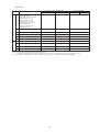
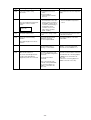
Wiring method • Address setting method
a. Indoor/outdoor transmission line
Daisy-chain the M1 and M2 terminals of the indoor-outdoor transmission terminal block (TB3) on the outdoor (heat
source) unit (OC), M1 and M2 terminals of the indoor-outdoor transmission line terminal block (TB02) on the BC
controller (BC), and M1 and M2 terminals of the indoor-outdoor transmission line terminal block (TB5) on each indoor
unit. (with non-polarity two wires)
❉ When the transmission line is long or noise sources are located near the unit, recommend to use shielded wire.
Connection of shielded wire:
For the earth of shielded wire, apply jumper wiring connection between the earth screw of OC and the S-terminal of
IC terminal block (TB5).
b. Centralized control transmission line
Connection is not required.
c. MA remote controller wiring
Connect the 1, 2 terminals of MA remote controller wiring terminal block (TB15) on IC to the terminal block of MA
remote controller (MA). (with non-polarity two wires)
❉ MA remote controller can be connected to A-type indoor unit or later.
For 2-remote controller operation:
To employ 2-remote controller operation, connect 1, 2 terminals of the terminal block (TB15) on IC to the terminal
block of two MA remote controllers.
❉ Set the main/sub selector switch of one MA remote controller to the sub remote controller. (For the setting method,
see the installation manual of MA remote controller.)
For indoor group operation:
For the group operation of IC, connect 1, 2 terminals of the terminal block (TB15) on all ICs within the same group,
and connect 1, 2 terminals of the terminal block (TB15) on another IC to the terminals of MA remote controller.
(with non-polarity two wires)
❉ To operate the indoor units with different function in the same group, refer to 1. (2).
d. LOSSNAY connection
Apply jumper wiring to connect M1, M2 terminals of the terminal block (TB5) on IC to the indoor/outdoor
transmission terminal block (TB5) on LOSSNAY (LC). (with non-polarity two wires)
❉ Linked and registered automatically with all indoor units within a refrigerant system.
❉ Please refer to the 1. (2) “Manual address set-up,” when interlocking partial indoor units with Lossnay, using
Lossnay alone without interlocking, interlocking indoor units and Lossnay for over 16 units within a refrigerant
system, or connecting LOSSNAY for over 2 units in a refrigerant system.
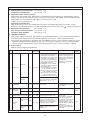
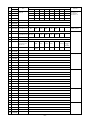
e. Switch setting
Address setting is not required.
Main unit
1
Address
setting range
Unit or controller
Order
IC
Not required
–
LC
Not required
–
MA
Not required
–
Sub unit
Set with main/sub
selector switch.
Not required
–
Indoor unit
Sub unit
2
LOSSNAY
3
MA remote
controller
Main unit
Sub unit
IC
MA
4
Outdoor (Heat source) unit
OC
5
Auxiliary
units
BC
BC controller
Setting method
- 23 -
Caution
Factory
setting
• Branch number setting is required by
R2 and WR2 systems.
• Refer to 1. (2) to operate indoor units
with different function in the same
group.
00
00
Main
00
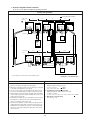
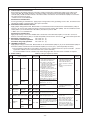
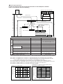
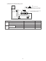
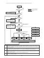
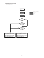
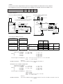
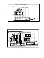
1. System using MA remote controller
(2) In the case of single refrigerant system connecting 2 or more LOSSNAY units (Manual address set-up)
Control wiring example
Interlocking with ventilation
L1
L3
L2
L4
Group
Group
OC
✻1
51
IC
LC
IC
52
01
02
TB02
M1M2 S
TB5
TB15
M1M2 S 1 2
TB5
TB15
M1M2 S 1 2
M1M2 S
TB02
53
✻1
05
TB5
M1M2 S
A1 B2
A1 B2
MA
MA
L11
TB3
TB7
M1M2 S M1M2
BC
L12
BS
L13
Group
IC
IC
LC
03
04
06
TB5
TB15
M1M2 S 1 2
TB5
TB15
M1M2 S 1 2
TB5
M1M2 S
A1 B2
MA
✻1. BC and BS are found only in the R2 and WR2 systems.
– Example to use shielded wire –
Prohibited items
1. M-NET and MA remote controllers can not be connected together to the indoor unit within the same group.
2. MA remote controller of 3 units or more can not be connected
to the indoor unit within the same group.
3. When the total number of indoor units exceeds 26 units including that above Type 200, a transmission booster is required. When the transmission booster is used, BC and BS
cannot be connected to TB3 (indoor unit side) on the transmission booster.
Allowable length
a. Indoor/outdoor transmission line
The same as 1. (1)
b. Centralized control transmission line
No connection is required.
c. MA remote controller wiring
The same as 1. (1)
- 24 -
Wiring method • Address setting method
a. Indoor/outdoor transmission line
The same as 1. (1)
Connection of shielded wire:
The same as 1. (1)
b. Centralized control transmission line
No connection is required.
The same as 1. (1)
c. MA remote controller wiring
For 2-remote controller operation:
The same as 1. (1)
For indoor group operation:
The same as 1. (1)
d. LOSSNAY connection
Apply jumper wiring to connect M1, M2 terminals of the terminal block (TB5) on the indoor unit (IC) to the terminal
block (TB5) on Lossnay (LC). (with non-polarity two wires)
❉ The interlocking registration of the indoor unit and Lossnay from the remote controller is required. (For the registration method, see the installation manual of remote controllers.)
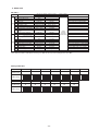
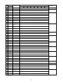
e. Switch setting
Address setting is required as listed below.
Order
Address
setting range
Unit or controller
Main unit
1
Indoor unit
IC
01 ~ 50
LOSSNAY
3
MA remote
controller
4
Set any address after setting all
indoor units.
LC
01 ~ 50
Main unit
MA
Not required
–
Sub unit
MA
Not required
Set with main/sub selector switch.
Factory
setting
• When operating indoor
units with different function
within a same group, assign the indoor unit with the
most plenty of function to
the main unit.
• Requires a branch-number setting.
00
OC
51 ~ 100
• Set the address not to be
overlapped with the indoor
unit address.
00
Main
Outdoor (Heat source) unit
BC Controller
(sub)
5
• Set the lowest address within
a same group to the indoor unit
desired to be the main unit.
• The address of the indoor unit
connected to the sub BC controller must be larger than that
of the indoor unit connected to
the main BC controller.
• If applicable, set the sub BC
controllers in an R2 system in
the following order:
(1) Indoor unit to be connected
to the main BC controller
(2) Indoor unit to be connected
to No.1 sub BC controller
(3) Indoor unit to be connected
to No.2 sub BC controller
Set the address so that (1) < (2) < (3)
Caution
Set to the main unit address within a same group in serial order
[Main unit +1, +2, +3, .... ]
Sub unit
2
Setting method
BS
Auxiliary
units
52 ~ 100
BC Controller
(main)
BC
The lowest address of indoor unit • To set the address to “100,”
set it to “50”.
within refrigerant system + 50
• If the address of main BC
Use the address that equals the controller overlaps with the
sum of the smallest indoor unit
address of the outdoor
address out of all the indoor
(heat source) unit or the
sub BC controller, use an
units that are connected to the
unused address within the
sub BC controller and 50.
setting range.
• The use of a sub BC conOutdoor (Heat source) unit
troller requires a main BC
address +1
controller.
- 25 -
00
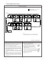
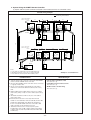
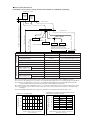
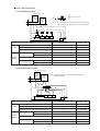
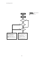
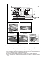
1. System using MA remote controller
(3) In the case of different refrigerant grouping operation
Control wiring example
Interlocking with ventilation
CN41→CN40
Replace
L1
L2
L3
Group
OC
✻1
51
IC
IC
LC
52
01
03
06
TB02
M1M2 S
TB5
TB15
M1M2 S 1 2
TB5
TB15
M1M2 S 1 2
BC
TB5
M1M2 S
m2
TB7
TB3
M1M2 S M1M2
L4
Group
Connect
A1 B2
MA
MA
M1M2 S
TB02
m3
A1 B2
L31
53
✻1
L21
Leave CN41
as it is.
OC
L22
L23
L24
Group
✻1
BC
54
55
TB7
TB3
M1M2 S M1M2
NO
BS
TB02
M1M2 S
IC
IC
IC
02
04
05
TB5
TB15
M1M2 S 1 2
TB5
TB15
M1M2 S 1 2
TB5 TB15
M1M2 S 1 2
NO
A1 B2
MA
✻1. BC and BS are found only in the R2 and WR2 systems.
– Example to use shielded wire –
Prohibited items
1. M-NET and MA remote controllers can not be connected together to the indoor unit within the same group.
2. MA remote controller of 3 units or more can not be connected
to the indoor unit within the same group.
3. Do not connect together the terminal blocks (TB5) of the indoor unit connected to different outdoor (heat source) units.
4. Replacement of the power supply selecting connector (CN41)
on the outdoor (heat source) unit should be done only on one
outdoor (heat source) unit.
5. Grounding of S-terminal of the centralized control terminal
block (TB7) on outdoor (heat source) unit should be done
only on one outdoor (heat source) unit.
6. When the total number of indoor units exceeds 26 units including that above Type 200, a transmission booster is required. When the transmission booster is used, BC and BS
cannot be connected to TB3 (indoor unit side) on the transmission booster.
Allowable length
a. Indoor/outdoor transmission line
Farthest length (1.25mm2 or more)
≤ 200m
L1 + L2 + L3 + L4
L21 + L22 + L23 + L24 ≤ 200m
b. Centralized control transmission line
Farthest length via outdoor (heat source) unit
(1.25mm2 or more)
L1 + L2 + L3 + L4 + L31 + L21 + L22 + L23 + L24 ≤ 500m
c. MA remote controller wiring
The same as 1. (1)
- 26 -
Wiring method • Address setting method
a. Indoor/outdoor transmission line
Daisy-chain the M1 and M2 terminals of the indoor-outdoor transmission terminal block (TB3) on the outdoor (heat
source) unit (OC), M1 and M2 terminals of the indoor-outdoor transmission line terminal block (TB02) on the BC
controller (BC), and M1 and M2 terminals of the indoor-outdoor transmission line terminal block (TB5) on each indoor
unit. (with non-polarity two wires)
❉ Make sure to use shielded wire.
The same as 1. (1)
Connecting of shielded wire:
b. Centralized control transmission line
Apply jumper wiring between M1, M2 terminals of centralized control transmission line terminal blocks (TB7) on
each OC. For one OC only, replace the power selecting connector (CN41) with (CN40).
❉ Make sure to use shielded wire.
Connecting of shielded wire:
Apply jumper wiring to connect the shielded earth to S-terminal of the terminal block (TB7) on each OC. Connect Sterminal of the terminal block (TB7) on the one OC with (CN40) replaced to the earth screw (
c. MA remote controller wiring
For 2-remote controller operation:
The same as 1. (1)
For indoor unit group operation:
The same as 1. (2)
d. LOSSNAY connection
The same as 1. (2)
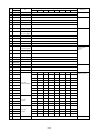
e. Switch setting
Address setting is required as follows.
Address
setting range
Unit or controller
Order
Main unit
1
Indoor unit
IC
01 ~ 50
LOSSNAY
3
MA remote
controller
4
• Set the lowest address within
a same group to the indoor unit
desired to be the main unit.
• The address of the indoor unit
connected to the sub BC controller must be larger than that
of the indoor unit connected to
the main BC controller.
• If applicable, set the sub BC
controllers in an R2 system in
the following order:
(1) Indoor unit to be connected
to the main BC controller
(2) Indoor unit to be connected
to No.1 sub BC controller
(3) Indoor unit to be connected
to No.2 sub BC controller
Set the address so that (1) < (2) < (3)
Set any address after setting all
indoor units.
LC
01 ~ 50
Main unit
MA
Not required
–
Sub unit
MA
Not required
Set with main/sub selector switch.
Caution
Factory
setting
• When operating indoor
units with different function
within a same group, assign the indoor unit with the
most plenty of function to
the main unit.
• Requires a branch-number setting.
00
OC
51 ~ 100
• Set the address not to be
overlapped with the indoor
unit address.
00
Main
Outdoor (Heat source) unit
BC Controller
(sub)
5
Setting method
Set to the main unit address within a same group in serial order
[Main unit +1, +2, +3, .... ]
Sub unit
2
) of the electrical parts box.
The same as 1. (1)
BS
Auxiliary
units
52 ~ 100
BC Controller
(main)
BC
• To set the address to “100,”
set it to “50”.
• If the address of main BC
Use the address that equals the controller overlaps with
sum of the smallest indoor unit
the address of the outdoor
address out of all the indoor
(heat source) unit or the
units that are connected to the
sub BC controller, use an
sub BC controller and 50.
unused address within the
setting range.
• The use of a sub BC conOutdoor (Heat source) unit
troller requires a main BC
address +1
controller.
The lowest address of indoor unit
within refrigerant system + 50
- 27 -
00
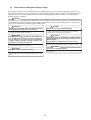
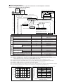
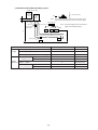
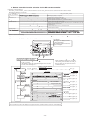
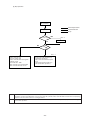
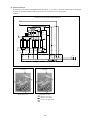
1. System using MA remote controller
(4) In the case of connecting system controller to centralized control transmission line
Control wiring example
Interlocking with ventilation
CN41→CN40 Replace
SW2-1 OFF→ON
L1
L2
Note 1
L3
Group
OC
✻1
51
TB7
TB3
M1M2 S M1M2
BC
L4
Group
IC
LC
IC
52
01
07
TB02
M1M2 S
TB5
TB15
M1M2 S 1 2
TB5
TB15
M1M2 S 1 2
05
TB5
M1M2 S
Connect
A1 B2
A1 B2
MA
MA
M1M2 S
TB02
L31
57
✻1
Leave CN41 as it is.
SW2-1 OFF→ON
NO
BS
L21
L22
Note 1
OC
L23
L24
Group
✻1
BC
53
TB7
TB3
M1M2 S M1M2
IC
IC
54
03
04
TB02
M1M2 S
TB5
TB15
M1M2 S 1 2
TB5
TB15
M1M2 S 1 2
LC
06
TB5
M1M2 S
NO
L32
A1 B2
MA
Note 2
System controller
Notes:
1. Leave SW2-1 as “OFF” when connecting LM adapter only.
2. LM adapter requires the power source of 1-phase AC 230V.
M1M2 S
✻1. BC and BS are found only in the R2 and WR2 systems.
– Example to use shielded wire –
Prohibited items
Allowable length
1. M-NET and MA remote controllers can not be connected together to the indoor unit within the same group.
2. MA remote controller of 3 units or more can not be connected
to the indoor unit within the same group.
3. Do not connect together the terminal blocks (TB5) of the indoor unit connected to different outdoor (heat source) units.
4. Replacement of the power supply selecting connector (CN41)
on the outdoor (heat source) unit should be done only on
one outdoor (heat source) unit.
5. Grounding work is required for S-terminal of the centralized
control transmission block (TB7) on one outdoor (heat source)
unit only.
6. When the total number of indoor units exceeds 26 units Including that above Type 200, a transmission booster is required. When the transmission booster is used, BC and BS
cannot be connected to TB3 (indoor unit side) on the transmission booster.
a. Indoor/outdoor transmission line
The same as 1. (3)
b. Centralized control transmission line
Farthest length via outdoor (heat source) unit
(1.25m m2 or more)
≤ 500m
L32 + L31 + L1 + L2 + L3 + L4
≤ 500m
L32 + L21 + L22 + L23 + L24
L1 +L2 + L3 + L4 + L31 + L21 + L22 + L23 + L24 ≤ 500m
c. MA remote controller wiring
The same as 1. (1)
- 28 -
Wiring method • Address setting method
a. Indoor/outdoor transmission line The same as 1. (3)
Connection of shielded wire:
The same as 1. (1)
b. Centralized control transmission line
Apply jumper wiring between M1, M2 terminals of centralized control transmission line terminal blocks (TB7) on
each OC. On one OC only, replace the power selecting connector (CN41) with (CN40). Set the centralized control
switch (SW2-1) on the main board of all outdoor (heat source) units to “ON.”
❉ Make sure to use shielded wire.
Connection of shielded wire:
Apply jumper wiring to connect the shielded earth to S-terminal of the terminal block (TB7) on each OC. Connect
S-terminal of the terminal block (TB7) on one OC with (CN40) connected to the earth screw ( ) of the electrical parts box.
c. MA remote controller wiring
The same as 1. (1)
For 2-remote controller operation: The same as 1. (1)
For indoor group operation:
The same as 1. (1)
d. LOSSNAY connection
Apply jumper wiring to connect M1, M2 terminals of the terminal block (TB5) on (IC) to the terminal block (TB5) on
the indoor/outdoor transmission line terminal block (TB5) on Lossnay (LC). (with non-polarity two wires)
❉ The interlocking registration of the indoor unit and LOSSNAY from the system controller is required. (For the
registration method, see the installation manual of the system remote controllers.) When connecting ON/OFF
remote controller and LM adaptor only, the interlocking registration from the remote controller is required.
e. Switch setting
Address setting is required as listed below.
Address
setting range
Unit or controller
Order
Main unit
1
Indoor unit
IC
01 ~ 50
LOSSNAY
3
MA remote
controller
4
Set any address after setting all
indoor units.
LC
01 ~ 50
Main unit
MA
Not required
–
Sub unit
MA
Not required
Set with main/sub selector switch.
Factory
setting
• When operating indoor
units with different function
within a same group, assign the indoor unit with the
most plenty of function to
the main unit.
• Requires a branch-number setting.
00
OC
51 ~ 100
• Set the address not to be
overlapped with the indoor
unit address.
00
Main
Outdoor (Heat source) unit
BC Controller
(sub)
5
• Set the lowest address within
a same group to the indoor unit
desired to be the main unit.
• The address of the indoor unit
connected to the sub BC controller must be larger than that
of the indoor unit connected to
the main BC controller.
• If applicable, set the sub BC
controllers in an R2 system in
the following order:
(1) Indoor unit to be connected
to the main BC controller
(2) Indoor unit to be connected
to No.1 sub BC controller
(3) Indoor unit to be connected
to No.2 sub BC controller
Set the address so that (1) < (2) < (3)
Caution
Set to the main unit address within a same group in serial order
[Main unit +1, +2, +3, .... ]
Sub unit
2
Setting method
BS
Auxiliary
units
52 ~ 100
BC Controller
(main)
BC
• To set the address to “100,”
set it to “50”.
• If the address of main BC
Use the address that equals the controller overlaps with
sum of the smallest indoor unit
the address of the outdoor
(heat source) unit or the
address out of all the indoor
sub BC controller, use an
units that are connected to the
unused address within the
sub BC controller and 50.
setting range.
• The use of a sub BC conOutdoor (Heat source) unit
troller requires a main BC
address +1
controller.
The lowest address of indoor unit
within refrigerant system + 50
- 29 -
00
1. System using MA remote controller
(5) Connecting (multiple) BC controllers in R2 and WR2 systems (with the system controller connected to the transmission lines for centralized control)
Control wiring example
Numbers in the squares indicate pipe-end
connection number.
Connection to the BC controller
CN41→CN40 Replace
SW2-1 OFF→ON
L1
Note 1
L3
L2
L4
Group
L5
L6
Group
L7
L9
L8
Group
L10
Group
OC
BC
51
IC
2
1
01
52
TB3
TB7
M1M2 S M1M2
IC
1
02
TB5
TB15
M1M2 S 1 2
TB02
M1M2 S
BS
IC
2
2
04
TB5
TB15
M1M2 S 1 2
IC
2
1
07
57
TB5
TB15
M1M2 S 1 2
08
TB5
TB15
M1M2 S 1 2
TB02
M1M2 S
BS
IC
1
2
IC
2
1
61
TB5
TB15
M1M2 S 1 2
TB02
M1M2 S
11
IC
1
TB5
TB15
M1M2 S 1 2
12
2
TB5
TB15
M1M2 S 1 2
Connect
L31
Leave CN41 as it is.
SW2-1 OFF→ON
L21
A1 B2
A1 B2
A1 B2
A1 B2
MA
MA
MA
MA
L22
L23
L24
Group
L25
L26
Group
NO
L27
Group
OC
BC
53
IC
3 2
1
54
TB3
TB7
M1M2 S M1M2
L32
TB02
M1M2 S
03
IC
1
TB5
TB15
M1M2 S 1 2
05
IC
2
TB5
TB15
M1M2 S 1 2
06
BS
3
IC
4
59
TB5
TB15
M1M2 S 1 2
TB02
M1M2 S
09
IC
4
TB5
TB15
M1M2 S 1 2
A1 B2
A1 B2
A1 B2
MA
MA
MA
10
4
TB5
TB15
M1M2 S 1 2
Note 2
System controller
M1M2 S
Notes:
1. Leave SW2-1 as “OFF” when connecting LM adapter only.
2. LM adapter requires the power source of 1-phase AC 230V.
– Example to use shielded wire –
Prohibited items
Allowable length
1. M-NET and MA remote controllers can not be connected together to the indoor unit within the same group.
2. MA remote controller of 3 units or more can not be connected
to the indoor unit within the same group.
3. Do not connect together the terminal blocks (TB5) of the indoor unit connected to different outdoor (heat source) units.
4. Replacement of the power supply selecting connector (CN41)
on the outdoor (heat source) unit should be done only on one
outdoor (heat source) unit.
5. Grounding work is required for S-terminal of the centralized
control transmission block (TB7) on one outdoor (heat source)
unit only.
6. When the total number of indoor units exceeds 26 units Including that above Type 200, a transmission booster is required. When the transmission booster is used, BC and BS
cannot be connected to TB3 (indoor unit side) on the transmission booster.
a. Indoor/outdoor transmission line
Farthest length (1.25mm2 or more)
L1 + L2 + L3 + L4 + L5 + L6 + L7 + L8 + L9 + L10
L21 + L22 + L23 + L24 + L25 + L26 + L27
b. Centralized control transmission line
Farthest length via outdoor (heat source) unit
(1.25m m2 or more)
L32 + L31 + L1 + L2 + L3 + L4 + L5 + L6+ L7 + L8 + L9 + L10
L32 + L21 + L22 + L23 + L24 + L25 + L26 + L27
L1 + L2 + L3 + L4 + L5 + L6 + L7 + L8 + L9 + L10
+ L31 + L21 + L22 + L23 + L24 + L25 + L26 + L27
c. MA remote controller wiring
The same as 1. (1)
- 30 -
≤ 200m
≤ 200m
≤
≤
500m
500m
≤
500m
Wiring method • Address setting method
a. Indoor/outdoor transmission line
Connect terminals M1 and M2 of the indoor-outdoor transmission line terminal block (TB3) on the outdoor (heat
source) unit (OC) to the terminals M1 and M2 of the indoor-outdoor transmission terminal block (TB02) of the main
BC controller (BC) and the sub BC controller (BS) and terminals M1 and M2 of the indoor-outdoor transmission terminal block (TB5) on each indoor unit (IC).
❉ Make sure to use shielded wire.
Connection of shielded wire:
The same as 1. (1)
b. Centralized control transmission line
The same as 1. (4)
Connection of shielded wire
The same as 1. (4)
c. MA remote controller wiring
The same as 1. (1)
For 2-remote controller operation:
The same as 1. (1)
For indoor group operation:
The same as 1. (1)
d. LOSSNAY connection
The same as 1. (4)
e. Switch setting
Address setting is required as listed below.
Order
Address
setting range
Unit or controller
Main unit
1
IC
Indoor unit
01 ~ 50
LOSSNAY
3
MA remote
controller
4
LC
01 ~ 50
Main unit
MA
Not required
Sub unit
MA
Sub unit
Outdoor (Heat source) unit
BC Controller
(sub)
5
OC
51 ~ 100
BS
Auxiliary
units
52 ~ 100
BC Controller
(main)
Caution
• Assign the smallest address
• R2 and WR2 types require
within the group to the indoor
a branch number setting.
unit to become the main unit.
• The address of the indoor unit
connected to the sub BC controller must be larger than that
of the indoor unit connected to
the main BC controller.
• If applicable, set the sub BC
controllers in an R2 system in
the following order:
(1) Indoor unit to be connected
to the main BC controller
(2) Indoor unit to be connected
to No.1 sub BC controller
(3) Indoor unit to be connected
to No.2 sub BC controller
Set the address so that (1) < (2) < (3)
Factory
setting
00
Set to the main unit address within a same group in serial order
[Main unit +1, +2, +3, .... ]
Sub unit
2
Setting method
BC
Set any address after setting all
indoor units.
• Set the address not to be
overlapped with the indoor
unit address.
00
• Using the system controller,
make the same indoor group
setting that was made with
Set with main/sub selector switch. the MA remote controller.
Main
The lowest address of indoor unit • To set the address to “100,”
set it to “50”.
within refrigerant system + 50
• If the address of main BC
Use the address that equals the controller overlaps with
sum of the smallest indoor unit
the address of the outdoor
address out of all the indoor
(heat source) unit or the
units that are connected to the
sub BC controller, use an
sub BC controller and 50.
unused address within the
setting range.
• The use of a sub BC conOutdoor (Heat source) unit
troller requires a main BC
address +1
controller.
00
–
- 31 -
1. System using MA remote controller
(6) In the case of connecting system controller to indoor/outdoor transmission line (excluding LM adaptor)
Control wiring example
Interlocking with ventilation
CN41→CN40 Replace
SW2-1 OFF→ON
L1
L2
L3
OC
✻1
51
TB3
TB7
M1M2 S M1M2
BC
L4
Group
Group
IC
LC
IC
52
01
07
TB02
M1M2 S
TB5
TB15
M1M2 S 1 2
TB5
TB15
M1M2 S 1 2
05
TB5
M1M2 S
Connect
A1 B2
A1 B2
MA
MA
M1M2 S
TB02
L31
57
✻1
Leave CN41 as it is.
SW2-1 OFF→ON
NO
BS
L21
L22
L23
L24
Group
OC
✻1
53
TB7
TB3
M1M2 S M1M2
BC
IC
IC
54
03
04
TB02
M1M2 S
TB5
TB15
M1M2 S 1 2
TB5
TB15
M1M2 S 1 2
LC
06
TB5
M1M2 S
L25
NO
Note 1
A1 B2
System controller
M1M2 S
MA
✻1. BC and BS are found only in the R2 and WR2 systems.
Note 1. LM adaptor may not be connected to indoor/outdoor transmission line.
Prohibited items
– Example to use shielded wire –
Allowable length
1. M-NET and MA remote controllers can not be connected together to the indoor unit within the same group.
2. MA remote controller of 3 units or more can not be connected
to the indoor unit within the same group.
3. Do not connect together the terminal blocks (TB5) of the indoor unit connected to different outdoor (heat source) units.
4. Replacement of the power supply selecting connector (CN41)
on the outdoor (heat source) unit should be done only on one
outdoor (heat source) unit.
5. Grounding work is required for S-terminal of the centralized
control transmission block (TB7) on one outdoor (heat source)
unit only.
6. The system controller connectable to the indoor/outdoor transmission line counts for 3 sets maximum. While G-50 counts
for only 1 set
7. When the total number of indoor units exceeds 26 sets, the
system controller may not be connected to the indoor/outdoor transmission line.
8. When the total number indoor units exceed 18 sets and they
includes Type 200 or above, the system controller may not
a. Indoor/outdoor transmission line
Farthest length (1.25mm2 or more)
≤ 200m
L1 + L2 + L3 + L4
L21 + L22 + L23 + L24 ≤ 200m
≤ 200m
L25
b. Centralized control transmission line
Farthest length via outdoor (heat source) unit
(1.25mm2 or more)
≤ 500m
L25 + L31 + L1 + L2 + L3 + L4
L1 + L2 + L3 + L4 + L31 + L21 + L22 + L23 + L24 ≤ 500m
c. MA remote controller wiring
The same as 1. (1)
be connected to the indoor/outdoor transmission line.
- 32 -
Wiring method • Address setting method
a. Indoor/outdoor transmission line
Daisy-chain the M1 and M2 terminals of the indoor-outdoor transmission terminal block (TB3) on the outdoor (heat
source) unit (OC), M1 and M2 terminals of the indoor-outdoor transmission line terminal block (TB02) on the BC
controller (BC), and M1 and M2 terminals of the indoor-outdoor transmission line terminal block (TB5) on each indoor
unit. (with non-polarity two wires)
❉ Make sure to use shielded wire.
Connection of shielded wire:
For the grounding of shielded wire, apply jumper wiring between the grounding screw of OC, S-terminal of the
terminal block (TB3), and S-terminal of the system controller.
b. Centralized control transmission line
Apply jumper wiring between M1, M2 terminals of centralized control transmission line terminal blocks (TB7) on
each OC. On one OC only, replace the power selecting connector (CN41) with (CN40). Set the centralized control
switch (SW2-1) on the main board of all outdoor (heat source) units to “ON.”
❉ Make sure to use shielded wire.
Connection of shielded wire:
Apply jumper wiring to connect the shielded earth to S-terminal of the terminal block (TB7) on each OC. Connect Sterminal of the terminal block (TB7) on one OC with (CN40) connected to the earth screw ( ) of the electrical parts box.
The same as 1. (1)
c. MA remote controller wiring
For 2-remote controller operation: The same as 1. (1)
The same as 1. (2)
For indoor unit group operation:
d. LOSSNAY connection
Apply jumper wiring to connect M1, M2 terminals of the terminal block (TB5) on (IC) to the terminal block (TB5) on
the indoor/outdoor transmission line terminal block (TB5) on Lossnay (LC). (with non-polarity two wires)
❉ The interlocking registration of the indoor unit and Lossnay is required from the system controller. (For the
registration method, see the instruction manual of system controller.)
To connect ON/OFF remote controller only, interlocking registration from the remote controller is required.
e. Switch setting
Address setting is required as follows.
Address
setting range
Unit or controller
Order
Main unit
1
Indoor unit
IC
01 ~ 50
LOSSNAY
3
MA remote
controller
4
5
Set any address after setting all
indoor units.
LC
01 ~ 50
Main unit
MA
Not required
Sub unit
MA
Not required
Set with main/sub selector switch.
Factory
setting
• When operating indoor units
with different function within a
same group, as-sign the
indoor unit with the most
plenty of function to the main
unit.
• Requires a branch-number
setting.
00
OC
51 ~ 100
The lowest address of indoor unit
within refrigerant system + 50
52 ~ 100
Use the address that equals the
sum of the smallest indoor unit address out of all the indoor units that
are connected to the sub BC controller and 50.
• Set the address not to be
overlapped with the indoor
unit address.
00
–
Main
Outdoor (Heat source) unit
Auxiliary
units
• Set the lowest address within a
same group to the indoor unit
desired to be the main unit.
• The address of the indoor unit
connected to the sub BC
controller must be larger than that
of the indoor unit connected to
the main BC controller.
• If applicable, set the sub BC
controllers in an R2 system in the
following order:
(1) Indoor unit to be connected to
the main BC controller
(2) Indoor unit to be connected to
No.1 sub BC controller
(3) Indoor unit to be connected to
No.2 sub BC controller
Set the address so that (1) < (2) < (3)
Caution
Set to the main unit address within a
same group in serial order
[Main unit +1, +2, +3,....]
Sub unit
2
Setting method
BC Controller
(sub)
BC Controller
(main)
BS
BC
Outdoor (Heat source) unit
address +1
- 33 -
• To set the address to “100,”
set it to “50”.
• If the address of main BC controller overlaps with the address of the outdoor (heat
source) unit or the sub BC controller, use an unused address within the setting range.
• The use of a sub BC controller
requires a main BC controller.
00
2. System Using the M-NET Remote Controller
(1) System with the system controller connected to the transmission lines for centralized control
Control wiring example
Interlocking with ventilation
CN41→CN40 Replace
SW2-1 OFF→ON
L1
L2
L3
OC
✻1
51
TB3
TB7
M1M2 S M1M2
BC
L4
Group
Group
Note1
IC
LC
IC
52
01
07
TB02
M1M2 S
TB5
TB15
M1M2 S 1 2
TB5
TB15
M1M2 S 1 2
05
TB5
M1M2 S
Connect
A1 B2
A1 B2
101
102
RC
RC
M1M2 S
TB02
L31
57
✻1
Leave CN41 as it is.
SW2-1 OFF→ON
L21
Note1
OC
53
TB3
TB7
M1M2 S M1M2
NO
BS
L23
L22
L24
Group
✻1
BC
IC
IC
54
03
04
TB02
M1M2 S
TB5
TB15
M1M2 S 1 2
TB5
TB15
M1M2 S 1 2
LC
06
TB5
M1M2 S
L32
NO
Note 2
System controller
A1 B2
M1M2 S
103
RC
Notes:
1. Leave SW2-1 as “OFF” when connecting LM adapter only.
2. LM adapter requires the power source of 1-phase AC 230V.
✻1. BC and BS are found only in the R2 and WR2 systems.
– Example to use shielded wire –
Prohibited items
1. A group of indoor units cannot be connected to both M-NET
remote controller and MA remote controllers.
2. No more than 2 M-NET remote controllers can be connected
to a group of indoor units.
3. Do not connect the TB5’ s (Terminal block) of the indoor
units that are connected to different outdoor (heat source)
units.
4. Replace CN41 (power supply switch connector on outdoor
(heat source) units) on only one of the outdoor (heat source)
units.
5. Ground the S terminal of TB7 on only one of the outdoor
(heat source) units.
6. Transmission line booster is necessary when the total
number of connected indoor units exceeds 20 (19 with 1 BC
and 18 with 1 BC and BS each). When the transmission
booster is used, BC and BS cannot be connected to TB3
(indoor unit side) on the transmission booster.
7. Transmission line booster is necessary if the system
includes indoor units of 200 or higher and the total number
of indoor units exceeds 16 (15 with 1 BC and 14 with 1 BC
and BS each).
Allowable length
a. Indoor/outdoor transmission line
The same as 1. (3)
b. Centralized control transmission line
The same as 1. (4)
c. M-NET remote controller wiring
The same as 2. (1)
- 34 -
Wiring method • Address setting method
a. Indoor/outdoor transmission line
The same as 1. (3)
Connection of shielded wire:
The same as 1. (1)
b. Centralized control transmission line
The same as 1. (4)
Connection of shielded wire:
c. M-NET remote controller wiring
The same as 1. (4)
M-NET remote controller wiring
Connect each of the M1 and M2 terminals of TB5 (indoor/outdoor transmission line terminal block) on the IC to
the terminals on the M-NET remote controller.
For 2-remote controller operation:
For a 2-remote-controller operation, connect each of the terminals M1 and M2 of the IC terminal block to the two
RC terminal blocks respectively.
For indoor unit group operation:
Indoor unit group operation
To operate IC’s as a group, connect the M1, M2 terminals of the terminal block on the main IC in the group with
the RC terminal block (with non-polar two wires)
❉M-NET remote controller can be connected at any point on the indoor/outdoor transmission line.
❉To run a group operation of indoor units that have different functions, select the unit with the greatest number
of functions as the main unit.
d. LOSSNAY connection
The same as 1. (4)
e. Switch setting
Address setting is required as follows.
Order
Address
setting range
Unit or controller
Main unit
1
IC
Indoor unit
01 ~ 50
LOSSNAY
3
M-NET
remote
controller
4
• The Lossnay address must not
After all indoor units have received
overlap with the indoor unit
an address, use any remaining
address.
number and assign it to the Lossnay
unit. units.
01 ~ 50
Main unit
RC
101 ~ 150
The address of the main unit in the
same group +100
Sub unit
RC
151 ~ 200
OC
51 ~ 100
BC Controller
(sub)
5
• Assign the smallest address within • Make the initial setting of the
indoor unit group setting with
the group to the indoor unit to
the system controller
become the main unit.
(MELANS).
• Assign a larger address to the
indoor unit that is connected to the • Branch numbers must be set
for systems with R2 and WR2.
R2-type sub BC controller than the
one assigned to the indoor unit
connected to the main BC
controller.
• If applicable, set the sub BC controllers in an R2 system in the following order:
(1) Indoor unit to be connected to
the main BC controller
(2) Indoor unit to be connected to
No.1 sub BC controller
(3) Indoor unit to be connected to
No.2 sub BC controller
Set the address so that (1) < (2) < (3)
LC
Outdoor (Heat source) unit
BS
Auxiliary
units
52 ~ 100
BC Controller
(main)
Caution
Factory
setting
00
Starting with the number main unit
address +1, assign a sequential
number to each of the rest of the
indoor units.
Sub unit
2
Setting method
BC
00
The address of the main unit in the
same group +150
• 100’s digit does not need to be
set.
• Set the address to “ 00 ” when
setting it to “ 200 ”.
101
The smallest indoor unit address in
the same refrigerant system +50
• Set the address to “ 50 ” when
setting it to “ 100 ”.
00
Use the address that equals the
sum of the smallest indoor unit address out of all the indoor units that
are connected to the sub BC controller and 50.
• To set the address to “100,” set
it to “50”.
• If the address of main BC controller overlaps with the address of the outdoor (heat
source) unit or the sub BC controller, use an unused address
within the setting range.
• The use of a sub BC controller
requires a main BC controller.
00
Outdoor (Heat source) unit
address +1
- 35 -
3. System where MA remote controller and M-NET remote controller coexist
Control wiring example
CN41→CN40 Replace
SW2-1 OFF→ON
L1
L3
L2
Note1
Group
OC
✻2
51
TB3
TB7
M1M2 S M1M2
BC
L4
Group
IC
IC
IC
52
01
02
07
TB02
M1M2 S
TB5
TB15
M1M2 S 1 2
TB5
TB15
M1M2 S 1 2
TB5
TB15
M1M2 S 1 2
Connect
A1 B2
A1 B2
104
MA
RC
M1M2 S
TB02
L31
57
✻2
Leave CN41 as it is.
SW2-1 OFF→ON
NO
BS
L21
L22
Note1
L23
L24
Group
OC
✻2
53
TB3
TB7
M1M2 S M1M2
BC
Group
IC
IC
IC
54
03
05
06
TB02
M1M2 S
TB5
TB15
M1M2 S 1 2
TB5
TB15
M1M2 S 1 2
TB5
TB15
M1M2 S 1 2
NO
A1 B2
A1 B2
L32
105
MA
Note 2
RC
Notes:
1. Leave SW2-1 as “OFF” when connecting LM adapter only.
2. LM adapter requires the power source of 1-phase AC 230V.
System controller
M1M2 S
– Example to use shielded wire –
Prohibited items
Allowable length
1. Make sure to connect the system controller.
2. M-NET and MA remote controllers can not be connected together to the indoor unit within a same group.
3. M-NET remote controller of 3 units or more can not be connected to the indoor unit within a same group.
4. MA remote controller of 3 units or more can not be connected
to the indoor unit within a same group.
5. Do not connect together the terminal blocks (TB5) of the indoor unit connected to different outdoor (heat source) units.
6. Replacement of the power supply selecting connector (CN41)
on the outdoor (heat source) unit should be done only on one
outdoor (heat source) unit.
7. Grounding work is required for S-terminal of the centralized
control transmission block (TB7) on one outdoor (heat source)
unit only.
8. When the total number of indoor units exceeds 20 sets, transmission line booster is required. When the transmission
booster is used, BC and BS cannot be connected to TB3
(indoor unit side) on the transmission booster.
9. When the total number of indoor units exceed 16 sets and
they include Type 200 or above, the transmission line booster
is required.
a. Indoor/outdoor transmission line
The same as 1. (3)
b. Centralized control transmission line
The same as 1. (4)
c-1. MA remote controller wiring
The same as 1. (1)
c-2. M-NET remote controller wiring
The same as 2. (1)
- 36 -
Wiring method • Address setting method
a. Indoor/outdoor transmission line
The same as 1. (3)
Connection of shielded wire:
The same as 1. (1)
b. Centralized control transmission line
The same as 1. (4)
Connection of shielded wire:
The same as 1. (4)
c-1. MA remote controller wiring, For 2-remote controller operation: , For indoor unit group operation:
The same as 1. (1)
c-2. M-NET remote controller, For 2-remote controller operation: , For indoor unit group operation:
The same as 2. (1)
d. Lossnay connection
The same as 1. (4)
e. Switch setting
Address setting is required as follows.
Order
1
Address
setting range
Unit or controller
Operation
with MA
remote
controller
Indoor
unit
Main
unit
IC
01 ~ 50
MA
2
01 ~ 50
Main unit address inside a same
101 ~ 150 group + 100
RC
151 ~ 200 group + 150
00
01 ~ 50
4
Outdoor (Heat source) unit
OC
51 ~ 100
BS
52 ~ 100
BC
• 100 digits are not required to set.
• When setting the address as
“200,” make it “00.”
101
Main unit address inside a same
LC
BC Controller
(main)
• After setting the address of the
• Initially set the same setting
indoor unit to be operated with MA detail as that of indoor unit group
controller, set the lowest address
with system controller.
among the same group to the
• Branch numbers must be set for
indoor unit desired to be the main
a system with R2.
unit.
• Assign a larger address to the
indoor unit that is connected to the
R2-type sub BC controller than the
one assigned to the indoor unit
connected to the main BC
controller.
RC
Lossnay
Auxiliary
units
–
Set to the main unit address within
a same group in serial order.
[Main unit +1, +2, +3,....]
3
5
00
Sub remote Set by using the main/sub selector
controller switch
Sub
unit
BC Controller
(sub)
Factory
setting
Main
MA
IC
Main
M-NET
unit
remote
controller Sub
unit
• Set the lowest address within a
• Set lower address than that of
same group to the indoor unit
the indoor unit connected to
desired to be the main unit.
M-NET remote controller.
• Assign a larger address to the
• Initially set the same setting
indoor unit that is connected to the detail as that of indoor unit group
R2-type sub BC controller than the executed in the wiring of MA
one assigned to the indoor unit
remote controller with system
connected to the main BC
controller.
controller.
• Branch numbers must be set for
• If applicable, set the sub BC consystems with R2 and WR2.
trollers in an R2 system in the following order:
(1) Indoor unit to be connected to
the main BC controller
(2) Indoor unit to be connected to
No.1 sub BC controller
(3) Indoor unit to be connected to
No.2 sub BC controller
Set the address so that (1) < (2) < (3)
Not
required
Main
unit
Indoor
unit
Operation
with M-NET
remote
ontroller
Caution
Set to the main unit address within
a same group in serial order.
[Main unit +1, +2, +3,....]
Sub
unit
Main
MA
unit
remote
controller Sub
unit
Setting method
After setting all indoor units, set any • Set so that not duplicating with
address.
the indoor unit addresses.
00
The lowest address of indoor unit
within refrigerant system + 50
• When setting the address to
“100,” make it “50.”
00
Use the address that equals the
sum of the smallest indoor unit address out of all the indoor units that
are connected to the sub BC controller and 50.
• To set the address to “100,” set it
to “50”.
• If the address of main BC controller overlaps with the address of
the outdoor (heat source) unit or
the sub BC controller, use an unused address within the setting
range.
• The use of a sub BC controller requires a main BC controller
00
Outdoor (Heat source) unit
address +1
- 37 -
[4]
Restrictions on Refrigerant Piping Length
For the piping connection, the end branching system is applied where the end of refrigerant piping from the heat source
unit is branched and connected to each indoor unit. As the piping connection method, the indoor unit is applied with flare
connection, heat source unit gas piping is flange connection, and liquid piping is flare connection. For the branching,
brazed connection is applied.
Warning
Be careful not to leak refrigerant gas (R410A) near a fire. Refrigerant gas if touched a fire of gas oven and the like will
be decomposed to generate poisonous gas leading to gas-poisoning. Do not conduct welding work in a closed room.
Run a gas leak test after completing refrigerant piping work.
Warning
Caution
Do not use a refrigerant other than that indicated on
the equipment at installation or movement.
Do not use existing refrigerant piping.
• The old refrigerant and refrigerator oil in the existing piping
contains a large amount of chlorine which may cause the
refrigerantor oil of the new unit to deteriorate.
• Mixing of different refrigerant or air makes the refrigeration cycle
abnormal causing breakage and the like.
Caution
Caution
Use refrigerant piping phosphorus deoxidized copper. In addition, be sure that the inner and outer surface of the pipes are clean and free of hazardous
sulphur, oxides, dust/dirt, shaving particles, oils,
moisture, or any other contaminant.
Store the piping to be used during installation indoors
and keep both ends of the piping sealed until just
before brazing.
(Store elbows and other joints in a plastic bag.)
• If dust, dirt, or water enters the refrigerant cycle,
deterioration of the oil and compressor trouble may result.
• Contaminants on the inside of the refrigerant piping may cause
the refrigerant residual oil to deteriorate.
Caution
Caution
Do not use a charging cylinder.
Use liquid refrigerant to fill the system.
• Using a charging cylinder may cause the refrigerant to
deteriorate.
• If gas refrigerant is used to seal the system, the composition of
the refrigerant in the cylinder will change and performance may
drop.
- 38 -
1. Line-branch method
■PQRY-P200,P250YGM-A
[16 branches or less (the use of only the main BC controller or standard BC controller)]
Heat
source
unit
A
H’ = 40 m or less (outdoor unit below)
BC controller
40 m or less
h1 = 15 m or less
Branch pipe (for Y-series)
CMY-Y102S-G
a
Indoor unit Junction b
pipe
(option)
h2 = 15 m or less
H = 50 m or less (outdoor unit above)
110 m or less
B
e
c
d
Indoor unit
Indoor unit
Indoor unit
(P141~P250 types: 2-line merge)
Maximum of 3 units per branch joint
Total capacity of P140 or less
(All units connected to the same
branch joint must be in the same mode.)
Indoor unit
Item
Piping length
Total piping length
Piping sections
Allowable value
A+B+a+b+c+d+e
300 m less (Note 2)
A+e
150 m or less
(175 m equivalent length or less)
A
110 m or less
Farthest piping length
Between heat source unit - BC controller
Height difference
Between BC controller and indoor unit
e
40 m or less (Note 3)
Between indoor unit
and heat source unit Heat source unit below
H
50 m or less
H’
40 m or less
Between indoor unit and BC controller
h1
15 m or less (10 m or less) (Note 1)
Between indoor units
h2
15 m or less (10 m or less) (Note 1)
Heat source unit above
Note 1: Use the figures in the parentheses if the capacity of the connected indoor units is P200 type or above.
Note 2: Refer to the graph below for restrictions on refrigerant piping length when the total piping length exceeds 300 m.
Note 3: Refer to the graph below for restrictions on refrigerant piping length when the piping length between the BC
controller and the farthest indoor unit exceeds 40 m. (except P250-type indoor units)
Note 4: When indoor units of P200 type or above are connected, neither branch joints nor branch headers can be used.
Note 5: Do not connect P200- or P250-type indoor units and other types of indoor units at the same pipe end connection.
• Height difference and branch piping length between
BC controller and indoor unit. (A)
• Restrictions on piping length
Piping length between main BC controller
and farthest indoor unit (m)
Total piping length (m)
400
350
300
250
200
30
40
50
60
70
80
90
100 110
Distance between heat source unit and
BC controller (m)
70
60
50
40
30
20
10
0
0
5
10
15
Height difference between main BC controller and
farthest indoor unit (m)
- 39 -
■PQRY-P200,P250YGM-A
[Systems that requires more than 16 pipe-end connections or with multiple BC controllers
(with a use of both main and sub controllers)]
<With more than 16 branching>
Heat
source
unit
Indoor unit
C
110 m or less
h3
A
H’ = 40 m or less (outdoor unit below)
Note 6
BC controller (main)
40 m or less
h1 = 15 m or less
h4
Branch pipe (for Y-series)
CMY-Y102S-G
a
Indoor unit Junction b
pipe
(option)
h2 = 15 m or less
H = 50 m or less (outdoor unit above)
Indoor unit
g
f
BC controller
(sub)
B
e
c
d
Indoor unit
Indoor unit
Indoor unit
(P141~P250 types: 2-line merge)
Maximum of 3 units per branch joint
Total capacity of P140 or less
(All units connected to the same
branch joint must be in the same mode.)
Indoor unit
Item
Piping sections
Piping length
Total piping length
A+B+C+a+b+c+d+e+f+g
300 m less
A + C + g or A + e
150 m or less
(175 m equivalent length or less)
A
110 m or less
e or C + g
40 m or less (Note 2)
H
50 m or less
Farthest piping length
Between heat source unit - BC controller
Between BC controller and indoor unit
Height difference
Between indoor unit
and heat source unit
Allowable value
Heat source unit above
Heat source unit below
H’
40 m or less
Between indoor unit and BC controller
h1
15 m or less (10 m or less) (Note 3)
Between indoor units
h2
15 m or less (10 m or less) (Note 3)
Between main BC controller and sub BC controller
h3
15 m or less
h4
15 m or less (10 m or less)
(Notes 3 and 5)
Between indoor (main BC controller) and
indoor (sub BC controller) units
Note: A system with more than 16 branching requires 2 to 3 BC controllers (main/sub) and 3 pipes between BC controllers.
Note 1: Refer to the graph below for restrictions on refrigerant piping when the total piping length exceeds 300 m.
Note 2: Refer to the graph below for restrictions on refrigerant piping length when the piping length between the BC
controller and the farthest indoor unit exceeds 40 m. (except P250-type indoor units)
Note 3: Use the figures in the parentheses if the capacity of the connected indoor units is P200 type or above.
Note 4: When indoor units of type P200 or above are connected, neither branch joints nor branch headers can be used.
Note 5: When 2 sub BC controllers are connected, include them in the figures in the table above.
Note 6: When 2 sub BC controllers are connected, connect them in parallel.
• Height difference and branch piping length between
• Restrictions on piping length
BC controller and indoor unit. (A)
Piping length between main BC controller
and farthest indoor unit (m)
Total piping length (m)
400
350
300
250
200
30
40
50
60
70
80
90
100 110
Distance between heat source unit and
BC controller (m)
70
60
50
40
30
20
10
0
0
5
10
15
Height difference between main BC controller and
farthest indoor unit (m)
- 40 -
■PQRY-P400,P500YSGM-A
[16 branches or less (the use of only the main BC controller or standard BC controller)]
(Heat source unit)
Heat
exchanger
unit
Compressor
unit
h3 h3’
110 m or less
D
H’ = 40 m or less (Compressor unit below)
BC controller
40 m or less
h1 = 15 m or less
Branch pipe (for Y-series)
CMY-Y102S-G
a
Indoor unit Junction b
pipe
(option)
h2 = 15 m or less
H = 50 m or less (Compressor unit above)
A
B
e
c
d
Indoor unit
Indoor unit
Indoor unit
(P141~P250 types: 2-line merge)
Maximum of 3 units per branch joint
Total capacity of P140 or less
(All units connected to the same
branch joint must be in the same mode.)
Indoor unit
Item
Piping length
Total piping length
Piping sections
Allowable value
A+B+D+a+b+c+d+e
300 m or less (Note 2)
A+D+e
150 m or less
(175 m equivalent length or less)
Farthest piping length
Between Compressor unit - BC controller
A+D
110 m or less
Between BC controller and indoor unit
e
40 m or less (Note 3)
Between Compressor unit and Heat exchanger unit
D
10 m or less (Note 5, Note 6)
Compressor unit above
H
50 m or less
Height difference
Between indoor unit
and Compressor unit
H’
40 m or less
Between indoor unit and BC controller
h1
15 m or less (10 m or less) (Note 1)
Between indoor units
Between Compressor unit
and Heat exchanger unit
Compressor unit below
h2
15 m or less (10 m or less) (Note 1)
Compressor unit above
h3
0m
Compressor unit below
h3’
10 m or less
Note 1: Use the figures in the parentheses if the capacity of the connected indoor units is P200 type or above.
Note 2: Refer to the graph below for restrictions on refrigerant piping length when the total piping length exceeds 300 m.
Note 3: Refer to the graph below for restrictions on refrigerant piping length when the piping length between the BC
controller and the farthest indoor unit exceeds 40 m. (except P250-type indoor units)
Note 4: When indoor units of P200 type or above are connected, neither branch joints nor branch headers can be used.
Note 5: Use optional extension wire for water-source unit to leave a space between the compressor unit and the heat
exchanger.
Note 6: The piping length between the compressor unit and the heat exchanger unit must be 10m or less.
• Height difference and branch piping length between
BC controller and indoor unit. (A)
• Restrictions on piping length
Piping length between main BC controller
and farthest indoor unit (m)
Total piping length (m)
400
350
300
250
200
30
40
50
60
70
80
90
100 110
Distance between heat source unit and
BC controller (m)
70
60
50
40
30
20
10
0
0
5
10
15
Height difference between main BC controller and
farthest indoor unit (m)
- 41 -
■PQRY-P400,P500YSGM-A
[Systems that requires more than 16 pipe-end connections or with multiple BC controllers
(with a use of both main and sub controllers)]
Heat
exchanger
unit
(Heat source unit)
<With more than 16 branching>
Compressor
unit
h3 h3’
Indoor unit
f
C
110 m or less
Indoor unit
g
BC controller
(sub)
Note 6
A
H’ = 40 m or less (Copressor unit below)
h4
BC controller (main)
40 m or less
h1 = 15 m or less
h5
Branch pipe (for Y-series)
CMY-Y102S-G
a
Indoor unit Junction b
pipe
(option)
h2 = 15 m or less
H = 50 m or less (Copressor unit above)
D
B
e
c
d
Indoor unit
Indoor unit
Indoor unit
(P141~P250 types: 2-line merge)
Maximum of 3 units per branch joint
Total capacity of P140 or less
(All units connected to the same
branch joint must be in the same mode.)
Indoor unit
Item
Piping length
Total piping length
Farthest piping length
Piping sections
Allowable value
A+B+C+D+a+b+c+d+e+f+g
300 m or less
A + C + D + g or A + e
150 m or less
(175 m equivalent length or less)
A+D
110 m or less
Between Compressor unit - BC controller
e or C + g
40 m or less (Note 2)
D
10 m or less (Note 7, Note 8)
Compressor unit above
H
50 m or less
Compressor unit below
H’
40 m or less
Between indoor unit and BC controller
h1
15 m or less (10 m or less) (Note 3)
Between indoor units
h2
15 m or less (10 m or less) (Note 3)
Between BC controller and indoor unit
Between Compressor unit and Heat exchanger unit
Height difference
Between indoor unit
and Compressor unit
Compressor unit above
h3
0m
Compressor unit below
h3’
10 m or less
Between main BC controller and sub BC controller
h4
15 m or less
h5
15 m or less (10 m or less)
(Note 3 and 5)
Between Compressor unit
and Heat exchanger unit
Between indoor unit (main BC controller) and
indoor unit (sub BC controller)
Note: A system with more than 16 branching requires 2 to 3 BC controllers (main/sub) and 3 pipes between BC controllers.
Note 1: Refer to the graph below for restrictions on refrigerant piping when the total piping length exceeds 300 m.
Note 2: Refer to the graph below for restrictions on refrigerant piping length when the piping length between the BC controller
and the farthest indoor unit exceeds 40 m. (except P250-type indoor units)
Note 3: Use the figures in the parentheses if the capacity of the connected indoor units is P200 type or above.
Note 4: When indoor units of type P200 or above are connected, neither branch joints nor branch headers can be used.
Note 5: When 2 sub BC controllers are connected, include them in the figures in the table above.
Note 6: When 2 sub BC controllers are connected, connect them in parallel.
Note 7: Use optional extension wire for water-source unit to leave a space between the compressor unit and the heat exchanger.
Note 8: The piping length between the compressor unit and the heat exchanger unit must be 10m or less.
• Restrictions on piping length
• Height difference and branch piping length between BC controller and indoor unit. (A)
Piping length between main BC controller
and farthest indoor unit (m)
Total piping length (m)
400
350
300
250
200
30
40
50
60
70
80
90
100 110
Distance between heat source unit and
BC controller (m)
70
60
50
40
30
20
10
0
0
5
10
15
Height difference between main BC controller and
farthest indoor unit (m)
- 42 -
■PQHY-P200,P250YGM-A
1 Line branching system
Heat
source
unit
To downstream unit
A
Note: The total model names downstream in the table below
represent that viewed from A-point in the above figure.
A
H
L
B
C
First branch a
h
Indoor
1
e
D
b
c
d
Indoor
2
Indoor
3
Indoor
4
Indoor
Item
Piping section
Total piping length
Length
Less than 300m
A+B+C+D+e
Less than 150m
B+C+D+e
Less than 40m
Upper heat source unit
H
Less than 50m
Lower heat source unit
H’
Less than 40m
h
Less than 15m
Farthest piping length (L)
Indoor
– Heat source
Allowable value
A + B + C + D + a + b + c + d +e
Farthest piping length after first branch ( )
Height
difference
5
Indoor – Indoor
2 Header branching system
Heat
source
unit
Note: The branch piping can not be branched again after header branching.
A
L
H
First branch
Cap
a
Indoor
h
1
b
Indoor
2
c
Indoor
3
d
Indoor Indoor
4
5
Item
6
A+a+b+c+d+e+f
Less than 300m
A+f
Less than 150m
f
Less than 40m
Upper heat source unit
H
Less than 50m
Lower heat source unit
H’
Less than 40m
h
Less than 15m
Farthest piping length (L)
Indoor
– Heat source
Indoor
Allowable value
Farthest piping length after first branch (
Height
difference
f
Piping section
Total piping length
Length
e
)
Indoor – Indoor
- 43 -
3 Mixed line and header branching system
To downstream unit
Heat
source
unit
A
Note: The total model names downstream in the table below
represent that viewed from A-point in the above figure.
A
Branch header
C
First branch
(Branch joint)
d
e
Indoor
3
Indoor
4
L
Indoor
5
h
H
B
Note: The branch piping can not be branched
again after header branching.
Cap
c
b
Branch joint
a
Indoor
2
Indoor 1
Item
Piping section
Allowable value
A+B+C+a+b+c+d+e
Less than 300m
A+B+b
Less than 150m
B+b
Less than 40m
Upper heat source unit
H
Less than 50m
Lower heat source unit
H’
Less than 40m
h
Less than 15m
Total piping length
Length
Farthest piping length (L)
Farthest piping length after first branch (
Height
difference
Indoor
– Heat source
)
Indoor – Indoor
- 44 -
■PQHY-P400,P500YSGM-A
1 Line branching system
(Heat source unit)
Heat
exchanger
unit
To downstream unit
A
Compressor
unit
h2
Note: The total model names downstream in the table below
represent that viewed from A-point in the above figure.
A
H
E
L
B
C
First branch a
h
Indoor
1
e
D
b
c
d
Indoor
2
Indoor
3
Indoor
4
Indoor
Item
Piping section
Total piping length
Length
Less than 300m
A+B+C+D+E+e
Less than 150m
B+C+D+e
Less than 40m
Upper Compressor unit
H
Less than 50m
Lower Compressor unit
H’
Less than 40m
h
Less than 15m
Upper Compressor unit
h2
Less than 0m
Lower Compressor unit
h2’
Less than 10m
Farthest piping length (L)
Indoor
– Compressor unit
Indoor – Indoor
Compressor unit
– Heat exchanger unit
Allowable value
A + B + C + D + E + a + b + c + d +e
Farthest piping length after first branch ( )
Height
difference
5
2 Header branching system
(Heat source unit)
Heat
exchanger
unit
h2
A
Note: The branch piping can not be branched again after
header branching.
Compressor
unit
E
L
H
First branch
Cap
a
Indoor
h
1
b
Indoor
2
c
Indoor
3
d
Indoor Indoor
4
5
Item
Less than 300m
A+f
Less than 150m
f
Less than 40m
Upper Compressor unit
H
Less than 50m
Lower Compressor unit
H’
Less than 40m
h
Less than 15m
Upper Compressor unit
h2
Less than 0m
Lower Compressor unit
h2’
Less than 15m
)
Indoor – Indoor
Compressor unit
– Heat exchanger unit
6
A+a+b+c+d+e+f
Farthest piping length after first branch (
Height
difference
Indoor
Allowable value
Farthest piping length (L)
Indoor
– Compressor unit
f
Piping section
Total piping length
Length
e
- 45 -
3 Mixed line and header branching system
(Heat source unit)
Heat
exchanger
unit
To downstream unit
Compressor
unit
h2
A
A
Note: The total model names downstream in the table below
represent that viewed from A-point in the above figure.
E
Branch header
C
First branch
(Branch joint)
Cap
c
d
e
Indoor
3
Indoor
4
L
Indoor
5
h
H
B
Note: The branch piping can not be branched
again after header branching.
b
Branch joint
a
Indoor
2
Indoor 1
Item
Piping section
Allowable value
A+B+C+a+b+c+d+e
Less than 300m
A+B+b
Less than 150m
B+b
Less than 40m
Upper Compressor unit
H
Less than 50m
Lower Compressor unit
H’
Less than 40m
h
Less than 15m
Upper Compressor unit
h2
Less than 0m
Lower Compressor unit
h2’
Less than 15m
Total piping length
Length
Farthest piping length (L)
Farthest piping length after first branch (
Indoor
– Compressor unit
Height
difference
)
Indoor – Indoor
Compressor unit
– Heat exchanger unit
- 46 -
2. Refrigerant piping size
<PQRY>
1 Between heat source unit and BC controller (Part A)
Heat source unit
PQRY-P200
YGM-A
PQRY-P250
YGM-A
High pressure
pipe
ø 15.88
ø 19.05
ø 22.2
Low pressure
pipe
ø 19.05
ø 22.2
ø 28.58
Item
Refrigerant piping
size
End connection
of heat source unit
and BC controller
PQRY-P400
YSGM-A
PQRY-P500
YSGM-A
High pressure
pipe
ø 15.88 (Brazed) ø 19.05 (Brazed)
ø 22.2 (Brazed)
Low pressure
pipe
ø 19.05 (Brazed) ø 22.2 (Brazed)
ø 28.58 (Brazed)
Note 1: Heat source units and BC controllers are supplied with flanges with a short copper pipe as a part used to
connect to the low pressure pipe.
2 Between BC controller and indoor unit (Parts a, b, c, d, and e)
Indoor unit
Item
Refrigerant piping
size
End connection
of indoor unit
(Flare connection
for all unit types)
20, 25, 32
40, 50
Liquid pipe
ø 6.35
Gas pipe
ø 12.7
Liquid pipe
ø 6.35
Gas pipe
ø 12.7
63, 71, 80, 100
125, 140
200
250
ø 9.52
ø 15.88
ø 19.05
ø 22.2
ø 9.52
ø 15.88
ø 19.05
ø 22.2
3 Between main BC controller and sub BC controller (Part C)
Indoor unit
Item
Liquid pipe
Refrigerant piping
size
High-pressure
(Use brazing for
Gas pipe
all units.)
Low-pressure
Liquid pipe
~P200
P201~P300
P301~P350
ø 9.52
ø 12.7
ø 15.88
ø 19.05
ø 19.05
ø 22.2
ø 28.58
✻ When 2 sub controllers are connected, determine the pipe size on the main side based
on the total capacity of the indoor units that are connected to the 2 sub controllers, and
determine the pipe size on the sub controller side based on the total capacity of the
units that are connected.
4 Compressor unit and Heat exchanger unit (Part D)
Heat source unit
Refrigerant pipe
size
PQRY-P200
YGM-A
PQRY-P250
YGM-A
PQRY-P400
YSGM-A
PQRY-P500
YSGM-A
Low-pressure
pipe
ø 28.58
High-pressure
pipe
ø 19.05
Bypass pipe
ø 9.52
Note 2: Use pipes that are specified in the section “Read Before Servicing: [3] Piping Materials.”
- 47 -
<PQHY>
A
(mm)
Outdoor model
P200
P250
P400
P500
*1 ø12.7 for over 90m
Liquid pipe
ø9.52
*1 ø9.52
Gas pipe
ø19.05
ø22.2
ø12.7
ø15.88
ø28.58
ø28.58
Downstream unit model total
~ 200
201 ~ 400
401 ~ 650
The 1st branch of P450 ~ P650
4-Branching header
(Downstream unit
model total 200)
CMY-Y104-G
Branch kit model
CMY-Y102S-G
CMY-Y102L-G
CMY-Y202-G
8-Branching header
(Downstream unit
model total 400)
CMY-Y108-G
10-Branching header
Downstream unit
model total 650)
CMY-Y1010-G
B, C, D
Total capacity of indoor units
~ 140
141 ~ 200
201 ~ 300
301 ~ 400
401 ~ 650
(mm)
Liquid pipe
ø9.52
ø9.52
ø9.52
ø12.7
ø15.88
Gas pipe
ø15.88
ø19.05
ø22.2
ø28.58
ø28.58
a, b, c, d, e
Model number
20,25,32,40,50
63,71,80,100,125,140
200
250
(mm)
Liquid pipe
ø6.35
ø9.52
ø9.52
ø9.52
Gas pipe
ø12.7
ø15.88
ø19.05
ø22.2
- 48 -
3. Connecting the BC controllers
<PQRY>
(1) BC controller (standard model) end connection piping size
[P200,P250 types]
Piping sections High-pressure side Low-pressure side
(liquid side)
(gas side)
ø 15.88
ø 19.05
PQRY-P200YGM-A
Heat
(Brazed)
(Brazed)
source
ø 22.2
ø 19.05
unit side PQRY-P250YGM-A
(Brazed)
(Brazed)
ø 9.52
ø 15.88
Indoor unit side
(Flare)
(Flare)
Item
End connection:
brazed connection
To heat source unit
✻ BC controllers (standard model) can only be connected to P200,P250
heat source units.
BC controller
✻2
Junction
pipe kit
(Type: CMYR160-J)
(option)
✻1
Reduce
(supplied)
Indoor unit
Indoor unit
Indoor unit
P50 type
or below
P63-P140
types
P200-P250
types
Branch pipe
(Type: CMY-Y102S-G)(option)
A
B
Indoor unit
Indoor unit
Indoor unit
✻3
Maximum of 3 units per branch joint
Total capacity of P140 or less
(All units connected to the same
branch joint must be in the same mode.)
The size of the branch end connection on the BC controller is designed to fit P50-P140 type indoor units.
To connect other types of indoor units, perform the following procedures.
✻1: To connect P20-P50 type indoor units
✻2: To connect P200 or P250 type indoor units
(or when the total capacity of the indoor units
exceeds P141)
Use the reducer that is supplied with the BC
controller
Use an optional junction pipe kit and merge the 2
joints
234
70
Liquid pipe side: 3/8F
(flare)
Liquid pipe side:
ø 6.35 ID
Gas pipe side: 5/8F
(flare)
Gas pipe side:
ø 12.7 ID
Liquid pipe side: 3/8F
(flare)
Gas pipe side: 5/8F
(flare)
Note: Use the flare nut provided with the BC controller
Liquid pipe side:
ø 9.52 ID
Gas pipe side:
ø 19.05 ID
(ø 22.2 with reducer)
Provided with a thermal
insulation cover
✻3: To connect multiple indoor units to a branch joint (or to a junction pipe)
1
2
3
4
Total capacity of connectable indoor units: P140 or below (P250 or below when a junction pipe is used)
The number of connectable indoor units: 3 max.
Branch pipe: Use Type CMY-Y102S-G (option)
Selection of refrigerant piping (pipe size of the A and B in the figure above): Use the total capacity of the
downstream indoor units to determine the proper pipe size, using the table below as a reference.
Total capacity of the indoor units
Liquid pipe
Gas pipe
P140 or below
ø 9.52
ø 15.88
P141~P200
ø 9.52
ø 19.05
P201~P250
ø 9.52
ø 22.2 (❈)
(❈) With reducer
- 49 -
(2) BC controller (main) end connection piping size
End connection:
brazed connection
To heat source unit
Main BC controller
✻2
Junction pipe kit
(Type: CMY-R160-J)
(option)
✻1
Reducer
(supplied)
A
Indoor unit
Indoor unit
Indoor unit
P50 type
or below
P63-P140
types
P200-P250
types
Branch pipe (Type: CMY-Y102S-G)
(For CITY MULTI Y series, option)
B
Indoor unit
Indoor unit
Indoor unit
Maximum of 3 units per branch joint.
Total capacity of P140 or less
(All units connected to the same
branch joint must be in the same mode.)
The size of the branch end connection on the BC controller is designed to fit P63-P140 type indoor units.
To connect other types of indoor units, perform the following procedures.
✻1: To connect P20-P50 type indoor units, use the reducer that is supplied with the BC controller
✻2: To connect P200 or P250 type indoor units (or when the total capacity of the indoor units exceeds P141),
use an optional junction pipe kit (Type: CMY-R160-J) and merge the 2 joints.
✻3: To connect multiple indoor units to a branch joint (or to a junction pipe)
• Total capacity of connectable indoor units : P140 or below (P250 or below when a junction pipe is used)
• The number of connectable indoor units : 3 max.
• Selection of refrigerant piping (pipe size of the A and B in the figure above)
: Use the total capacity of the downstream indoor units to determine the proper pipe size, using the
table below as a reference.
Total capacity of the indoor units
Liquid pipe
Gas pipe
P140 or below
ø 9.52
ø 15.88
P141~P200
ø 9.52
ø 19.05
P201~P250
ø 9.52
ø 22.2 (❈)
(❈) With reducer
Piping sections
Item
PQRY-P200YGM-A
Heat
source
unit side
PQRY-P250YGM-A
PQRY-P400YSGM-A
PQRY-P500YSGM-A
Indoor unit side
High-pressure side Low-pressure side
(liquid side)
(gas side)
ø 15.88
ø 19.05
(Brazed)
(Brazed)
ø 19.05
ø 22.2
(Brazed)
(Brazed)
ø 22.2
(Brazed)
ø 28.58
(Brazed)
ø 9.52
(Flare)
ø 15.88
(Flare)
- 50 -
(3) BC controller (sub) end connection piping size
End connection:
brazed connection
Main BC controller
Sub BC controller
✻2
Junction pipe kit
(Type: CMY-R160-J)
(option)
✻1
Reducer
(supplied)
A
Indoor unit
Indoor unit
Indoor unit
P50 type
or below
P63-P140
types
P200-P250
types
Branch pipe (Type: CMY-Y102S-G)
(For CITY MULTI Y series, option)
B
Indoor unit
Indoor unit
Indoor unit
Maximum of 3 units per branch joint.
Total capacity of P140 or less
(All units connected to the same
branch joint must be in the same mode.)
The size of the branch end connection on the BC controller is designed to fit P63-P140 type indoor units.
To connect other types of indoor units, perform the following procedures.
✻1: To connect P20-P50 type indoor units, use the reducer that is supplied with the BC controller
✻2: To connect P200 or P250 type indoor units (or when the total capacity of the indoor units exceeds P141),
use an optional junction pipe kit (Type: CMY-R160-J) and merge the 2 joints.
✻3: To connect multiple indoor units to a branch joint (or to a junction pipe)
• Total capacity of connectable indoor units : P140 or below (P250 or below when a junction pipe is used)
• The number of connectable indoor units : 3 max.
• Selection of refrigerant piping (pipe size of the A and B in the figure above) :
Use the total capacity of the downstream indoor units to determine the proper pipe size, using the
table below as a reference.
Total capacity of the indoor units
Liquid pipe
Gas pipe
P140 or below
ø 9.52
ø 15.88
P141~P200
ø 9.52
ø 19.05
P201~P250
ø 9.52
ø 22.2 (❈)
(❈) With reducer
Piping sections
Item
Total capacity of indoor units
connected to applicable BC controller
High-pressure side Low-pressure side
(liquid side)
(gas side)
ø 15.88
(Brazed)
P200 type and below
BC
controller P201-P300 types
side
ø 19.05
(Brazed)
P301 types and above
- 51 -
ø 19.05
(Brazed)
ø 22.2
(Brazed)
ø 28.58
(Brazed)
Liquid side
ø 9.52
(Brazed)
ø 12.7
(Brazed)
£ Components of the Heat source Unit
[1] Appearance of the Components and Refrigerant Circuit
< PQRY-P200, P250 >
Sub box
Control box
Heat exchanger
4-way valve
Solenoid
valve
(SV7a~7c)
Check valve block
Solenoid valve block
Compressor
Accumulator
- 52 -
< PQHY-P200, P250 >
Subcool coil
Sub box
Control box
Heat exchanger
4-way valve
Check valve block
Solenoid valve block
Compressor
Accumulator
- 53 -
< PQRY-P400, P500 (Compressor unit) >
< PQHY-P400, P500 (Compressor unit) >
✻This unit is both for PQHY and PQRY.
Sub box
Control box
Relay cable connector
(Compressor unit Heat exchanger unit)
Compressor
Accumulator
- 54 -
< PQRY-P400, P500 (Heat exchanger unit) >
Heat exchanger
Solenoid valve block 1
4-way valve
Relay cable connector
(Compressor unit Heat exchanger unit)
Solenoid valve block 2
Solenoid valve
(SV7a~7c)
Check valve block 1
Check valve block 2
- 55 -
< PQHY-P400, P500 (Heat exchanger unit) >
Heat exchanger
Solenoid valve block 1
4-way valve
Relay cable connector
(Compressor unit Heat exchanger unit)
Solenoid valve block 2
Solenoid valve
(SV7a~7c)
Check valve block 1
Check valve block 2
Subcool coil
- 56 -
[2] Control Box
[ Appearance ]
INV board
Main board
Transmission line
terminal block
for centralized control
(TB7)
Choke coil
(L1, L2)
Filter board
Power supply terminal
block (TB1)
Indoor/outdoor
transmission
terminal block
(TB3)
[ Under the circuit board cover ]
ACCT-U
ACCT-W
IPM
DCCT
DCL (back)
Smoothing capacitor
(C11, C12)
Gate amp board
(G/A board)
Rush current
protection resistor
(R11, R12)
Diode stack (DS)
Electromagnetic contactor
(52C1)
Noise filter
Transmission line
terminal block
for centralized control
(TB7)
Power supply
terminal block
(TB1)
Indoor/outdoor
transmission terminal block
(TB3)
- 57 -
[ Sub box ]
Relay board
Pump interlock input
Operation-ON signal output terminal block
(TB8)
- 58 -
[3] Circuit Board
1. Main board
LD2
CNRS3B
CNRS3A
CNS1 CNS2
CN40
CN38
CN41
CNVCC1
Controlled
source input
1 – 2 DC30V
1 – 3 DC30V
4 – 5 DC7V
4 – 6 DC12V
7 – 8 DC7V
CNRT1
CN52C
Control for
52C1
CN51
3–4
CN63PW
Compressor
ON/OFF
CN3N
3–5
CN3D
Trouble
CN3S
CNOUT1
CNLVC
CNAC3
Power output
3 L1
1 L2
CNLVB
CN20
Power input
5 L1
CN21
Power input
3 L2
1N
LD1
Service LED
SW5
SW4 SW3
SWU2
- 59 -
SW2
SWU1 SW1
2. INV board
CNVDC
F02
CN15V2
Power supply
for IPM control
SW1
CNVCC1
Power supply
1 – 2 DC30V
1 – 3 DC30V
4 – 5 DC7V
4 – 6 DC12V
7 – 8 DC7V
SW2
CN52C
CNDR2
CNAC2
Power input
5 L2
3N
1G
CNCT
CNTH
CNFAN
CNRS1
CNRS2
Serial
transmission
for MAIN board
- 60 -
CNCT2
3. Filter board
CNFG
CNOUT
Controlled
source output
CNL1
CNIN
Controlled
source input
CNL2
4. G/A board
CNDC1
CNDC2
CN15V1
CNIPM1
CNDR1
- 61 -
5. Relay board (Heat source unit)
CN81
Solenoid valve output
for unit control (200V)
CN83
1 - 3 Operation-ON signal output
5 - 7 Pump interlock input
CNAC4
Power input
4 R-phase
1 S-phase
CNOUT2
Relay drive input from
main circuit board
- 62 -
CNPW
1 - 2 Pump interlock signal output
to main circuit board
[4] BC controller (inside the panel)
< CMB-P
V-G(A) >
[ Front (CMB-P1016V-G(A) is shown in the picture) ]
Gas pipe
(indoor unit side)
Liquid pipe
(indoor unit side)
LEV1
TH11
TH16
PS1
LEV2
SVM2
SVM1
PS3
TH12
LEV2
PS3
TH15
LEV3
TH11
SVM1
High-pressure side (Heat source unit side)
PS1 LEV1
SVM2
✻ No SVM2 on G type
< CMB-P1016V-G >
- 63 -
LEV3
[ Rear view (CMB-P1016V-G(A) is shown in the picture) ]
< CMB-P1016V-G >
Gas-liquid separator
Tube-in-tube heat exchanger
< CMB-P1016V-GA >
Tube-in-tube heat exchanger
Gas-liquid separator
- 64 -
< CMB-P
V-GB>
[ Front view (CMB-P104V-GB is shown in the picture) ]
[ Rear view (CMB-P104V-GB is shown in the picture) ]
TH22
LEV3a
TH25
- 65 -
[5] BC control box
[ BC controller control box (CMB-P1016V-GA is shown in the picture) ]
Relay board
Transformer
Terminal block
for power supply
Terminal block
for transmission
BC controller board
[6] BC controller board
[ BC controller board ]
SW4
SW5
SW2
- 66 -
SW1
[ Relay board (RELAY 4 board) ]
[ Relay board (RELAY 10 board) ]
- 67 -
¢ Remote Controller
[1] Functions and Specifications of MA and ME Remote Controllers
There are two types of remote controllers: M-NET (ME) remote controller, which is connected
on the indoor/outdoor transmission line, and MA remote controller, which is connected to
each indoor unit.
1. Comparison of Functions and Specifications of MA and ME Remote Controllers
Function/specification
Remote controller address setting
MA remote controller (Notes 1, 4)
Not required
M-NET(ME)Remote Controller (Notes 2, 4)
Required
Indoor/outdoor unit address Not required (required only by a system
setting
with one outdoor unit)(Note 3)
Required
Wiring method
Non-polar 2 wires
✻ Daisy-chain the indoor units with non-polar
2 wires when running a group operation.
Non-polar 2 wires
Installation location of
remote controller
Connectable to any indoor unit in the
group
Connectible at any point on the
indoor/outdoor transmission line
Interlocking with the
ventilation unit
Each indoor unit can individually be
interlocked with a ventilation unit.
(Registered on the remote controller in
the same group)
Each indoor unit can individually be
interlocked with a ventilation unit.
(Registered on the remote controller)
Making group changes
MA remote controller wires between
indoor units require rewiring.
Indoor unit and remote controller
addresses must be changed, or the
registration information must be changed
using MELANS.
(Note 1)
(Note 2)
(Note 3)
(Note 4)
MA remote controller includes MA remote controllers, MA compact remote controllers, and wireless remote controllers.
M-NET remote controller includes ME remote controllers and compact remote controllers.
Depending on the system configuration, even a single refrigerant system may require an address setting.
Either an MA remote controller or an M-NET remote controller can be connected to a group of multiple-refrigerant systems
or when a system controller is connected.
2. Selecting the Best Type of Remote Controller
Select either the MA remote controller or the M-NET remote controller to take full advantage of a given system.
The following information is provided as a reference for selection.
MA remote controller (Notes 1, 2)
M-NET (ME) remote controller (Notes 1, 2)
• Low chances of system expansion and grouping
changes are expected.
• Grouping (floor plan) has been decided at the
time of installation.
• High chances of centralized installation of remote
controllers, system expansion, and grouping changes.
• Grouping (floor plan) has not been decided at the
time of installation.
• Direct connection of the remote controller to the
Lossnay inside the heater-humidifier.
(Note 1) M-NET remote controllers and MA remote controllers cannot both be connected to the same group of indoor units.
(Note 2) A system controller must be connected to a system that has both MA remote controllers and M-NET remote controllers.
< A system using an MA remote controller >
Outdoor unit
Group
MA remote controller
< System using an M-NET remote controller >
M-NET transmission line
(indoor/outdoor transmission line)
Outdoor unit
Group
M-NET transmission line
(indoor/outdoor transmission line)
Group
Indoor unit
M-NET remote controller
- 68 -
Group
Indoor unit
[2] Group Setting and Interlocking Settings that are Made on an ME Remote Controller
1. Group setting/interlocking setting
Make the following settings to perform a group operation of units that are connected to different outdoor units or to manually set up the
indoor/outdoor unit address.
(A) Group settings...........Registration of the indoor units to be controlled with the remote controller,
and search and deletion of registered information.
(B) Interlock settings........Registration of LOSSNAY units to be interlocked with the indoor units,
and search and deletion of registered information
[Operation Procedures]
(1) Address settings
1 Bring up either one of the following displays on the remote controller:
TEMP.
normal display, which appears when the unit is stopped. The display window must
look like one of the two figures below to proceed to the next step.
C
ON/OFF
FILTER
CLOCK ON
G
P
PAR-F27ME
TIMER SET
D
E
[Blinking display of HO ]
B
H
[Normal display]
(A) Group Settings
F
A
CHECK TEST
(B) Interlock Settings
window.
6
buttons
B
A
]
G
Press again to go back to the Group Setting window as shown
under step
.
shown below.
Both the indoor unit address and
interlocked unit address will be
displayed together.
Indoor unit address display window
Interlocked unit
Indoor unit
address
address
display window display window
3 Select the unit address.
C [SET TEMP. (
) or (
To search for an address,
go to section (2) Address Search.
7 Bring up the address of the indoor unit and the address of the
)] to advance or go back
LOSSNAY to be interlocked on the display.
- Select the address of the indoor unit to be registered by pressing
button C [SET TEMP. ( ) or ( )] to advance or go back through
4
display.
D
- Select the address of the LOSSNAY unit to be interlocked by
H
- If registration is successfully completed, unit type will appear
on the display as shown in the figure below.
- If the selected address does not have a corresponding indoor
unit, an error message will appear on the display. Check the
address, and try again.
<Successful completion of registration>
8 Make the settings to interlock LOSSNAY units with indoor
units.
- Press button D [TEST] while both the indoor unit address and
the address of the LOSSNAY units to be interlocked
are displayed to enter the interlock setting.
Unit type (Indoor unit in this case)
LOSSNAY address in the indoor unit address display
<Deletion error>
address display window.
If registration is successfully
completed, the two displays as
shown on the left will appear
alternately.
corresponding unit.)
(Displayed alternately)
5 To register the addresses for multiple indoor units, repeat
steps
and
above.
will blink on the display.
(Indicates that the selected
address does not have a
corresponding unit.)
To search for an address,
go to section (2) Address Search.
NOTE :
- 69 -
Interlock all the indoor units in the group with the
LOSSNAY units; otherwise, the LOSSNAY units will
not operate.
9
(C) To return to the normal display
When all the group settings and interlock settings are made, take the
To search for an address,
go to section (2) Address Search.
B
A
1
(2) Address search
To search for the address of indoor units that have been entered into
the remote controller, follow steps 1 and 2 .
(A) To search group settings
(B) Interlock setting search
proceed as follows:
11 Bring up the Group Setting window.
- Each pressing of button E [TIMER ] will bring up the address of a
registered indoor unit and its unit type on the display.
the display.
- Select the address of the indoor unit to be searched by pressing
button H [TIMER SET ( ) or ( )] to advance or go back
through the interlocked addresses.
<Entry found>
Unit type
(Indoor unit in this case)
LOSSNAY can be searched in the same manner by bringing up
the LOSSNAY address in the Interlocked unit address display window.
<No entries found>
1
13
E
- When only one unit address is registered, the same address
will remain on the display regardless of how many times the
button is pressed.
E
LOSSNAY and indoor unit that is interlocked with it will be
displayed alternately.
[TIMER ] .
Address of an interlocked
LOSSNAY unit
(Displayed alternately)
1 Bring up the address of another registered unit on the
14
To delete an address, go to
section (3) Address Deletion.
display.
E
unit.
(The display method is the same as the one in step
.)
To go back to the normal display,
Address of another
interlocked unit
(Displayed alternately)
To delete an address,
go to section (3) Address Deletion .
(3) Address deletion
The addresses of the indoor units that have been entered into the remote controller can be deleted by deleting the group settings.
The interlock settings between units can be deleted by deleting the interlock settings.
Follow the steps in section (2) Address Search to find the address to be deleted and perform deletion with the address being displayed in the
display window. To delete an address, the address must first be bought up on the display.
Delete the registered indoor unit address or the interlock setting between units.
F
display to delete the interlock setting.
- 70 -
(A) To delete group settings
(B) To delete interlock settings
<Successful completion of deletion>
If deletion is successfully
completed,
will appear in
(Displayed alternately)
will be displayed in the room temperature display window.
- If a transmission error occurs, the selected setting will not be
deleted, and the display will appear as shown below.
In this case, repeat the steps above.
window. In this case, repeat the
steps above.
<Deletion error>
will be displayed in the room temperature display window.
To go back to the normal display, follow step
.
(4) Making (A) Group settings and (B) Interlock settings of a group from any arbitrary remote controller
(A) Group settings and (B) Interlock settings of a group can be made from any arbitrary remote controller.
Refer to (B) Interlock Settings under section 1 Group Settings/Interlock Settings for operation procedures.
Set the address as shown below.
(A) To make group settings
Interlocked unit address display window...Remote controller address
Indoor unit address display window...........The address of the indoor unit to be controlled with the remote controller
(B) To make interlock settings
Interlocked unit address display window...LOSSNAY address
Indoor unit address display window..........The address of the indoor unit to be interlocked with the LOSSNAY
2. Remote controller functions selection via the ME remote controller
In the remote controller function selection mode, the settings for three types of functions can be made or changed as necessary.
1) Operation mode display selection mode (Display
p y or non-display
p y of COOL/HEAT during
g automatic operation
p
mode))
When the automatic operation mode is selected, the indoor unit will automatically perform a cooling or heating operation based on the room
temperature. In this case, AUTO COOL or AUTO HEAT will appear on the remote controller display.
This setting can be changed so that only AUTO will appear on the display.
2) Room temperature display selection mode (Display or non-display of room temperature)
Although the suction temperature is normally displayed on the remote controller, the setting can be changed so that it will not appear on the
remote controller.
3) Narrowed preset temperature range
g mode
The default temperature ranges are 19 C to 30 C in the cooling/dry mode and 17 C to 28 C in the heating mode.
By changing these ranges (raising the lower limit for the cooling/dry mode and lowering the upper limit for the heating mode), energy can be saved.
NOTE
On the PAR-F27MEA-F model, automatic operation mode cannot be selected while the unit is in the narrowed preset temperature range mode.
Only the lower limit can be set for cooling/dry mode, and upper limit for heating mode.
[Function selection mode sequence on the remote controller]
R
Remote
t controller
t ll function
f nction
ti selection
l ti modes
d
UT
mode setting
[Normal display]
*2
2
ange limit mode (AUTO)
ON/OFF
3
CLOCK ON OFF
FILTER
5
Oper
CHECK TEST
PAR-F27MEA
UT
TIMER SET
4
1
for two seconds.
y selection mode
mode display)
*1
Set temperature range limit mode (cool/dry)
(
button
) ] button
*1: Skip AUTO mode selected.
*2: Include AUTO mode selected.
ange limit mode (Heat)
Room temperature display selection mode
- 71 -
[Operation Procedures]
1. Press the [ON/OFF] button on the remote controller to bring the unit to a stop. The display will appear as shown in the previous page (Normal
display).
1
3
2
under the remote controller function selection mode.
Skip AUTO mode setting (when you want to skip AUTO
UT
“
”
switched.
“
”
“OFF”” lights.
.
) or (
[Time selection (
) or (
)] buttons
“
” display is
)] button
Include AUTO mode selected.
• When ON
•
”
are pressed in this state, the “ON”
Skip AUTO mode selected.
mode can be selected using the mode selection button.
O
utton and automatic operation is not possible.
utton, AUTO mode is skipped.)
Press button
1Hr.
CENTRALLY CONTROLLED
[TIMER SET (
TEST RUN
LIMIT TEMP.
[TIMER SET (
) ((
))] button
STAND BY
DEFROST
)] in this
1Hr.
CENTRALLY CONTROLLED
DEFROST
) or (
NOT AVAILABLE
TEST RUN
LIMIT TEMP.
Room temperature display selection mode (Display or non-display of room temperature)
4
in this state to switch between ON and OFF.
DRY
DRY
SENSAOR
INSIDE
[TIMER SET (
STAND BY
DEFROST
SENSAOR
INSIDE
TIMER
) ((
))] button
FILTER
CHECK MODE
TEST RUN
LIMIT TEMP.
STAND BY
DEFROST
When it is set to ON, the room temperature will stay in the operation display window during operation.
When it is set to OFF, the room temperature will not appear in the operation display window during operation.
Narrowed preset temperature range mode (The range of preset temperature can be changed.)
1) Temperature range setting for the cooling/dry mode
[Selection range for the lower limit temperature] : 19 C
30 C (Medium temperature range indoor unit 14 C
30 C)
SENSAOR
INSIDE
STAND BY
DEFROST
[When the temperature range for the cooling or dry mode is set to 24 C to 30 C]
2) Press button [TIMER SET ( ) or ( )] to set the lower limit temperature to the desired temperature.
TIMER
CHECK
STAND BY
DEFROST
[When the temperature range is changed to 24 C - 30 C]
3) After completing the step above, press button
range for the heating operation.
[SET TEMP. (
)] to go into the temperature range setting mode to set the temperature
4
Medium temperature range indoor unit 17 C
vailab
“
UT
.
ange for AU O
UT
mode operation.
yed.
Y mode temper ature
mode temperature r
] and [
])
[Lower limit temper
28
[Upper limit temperature adjustment range]:
C
C (*2) (Can be adjusted as lo
*2: Mid temperature indoor units have a lower limit temperature of 17 C.
pressing and holding buttons
28 C)
[CHECK] and [MODE] simultaneously for 2 seconds.
- 72 -
y
y
.)
wer limit temperature.)
[3] Interlocking Setting via the MA Remote Controller
1. Lossnay interlocking setting (Make this setting only when necessary)
Make this setting only when necessary.
*When an upper controller is connected, make the settings on the upper controller.
NOTE : To perform an interlocked operation with LOSSNAY units, interlock all the indoor units in the group with the LOSSNAY units.
Perform this operation to enter the interlock setting between the LOSSNAY and the indoor units to which the remote controller is connected, or to
search and delete registered information.
In the following example, the address of the indoor unit is 05 and the address of the LOSSNAY unit is 30.
[Operation Procedures]
- The indoor unit address and the interlocked LOSSNAY address will appear alternately.
<Indoor unit address and indoor unit>
<LOSSNAY address and LOSSNAY>
4
2. Search Procedures to search for a
particular LOSSNAY unit.
Go to step 3. Deletion Procedures to delete any LOSSNAY settings.
indoor unit, and select its address (01 to 50).
The registered indoor unit address and IC, and the interlocked LOSSNAY address and LC will appear alternately.
- Registration error
Registration cannot be completed: Another LOSSNAY has already been interlocked with the selected indoor unit.
- 73 -
< 2. Search Procedures >
<Indoor unit address>
The indoor unit address and
IC, and the interlocked LOSSNAY address and LC will appear alternately.
< 3. Deletion Procedures >
Take the following steps to delete the interlock setting between a LOSSNAY unit and the interlocked indoor unit from the remote controller
that is connected to the indoor unit.
2. Search Procedures. ), and bring up the result of the search for both the
-Deletion error
If the deletion fails
- 74 -
2. Remote controller function selection via the MA remote controller
(1) Remote controller function
The settings for the following remote controller functions can be changed in the remote controller function selection mode.
Change the settings as necessary.
Category 2
Category 1
1.Language selection
( CHANGE LANGUAGE )
2.Function lock
( FUNCTION SELECTION )
3.Mode selection
( MODE SELECTION )
Category 3 (Setting content)
Multi-language display is supported.
(1) Function lock setting ( LOCKING FUNCTION )
(2) Use of automatic mode ( SELECT AUTO MODE )
(3) Temperature range setting ( LIMIT TEMP FUNCTION )
(1) Remote controller main/sub setting ( CONTROLLER MAIN/SUB )
Sets the type of locking to put into effect
Enables or disables automatic operation mode
Sets the adjustable temperature range (maximum, minimum)
Sets the remote controller as main or sub
* When two remote controllers are connected to the same group, one controller must be set as sub.
Enables or disables clock function
Sets the timer type
Contact number can be set to appear in case of error.
Sets the telephone number
(2) Clock enable/disable function ( CLOCK )
(3) Timer function setting ( WEEKLY TIMER )
(4)Technical assistance contact number setting ( CALL )
4.Display mode
(1) Temperature unit selection ( TEMP MODE C/ F
Sets the temperature unit ( C or F) for display
)
(2) Suction air temperature displayy settingg ( ROOM TEMP DISP SELECT )
(3)
automatic mode
[Function selection flowchart]
[1] Stop the air conditioner to start the remote controller function selection mode.
[2] Select from category 1.
[4] Make the setting.
[5] Setting completed
[6] Go back to the normal display (Finish)
[3] Select from category 2.
Dot display
Messages are displayed in the
selected language.
All examples in this manual are
given in English
F
TEMP.
MENU
E
ON/OFF
ON/OFF
FILTER
DAY
I
A
CHECK TEST
CLEAR
G
B
H
C
D
Normal display (Display that appears
when the air condition is stopped)
(Press and hold the E button and D button simultaneously
for two seconds.)
*The display cannot be changed during function selection,
test run, and self-diagnosis.
Category
g y1
Language selection
( CHANGE LANGUAGE )
Press the G button.
(Press and hold the E button and D
button simultaneously for two seconds.)
*The settings that are made according to
this procedure are stored in the remote
controller memory.
Remote controller function
selection mode
See [4]-1
Category
g y3
((Setting
g content))
Category
g y2
E button.
Function lock
SELECTION )
S
G button.
Press the
E button. E button.
Mode selection G button.
( MODE
SELECTION )
Press the
E button.
Function lock setting ( LOCKING FUNCTION )
Press the G button.
Temperature range setting ( LIMIT TEMP FUNCTION )
Remote controller main/sub setting ( CONTROLLER MAIN/SUB )
Press the G button.
Clock enable/disable function ( CLOCK )
See [4]-2. (2)
See [4]-2. (3)
Press the
D button.
See [4]-3. (1)
See [4]-3. (2)
Timer function setting ( WEEKLY TIMER )
See [4]-3. (3)
Technical assistance contact number setting ( CALL )
See [4]-3. (4)
Press the
D button.
Temperature unit selection ( TEMP MODE C/ F )
Display mode
G button.
( DISP MODE
SETTING )
See [4]-2. (1)
D button.
G
Suction air temperature display setting (
button.
)
Automatic cooling/heating display setting ( AUTO MODE DISP C/H )
NOTE
Timer operation stops when the display is changed from remote controller function selection to normal display.
- 75 -
See [4]-4. (1)
See [4]-4. (2)
See [4]-4. (3)
[Setting details]
[4] -1. Language selection
The language that appears on the dot display can be selected from among
the following.
1
5
2
6
4
3
7
8
Press the [
ON/OFF] button to change the following setting.
ON: Clock function is enabled.
2 OFF: Clock function is disabled.
1
(1) Function lock setting
1
2
3
no1:
no2: All buttons are locked.
OFF (Initial setting): No buttons are locked.
(3) Timer function setting
* To enable locking from the normal display, press and hold the
[FILTER] and [ ON/OFF] buttons simultaneously for two seconds
on the normal display after the above setting is made.
(2) Automatic mode display selection
When the remote controller is connected to a unit with an automatic
operation mode, the following settings can be made.
Press the [
ON/OFF] button to change the following setting.
1
2
Automatic mode is displayed when the
operation mode is selected.
: Automatic mode is not displayed when the
operation mode is selected.
OFF
After this setting is made, the temperature can be changed within the set
range.
Press the [
ON/OFF] button to change the following setting.
1 LIMIT TEMP COOL MODE:
The temperature range for the cooling/dry mode can be changed.
The temperature range for the heating mode can be changed.
The temperature range for the automatic mode can be changed.
4 OFF (Initial setting): The temperature range is not set.
* When any setting other than OFF is selected, the temperature range
setting for cooling, heating, and automatic mode is also made. The range
setting will not take effect if the temperature range has not been set.
To increase or decrease the temperature, press the [ TEMP ( ) or ( )]
button.
To switch between the upper limit setting and the lower limit setting, press
the
button. The selected setting will flash, allowing the temperature to
Settable range
C
Heating mode
Automatic mode
[4] -3. Mode selection
(1) Remote controller main/sub setting
Press the [
ON/OFF] button to change the following setting.
1 Main: Designates the controller as the main controller.
2 Sub: Designates the controller as the sub controller.
Press the [
ON/OFF] button to change the following setting.
(Select one of the following.)
1 WEEKLY TIMER (Initial setting): Weekly timer function is enabled
2 AUTO OFF TIMER: Auto off timer function is enabled
3 SIMPLE TIMER: Simple timer function is enabled.
4 TIMER MODE OFF: Timer function is disabled.
* When the clock setting is set to OFF, the WEEKLY TIMER is
disabled.
(4) Technical assistance contact number setting
Press the [
ON/OFF] button to change the following setting.
1 CALL OFF: The set contact numbers are not displayed in an error
situation.
2 CALL**** *** ****: The set contact numbers are displayed in an
error situation.
CALL_: Contact numbers can be entered when the display
appears as shown on the left.
Setting the contact numbers
To set the contact numbers, follow the following procedures.
Move the flashing cursor to set the numbers. Press the [ TEMP. (
or ( )] button to move the cursor right (left).
Press the [
CLOCK( ) or ( )] button to set the numbers.
[4] -4. Display mode change
(1) Temperature unit selection
1
2
C (Initial setting): Temperature is displayed in C.
F: Temperature is displayed in F.
(2) Suction air temperature display setting
Press the [
ON/OFF] button to change the following setting.
1 ON: Suction air temperature is displayed.
2 OFF: Suction air temperature is not displayed.
(3) Automatic cooling/heating display setting
Lower limit: 19
C
Upper limit: 28 C ~ 19 C
1
*
(Mr. Slim units, Free-plan units, and medium temperature range units)
2
OFF: Only
AUTO is displayed during automatic mode.
[4] Switching to the built-in Thermo on the remote controller
1. Selecting the position of temperature detection by the indoor unit
(Factory setting: SW1-1 “OFF” )
To use the built-in sensor in the remote controller, set the SW1-1 on the indoor unit to ON.
✻ Some remote controllers are not equipped with a built-in sensor. Use the built-in sensor on the indoor unit
instead.
✻ When using the built-in sensor on the remote controller, install the remote controller where room temperature can be detected.
- 76 -
)
SV
4b
21S
4a
SV
4a
SV
4c
CH11
SV
5a
SV
5b
SV
4d
SV1
✻2
✻2
Power source
3N ~
380/400/415V
50/60Hz
shield
7
8
7
8
TB3
(Terminal Block)
M1
M2
S
TB7
(Terminal Block)
M1
M2
✻2
L1
L2
L3
N
L2
L3
N
blue
black
white
red
TB1
(Terminal Block)
shield
6
6
5
3
4
3
4
5
2
1
CN102A
6
5
4
1
2
3
CN101A
2
1
CN102B
6
5
4
1
2
3
CN101B
L1
PE
TRANSMISSION LINE
INDOOR/OUTDOOR
TRANSMISSION LINE
CENTRAL CONTROL
✻5
63H
52C
X52
E
N
L3
L2
L1
blue
black
white
red
ACNF
(Noise Filter)
CN21
blue
12 3
detection
circuit
detection
circuit
✻5
F01
250VAC
6.3A T
✻2
4 3 2 1
4 3 2 1
black
SW5
10
1
SW3
10
1
✻1
SW4
10
1
2
1
0
SWU3
R1
52C
R2
DCL
LD2
C2
C1
+
+
R4
R3
Maintenance
setting
SW1
10
1
Address setting
SWU2 SWU1
SW2
10
1
OFF ON OFF ON OFF ON OFF ON OFF ON
LD1
3 2 1
R23
CNTYP5
Refer to the service handbook
about the switch operations.
ZNR4 C5
1 2
1 2 3
~+
~
~-
CNS1
blue
2 1
CNH CNTYP4
3 2 1
R22
Control circuit board
CNL
black
3 2 1
1 2 3
63HS
1 2 3
63LS
Function setting
2 1
CN01
2 1
TH11
CN09
green
THINV
CNS2
blue
DS
(Diode stack)
red
X11
CN02
8 7 6 5 4 3 2 1
8 7 6 5
8 7 6 5
1 2 3 4 5 CN20
X01
X02
X03
X04
X05
X06
X07
X08
X09
detection
circuit
2 1
CN06
yellow
2 1
10 9
10 9
TH9
CNTYP1
red
12 11
CN103A
F02
250VAC
6.3A T
1 CN32
2
3
1 CN33
2
3
4
5
6
1
2 CN34
3 red
4
5
6
9
7
5
1 CN36
2
3
1
2 CN35
3 red
1
2 CN38
3 green
2
3
CN52C
1 yellow
Inverter controller box
12 11
white
CN103B
blue
red
white
black
Z20
red
- 77 -
white
red
white
black
✻3
✻3
TH8 TH7 TH6 TH5
1 2 3 4
DCCT
black
red
CNLVB
red
3
1
C4
N
P
CNVCC1
CNRS3B
CNAC3
black
CNOUT1
yellow
8
1
7
1
1
2
3
1
2
3
4
5
6
4
CN63PW 2
blue 3
ACCT
4
3
2
1
U
red
V
ACCT
-W
W
CN15V1
CNDR1
8
1
1 2
✻1
1
2
5
6
9
10
13
14
5
6
9
10
13
14
9
1
1
F02
700VDC
2A T
CNAC2
CN15V2
CNDR2
1
2 CNDC2
3 black
4
4
3 CNCT2
2 blue
1
L1
CNL1
1
2
9
1
1
2
3
4
black
CNDC1
black
white
Gate amp board
IPM
ACCT-U
1 2
1 2
L2
CNL2
CNFG
blue
CNIN
blue
FILTER BOARD
CNOUT
8 green
1
✻4
✻1
Auto change over
HEAT COOL
)
Compressor ON/OFF
or STEP DEMAND
NIGHT MODE
Compressor ON/OFF
Water freeze signal or
trouble signal
CNDC2
1
2
3
4
5
CN51
3
CN3N 2
blue
1
1
CN3D 2
12V
6 5 4 3 2 1
CNLVC
yellow
CN104A
654321
✻2
CN104B
654321
LEV1
6 5 4 3 2 1
LEV2
✻3,✻5
SW1
6
OFF
ON
SW2
1
4
LED1 operation
LED2 error
F01
250VAC
2A T
1 2 3 4
CNCT
Function setting
1
12345
OFF
ON
43 2 1
THHS1
X25
1 2
CNTH
green
X01
1
2
7
3
2
1
CNFAN
red
CNFG
blue
1
7
6
5
4
3
2
1
CN81
3
2
1
5
7
9
CN83
MF1
RELAY-BOARD
X23
X22
X21
detection
circuit
CNRS1
CNAC4
Power circuit board
8 CNVCC1
1
2
3
4
5
6
CNOUT2
yellow
1
2
3
4
CNPW
blue
Sub box
1
2
3
4
TB8
(Terminal Block)
9
8
7
10
11
12
V
CN101A
W
MC
U
✻2
Motor
(Compressor)
9
8
7
10
11
12
SV
7c
SV
7b
Pump interlock
CN101B
Unit ON/OFF
63PW
THHS1
63H
63HS
63LS
L1,L2
Z20
TH9
THINV
TH8
TH11
TH5
TH6
TH7
LEV2
LEV1
:exist X:not exist
Earth terminal
OFF
ON
ON/OFF
Compressor
SHORT
OPEN
1-2P
CN3D
trouble signal
OPEN
0%
100%
ON
OFF
OPEN
COOL
HEAT
NOTE:The broken lines indicate field wiring.
“ ✻5 ” is on the Heat exchanger unit side for P400/500 type.
Auto change over:ON
SHORT
CN3N 1-2P
Auto change over:OFF
CN3N 1-3P
OPEN
SHORT
50%
75%
SHORT
MODE
NIGHT
✻3
✻4.Auto change over(CN3N 1-2P,1-3P):PQHY only
water freeze signal
OFF
CN51 3-5P
SHORT
OPEN
CN3D 1-2P
ON
SW3-3
CN3D 1-3P
SW4-7:ON (STEP DEMAND)
SHORT
OPEN
1-3P
CN3D
✻1.Function according to switch operation.
(SW4-7:CN3D 1-2P,and CN3D 1-3P,
SW3-3:CN51 3-5P)
SW4-7:OFF (Compressor ON/OFF
and NIGHT MODE)
PQHY-P400/P500YSGM-A
PQHY-P200/P250YGM-A
PQRY-P400/P500YSGM-A
✻2
Name
AC Current Sensor
DC Current Sensor
DC reactor
(Power factor improvement)
Magnetic contactor
(Inverter main circuit)
Fan motor (Radiator panel)
Case heater(Compressor)
4-way valve
Solenoid valve
(Discharge-suction bypass)
Solenoid valve
(Heat exchanger capacity control)
Solenoid valve
(Heat exchanger capacity control)
Solenoid valve
(Heat exchanger capacity control)
Electronic expansion valve
(Sub-cool coil bypass)
Electronic expansion valve
(Heat exchanger for inverter)
Thermistor Discharge pipe temp. detect
Pipe temp.detect
Water temp.detect
Liquid outlet temp.detect
at sub-coolcoil
Bypass outlet temp.detect
at sub-coolcoil
Freeze prevention sensor
Outlet temp.detect of
heat exchanger for inverter.
Radiator panel temp. detect
High pressure switch
High pressure sensor
Low pressure sensor
Choke coil(Transmission)
Function device
PQRY-P200/P250YGM-A
Model name
<Difference of appliance>
SV
7a
✻5
SV7a,b,c
SV5a,b
SV4a,b,c,d
MF1
CH11
21S4a
SV1
52C
Symbol
ACCT
DCCT
DCL
<Symbol explanation>
∞ Electrical Wiring Diagram
[1] PQRY,PQHY-P200, P250YGM-A, P400, P500YSGM-A
- 78 -
TH16
TH15
TH12
TH11
PS3
PS1
3
2
1
3
2
1
4
3
2
1
CN11
ON
DSA
1 2 3 4 5 6
LEV1
LEV3
8
1 2 3 4 5 6
SW5
SW4
CN05
(Red)
1
8
CN07
(Yellow)
OFF
ON
OFF
1
ZNR01
ZNR02
CN12
1
F01
250VAC
6.3A F
3 5
7
5
3
1
X21
3
1
CN36(Green)
X33
8
SW1
X7
SW2
X8
7
5
3
1
CN29(Green)
7
6
5
X32
X5
4 CN10
7
5
3
1
CN28(Blue)
X31
X3
X6
3
7
5
3
1
CN26
3
1
CN27(Red)
X4
X30
X1
X2
CNTR
(Red)
2
1
CN02
CN03
(Yellow)
10
2 1
3 2 1
220V~240V
1
1 CN13
2 (Red)
1
2 CNP3
3
CNP1
(Black)
3
1
2
CONT.B
20V~22V
TR
PE
TB01
L
N
16 16
15 15
14 14
13 13
12 12
11 11
10 10
9 9
8 8
7 7
6 6
5 5
4 4
3 3
2 2
1 1
3
PE
SVM1
SV4C
SV4A
SV4B
SV3C
SV3A
SV3B
SV2C
SV2A
SV2B
SV1C
SV1A
POWER SUPPLY
~220V-240V
50Hz/60Hz
BREAKER(16A)
FUSE(16A)
PULL BOX
TO NEXT INDOOR UNIT
2
3
1
4
3 T4
2
1
4
3 T3
2
1
4
3 T2
2
1
4
SV1B
Indoor/outdoor
Transmission Line
3 T1
2
1
2
1
4
3
2
1
4
3
2
1
4
3
2
1
4
3
2
1
M1
TB02
S(SHIELD)
M2
Note:1.TB02 is transmission terminal block.
Never connect power line to it.
2.The initial set values of switch on
CONT.B are as follows.
SW1:0
SW2:0
Name
Transformer
Thermistor sensor
Expansion valve
Pressure sensor
Circuit BC controller
CONT.B
board
Terminal
block
TB01
(for power source)
Terminal block
TB02
(for Transmission)
SV1~4A,B,C Solenoid valve
SVM1
Solenoid valve
Terminal
T1~4
F01
Fuse AC250V 6.3A F
Symbol
TR
TH11,12,15,16
LEV1,3
PS1,3
Symbol explanation
[2] CMB-P104V-G
- 79 -
TH16
TH15
TH12
TH11
PS3
PS1
1
2
3
1
2
3
3
2
1
1
6
1
8
DSA
ZNR01
5
TB01
L
PE
ZNR02
X6
CN11
LEV3
2 3 4 5
CN07
(Yellow)
4
3
2
1
ON
OFF
CN05
(Red)
SW5
SW4
LEV1
2 3 4 5
1
1
6
8
CN12
1
N
PE
POWER SUPPLY
~ 220V-240V
50Hz/60Hz
3
F01
250VAC
6.3A F
7
5
3
1
7
5
3
1
7
5
3
1
3
1
5
3
1
9
8
7
6
5
4
3
2
1
4
3
2
1
4
3
2
1
16 16
15 15
14 14
13 13
12 12
11 11
10 10
9
8
7
6
5
4
3
2
1
BREAKER(16A)
FUSE(16A)
PULL BOX
2
3
3
1
4
3
2
1
4
3
2
1
4
3
2
1
4
3
2
1
4
3
2
1
4
3
2
1
2
1
4
3
2
1
4
3
2
1
4
3
2
1
4
3
2
1
4
3
2
1
4
3
2
1
M1
TB02
S(SHIELD)
M2
TO NEXT INDOOR UNIT
CN36(Green)
X21
X35
X11
X12
CN31(Yellow)
X34
X9
X10
CN30(Black)
X33
8
1
X7
SW2 SW1
7
5
3
1
CN29(Green)
X8
7
6
5
4
7
5
3
1
CN27(Red)
CN26
3
1
CN28(Blue)
X31
X3
X4
X30
X1
X2
CNTR
(Red)
X32
10
1
CN02
2
3
ON
OFF
1
220V~240V
X5
CN10
CN13
(Red)
CNP3
2
CN03
(Yellow)
3
TR
2
1
2
1
3
2
1
CNP1
(Black)
CONT.B
20V~22V
SV5C
SV5A
SV5B
SV4C
SV4A
SV4B
SV3C
SV3A
SV3B
SV2C
SV2A
SV2B
SV1C
SV1A
SV1B
T6
SVM1
SV6C
SV6A
SV6B
CMB-P106V-G ONLY
T5
T4
T3
T2
T1
Indoor/outdoor
Transmission line
Name
Transformer
Thermistor sensor
Expansion valve
Pressure sensor
Circuit BC
CONT.B
board controller
Terminal block
TB01
(for power source)
Terminal block
TB02
(for Transmission)
SV1~6A,B,C Solenoid valve
SVM1
Solenoid valve
T1~6
Terminal
F01
Fuse AC250V 6.3A F
Note: 1. TB02 is transmission terminal block.
Never connect power line to it.
2. The initial set values of switch on
CONT.B are as follows.
SW1:0
SW2:0
Symbol
TR
TH11,12,15,16
LEV1,3
PS1,3
Symbol explanation
[3] CMB-P105, 106V-G
TH16
TH15
TH12
TH11
PS3
PS1
1
2
3
1
2
3
1
ON
OFF
ZNR01
3
ZNR02
CN38
1
CN11
CN05
(Red)
LEV1
LEV3
8
1 2 3 4 5 6
SW5
SW4
8
CN07
(Yellow)
ON
OFF
1
1
1 2 3 4 5 6
4
3
2
1
CN12
F01
250VAC
6.3A F
DSA
1
3
5
7
5
3
1
7
5
3
1
7
5
3
1
X21
3
1
CN36(Green)
X35
X11
X12
CN31(Yellow)
X34
X9
X10
CN30(Black)
X33
8
SW2 SW1
7
5
3
1
CN29(Green)
X7
X8
7
6
5
4
7
5
3
1
CN28(Blue)
X6
X31
X3
X4
7
5
3
1
CN27(Red)
X30
X1
X2
3
1
CN26
CNTR
(Red)
X32
1
CN50
3
10
1
CN02
2
X5
CN10
CN13
(Red)
CNP3
2
CN03
(Yellow)
3
7 6 5 4 3 2 1
2
1
2
1
3
2
1
CNP1
(Black)
3
2
1
CONT.B
9
8
7
6
5
4
3
2
1
3
2
1
4
3
2
1
4
3
2
1
4
3
2
1
4
3
2
1
4
3
2
1
4
3
2
1
4
3
2
1
4
3
2
1
4
3
2
1
4
3
2
1
4
3
2
1
4
3
2
1
T6
T5
T4
T3
T2
T1
SV6C
SV6A
SV6B
SV5C
SV5A
SV5B
SV4C
SV4A
SV4B
SV3C
SV3A
SV3B
SV2C
SV2A
SV2B
SV1C
SV1A
SV1B
PE
TB01
L
N
PE
CN39
1
3
3
3
2
2
SVM1
16
16
1
1
3
14
14
3
3
2
2
5
13
13
T10
1
15
15
4
4
7
1
1
CMB-P1010V-G ONLY
POWER SUPPLY
~220V-240V
50Hz/60Hz
FUSE(16A) BREAKER(16A)
PULL BOX
TO NEXT INDOOR UNIT
3
2
1
16 16
15 15
14 14
13 13
12 12
11 11
10 10
9
8
7
6
5
4
3
2
1
M1
CN34(Black)
Indoor/outdoor
Transmission line
1
12
12
4
4
2
7
5
3
11
11
3
2
10
10
T9
3
6
7
1
1
5
CN33(Red)
TB02
S(SHIELD)
M2
4
1
9
9
4
4
3
2
3
8
8
3
2
2
5
7
7
1
T8
3
CN52
7
1
1
CN32
220V~240V
SV10A
X20
T7
3
5
5
3
3
1
6
6
4
4
5
4
4
2
2
SV7B
TR
7
1
1
REL.B
Name
Transformer
Thermistor sensor
Expansion valve
Note:
Pressure sensor
1. TB02 is transmission
Relay
Circuit
terminal block.
board BC controller
Never connect power
Terminal
block
TB01
(for power source)
line to it.
Terminal
block
TB02
(for Transmission) 2. The initial set values
SV1~10A,B,C Solenoid valve
of switch on CONT.B
SVM1
Solenoid valve
are as follows.
T1~10
Terminal
SW1:0
F01
Fuse AC250V 6.3A F
SW2:0
Symbol
TR
TH11,12,15,16
LEV1,3
PS1,3
REL.B
CONT.B
SV10C
X19
SV10B
X39
SV9A
X17
SV9C
X18
SV9B
X38
SV8C
X16
SV8A
X15
SV7A
X14
SV8B
X37
SV7C
X13
- 80 -
X36
20V~22V
CN35(Blue)
Symbol explanation
[4] CMB-P108, 1010V-G
- 81 -
TH16
TH15
TH12
TH11
PS3
PS1
2
1
2
1
LEV1
LEV3
SW5
SW4
1 2 3 4 5 6
1
1
1 2 3 4 5 6
ON
OFF
ON
OFF
1
1
CN02
2
8
8
SW2 SW1
10
CN03
(Yellow)
3
CN05
(Red)
CN11
CN10
CN13
(Red)
CNP3
CNVCC1
(Blue)
3
CN07
(Yellow)
4
3
2
1
8
7
6
5
4
3
2
1
1
2
3
1
2
CNP1
(Black)
3
1
2
CN12
1
3
F01
250VAC
6.3A F
DSA
ZNR01
CNOUT3
4
3
2
1
8
7
6
5
4
3
2
1
CNOUT1
1
ZNR02
5
3
CN38
7
5
3
1
CN26
3
1
X3
7
5
3
7
5
3
1
7
5
3
X9
7
5
3
5
3
1
X21
3
1
CN36(Green)
X35
X11
CN31(Yellow)
X12
X34
1
CN30(Black)
X10
X33
X7
1
CN29(Green)
X8
X32
X5
X6
CN28(Blue)
X31
1
CN27(Red)
X4
X30
X1
X2
CNTR
(Red)
M1
TB02
S(SHIELD)
M2
Note: 1. TB02 is transmission terminal block.
Never connect power line to it.
2. The initial set values of switch on CONT.B are as follows.
SW1:0
SW2:0
1
2
3
1
2
3
CONT.B
220V~240V
PE
PE
TB01
L
N
3 3
2 2
1 1
16 16
15 15
14 14
13 13
12 12
11 11
10 10
9 9
8 8
7 7
6 6
5 5
4 4
3 3
2 2
1 1
1
4
3
2
1
4
3
2
1
4
3
2
1
4
3
2
1
4
3
2
1
4
3
2
T6
T5
T4
T3
T2
T1
FUSE(16A)
POWER SUPPLY
~220V-240V
50Hz/60Hz
SV6C
SV6A
SV6B
SV5C
SV5A
SV5B
SV4C
SV4A
SV4B
SV3C
SV3A
SV3B
SV2C
SV2A
SV2B
SV1C
SV1A
SV1B
BREAKER(16A)
PULL BOX
TO NEXT
INDOOR UNIT
4
3
2
1
4
3
2
1
4
3
2
1
4
3
2
1
4
3
2
1
4
3
2
1
Indoor/outdoor
Transmission line
16
16
3
4
2
2
1
3
CNOUT2
CNOUT4
1
2
3
4
5
6
7
8
1
2
3
4
1
1
5 7
15 14 13
15 14 13
3
T10
4
SV10C
X20
TR
SV10A
X19
2
2
1
3
1
1
5 7
12 11 10
12 11 10
3
4
T9
3
4
SV9C
X18
SV10B
X39
SV9A
X17
9
9
1
8
8
3
3
4
7
7
T8
3
4
SV8C
X16
SV9B
X38
SV8A
X15
1
1
5 7
2
2
6
6
1
3
4
3
5
5
3
4
4
4
T7
SV7A
X13
SV8B
X37
SV7C
X14
1
1
5 7
2
2
SV7B
X36
20V~22V
CN39
CN32
CN33(Red)
CN34(Black)
CN35(Blue)
1
3
2
1
CNVCC2
(Blue)
3
X57
X55
X56
CN45(Green)
X54
X52
X53
CN44(Yellow)
X51
X49
X50
CN43(Red)
X48
X46
X47
CN42
X45
X43
X44
CN41(Green)
X42
X40
X41
CN40
(Yellow)
7
5
3
1
7
5
3
1
7
5
3
1
7
5
3
1
7
5
3
1
7
5
3
1
REL.B
4 4
3 3
2 2
1 1
16 16
15 15
14 14
13 13
12 12
11 11
10 10
9 9
8 8
7 7
6 6
5 5
4 4
3 3
2 2
1 1
4
3 T16
2
1
4
3 T15
2
1
4
3 T14
2
1
4
3 T13
2
1
4
3 T12
2
1
4
3 T11
2
1
SV11A
SV11B
SV16C
SV16A
SV16B
SV15C
SV15A
SV15B
SV14C
SV14A
SV14B
SV13C
SV13A
SV13B
SV12C
SV12A
SV12B
SV11C
1
2
3
1
2
3
SVM1
CMB-P1016V-G ONLY
4
3
2
1
4
3
2
1
4
3
2
1
4
3
2
1
4
3
2
1
4
3
2
1
Name
Transformer
Thermistor sensor
Expansion valve
Pressure sensor
Circuit Relay
board BC controller
Terminal block
TB01
(for power source)
Terminal block
TB02
(for Transmission)
SV1~16A,B,C Solenoid valve
SVM1
Solenoid valve
T1~16
Terminal
F01
Fuse AC250V 6.3A F
Symbol
TR
TH11,12,15,16
LEV1,3
PS1,3
REL.B
CONT.B
Symbol explanation
[5] CMB-P1013, 1016V-G
- 82 -
TH15
TH12
CONT.B
1
ON
1
4
3
2
1
CN11
2
4
LEV3
3
CN07
(Yellow)
5
OFF
ON
OFF
1
1
8
6
SW5
SW4
8
DSA
ZNR01
1
ZNR02
CN12
F01
250VAC
6.3A F
3
5
X33
SW1
8
X8
X7
SW2
7
5
3
1
7
5
3
1
CN28(Blue)
7
5
3
1
CN27(Red)
CN26
3
1
7
5
3
1
CN29(Green)
7
6
5
4
X32
3
X31
X3
X4
X30
X1
X2
X5
10
1
CNTR
(Red)
2
CN10
2
CN02
220V~240V
X6
CN13
(Red)
1
TR
1
2
1
2
CN03
(Yellow)
3
20V~22V
1
9
8
7
6
5
4
3
16 16
15 15
14 14
13 13
12 12
11 11
PE
TB01
L
N
1
2
10 10
9
8
7
6
5
4
3
2
1
4
3
2
1
4
3
2
1
4
3
2
1
4
3
2
T4
T3
T2
T1
SV4C
SV4A
SV4B
SV3C
SV3A
SV3B
SV2C
SV2A
SV2B
SV1C
SV1A
SV1B
Indoor/outdoor
Transmission Line
PE
POWER SUPPLY
220V~240V
50Hz/60Hz
BREAKER(16A)
FUSE(16A)
PULL BOX
TO NEXT INDOOR UNIT
4
3
2
1
4
3
2
1
4
3
2
1
4
3
2
1
M1
TB02
S(SHIELD)
M2
Name
Transformer
Thermistor sensor
Expansion valve
Circuit BC
CONT.B
board controller
Terminal block
TB01
(for power source)
Terminal block
TB02
(for Transmission)
SV1~4A,B,C Solenoid valve
T1~4
Terminal
F01
Fuse AC250V 6.3A F
Note: 1. TB02 is transmission terminal block.
Never connect power line to it.
2. The initial set values of switch on
CONT.B are as follows.
SW1:0
SW2:0
Symbol
TR
TH12,15
LEV3
Symbol explanation
[6] CMB-P104V-GB
TH15
TH12
ON
OFF
10
1
4
3
2
1
CN11
LEV3
1 2 3 4 5 6
CN07
(Yellow)
ON
OFF
1
SW5
SW4
8
ZNR01
CN12
F01
250VAC
6.3A F
DSA
ZNR02
1
3
5
7
5
3
1
7
5
3
1
X35
X11
X12
7
5
3
1
CN31(Yellow)
X34
X9
X10
CN30(Black)
X33
8
SW2 SW1
8
X8
X7
1
7
5
3
1
CN29(Green)
7
6
5
7
5
3
1
CN28(Blue)
X31
X3
X4
X32
4
7
5
3
1
CN26
3
1
CN27(Red)
X30
X1
X2
CNTR
(Red)
3
CN10
3
CN38
1
X5
CN50
2
7 6 5 4 3 2 1
X6
CN13
(Red)
1
CN02
2
1
2
1
CN03
1
9
8
7
6
5
4
3
2
1
PE
TB01
L
N
3
2
1
3
2
1
16 16
15 15
14 14
13 13
12 12
11 11
10 10
9
8
7
6
5
4
3
2
1
4
3
2
1
4
3
2
1
4
3
2
1
4
3
2
1
4
3
2
1
4
3
2
1
T6
T5
T4
T3
T2
T1
SV6C
SV6A
SV6B
SV5C
SV5A
SV5B
SV4C
SV4A
SV4B
SV3C
SV3A
SV3B
SV2C
SV2A
SV2B
SV1C
SV1A
SV1B
PE
FUSE(16A)
PULL BOX
CN39
1
3
16
16
14
14
3
15
15
1
5
13
13
7
SV1~8A,B,C
T1~8
F01
TB02
TB01
POWER SUPPLY
~220V-240V
50Hz/60Hz
BREAKER(16A)
TO NEXT INDOOR UNIT
4
3
2
1
4
3
2
1
4
3
2
1
4
3
2
1
4
3
2
1
4
3
2
1
X20
2
CN35(Blue)
3
M1
X19
CONT.B
CN34(Black)
220V~240V
10
10
5
11
11
3
12
12
1
X18
20V~22V
X39
7
6
7
5
4
9
9
1
4
4
3
2
3
8
8
3
1
5
2
2
7
7
T8
3
CN52
7
1
1
1
6
6
4
4
T7
3
5
5
3
3
5
4
4
2
2
7
1
1
REL.B
Name
Transformer
Thermistor sensor Note:
1. TB02 is transmission
Expansion valve
terminal block.
Relay
Circuit
Never connect power
board BC controller
Terminal block
line to it.
(for power source)
2. The initial set values
Terminal block
of switch on CONT.B
(for Transmission)
Solenoid valve
are as follows.
Terminal
SW1:0
Fuse AC250V 6.3A F
SW2:0
CN33(Red)
Symbol
TR
TH12,15
LEV3
REL.B
CONT.B
CN32
Indoor/outdoor
Transmission line
X17
SV7B
TB02
S(SHIELD)
M2
X38
SV8C
X16
SV8A
X15
SV8B
X37
SV7C
X14
SV7A
X13
- 83 -
X36
TR
Symbol explanation
[7] CMB-P108V-GB
TH16
TH15
TH12
TH11
PS3
PS1
3
2
1
1
ON
OFF
CN05
(Red)
ZNR01
1
3
ZNR02
CN38
1 2 3 4 5 6
LEV2
LEV3
8
1 2 3 4 5 6
SW5
SW4
CN06
(Blue)
ON
OFF
1
8
SW2 SW1
1
CN07
(Yellow)
4
3
LEV1
1 2 3 4 5 6
CN12
1
3
F01
250VAC
6.3A F
DSA
5
7
5
3
1
7
5
3
7
5
3
3
1
X60
3
1
CN46(Yellow)
X21
CN36(Green)
X35
X11
1
CN31(Yellow)
X12
X34
X9
1
CN30(Black)
X10
X33
8
CN11
X7
7
2
7
5
3
1
CN29(Green)
X8
1
7
5
3
1
CN28(Blue)
X6
X31
X3
6
5
4
7
5
3
1
CN26
3
1
CN27(Red)
X4
X30
X1
X2
CNTR
(Red)
X32
1
1
3
10
2
CN02
X5
CN10
CN13
(Red)
CNP3
2
CN03
(Yellow)
3
CN50
2
1
2
1
3
2
1
CNP1
(Black)
3
2
7 6 5 4 3 2 1
9
8
7
6
5
4
3
2
1
PE
TB01
L
N
3
2
1
3
2
1
16 16
15 15
14 14
13 13
12 12
11 11
10 10
9
8
7
6
5
4
3
2
1
4
3
2
1
4
3
2
1
4
3
2
1
4
3
2
1
4
3
2
1
4
3
2
1
T6
T5
T4
T3
T2
T1
SV6C
SV6A
SV6B
SV5C
SV5A
SV5B
SV4C
SV4A
SV4B
SV3C
SV3A
SV3B
SV2C
SV2A
SV2B
SV1C
SV1A
SV1B
PE
4
4
POWER SUPPLY
~220V-240V
50Hz/60Hz
FUSE(16A) BREAKER(16A)
PULL BOX
TO NEXT INDOOR UNIT
4
3
2
1
4
3
2
1
4
3
2
1
4
3
2
1
4
3
2
1
4
3
2
1
3
3
3
3
2
2
1
1
1
3
CN39
2
2
1
1
16
16
3
3
T10
2
2
1
3
5
15 14 13
15 14 13
4
4
7
1
1
T9
3
3
2
2
1
3
5
12 11 10
12 11 10
4
4
9
9
1
4
4
8
8
3
3
7
7
T8
3
7 6 5 4 3 2 1
7
1
1
CMB-P1010V-GA ONLY
5
2
2
CN52
7
1
1
6
6
Name
Transformer
Thermistor sensor
Expansion valve
Note:
Pressure sensor
1. TB02 is transmission
Circuit Relay
terminal block.
board BC controller
Never connect power
Terminal block
TB01
(for power source)
line to it.
Terminal block
TB02
(for Transmission) 2. The initial set values
SV1~10A,B,C Solenoid valve
of switch on CONT.B
SVM1,2
Solenoid valve
are as follows.
T1~10
Terminal
SW1:0
F01
Fuse AC250V 6.3A F
SW2:0
Symbol
TR
TH11,12,15,16
LEV1~3
PS1,3
REL.B
CONT.B
SVM2
1
SVM1
CONT.B
Symbol explanation
CN35(Blue)
3
2
1
M1
CN34(Black)
Indoor/outdoor
Transmission line
CN33(Red)
TB02
S(SHIELD)
M2
SV10C
X20
220V~240V
CN32
TR
SV10A
X19
SV9C
X18
SV10B
X39
SV9A
X17
SV8C
X16
SV9B
X38
SV8A
X15
SV8B
X37
1
4
4
SV7C
X14
3
5
5
3
3
5
2
2
SV7B
4
4
T7
SV7A
X13
- 84 -
X36
20V~22V
7
1
1
REL.B
[8] CMB-P108, 1010V-GA
TH16
TH15
TH12
TH11
PS3
PS1
3
2
1
1
1
SW5
SW4
1
8
8
8
7
6
5
4
3
2
1
CNOUT1
- 85 -
CN06
(Blue)
1
2
3
4
5
6
LEV2
LEV1
1 2 3 4 5 6
CN05
(Red)
CN07
(Yellow)
LEV3
4
3
2
1
8
CN12
1
3
F01
250VAC
6.3A F
DSA
ZNR01
CNOUT3
4
3
7
1
1
SW2 SW1
10
2
CN02
2
ON
OFF
ON
OFF
2
CN03
(Yellow)
3
1
CN11
CN10
CN13
(Red)
CNP3
CNVCC1
(Blue)
6
5
4
3
2
1
2
1
3
2
1
CNP1
(Black)
3
2
1
CONT.B
1
2
3
4
5
6
3
2
1
3
2
1
1
7
5
3
1
CN26
3
1
7
5
3
1
7
5
3
1
7
5
3
1
7
5
3
1
7
5
3
1
3
1
X60
3
1
CN46(Yellow)
X21
CN36(Green)
X35
X11
X12
CN31(Yellow)
X34
X9
X10
CN30(Black)
X33
X7
X8
CN29(Green)
X32
X5
X6
CN28(Blue)
X31
X3
X4
CN27(Red)
X30
X1
X2
CNTR
(Red)
PE
3
2
1
4
3
2
1
4
3
2
1
4
3
2
1
4
3
2
1
4
3
2
1
4
3
2
1
FUSE(16A)
4
3
2
1
4
3
2
1
4
3
2
1
4
3
2
1
4
3
2
1
4
3
2
1
SV6C
SV6A
SV6B
SV5C
SV5A
SV5B
SV4C
SV4A
SV4B
SV3C
SV3A
SV3B
SV2C
SV2A
SV2B
SV1C
SV1A
SV1B
POWER SUPPLY
~220V-240V
50Hz/60Hz
T6
T5
T4
T3
T2
T1
BREAKER(16A)
PULL BOX
TO NEXT
INDOOR UNIT
3
2
1
16 16
15 15
14 14
13 13
12 12
11 11
PE
TB01
L
N
9
8
7
6
5
4
3
2
1
10 10
9
8
7
6
5
4
3
2
1
Indoor/outdoor
Transmission line
16
16
T10
13
13
5
3
1
2
2
14
14
3
3
15
15
4
4
CNOUT2
CNOUT4
1
2
3
4
5
6
7
8
1
2
3
4
7
1
1
CN34(Black)
CN35(Blue)
Note: 1. TB02 is transmission terminal block.
Never connect power line to it.
2. The initial set values of switch on CONT.B are as follows.
SW1:0
SW2:0
ZNR02
5
3
CN38
M1
TB02
S(SHIELD)
M2
SV10C
X20
T9
10
10
5
3
1
2
2
11
11
3
3
12
12
4
4
SV9C
X18
SV10A
X19
SV9A
X17
SV10B
X39
SV9B
X38
7
1
1
9
9
1
4
4
SV8C
X16
3
8
8
3
3
T8
SV8A
X15
5
7
7
2
2
SV8B
X37
7
1
1
6
6
1
4
4
SV7C
X14
3
5
5
3
3
4
4
T7
SV7A
X13
220V~240V
5
2
2
7
1
1
CN39
SV7B
X36
TR
3
2
1
CNVCC2
(Blue)
X42
X40
X41
CN40
(Yellow)
3
X57
X55
X56
CN45(Green)
X54
X52
X53
CN44(Yellow)
X51
X49
X50
CN43(Red)
X48
X46
X47
CN42
X45
X43
X44
CN41(Green)
1
7
5
3
1
7
5
3
1
7
5
3
1
7
5
3
1
7
5
3
1
7
5
3
1
9
8
7
6
5
4
3
2
1
4
3
2
1
4
3
2
1
16 16
15 15
14 14
13 13
12 12
11 11
10 10
9
8
7
6
5
4
3
2
1
REL.B
SVM1
SVM2
2
3
SV16C
SV16A
SV16B
SV15C
SV15A
SV15B
SV14C
SV14A
SV14B
SV13C
SV13A
SV13B
SV12C
SV12A
SV12B
SV11C
SV11A
SV11B
3
1
4
3 T16
2
1
4
3 T15
2
1
4
3 T14
2
1
4
3 T13
2
1
4
3 T12
2
1
4
3 T11
2
1
2
1
4
3
2
1
4
3
2
1
4
3
2
1
4
3
2
1
4
3
2
1
4
3
2
1
Name
Transformer
Thermistor sensor
Expansion valve
Pressure sensor
Circuit Relay
board BC controller
Terminal block
TB01
(for power source)
Terminal block
TB02
(for Transmission)
SV1~16A,B,C Solenoid valve
SVM1,2
Solenoid valve
T1~16
Terminal
F01
Fuse AC250V 6.3A F
Symbol
TR
TH11,12,15,16
LEV1~3
PS1,3
REL.B
CONT.B
Symbol explanation
CMB-P1016V-GA ONLY
20V~22V
[9] CMB-P1013, 1016V-GA
CN32
CN33(Red)
- 86 -
TB3
SYMBOL
C.B.
S.P.S.
S.A.B.
NF
L
DSA1
ZNR1,2
F
TB1
TB2
NAME
Circuit board
Switching Power Supply
Surge absorber board
Noise Filter
Choke coil(Transmission)
Surge Absorber
Varistor
Fuse
Terminal Power source
M-NET transmission line
block
(Outdoor unit side)
M-NET transmission line
(Additional indoor unit side)
Earth terminal
SYMBOL EXPLANATION
220-240V~/N
50/60Hz
Power source
Breaker (3A)
3
3
2
2
1
S.A.B.
CN4
CN1
2
L
ZNR1
1 CN1
CN2
1
2
AC250V
2A F
DSA1
CN2
CN3
1
C.B.
4
S.P.S.
BOX BODY
PE
N
L
TB1
1
2
1
2
3
4
2
TB2
TB3
3
CN1
4
BOX BODY
E
NF
BOX BODY
BOX BODY 5
2
ZNR2 1
A
B
S
A
B
S
1
(
M-NET TRANSMISSION
LINE
(OUTDOOR UNIT SIDE)
)
M-NET TRANSMISSION
LINE
ADDITIONAL INDOOR
UNIT SIDE
[10] Power Dispatching Extension Unit for the Transmission Lines
CJ1
- 87 -
Compressor
TH11
Oil
separator
High pressure switch
4-way valve
ST6 SV1
CP1
SV7c
High pressure
sensor
ST5
THINV
ST13
ST14
10HP
only
ST16
CV10a
Check Valve Block 1
CV8a
CV9a
ST15
Water heat exchanger
(Double coil type)
TH9
SV4c
SV4d
SV7a
TH6
CV11
SV7b
Orifice
CV5a
CV3a
CV4a
CV6a CV2a
CV7a
BV2
ST1 BV1
< PQRY-P200, P250YGM-A >
LEV2 Air heat exchanger
ST11 ST10
Accumulator
Water
circulating
Low pressure sensor
CJ2
SV4a
SV4b
Solenoid Valve Block 1
§ Refrigerant Circuit
[1] Refrigerant Circuit Diagram
- 88 -
Compressor
TH11
Oil
separator
High
pressure
switch
CJ1
ST6 SV1
CP1
High pressure sensor
Accumulator
LEV2
ST13
THINV
BV5
ST23
BV4
BV3
Low
CJ2 pressure
sensor
Air heat exchanger
ST11 ST10
Main Unit
4-way valve
CV12
ST22
20HP
only
ST14
Water
circulating
SV7c
TH9
SV4c
SV4d
Check Valve Block 1
ST15 ST16
CV9a
CV10a
CV8a
Water heat exchanger
(Double coil type)
SV4a
SV4b
Solenoid Valve Block 1
SV7a
CV11
SV7b
Orifice
CV5a
CV4a
CV6a
CV7a
CV2a
ST18
20HP
only
ST19
SV5a SV5b
Solenoid Valve
Block 2
CV3a
Sub Unit (Heat exchanger)
CV4b
CV7b
CV2b
CV5b
CV6b
CV3b
BV2
ST1 BV1
Check Valve Block 2
TH6
< PQRY-P400, P500YSGM-A >
CJ1
- 89 -
Compressor
TH11
Oil
separator
High pressure switch
4 way valve
ST6
SV1
CP1
High pressure
sensor
ST5
SV7c
THINV
Air heat exchanger
ST13
LEV2
ST11 ST10
Accumulator
CJ2
10HP
only
ST14
Water
circulating
63LS
CV8a
SV4b
TH9
SV4c
ST16
CV10a
Check Valves Block 1Y
CV9a
ST15
Water heat exchanger
(Double coil type)
SV4a
Solenoid Valves Block 1
SV4d
SV7a
TH6
SV7b
CV11
Orifice
CV4a
CV6a
CV7a
TH8
CV3a
TH5
LEV1
ST8
BV1
BV2
TH7 ST2
ST1
< PQHY-P200, P250YGM-A >
CJ1
- 90 -
Compressor
TH11
Oil
separator
High
pressure
switch
ST6
SV1
CP1
High pressure sensor
Accumulator
THINV
Air heat exchanger
ST10
ST13
LEV2
ST11
Compressor Unit
CJ2
ST23
Low
pressure
sensor
BV5
BV4
BV3
CV12
ST22
SV7c
4 way valve
ST14
Water
circulating
20HP
only
TH9
SV4c
ST16
CV10a
Check Valves Block 1Y
CV9a
ST15
CV8a
SV4b
Water heat exchanger
(Double coil type)
SV4a
Solenoid Valves Block 1
SV4d
SV7a
SV7b
CV11
Orifice
CV6a
CV4a
CV7a
CV3a
ST18
20HP
only
SV5a
Solenoid Valves
Block 2
Sub Unit (Heat exchanger)
ST19
SV5b
CV7b
CV4b
TH8
CV6b
TH5
CV3b
LEV1
Check Valves Block 2Y
TH6
ST8
BV1
BV2
TH7 ST2
ST1
< PQHY-P400, P500YSGM-A >
< CMB-P104,105,106,108,1010,1013,1016V-G >
Solenoid
valve Block
TH15
LEV3
TH12
HIC-B
PS1 PS3
TH11 LEV1
Gas/Liquid
Separator
TH16
Check
valve Block
SVM1
< CMB-P104,108V-GB >
Solenoid
valve Block
CP
TH25
TH22
LEV3a
Check
valve Block
- 91 -
< CMB-P108,1010,1013,1016V-GA >
Solenoid
valve Block
Gas pipe
(low pressure side)
Gas pipe
(high pressure side)
TH15
LEV3
TH12
SVM2
Liquid pipe
PS1 PS3
TH11 LEV1
Gas/Liquid
Separator
LEV2
TH16
Check
valve Block
SVM1
- 92 -
[2] Functions of Principal Parts
1. Heat source Unit
Name
Symbol
(function)
Notes
Function
Specification
Compres- MC1
sor
Adjusts the volume of circulating refrigerant by controlling the operating
frequency with the operating pressure.
Low-pressure shell scroll type
Winding resistance
20˚C : 0.583Ω
High
63HS
-pressure
sensor
1 Detects high pressure
2 Regulates frequency and protects
high pressure.
63HS
123
Connector
Low
63LS
-pressure
sensor
1 Detects low-pressure
2 Protects low-pressure
63LS
123
Connector
Pressure
switch
1 Detects high pressure
2 Protects high pressure
63H1
1 Detects discharge temperature
2 Protects high pressure
Thermistor TH11
(Discharge)
0˚C
10˚C
20˚C
30˚C
40˚C
50˚C
TH5
(Piping
temperature)
PQHY only
TH6
(Inlet water
temperature)
TH7
TH8
:
:
:
:
:
:
698kΩ
413kΩ
250kΩ
160kΩ
104kΩ
70kΩ
60˚C
70˚C
80˚C
90˚C
100˚C
110˚C
: 48kΩ
: 34kΩ
: 24kΩ
: 17.5kΩ
: 13.0kΩ
: 9.8kΩ
Controls LEV1 by detecting sub cool
at the heat exchanger outlet, using
HPS data and TH5 reading.
Detects inlet water temperature
PQHY only
Freeze prevention of water-source
heat exchanger
THINV
1 Detects the temperature at the
inverter cooler’s heat exchanger
outlet.
2 Controls the LEV2 opening angle
THHS
Inverter
heat sink
temperature
Heat sink
Pressure
0~4.15MPa
Vout 0.5~3.5V
0.071V/0.098MPa
Pressure [MPa]
=1.38✕Vout[V]-0.69
1 Gnd (Black)
2 Vout (White)
3
Vcc (DC5V) (red)
Pressure
0~1.7MPa
Vout 0.5~3.5V
0.173V/0.098MPa
Pressure [MPa]
=0.566✕Vout[V]-0.283
1 Gnd (Black)
2 Vout (White)
3
Vcc (DC5V) (red)
4.15MPa Set to OFF
R120=7.465kΩ
R25/120=4057
Rt =
7.465exp{4057(
R0=15kΩ
R0/80=3460
Rt =
15exp{3460(
0˚C : 15kΩ
10˚C : 9.7kΩ
Controls LEV1, using TH5, TH7, and 20˚C : 6.4kΩ
TH8
TH9
(Outlet water
temperature)
Controls inverter cooling fan, using
THHS temperature.
Check method
Resistance value
check
1
1
)}
273+t 393
Resistance value
check
1
1
)}
273+t 273
25˚C : 5.3kΩ
30˚C : 4.3kΩ
40˚C : 3.1kΩ
R0=17kΩ
R25/120=4170
Rt =
1
17exp{4170(
273+t
1
)}
323
0˚C : 181kΩ 25˚C : 50kΩ
10˚C : 105kΩ 30˚C : 40kΩ
20˚C : 64kΩ 40˚C : 26kΩ
Solenoid
valve
SV1
Dischargesuction bypass
AC220~240V
1 High/low pressure bypass at
starting and stopping, and capacity Open when energized
control during low-load operation
Closed when not energized
2 High-pressure rise suppression
SV4a~4d
SV7a~7c
Heat exchanger
capacity control
Controls heat source unit heat exchanger capacity.
P400,P500
SV5a, 5b
Heat exchanger types only
capacity control
- 93 -
AC220~240V
Closed when energized
Open when not energized
Continuity check
with a tester
Name
Symbol
(function)
Linear
LEV1
expansion
valve
Notes
PQHY only
Function
Adjusts the volume of bypass flow
from the outdoor unit during cooling
operation.
Specification
Check method
DC12V
Opening of stepping motor
driving valve 0-480 pulses
(direct driven type)
Same as indoor
LEV. The resistance value is not
the same as that
of the indoor LEV.
DC12V
(Refer to the secStepping motor driving valve tion on LEV trouopening 0~100 pulse
bleshooting.)
LEV2
Controls the volume of refrigerant
flowing to the inverter cooler’s heat
exchanger
Heater
CH11
Crankcase
heater
Heats refrigerants in the compressor. Cord heater AC220~240V
CH11·····1280Ω 45W
4-way
valve
21S4a
Switches between cooling and heating cycles.
Resistance value
check
AC220~240V
Continuity check
De-energized : cooling cycle with a tester
Energized : heating cycle
2. Indoor Unit
Name
Symbol
(function)
Linear
LEV
expansion
valve
Notes
Function
Specification
1 Adjusts superheat at the indoor
DC12V
heat exchanger outlet during
Opening of stepping motor
cooling
driving valve 0-(1400) pulses
2 Adjusts subcool at the indoor heat
exchanger outlet during cooling
Check method
Refer to the section
on continuity test
with a tester
Continuity between
white-red-orange
Continuity between
yellow-brown-blue
White
M
Red
Orange
Thermistor TH1 (Suction air
temperature)
TH2 (Piping
temperature)
Indoor unit control (Thermo)
1 Indoor unit control (Antifreeze/heat adjustment)
2 LEV control during heating
operation (subcool detection)
TH3 (Gas-side
piping
temperature)
LEV control during cooling operation
(superheat detection)
TH4 (Outdoor air
temperature)
Indoor unit control (Thermo)
Temperature
sensor (Indoor
air temperature)
Indoor unit control (Thermo)
- 94 -
R0=15kΩ
R0/80=3460
Rt =
15exp{3460(
0˚C
10˚C
20˚C
25˚C
: 15kΩ
: 9.7kΩ
: 6.4kΩ
: 5.3kΩ
Yellow Brown Blue
Resistance value
check
1
1
)}
273+t 273
30˚C : 4.3kΩ
40˚C : 3.1kΩ
[3] BC controller
1. G type
Name
Pressure
sensor
Symbol
(function)
63HS1
(Liquid side)
Notes
Function
Specification
1 Detects liquid-side (high pressure)
pressure
2 LEV control
63HS
123
Connector
Pressure
0~4.15MPa
Vout 0.5~3.5V
0.071V/0.098MPa
Pressure [MPa]
=1.38✕Vout[V]-0.69
1
2
3
63HS3
(Mid point)
Thermistor TH11
(Liquid inlet
temperature)
Solenoid
valve
LEV
Check method
GND
(Black)
Vout
(White)
Vcc (DC5V) (red)
1 Detects mid-point pressure
2 LEV control
LEV control (liquid level control)
TH12
(By-pass outlet
temperature)
LEV control (Superheat)
TH15
(By-pass outlet
temperature)
LEV control (Superheat)
TH16
(By-pass outlet
temperature)
LEV control (Subcool)
SVM1
Open during all-cooling and defrost
operations
SV
A
Supplies refrigerant to indoor units in
cooling operation
SV
B
Supplies refrigerant to indoor units in
heating operation
SV
C
Supplies refrigerant to indoor units in
cooling operation
LEV1
Liquid level control
Pressure difference control
LEV3
Liquid level control
Pressure difference control
- 95 -
R0=15kΩ
R0/100=3460
Rt =
15exp{3460(
0˚C
10˚C
20˚C
25˚C
30˚C
40˚C
1
1
)}
273+t 273
: 15kΩ
: 9.7kΩ
: 6.4kΩ
: 5.3kΩ
: 4.3kΩ
: 3.1kΩ
Continuity test
AC220~240V
Open when being powered
with a tester
Open when not being powered
DC12V
Opening of stepping motor
driving valve 0-2000 pulses
Same as the
indoor LEV
2. GA type
Name
Pressure
sensor
Symbol
(function)
Notes
Function
Specification
1 Detects liquid-side (high pressure)
pressure
2 LEV control
63HS1
(Liquid side)
63HS
123
Connector
1 Detects mid-point pressure
2 LEV control
63HS3
(Mid point)
Thermistor TH11
(Liquid inlet
temperature)
Solenoid
valve
LEV
LEV control (liquid level control)
TH12
(By-pass outlet
temperature)
LEV control (Superheat)
TH15
(By-pass inlet
temperature)
LEV control (Superheat)
TH16
(Liquid
temperature)
LEV control (Subcool)
SVM1
Open during all-cooling and defrost
operations
SVM2
Pressure difference control
SV
A
Supplies refrigerant to indoor units in
cooling operation
SV
B
Supplies refrigerant to indoor units in
heating operation
SV
C
Supplies refrigerant to indoor units in
cooling operation
LEV1
LEV2
Liquid level control
Pressure difference control
LEV3
Liquid level control
Pressure difference control
Pressure
0~4.15MPa
Vout 0.5~3.5V
0.071V/0.098MPa
Pressure [MPa]
=1.38✕Vout[V]-0.69
1 GND
(Black)
2 Vout
(White)
3
Vcc (DC5V) (red)
R0=15kΩ
R0/100=3460
Rt =
15exp{3460(
0˚C
10˚C
20˚C
25˚C
30˚C
40˚C
Check method
1
1
)}
273+t 273
: 15kΩ
: 9.7kΩ
: 6.4kΩ
: 5.3kΩ
: 4.3kΩ
: 3.1kΩ
Continuity test
AC220~240V
with a tester
Open when being powered
Open when not being powered
DC12V
Opening of stepping motor
driving valve 0-2000 pulses
Same as the
indoor LEV
3. GB type
Name
Symbol
(function)
Thermistor TH22
(By-pass outlet
temperature)
Solenoid
valve
LEV
Notes
Function
LEV control (Superheat)
Specification
R0=15kΩ
R0/100=3460
Rt =
15exp{3460(
0˚C
10˚C
20˚C
25˚C
30˚C
40˚C
Check method
1
1
)}
273+t 273
: 15kΩ
: 9.7kΩ
: 6.4kΩ
: 5.3kΩ
: 4.3kΩ
: 3.1kΩ
TH25
(By-pass inlet
temperature)
LEV control (Superheat)
SV
A
SV
B
Supplies refrigerant to indoor units in AC220~240V
Continuity test
cooling operation
Open when being powered
with a tester
Open when not being powered
Supplies refrigerant to indoor units in
heating operation
SV
C
LEV3a
Supplies refrigerant to indoor units in
cooling operation
Pressure difference control
- 96 -
DC12V
Opening of stepping motor
driving valve 0-2000 pulses
Same as the
indoor LEV
¶ Control
[1] Dip Switch Functions and Their Factory Settings
1. Heat source unit
(1) Main board
Switch
SWU 1~2
Function according to switch setting
OFF
ON
Function
Set to 00 or 51-100 with the dial switch
Unit address setting
SW1 1~10 For self-diagnosis/operation
monitoring
Refer to the LED monitor display on the outdoor unit board
SW2
SW3
Anytime after power on
Centralized control switch
Not connected to the
centralized control
Connected to the centralized
control
Before power on
2
Deletion of connection
information
Ordinary control
Deletion
Before power on
3
Deletion of error history
Storage of IC/OC error
history
Deletion of IC/OC error
history
Anytime after power on (When switched
from OFF to ON)
4
Refrigerant amount
adjustment
Ordinary control
Refrigerant amount
adjustment mode
Anytime after power on
(Except during initial start up mode/becomes
ineffective 2 hours after compressor start up)
5
–
–
–
–
6
–
–
–
–
7
Operation ON signal
output switching
Relay contact output
TB8-1,2
The relay closes during
compressor operation.
The relay closes during
At all times
reception of the cooling or the
heating operation signal from
the controller.
(Note: It is output even if the
thermostat is OFF
(when the compressor is
stopped).)
8
Disregard pump interlock
trouble.
Normal
Disregard trouble
At all times
9
–
–
–
–
10
–
–
–
–
1
Test run: valid/invalid
SW3-2 invalid
SW3-2 valid
Anytime after power on
2
Test run: ON/OFF
Stops all ICs
Test runs all ICs
After power on and when SW3-1 is on.
3
CN51-3,5 Output switching
Water heat exchanger
freeze prevention signal
Heat source unit abnormal
output
At all times
4
Freeze prevention operation
Normal
Freeze prevention operation*
At all times
–
–
–
–
6
Pump down operation
Ordinary control
Pump down operation
After power on and while compressor is stopped
7
Heating Tcm
49˚C
53˚C
Anytime after power on
8
–
–
–
–
9
–
–
–
–
10
–
–
–
–
1
–
–
–
–
2
–
–
–
–
3
–
–
–
–
4
–
–
–
–
–
–
5
–
–
6
–
–
7
SW5
Before power on
1
5
SW4
Switch setting timing
OFF
ON
Night mode/Step demand
Night mode
–
Demand function
–
Before power on
8
–
–
–
–
9
–
–
–
–
10
–
–
–
–
1
–
–
–
–
2
–
–
–
–
3
–
–
–
–
4
–
–
–
–
5
–
–
–
–
6
–
–
–
–
7
–
–
–
–
8
–
–
–
–
9
–
–
–
10
–
–
–
Note: All are set to OFF at factory shipment
- 97 -
–
–
(2) INV board
Switch
SW1
SW2
Function
Function according to switch setting
OFF
ON
Switch setting timing
OFF
ON
Anytime after power on
1
Enabling/disabling the following error
detection functions:
ACCT, DCCT sensor circuit error
(530X Detail No. 115, 116)
ACCT, DCCT sensor error
(530X Detail No. 117, 118)
IPM open/Disconnected CNCT2
(530X Detail No. 119)
Detection of erroneous wiring
(530X Detail No. 120)
Error detection enabled
Error detection disabled
2
–
–
–
–
3
–
–
–
–
4
–
–
–
–
5
–
–
–
–
6
–
–
–
–
0
1
1
Inverter address
Always leave it to ON
2
–
–
–
–
3
–
–
–
–
4
–
–
–
–
Note 1 Except for SW2-1, all are set to OFF at factory shipment.
Unless otherwise specified, set the switch to OFF where indicated by “ ––,” which may be set to a certain setting for a reason.
Note 2 Leave SW1-1 off during normal operation. If it is turned on, errors cannot be detected and the unit may be damaged.
- 98 -
2. Indoor unit
DIP SW1, 3
Switch
10
1
Power failure automatic
return
Power source start/stop
Model selection
2
Louver
3
Vane
4
5
Vane swing function
Vane horizontal angle
6
7
8
9
10
Vane angle set for cooling
–
Heating 4K up
–
–
9
SW3
Room temp. sensor position
Clogged filter detect.
Filter duration
OA intake
Remote display select.
Humidifier control
Heating thermo. OFF airflow
Heating thermo. OFF airflow
SW1
1
2
3
4
5
6
7
8
Function
Cooling capacity saving
for PKFY-P. VAM,
effective/ineffective
Function according to switch operation
OFF
ON
Indoor unit inlet
Built in remote controller
None
Provided
100h
2500h
Ineffective
Effective
Fan output display Thermo. ON signal display
At stationary heating
Always at heat.
Very low speed
Low speed
SW1-7 setting
Set airflow
Switch set timing
OFF
ON
Remarks
Always ineffective for PKFY-P.VAM
Ineffective
Effective
Ineffective
Heat pump
Effective
Cooling only
None
Provided
None
Provided
None
1st setting
Provided
2nd setting
Not provided for PKFY-P.VAM
Down blow B, C
–
Effective
–
–
Horizontal
–
Ineffective
–
–
Always down blow B,C for PKFY-P.VAM
At unit
stopping
(at remote
controller OFF )
Ineffective (ON) setting for floor standing
Note: When both SW1-7 and SW1-8 are being set to ON, the fan stops at the heating thermostat of OFF.
Setting of DIP SW2
Model
Capacity code
(model name)
SW2 setting
P25
P32
P40
P50
P63
P71
4
5
6
8
10
13
14
ON
ON
ON
OFF
OFF
OFF
Model
Capacity code
(model name)
SW2 setting
P20
ON
OFF
ON
ON
OFF
OFF
ON
OFF
P80
P100
P125
P140
P200
P250
16
20
25
28
40
50
ON
ON
ON
ON
OFF
OFF
OFF
OFF
- 99 -
ON
OFF
ON
OFF
Setting of DIP SW5
220V
240V
ON
OFF
ON : 220V
230V
OFF : 240V
(PLFY-P·VLMD-E)
Switch
Function
Operation by switch
Switch set timing
(PCFY-P-VGM-E)
SWA
Ceiling height
setting
Ceiling height
3
2
1
3
3.5m
2
2.8m
1
2.3m
Always after powering
(PDFY-P20 ~ 80VM-E, PEFY-P20 ~ 80VMM-E)
SWA
External static
pressure setting
3
100Pa
2
50Pa
1
30Pa
Always after powering
For other models, change the setting of static pressure by replacing
the connector.
(PLFY-P-VAM-E)
2-way
SWB
SWA
1
2
3
2-way
4.0m
(3.3m)
4.2m
(3.5m)
–
3-way
3.6m
(3.0m)
4.0m
(3.3m)
4.2m
(3.5m)
4-way
3.2m
(2.7m)
3.6m
(3.0m)
4.2m
(3.5m)
3-way
4-way
SWB
Setting of air outlet
opening
Always after powering
Values in the parenthese are for
P32~80 types.
(PLFY-P-VAM-E, PCFY-P-VGM-E, PKFY-P-VGM-E, PDFY-P-VM-E)
SWC
Airflow control
Option
Set to the option to install the high efficiency filter.
Standard
- 100 -
Always after powering
3. BC controller (main board)
Switch
SW4
SW5
Function
Function according to the switch setting
OFF
ON
Switch setting timing
1
Model type setting
R410A
–
Always leave it to OFF
2~8
–
–
–
–
1~6
–
–
–
–
7
Model type setting
Refer to the “Model type setting” below
Before powering
8
Model type setting
Refer to the “Model type setting” below
Before powering
• Model type setting
SW5-8
OFF
SW5-7
Type G
OFF
ON
ON
Type GA
Type GB
4. Remote controller
(1) MA remote controller (PAR-20MAA)
Removing the cover shows switches at the lower part of the remote controller unit. By operating these switches, the
remote controller main/sub, and other function will be set.
In normal case, do not change the setting except No.1 switch used to set the main/sub. (All setting at factory shipment
are "ON."
Remote controller unit
ON
1
2
3
4
Selector switch
Switch
Function
ON
Remote controller unit
OFF
Action by switching
1
Remote controller
main/sub
Main
2
At powering of
remote controller
Normal
start up
3
Cooling/heating display
at automatic setting
Yes
No
Sets to "No" when not desiring to display
"Cooling" or "Heating."
Before powering
4
Inlet temperature
display
Yes
No
Sets to "No" when not desiring to display
inlet temperature.
Before powering
Sub
Sets one to "Sub" when connecting 2 sets in
1 group.
Switch set timing
Before powering
Timer mode Sets to "Timer mode start up" so desired at power
start up
failure return when the schedule timer is connected. Before powering
- 101 -
(2) ME remote controller (PAR-F27MEA-F)
Set the address of the remote controller with the rotary switch.
4 56
78 9
78 9
4 56
10 digits 1 digit
(left)
(right)
01
23
23
78 9
23
01
01
4 56
01
23
78 9
Rotary switch
45 6
Remote controller unit
Example: In case of address 108
Address setting range
Setting method
Main remote controller
101 ~ 150
Set to the lowest indoor main unit address + 100.
Sub remote controller
151 ~ 200
Set to the lowest indoor main unit address + 150.
Setting of rotary switch
Address No.
01 ~ 99
101 ~ 199 being added with 100
00
200
Note : To set addresses, use a precision screwdriver [(–), 20mm (w)], and apply load less than 19.6N.
Operating with a method other than above may damage the rotary switch.
[2] Controlling the Heat source unit
1. Initial control
• When the power is turned on, the initial processing of the microcomputer is given top priority.
• During the initial processing, control processing of the operation signal is suspended. The control processing is
resumed after the initial processing is completed.
(Initial processing: processing of the data inside the microcomputer and initial setting of each LEV opening,
requiring up to approximately 2 minutes.)
• During the initial processing, the LED monitor on the heat source unit’s main board displays “S/W version”,
“refrigerant type”, “heat pump”, “cooling only and capacity” in turn every second.
2. Control at start-up
• The upper limit of frequency during the first 3 minutes of the operation is 50Hz.
• When the power is turned on, normal operation will start after the initial start-up mode (to be described later)
has been completed (with a restriction on the frequency).
- 102 -
3. Bypass control
Bypass solenoid valves, which bypass the high- and low- pressure sides, operate in the following manner.
(1) Bypass solenoid valve (SV1) (ON = Open)
SV1
Operation Timing
ON (Open)
OFF (Close)
At No. 1 compressor start up
or at No. 2 compressor start up
(P450-P650 types only)
ON for 4 minutes
After the restoration of thermo
or 3 minutes after restart
ON for 2 minutes
During cooling or heating operation
with the compressor stopped
Always ON. (Exception : OFF when HPS-LPS
0.2MPa)
After the operation has stopped
ON for 3 minutes. (Exception : OFF when HPS
0.2MPa)
During defrost operation
(See figure ✻1 below.)
During oil-recovery operation
Always ON
Always OFF during cooling operation and always ON
during heating operation when running an oil-recovery operation after running a
continuous operation at low frequency.
During an operation with the
compressor running at 30Hz
When low pressure (LPS) drops
(After 3 minutes have past since
start up)
When low pressure (LPS) drops
below 0.23 MPa.
When low pressure (LPS) exceeds
0.38 MPa.
When high pressure (Pd) rises
When Pd exceeds 3.77 MPa
When Pd is or below 3.43MPa and
30 seconds has passed
[ Example of an SV1 operation ]
Compressor
Bypass solenoid
valve (SV1)
Start
up
(4-minute)
Thermo.
OFF
Thermo.
ON
Stop
(2-minute)
- 103 -
(3-minute)
4. Frequency control
• Depending on the capacity required, the frequency of the compressor is controlled to keep constant the evaporation temperature (0˚C = 0.71MPa) during cooling operation and condensing temperature (49˚C = 2.88MPa)
during heating operation.
• The following table shows the frequency change of the inverter compressor during normal operation.
✻
Model
Frequency/cooling
Frequency/heating
Speed
P200 type
20~62Hz(✻✻)
20~52Hz
3Hz/sec.
P250 type
20~67Hz(✻✻)
20~62Hz
3Hz/sec.
P400 type
20~100Hz
20~100Hz
3Hz/sec.
P500 type
20~120Hz
20~120Hz
3Hz/sec.
The maximum frequency during heating operation is affected by the outdoor air
temperature to a certain extent.
✻✻ When the total capacity of the connected indoor units is less than 100% of the
maximum allowable capacity:P200 type:20~52, P250 type:20~62.
(1) Pressure limit
The maximum limit of high pressure (Pd) is set for each frequency level. If this limit is exceeded, the frequency
will be reduced every 30 seconds.
(2) Discharge temperature limit
The discharge temperature (Td) of the compressor in operation is detected, and if it exceeds the upper limit,
the frequency is reduced by 5 Hz.
• Control is performed 30 seconds after compressor start-up and every 30 seconds thereafter.
• Operating temperature is 115˚C.
(3) Periodic frequency control
Frequency control other than the ones performed at startup, upon status change, and for protection is called
periodic frequency control (conversent control) and is performed in the following manner.
1 Periodic control cycle
Periodic control is performed after the following time has passed
(a) 30 seconds after either compressor start up or the completion of defrost operation
(b) 30 seconds after frequency control by discharge temperature or by pressure limit
2 The amount of frequency change
The amount of frequency change is controlled to approximate the target value based on the evaporation
temperature (Te) and condensing temperature (Tc).
- 104 -
5. Refrigerant recovery control (1) [PQRY only]
Recovery control (1) is performed to prevent an excess flow of refrigerant to the BC controller.
It is performed during cooling operation also to prevent excess accumulation of refrigerant in the heat source
unit.
(1) Starting conditions for refrigerant recovery
<Starting conditions 1>[Cooling only, cooling main, heating only, heating main]
Refrigerant recovery (1) begins when all of the following conditions are met.
15 minutes (heating only, heating main)/5 minutes (cooling only, cooling main) have past since the completion
of the last refrigerant recovery AND the Td meets the following criteria.
Td >105˚C
<Starting conditions 2>[Heating only, heating main]
Refrigerant recovery (1) begins when all of the following conditions are met.
1 Evaporation temperature < -5˚C remains true for 3 continuous minutes.
2 Discharge superheat is above 30˚C.
(2) Refrigerant recovery operation
The opening of LEV1 and LEV3 is increased.
6. Refrigerant recovery control (2)
<PQRY>
Refrigerant recovery (2) is performed to keep the refrigerant from accumulating in the stopped unit (ventilation
unit) and is performed at each BC controller port.
(1) Starting conditions for refrigerant recovery
Refrigerant recovery (2) begins when all of the following conditions are met.
1 30 minutes have passed since the demand for a particular port becomes anything other than “Cooling
Thermo-ON.”
2 30 minutes have passed since the completion of the last refrigerant recovery operation.
3 The port is not in the 3-minute restart prevention mode.
(2) Refrigerant recovery operation
• Thermostat’s demand for the port is “Heating Thermo-ON.”
Refrigerant recovery operation is performed by opening the LEV on the applicable indoor unit (Stopped,
ventilation mode, or cooling mode) for 30 seconds.
LEV opening during
refrigerant recovery
Original LEV opening before change
30
seconds
Start
Finish
• Thermostat’s demand for the port is anything other than “Heating Thermo-ON.”
SV C at the port is kept open for 30 seconds. (
corresponds to the port number.)
- 105 -
<PQHY>
• Recovery of refrigerant is performed during heating operation to prevent the refrigerant from accumulating
inside the unit while it is stopped (unit in fan mode), or inside the indoor unit that is in cooling mode or in heating mode with thermo off.
It is also performed during cooling operation to prevent an excessive amount of refrigerant from accumulating
in the heat source unit heat exchanger.
[During heating operation]
(1) Initiation of refrigerant recovery
• Recovery of refrigerant during heating operation begins when all of the following three conditions are met:
1 15 minutes have past since the completion of previous refrigerant recovery.
2 Td >115˚C
3 Frequencies below 50 Hz
(2) Refrigerant recovery
Opening of LEV during refrigerant recovery
• Refrigerant is recovered with the LEV on the
(Opening of indoor unit LEV: 400 pulses)
applicable indoor unit (unit under stopping mode,
Initial opening of LEV
fan mode, cooling, heating with thermo off) being
30 seconds
opened for 30 seconds.
Start
Finish
• Periodic capacity control of the outdoor units and
periodic LEV control of the indoor units will be suspended during refrigerant recovery operation; they will be
performed after the recovery has been completed.
• Defrost operation will be suspended until refrigerant recovery has been completed.
[During cooling operation]
(1) Initiation of refrigerant recovery
• Recovery of refrigerant during cooling operation begins when all of the following conditions are met:
1 30 minutes have past since the completion of previous refrigerant recovery.
2 When discharge temperature has remained above the limit continuously.
3 Td > 105˚C or [Pd > 3.43MPa (35kg/cm2G and SC0 >10deg)]
(2) Refrigerant recovery
• Increase the opening of LEV1 (Periodic control begins when 30 seconds have elapsed).
7. Control of heat source unit heat exchanger capacity
(1) Control method
• Depending on capacity required, control solenoid valves (SV4a~4d, 5a~5b, 7a~7c) to maintain a constant
evaporation temperature (0˚C = 0.71 MPa) during cooling operation and constant condensing temperature
(49˚C = 2.88MPa) during heating operation.
- 106 -
(2) Patterns of heat source unit heat exchanger capacity control
: Open
Operation
type
: Closed
Solenoid valve
SV4a
SV4b
SV4c
SV4d
SV5a
Cooling
only
Cooling
main
(PQRY
only)
Heating
only
Heating
main
(PQRY
only)
✻All valves are closed while the unit is stopped.
✻✻SV5a and SV5b are found on P400 or larger models only.
- 107 -
SV5b
SV7a
SV7b
SV7c
8. Subcool coil control (Linear expansion valve <LEV1>) [PQHY only]
• The amount of super heat is controlled and kept constant based on the bypass outlet temperature (TH8) of
subcool coil every 30 seconds.
• The degree of opening is controlled based on the subcool coil outlet/inlet temperature (TH5, TH7), high pressure (Pd), and discharge temperature.
However, the LEV will be closed (0) during heating operation and when the compressor is stopped, and it will
be open during cooling operation with thermo off.
• It stays open at 480 during defrost operation.
9. Control at initial startup
• When the unit is started for the first time, it will run the following course of operation.
<Flow chart of initial operation mode>
✻Do not operate the unit in the initial operation mode 12 or more hours after power on.
Less than 12 hours after power on
Initial operation mode begins
This mode is completed if f 50 Hz is true for 20 continuous minutes and for 30
minutes cumulatively, or it is true for 90 minutes cumulatively.
This mode is completed if discharge superheat reaches 45˚C or above during
the initial operation mode.
Initial operation mode completed
<Restrictions for initial heating operation mode>
✻ If discharge superheat of the compressor is below a certain range in the heating-only, heating-main, or coolingmain mode, or when the discharge pressure is low, the total indoor unit connection capacity will be limited.
(Only in a system with 4 or more indoor units in heating operation)
[ Total indoor unit connection capacity ]
P200/P250 model heat source unit (with connection of 5 or more indoor units) : P89 model or below
P200/P250 model heat source unit (with connection of 4 or fewer indoor units) : P139 model or below
P400/P500
: P139 model or below
- 108 -
10. Control box cooling System
In PQRY and PQHY, in order to cool the parts in the control box which emit heat, a refrigerant evaporator has been
placed in the bottom of the control box (unit frame side).
To cool inside the unit and the control box, refrigerant must be provided to the evaporator during inverter operation
and the cooling fan inside the control box must be operated.
(1) Cooling fan control
(a) If the temperature of fin is over 95°C when the inverter is just
turned on, run the fan until the temperature drops below 95°C.
During this operation, turning on the inverter is prohibited.
(b) When the inverter is operating
Always ON
(c) Once the fan goes on, it forcibly remains ON for 1 minute.
(2) LEV 2 control
(a) LEV2 control range.
0 LEV 2 100 pulses
(b) LEV2 Control method
Cooling only/Cooling main operation
SHB=THINV-Te
(Evaporation temperature)
6
SHB
SHB<6
THHS
55°C
LEV2
THHS
Up
THHS<55°C
Down
55°C
Down
THHS
THHS<55°C
–
Down
Down
–
Heating only/Heating main operation
Evaporation
temperature Te
9°C
7°C
SHB=THINV-Te
(Evaporation temperature)
THHS
LEV2
–
–
–
–
Up
Te
Te<9°C
6
55°C
SHB
Te<7°C
SHB<6
–
THHS
Down
55°C
Down
THHS
–
- 109 -
Up
THHS<55°C
THHS<55°C
–
Up
Down
Down
11. Cooling/heating circuit control and an overview of the functions of system equipment
[PQRY only]
Operation
status
Gas
2 phase
Liquid
Simplified diagram of refrigerant circuit
High-pressure gas
4-way valve
Reverse-flow
check valve
Switch valve
L
M
A
O
Lowpressure
pipe
Low-pressure 2 phase
Heat exchanger
Pressure
L
Low-pressure
gas
M
Gas
L
M
Cooling
only
Refrigerant cycle-simplified diagram
Heat exchanger
L
A
Liquid
LEV
L
M
Vapor-liquid
separator
High-pressure
liquid
Indoor unit
Highpressure
pipe
Heat source unit
LEV
M
High-pressure
liquid
Enthalpy
(energy)
O
Gas-liquid mixing
BC controller
High-pressure gas
Cooling
N
A
Lowpressure
gas
M
L
Cooling Low-pressure 2 phase
N
O
L
M
Cooling
B
N
Cooling
main
L
G
H
F
D
F
E
B
M
High-pressure
liquid
K
L
Lowpressure
2 phase
O
M
High-pressure liquid
O
L
M
L
M
L
A
M
Heating
only
A
N
J
Low-pressure gas
D C
E
High-pressure
2 phase I
A
J G I
L
K H
Heating
Highpressure
gas
C
M
L
M
Highpressure
gas
F
F
High-pressure
liquid
O
Low-pressure gas
Heating
J
A
B
Lowpressure
2 phase
C
D
Heating High-pressure liquid
B
M
C
D
C
D
Heating
B
Heating
main
B
C
E F
D
Cooling
H
K
Highpressure
gas
I
E
G
F
Low-pressure Low-pressure
2 phase
gas
High-pressure
liquid
- 110 -
K
J
H
G
I
M
A
12. Operation mode
(1) Indoor unit operation modes
An operation mode can be selected from the following 5 modes on the remote controller.
1
Cooling mode
2
Heating mode
3
Dry mode
4
Fan mode
5
Stopping mode
(2) Heat source unit operation modes
<PQRY>
Five operation modes of the heat source units
1
Cooling only
All indoor units in are in cooling mode.
2
Heating only
All indoor units in are in heating mode.
3
Cooling main
Indoor units in the combination of cooling and heating modes
4
Heating main
Indoor units in the combination of cooling and heating modes
5
Stopping mode
All indoor units are in fan or stopping mode
When the indoor units are in the combination of cooling and heating modes, operation mode
(cooling main or heating main mode) is determined by the heat source unit based on the refrigerant
pressure and variation rate in the WR2 refrigerant circuit.
<PQHY>
1
Cooling mode
All indoor units in operation are in cooling mode.
2
Heating mode
All indoor units in operation are in heating mode.
3
Stopping mode
All indoor units are in fan mode or stopping mode.
Note : If the outdoor unit is already in the cooling mode, other indoor units
(in stopping mode, fan mode, thermo OFF) will not run a heating operation
when directed to do so, and “HEAT” on the remote controller will blink.
When the outdoor unit is already in the heating mode, the reverse will be true.
(The first selection made on the remote controller has the priority.)
(3) Patterns of the auto cooling-heating changeover operation [PQRY only]
When the auto heating-cooling changeover mode is selected, indoor temperature is detected as shown in the operation
pattern shown below, and the cooling or heating mode is automatically selected.
Switches to cooling mode
1K
Cooling mode
Fan mode
Temperature
rise
1.5K
1.5K
Fan mode
Cooling with thermo on
Set temperature
( To [changeable between
19 and 28˚C] )
Heating with thermo ON
Switches to heating mode
Heating mode
1K
(4) Relationships between operation modes and load capacity (kW) (within the same refrigerant system) [PQRY only]
100(%)
0
Heating load
Cooling load
Cooling load
capacity
Heating load
capacity
X100
Heating =
load (%) Cooling load + Heating load
capacity
capacity
X100=Cooling
Cooling load + Heating load
load (%)
capacity
capacity
100(%)
0
Cooling-only
mode
Cooling-main
mode
Heating-main
mode
Total heat recovery mode
- 111 -
Heating-only
mode
13. BC controller control (CMB-P
G, CMB-P
GA, CMB-P
GB)
(1) SV A, SV B, SV C control
SV A, SV B, SV C comes on and off depending on the mode at the pipe end connection.
Mode
Pipe
end connection
Cooling
Heating
Stop
Defrost
SV
A
ON
OFF
OFF
OFF
SV
B
OFF
ON
OFF
OFF
SV
C
ON
OFF
OFF
OFF
(2) SVM1 control
SVM comes on and off depending on the operation mode.
Operation mode
Cooling only
Cooling main
Heating only
Heating main
Defrost
Stop
SVM1
ON
Pressure difference
control ✻2
OFF
OFF
ON
OFF
✻2: The pressure difference (PS1, P3) is controlled every minute to stay constant.
(3) LEV
control
The opening of LEV
(sj) is controlled based on the operation mode.
Operation mode
Cooling only
LEV1
Type
G, GA
2000
LEV2
Type GA only
Type
GB
LEV3
Superheat
control ✻1
LEV3a
Superheat
control ✻1
Cooling main
Heating only
Heating main
Liquid-level
110
control
✻4
✻3
Pressure difference
control ✻2
Pressure difference
Pressure difference
control ✻2
control ✻2
110
Superheat
control ✻1
60
60
Defrost
Stop
2000
1200
G:1000
G:2000
600
60
60
✻1: Superheat control - Every minute, the amount of superheat calculated on the bases of bypass outlet/inlet temperature
(G,GA:TH12,TH15, GB:TH22,TH25) is controlled every minute to stay constant.
✻2: The pressure difference (PS1, P3) is controlled every minute to stay constant.
✻3: The liquid level detected on the bases of liquid inlet temperature (TH11) is controlled every minute to stay constant.
✻4: It may exceed 110 due to a pressure rise on the liquid side (PS1).
(4) SVM2 control (Type GA only)
Operation mode
SVM2
Cooling only
OFF
Cooling main
OFF
Heating only
Heating main
Pressure difference Pressure difference
control ✻2
control ✻2
- 112 -
Defrost
Stop
OFF
OFF
14. Demand control
Cooling/heating operation can be prohibited (thermo OFF) by an external input to the indoor units.
Note : When DIPSW4-7 are on, STEP DEMAND are possible. NIGHT MODE will become unavailable however.
SW4-7 : OFF (Compressor ON/OFF and NIGHT MODE)
CN3D 1-3P
CN3D 1-2P
Compressor ON/OFF
NIGHT MODE
OPEN
ON
OPEN
OFF
SHORT
OFF
SHORT
ON
SW4-7 : ON (STEP DEMAND)
CN3D 1-2P
OPEN
SHORT
100% (no demand)
75%
0%
50%
CN3D 1-3P
OPEN
SHORT
Note the following steps to be taken when using the STEP DEMAND
(Example) When witching from 100% to 50%
Demand control
steps
(Wrong) 100%
→
(Correct) 100%
→
0% →
NO
75% →
OK
50%
50%
If the step listed as the wrong example above is taken, thermo may go off.
The percentage of the demand listed in the table above is an approximate value based on the
compressor volume and does not necessarily correspond with the capacity.
[ Example of wiring connection ]
Adaptor for external input
(PAC-SC36NA)
Power supply to relay
Remote controller board
Relay circuit
Orange 1
SW1
X
Brown
2
Y
Red
3
X
SW2
Y
Outdoor unit
controller board
CN3D
To be
acquired
on site
Maximum allowable length of wiring is 10 m.
SW1 : NIGHT MODE or demand command
SW2 : Demand command
X,Y : Relay (contact rating DC1mA)
- 113 -
[3] Operation Flow Chart
1. Flow to determine the mode
(1) Indoor unit (cooling, heating, dry, fan mode)
Start
Breaker
turned on
Normal operations
Trouble observed
Stop
NO
YES
Operation SW
turned on
YES
NO
Note :1
1. Protection function
self-holding cancelled.
2. Indoor unit LEV fully
closed.
Remove controller
display extinguished
Note :2
Error mode
NO
YES
Operation mode
Error stop
only for PURY
Error code blinks on
the remote controller
Cooling mode
Error command
to outdoor unit
Cooling
display
Heating
mode
Dry mode
Cooling/heating
automatic mode
Fan mode
Dry display
Cooling/heating
automatic display
Fan display
FAN stop
YES
Drain pump
ON
NO
Indoor unit LEV
fully closed
Note :1
Prohibition
Heating
display
Note :3
YES
Prohibition
NO
NO
Cooling
operations
Heating
operations
3-minute drain
pump ON
Error code
blinks on the
outdoor
controller board
YES
Note :3
Prohibition
NO
Dry
operation
YES
Note :3
Prohibition
YES
NO
Cooling/heating
automatic
operations
Fan
operations
Prohibition “Remote
controller blinking”
Note : 1
Indoor unit LEV fully closed : Opening 60 (41)
Note : 2
Two error codes include indoor unit troub le, (BC controller trouble) and outdoor unit side trouble. In the case of indoor unit
trouble, error stop is observed in the concerned indoor unit only, and in the cases of (BC controller and) outdoor unit side
troubles, error stop is observed in all the indoor units connected.
Note : 3
“Prohibition” status is observed (when several indoor units are connected to one connection, of BC controller and) when
connection mode is different from indoor unit operation mode. (Operation mode display on the remote controller blinks on
and off, fan stops, and indoor unit LEV is fully closed.)
- 114 -
(2) Heat source unit (Cooling only, heating only, cooling main, heating main operations)
Start
NO
Normal operations
Trouble observed
Stop
Breaker
turned on
YES
“HO” blinks on the remote
controller
Note : 1
NO
Set indoor address No. to remote
controller
YES
NO
YES
Oil return LEV (SLEV), INV
cooling LEV (LEV2) fully closed
Fan
1. 52C
2. Inverter output
3. All solenoid valve
Operation
command
OFF
0Hz
OFF
Operation
mode
Error mode
Cooling-only, Heating-only,
Cooling/heating mixed
Note : 2
YES
Error stop
NO
52C ON
Error code blinks on the
outdoor controller board
Note : 3 Cooling/heating mixed
Operation
mode
Error command to
BC controller
Note : 4
Operation
mode
Cooling (Coolingonly) operations
Heating (Heatingonly) operations
Cooling-main
operations
Error code blinks on the
remote controller
Heating-main
operations
Operation mode command to (BC controller) heat source unit
Note : 1 For about 3 minutes after turning on power source, address and group information of heat source unit, BC, controller indoor
unit, and remote controller are retrieved by remote controller, during which “HO” blinks on and off on remote controller. In case
indoor unit is not grouped to remote controller, “HO” display on remote controller continues blinking even after 3 minutes after
turning on power source.
Note : 2 Two trouble modes included indoor unit side trouble, (BC controller trouble) and heat source unit side trouble. In the case of
indoor unit side trouble, error stop is observed in heat source unit only when all the indoor units are in trouble. However, if one
or more indoor units are operating normally, heat source unit shows only LED display without undergoing stop.
Note : 3 On PUHY system, operation mode conforms to mode command by indoor unit. However, when heat source unit is being under
cooling operation, the operation of indoor unit will be prohibited even by setting a part of indoor units under operation, or indoor
unit under stopping or fan mode to heating mode. Reversely when heat source unit is being heating operation, the same
condition will be commenced.
On PURY system, operation mode conforms to mode command by BC controller.
Note : 4 In case BC controller issues cooling/heating mixed operation mode, heat source unit decides operation mode of cooling-main
operation or heating-main operation.
- 115 -
(3) BC controller (Cooling only, heating only, cooling main, heating main operations)
Start
NO
Normal operations
Trouble observed
Stop
Breaker
turned on
YES
NO
Operation
command
YES
1. Operation mode judgement
(cooling-only, heating-only,
cooling/heating mixed)
2. Transmission to heat source
unit
Receiving operation mode
command from heat source unit
Note : 1
Error mode
YES
NO
Error stop
Cooling/heating mixed
Fan
Operation mode
Error code blinks on the
outdoor controller board
Operation mode
Solenoid valve OFF,
LEV fully closed.
Error command to
BC controller
Operation mode
Error code blinks on the
remote controller
Cooling-only
operations
Heating-only
operations
Cooling-main
operations
Heating-main
operations
Note : 1 Two error modes include indoor unit side trouble, BC controller trouble, and heat source unit side trouble. In the case of
indoor unit side trouble, error stop is observed in the concerned indoor unit only, and in the cases of BC controller and heat
source unit side troubles, error stop is observed in all the indoor units, BC controller, and heat source unit.
- 116 -
2. Operation under each mode
(1) Cooling operation
Cooling operation
Normal operations
Test run
Stop
4-way valve OFF
Indoor unit fan
operations
Test run start
YES
NO
NO
Thermostat ON
YES
YES
3-minute
restart
prevention
NO
1. Inverter output 0Hz
2. Indoor unit LEV, INV cooling LEV
(LEV2) fully closed
3. Solenoid valve OFF
4. BC controller solenoid valve OFF
5. BC controller LEV fully closed
1. Inverter frequency control
2. Indoor unit LEV,INV cooling LEV
(LEV2) control
3. Solenoid valve control
4. BC controller solenoid valve control
5. BC controller LEV control
- 117 -
(2) Heating operation
Normal operations
Stop
Test run
Heating operation
NO
4-way valve ON
Test run start
YES
NO
NO
Thermostat ON
YES
YES
3-minute
restart
prevention
NO
1. Indoor unit fan very low speed
operations
2. Inverter output 0Hz
3. Indoor unit LEV, INV cooling
LEV (LEV2) fully closed
4. Solenoid valve OFF
5. BC controller solenoid valve
OFF
6. BC controller LEV fully closed
1. Indoor and heat source unit fan
control
2. Inverter frequency control
3. Indoor unit LEV, INV cooling
LEV (LEV2) control
4. Solenoid valve control
5. BC controller solenoid valve
control
6. BC controller LEV control
- 118 -
(3) Dry operation
Dry operations
Normal operations
Thermostat ON
Stop
4-way valve OFF
YES
Test run start
Note : 2
Thermostat ON
NO
NO
Inlet temp. 18°C
YES
Note : 1
1. Indoor unit fan stop
2. Inverter output 0Hz
3. Indoor unit LEV, INV Cooling LEV
(LEV2) closed
4. Solenoid valve OFF
5. BC controller solenoid valve OFF
6. BC controller LEV fully closed
1. Heat source unit (Compressor)
intermittent operations
2. Indoor unit fan intermittent operations
YES
(Synchronized with compressor :
low speed, OFF operations)
Note : 1 When indoor unit inlet temperature exceeds 18˚C, heat source unit (compressor) and indoor unit fan start intermittent
operations synchronously. Operations of heat source unit, BC controller, indoor unit LEV and solenoid valve accompanying
compressor are the same as those in cooling operations.
Note : 2 Thermostat is always kept on in test run, and indoor and heat source unit intermittent operation (ON) time is a little longer
than normal operations.
- 119 -
• Test Run
[1] Check Items before Test Run
1
Check refrigerant leak, loose power source or transmission line if found.
2
Measure resistance between the power source terminal block and ground with a 500V megger to confirm it is exceeding 1.0MΩ.
Notes: 1. Do not operate the unit when the insulation resistance stays below 1.0MΩ.
2. Never apply a megger to the transmission line terminal block. Otherwise, the control board will be damaged.
3. At immediately after installation or when the unit is left with the main power source turned off for a long time, the insulation
resistance between the power source terminal block and ground may drop down to 1MΩ approximately due to refrigerant
accumulated inside the compressor.
4. When the insulation resistance counts for more than 1MΩ, power the crankcase heater for 12 hours or more by turning the main
power source on. Doing this way evaporates refrigerant inside the compressor leading to increase the insulation resistance.
5. Never measure the insulation resistance of the transmission terminal block for the MA remote controller.
3
Confirm that the ball valves are fully opened at both gas and liquid sides.
Note: 1. Make sure to tighten the cap.
4
Check the phase order of the 3-phase power source and the voltage between each phase.
Note: 1. Open phase or reverse phase causes the emergency stop of test run. (4103 error)
5
[When connected to the transmission booster for transmission line]
Before turning on the outdoor unit, turn on the transmission booster for transmission line.
Notes: 1. When the outdoor unit is turned on first, connection information of refrigerant system may not be confirmed normally.
2. If the outdoor unit is turned on first, after turning on the transmission booster for transmission line, reset the power of the outdoor
unit.
6
Turn the main power source on 12 hours at least before test run to power the crankcase heater.
Note: 1. Shorter powering time may cause compressor trouble.
[2] Test Run Method
❉ The figure shows an MA deluxe remote controller.
ON/OFF button
Set Temperature buttons
Down
Fan Speed button
Up
TIME SUN MON TUE WED THU FRI SAT
TIMER
Hr
ON
AFTER
AFTER OFF
ERROR CODE
FUNCTION
FILTER
FC
FC
WEEKLY
SIMPLE
AUTO OFF
ONLY1Hr.
Operation Mode button
TEMP.
MENU
BACK
Louver button
(
Operation button)
PAR-21MAA
MONITOR/SET
Test Run button
ON/OFF
ON/OFF
FILTER
DAY
CLOCK
CHECK TEST
OPERATION
CLEAR
Vertical Air Direction button
To preceding
operation number.
Ventilation button
Operation button)
(
To next operation
number.
Operation procedures
Turn on the main power.
"PLEASE WAIT" appears on the LCD for up to five minutes. Leave
the power on for 12 hours. (Energize the crankcase heater.)
Press the Test button twice.
"TEST RUN" will appear on the LCD.
Press the Operation Mode button.
Make sure that the air is blowing out.
Switch to cooling (or heating) operation by pressing the Operation Mode button.
Make sure that cold (or warm) air blows out.
Press the Fan Speed button.
Make sure that the fan speed changes with each pressing of the button.
Change the air flow direction by pressing the Vertical Air Direction button
or the Louver button.
Make sure that the air flow direction changes with each pressing of the button.
Confirm the operation of outdoor unit fan.
Confirm the operation of all interlocked equipment, such as ventilation equipment.
Cancel the test run by pressing the ON/OFF button.
Stop
Note 1: Refer to the following pages if an error code appears on the remote controller or when the unit malfunctions.
2: The OFF timer will automatically stop the test run after 2 hours.
3: The remaining time for the test run will be displayed in the time display during test run.
4: The temperature of the liquid pipe on the indoor unit will be displayed in the room temperature display window on the remote
controller during test run.
5: On some models, "NOT AVAILABLE" may appear on the display when the Vertical Air Direction button
is pressed.
This is normal.
- 120 -
[3] Operating Characteristics and Refrigerant Amount
Clarify relationship between the refrigerant amount and operating characteristics of CITY MULTI new refrigerant series,
and perform service activities such as decision and adjustment of refrigerant amount on the market.
1. Operating characteristics and refrigerant amount
The followings are operating characteristics and refrigerant amount which draw special attention.
1
During cooling operation, the amount of refrigerant in the accumulator is the smallest when all indoor units are in operation.
2
During heating operations, liquid level of accumulator is the highest when all the indoor units are operating.
3
Tendency of
discharge
temperature
Discharge temperature is more likely to rise when there is a lack of refrigerant.
Little change in discharge temperature is seen, even if the refrigerant is increased or decreased while there
is refrigerant in the accumulator.
Discharge temperature is more likely to rise when high-pressure is high.
Discharge temperature is more likely to rise when the low temperature is low.
4
Compressor shell temperature is 10~60K higher than low pressure saturation temperature (Tc) when refrigerant amount is
appropriate.
→ Judged as over replenishment when temperature difference from low pressure saturation temperature (Te) is 5K or less.
[4] Adjustment and Judgment of Refrigerant Amount
1. Symptom
The symptoms shown in the table below are the signs of excess or lack of refrigerant amount. Be sure to adjust
refrigerant amount in the refrigerant amount adjustment mode, by checking operation status, judging refrigerant
, amount
and performing selfdiagnosis with LED, for overall judgement of excess or lack of refrigerant amount.
1
Emergency stop at 1500 remote controller display (excessive refrigerant replenishment)
2
Operating frequency does not fully increase, thus resulting in insufficient capacity
3
Emergency stop at 1102 remote controller display (discharge temperature trouble)
Excessive refrigerant replenishment
Insufficient refrigerant replenishment
2. Refrigerant volume
Checking the operating condition
Operate all the indoor units on cooling or on heating, checking the discharge temperature, sub-cooling, low
pressure saturation temperature, inlet temperature, shell bottom temperature, liquid level, liquid step, etc. and
renderingl an overal judgment.
Condition
Judgement
1
Discharge temperature is high. (Normal temperature: 95˚C or below)
2
Low pressure is extremely low.
3
Inlet superheating is high (if normal, SH = 20K or lower).
4
Shell bottom temperature is high (the difference with the low pressure saturation
temperature ❉1 is 60K or greater)
5
Shell bottom temperature is low (the difference with the low pressure saturation
temperature ❉1 is 5K or higher.)
6
Inlet super heating is low (if normal, SH = 10K or higher).
❉1 Low pressure saturation temperature (Low pressure shell compressor)
- 121 -
Refrigerant volume tends toward
insufficient.
Refrigerant volume tends toward
overcharge.
3. Amount of additional refrigerant to be charged
<PQRY>
The unit is charged with the amount of refrigerant listed in the table below at factory shipment. The refrigerant
necessary for extension pipes (on-site piping) is not included and it must be added on site.
Heat source unit model name
P200
P250
The amount of refrigerant that is sealed in
7.5kg
8.5kg
P400
P500
12.0kg 12.0kg
Sample calculations
(Heat source unit)
Heat exchanger unit
Compressor unit
h3 = 0 m
(Compressor
unit above)
h3’ = 10 m or less
(Compressor
unit below)
To downstream unit
A
110 m or less
H’ = 40 m or less (outdoor unit below)
Note: The total model names downstream in
the table below represent that viewed
from A-point in the above figure.
A
Main pipe
BC controller
40 m or less
h1 = 15 (10) m or less
Branch pipe (for Y-series)
CMY-Y-102S-G
a
B
b
h2 = 15 (10) m or less
H = 50 m or less (outdoor unit above)
D
Indoor unit 1
c
Indoor unit 2
(Models between
P141 and P250)
d
Indoor unit 3
Maximum of 3 units per branch joint.
Total capacity of P140 or less
(All units connected to the same branch
joint must be in the same mode.)
Indoor unit 4
<The amount of additional charge>
Size of high-pressure pipe
Total length of ø 22.2 x 0.23
+
(m) x 0.16 (kg/m)
Size of liquid pipe
Total length of ø 9.52 x 0.06
Size of liquid pipe
Total length of ø 6.35 x 0.024
+
(m) x 0.06 (kg/m)
Heat source unit
type
(m) x 0.11 (kg/m)
+
Total capacity
of connected
indoor units
Amount of
refrigerant for
indoor units
~80
1.0kg
81~160
1.5kg
161~330
2.0kg
331~480
2.5kg
481~630
3.0kg
631~710
4.0kg
(m) x 0.024 (kg/m)
Amount of
refrigerant for
heat source unit
+
P200~P400
0.0kg
P500
2.0kg
Size of high-pressure pipe
Total length of ø 12.7 x 0.12
+
+
(m) x 0.23 (kg/m)
+
Size of high-pressure pipe
Total length of ø 15.88 x 0.11
Size of high-pressure pipe
Total length of ø 19.05 x 0.16
711~890
5.0kg
891~1070
6.0kg
(m) x 0.12 (kg/m)
+
Total number of
BC controllers
(sub)
Amount of
refrigerant for
BC controllers (sub)
1 unit
1.0kg
2 units
2.0kg
<Example>
When
Heat source unit : 250 type
Indoor units 1 : 100 type
2 : 63 type
3 : 32 type
4 : 63 type
A : ø 19.05 40m
B : ø 9.52 10m
D : ø 19.05 5m
a : ø 9.52 10 m
b : ø 9.52 5 m
c : ø 6.35 10 m
d : ø 9.52 10 m
The total length of each liquid pipe is ø 19.05 : A + D = 45 m
ø 9.52 : B + a + b + d = 10 + 10 + 5 + 10 = 35m
ø 6.35 : c = 10m
Therefore
<Sample calculation>
The amount of additional charge = 45 x 0.16 + 35 x 0.06 + 10 x 0.024 + 2
= 11.6kg
- 122 -
<PQHY>
The heat source unit is charged with the amount of refrigerant listed in the table below at factory shipment.
The refrigerant necessary for extension pipes (on-site piping) is not included and it must be added on site.
Heat source unit model name
P200
P250
The amount of refrigerant that is sealed in
7.0kg
8.0kg
P400
P500
12.0kg 12.0kg
Sample calculations
<In case of P400 or P500 model>
To downstream
unit
A
Heat source unit
(Heat source unit)
Heat exchanger unit
h2
<In case of P200 or P250 model>
Compressor unit
Note: The total model names downstream in the table below
represent that viewed from A-point in the above figure.
E
ø19.05
Note: Pipes from the header may not be re-branched.
A
(5m)
ø15.88
A
ø9.52(40m)
C
First branch
(branch joint)
ø6.35
ø9.52
(10m) c
(10m) d
3
4
C
Branch header
Cap
First branch
(branch joint)
ø6.35
e
Indoor
unit
5
(10m)
B
ø6.35
(10m)
L
Cap
ø6.35
e (5m)
ø9.52
(5m) c (10m) d
ø12.7
L
ø9.52
Branch header
Indoor
unit
H
H
B
Indoor
unit
ø9.52(10m)
(40m)
ø9.52(5m)
Indoor
unit
Indoor
unit
Indoor
unit
3
4
5
ø9.52(10m)
Branch joint
1
b
2
a ø9.52(5m)
Indoor
unit
Branch joint
Indoor
unit
h1
b
h
(10m)
ø9.52(5m)
a
ø9.52
Indoor
unit
(10m)
Indoor
unit
2
1
<The amount of additional charge>
Size of liquid pipe
Total length of ø 19.05 x 0.29
Size of liquid pipe
Total length of ø 15.88 x 0.2
+
Total capacity Amount of
of connected refrigerant for
indoor units
indoor units
(m) x 0.29 (kg/m)
(m) x 0.2 (kg/m)
Size of liquid pipe
Total length of ø 12.7 x 0.12
Size of liquid pipe
Total length of ø 9.52 x 0.06
+
+
(m) x 0.12 (kg/m)
Size of liquid pipe
Total length of ø 6.35 x 0.024
+
+
(m) x 0.024 (kg/m)
(m) x 0.06x(kg/m)
~80
1.0kg
81~160
1.5kg
161~330
2.0kg
331~480
2.5kg
481~630
3.0kg
631~710
4.0kg
Heat source
unit type
+
Amount of
refrigerant for
heat source unit
P200~P400
0.0kg
P500
2.0kg
<Example:in case of P200 or P250 model>
When
Indoor units 1 :
2:
3:
4:
5:
100 type
63 type
32 type
63 type
20 type
A : ø 9.52
B : ø 9.52
C : ø 9.52
40m
10m
5m
a : ø 9.52
b : ø 9.52
c : ø 6.35
d : ø 9.52
e : ø 6.35
5m
10 m
10 m
10 m
10 m
The total length of each liquid pipe is ø 9.52 : A + B + C + a + b + d = 40 + 10 + 5 + 5 + 10 + 10 = 80m
ø 6.35 : c + e = 10 + 10 = 20m
<Sample calculation>
Therefore
The amount of additional charge = 80 x 0.06 + 20 x 0.024 + 2
= 7.3kg
<Example:in case of P400 or P500 model>
When
Heat source unit : 500 type
Indoor units 1 : 250 type
2 : 100 type
3 : 32 type
4 : 125 type
5 : 32 type
A : ø 15.88 40m
B : ø 12.7 10m
C : ø 9.52 10m
a : ø 9.52 10 m
b : ø 9.52 5 m
c : ø 6.35 10 m
d : ø 9.52 10 m
e : ø 6.35 5 m
The total length of each liquid pipe is ø 19.05 : E = 5m
ø 15.88 : A = 40m
ø 12.7 : B = 10m
ø 9.52 : C + a + b + d = 10 + 10 + 5 + 10 = 35m
ø 6.35 : c + e = 10 + 5 = 15m
<Sample calculation>
Therefore
The amount of additional charge = 5 x 0.29 + 40 x 0.2 + 10 x 0.12 + 35 x 0.06 + 15 x 0.024 + 3.0 + 2.0
= 18.2kg
- 123 -
[5] Refrigerant Volume Adjustment Mode Operation
Since the refrigerant volume adjustment introduced in this chapter is just for emergency need, correct adjustment to
meet the rated refrigerant volume is difficult. Please judge for adequate volume by following the flow chart later under
normal operation mode.
1. Procedure
Depending on the operating conditions, it may be necessary either to charge with supplementary refrigerant, or to drain
out some, but if such a case arises, please follow the procedure given below
.
<PQRY>
(1) Switching the function select switch (SW2-4), located on the heat source unit's control board, ON starts
refrigerant volume adjustment mode operation and the following operation occurs
Operation
1 During cooling operation, the indoor unit LEV opening becomes slightly smaller than
the usual, and subcool can be easily procured.
2 During only cooling operation, balance oil, oil connection and refrigerant collection
controls become invalid.
3 During heating only and heating main operation, normal operation is conducted.
Notes: 1. Even if the refrigerant volume has reached a suitable level shortly after starting refrigerant volume adjustment
mode, if left for a sufficient length of time (once the refrigeration system has stabilized), there are times when
this level may become unsuitable.
1) The refrigerant volume is suitable;
When the subcools (SC11 and SC16) of the BC controller are 5K or more, and when SH of the indoor
unit is 5~15K.
2) The current volume is suitable, however, may become unsuitable after a certain length of time;
When the subcools (SC11 and SC16) of the BC controller are 5K or less, or when SH of the indoor unit
is 5K or less.
✻ In this case, after the subcool of the BC controller reaches 5K or more, and after SH of the indoor unit
reaches 5~15K, perform the judgment of the refrigerant adjustment.
✻ SC11: BC controller inlet liquid refrigerant subcool
SC16: BC controller outlet liquid refrigerant subcool
2. There are times when it becomes difficult to determine the volume when performing refrigerant adjustments if
the high pressure exceeds 2.0MPa.
3. Based on the following flowchart, use TH11 to adjust the refrigerant volume. Use the self-diagnosis switch
(SW1) on the outdoor unit main PCB to display TH11, SC11 and SC16.
4. Refrigerant adjustment mode operation will automatically stop in 90 minutes. By turning off and on SW 2-4,
the adjustment mode operation can be run again.
Self-diagnosis switch for TH11
1 2 3 4 5
6
Self-diagnosis switch for SC11
7 8 9 10
1 2 3 4 5
ON
ON
Self-diagnosis switch for SC16
1 2 3 4 5
6
7 8 9 10
ON
Using these, judge TH11, SC11 and SC16.
- 124 -
6
7 8 9 10
[ Refrigerant Adjustment Method ]
Start
SW2-4 ON
YES
NO
❉ Refer to the previous page for Notes 1
through 4.
All indoor units are run in
test cooling mode
Has the initial start-up
mode been completed?
NO
Minimum of
30 minutes continuous
operation
NO
YES
Is TH11
NO
100˚C ?
Add a small amount of refrigerant at low pressure service
port.
YES
Has the compressor
operating frequency stabilised? Note2
A stable compressor
frequency.
NO
YES
NO
All indoor units
SH 5K
YES
Has the opening degree of indoor
unit LEV stabilized?Note1
YES
Run the operation for 5 minutes after refrigerant amount adjustment, then judge.
NO
Is 5K SC11?
Note1
Gradually add refrigerant from the service
port on the low-pressure side
YES
Run the operation for 5 minutes after refrigerant amount adjustment, then judge.
Is 10
SC16
Note1
30K?
NO
YES
Is 30K
NO
SC16?
Gradually add refrigerant from the service
port on the low-pressure side
YES
Gradually add refrigerant from the service
port on the low-pressure side
Run the operation for 5 minutes after refrigerant amount adjustment, then judge.
Is TH11
95˚C ?
NO
Gradually add refrigerant from the service
port on the low-pressure side
YES
System has the correct
amount of refrigerant
SW2-4 OFF Note4
Caution
Ensure that no refrigerant is released into the atmosphere.
Caution
USE liquid refrigerant to fill the system.
• If gas refrigerant is used to seal the system, the
composition of the refrigerant in the cylinder will change
and performance may drop.
- 125 -
<PQHY>
(1) Switching the function select switch (SW2-4), located on the outdoor unit's control board, ON starts
refrigerant volume adjustment mode operation and the following operation occurs
Operation
The heat source unit LEV1 diverges more than usual during cooling operation.
Notes: 1. Even if the refrigerant volume has reached a suitable level shortly after starting refrigerant volume adjustment
mode, if left for a sufficient length of time (once the refrigeration system has stabilized), there are times when
this level may become unsuitable.
1) The refrigerant volume is suitable;
When the refrigerant volume for TH5 - TH7 is more than 5K at the heat source unit, and 5 to 15K for SH
at the indoor unit.
2) The current volume is suitable, however, may become unsuitable after a certain length of time;
When the refrigerant volume for TH5 - TH7 is less than 5K at the heat source unit, or less than 5K for SH
at the indoor unit.
2. There are times when it becomes difficult to determine the volume when performing refrigerant adjustments if
the high pressure exceeds 2.0MPa.
3. Based on the following flowchart, use TH11, TH5, TH7 and Tc to adjust the refrigerant volume. Use the selfdiagnosis switch (SW1) on the heat source unit main PCB to display TH11, TH5, TH7 and Tc.
4. Refrigerant adjustment mode operation will automatically stop in 90 minutes. By turning off and on SW 2-4,
the adjustment mode operation can be run again.
Self-diagnosis switch for TH11
1 2 3 4 5
6
Self-diagnosis switch for TH5
7 8 9 10
1 2 3 4 5
ON
6
7 8 9 10
ON
Self-diagnosis switch for TH7
1 2 3 4 5
6
Self-diagnosis switch for Tc
7 8 9 10
1 2 3 4 5
ON
ON
Using these, judge TH11, Tc - TH5 and Tc - TH7.
- 126 -
6
7 8 9 10
[ Refrigerant Adjustment Method ]
Start
SW2-4 ON
YES
NO
All indoor units are run in
test cooling mode
Has the initial start-up
mode been completed?
Minimum of
30 minutes continuous
operation
❉ Refer to the previous page for Notes 1
through 4.
NO
NO
YES
NO
Is TH11 ≤ 100˚C ?
Add a small amount of refrigerant at low pressure service
port.
YES
Has the compressor
operating frequency stabilised? Note2
A stable compressor
frequency.
NO
YES
Wait 5minutes before making next judgment.
Note1
Is 8 ≤ TC-TH5 ≤ 12K ?
NO
Wait 5 minutes before
making judgment on
Tc-TH5.
Note1
YES
Add a small amount of refrigerant at low pressure service
port.
NO
Is Tc-TH7 ≥ 20K ?
Note3
Is Tc-TH5 < 8K ?
YES
YES
NO
Wait 5minutes before making next judgment. Note1
Add a small amount of refrigerant at low pressure service
port.
NO
Add a small amount
of refrigerant at low
pressure service port.
Is TH11 ≤ 95˚C ?
Remove a small amount
of refrigerant at low
pressure service port.
YES
System has the correct
amount of refrigerant
SW2-4 OFF Note4
Caution
Ensure that no refrigerant is released into the atmosphere.
Caution
Use liquid refrigerant to fill the system.
• If gas refrigerant is used to seal the system, the
composition of the refrigerant in the cylinder will change
and performance may drop.
- 127 -
[6] Symptoms that do not Signify Problems
Symptom
Remote controller display
Cause
Indoor unit does not run while operating for cooling (heating).
"COOL (HEAT)"
blinking display
Unable to execute cooling (heating) operation while
other indoor unit is under cooling (heating) operation.
Auto-vane runs freely.
Normal display
Because of the control action of the auto-vane, horizontal blow may be commenced automatically one
hour after using for down blow in cooling. Horizontal
blow will also be commenced at defrosting under heating, at the time of the hot adjust and the thermostat
off.
Air speed setting switches over freely
during heating operation.
Normal display
Very low speed operation is commenced at thermostat OFF.
At thermostat ON, the very low speed operation automatically changes over to the set value by the time
or piping temperature.
Fan does not stop while stopping operation.
Extinguished
When the auxiliary heater is turned on, fan operates
for one minute after stopping to remove residual heat.
Air speed does not attain the set
value even though turning operation
switch to "ON."
Preparing heating
Very low speed for 5 minutes after SW "ON" or until
the piping temperature reaches 35˚C.
Thereafter, the set value is commenced after low
speed for 2 minutes.
(Hot adjust control)
The display shown right will appear
on the indoor unit remote controller
for about 5 minutes when the main
power source is turned on.
"PLEASE WAIT" ("HO")
blinking display
The system is under starting up.
Operate the remote controller after the blinking of
“PLEASE WAIT” (“HO”) is disappeared.
Drain pump does not stop while the
operation is stopped.
Extinguished
At stopping of cooling operation, drain pump operates for 3 minutes further.
Run drain pump if drain water is generated even under stopping.
Drain pump runs even during unit
stopping.
Indoor unit and BC controller make
noise during cooling/heating
changeover.
Normal display
This noise is made when the refrigerant circuit is
reversed and is normal.
Sound of the refrigerant flow is
heard from the indoor unit
immediately after starting operation.
Normal display
This is caused by the transient instability of the
refrigerant flow and is normal.
- 128 -
[7] Standard Operation Data (Reference Data)
1. Cooling operation
[Standard type]
Heat source unit model
BC controller model
Power supply
Indoor temperature
Heat source water temperature
Heat source water volume
–
PQRY-P200YGM-A PQRY-P250YGM-A PQRY-P400YSGM-A PQRY-P500YSGM-A
CMB-P104V-G
CMB-P104V-G
CMB-P108V-GA
CMB-P108V-GA
V/Hz
200/60
200/60
200/60
200/60
˚C
DB/WB
27.0/19.0
27.0/19.0
27.0/19.0
27.0/19.0
˚C
30.0
30.0
30.0
30.0
m3/h
4.56
5.76
9.12
11.52
4
4
4
4
4
4
4
4
Conditions
Number of units
Units
Indoor unit
Number of units in operation
Unit model
–
71
63
Branch piping
m
10
10
Pressure LEV opening Heat source unit
71
63
20
200 100
5
10
10
10
10
63
32
250 125 100
10
10
10
10
10
10
10
10
10
–
Refrigerant amount
kg
11.8
13.4
17.7
20.2
Total current
A
8.0/7.4
10.0/9.1
19.1/17.5
25.4/23.3
Voltage
V
380/415
380/415
380/415
380/415
52
62
100
120
Hi
Compressor frequency
Indoor unit
Pulse
BC controller (1/2/3)
Hi
Hi
Hi
Hi
Hi
Hi
Hi
Hi
Hi
Hi
Hi
Hi
2000
–
130
2000
–
135
2000
2000
180
2000
2000
2.66/.093
2.69/0.94
2.69/0.94
2.51/2.51
2.53/2.53
2.56/2.56
2.56/2.56
80
82
86
91
14
14
16
15
14
14
16
15
20
20
23
21
Shell bottom
37
40
48
37
LEV inlet
19
19
26
24
Heat exchanger inlet
13
13
15
13
MPa
BC controller liquid side/mid point
Discharge (TH11)
Accumulator inlet
Heat source
Accumulator outlet
unit
Suction
˚C
Hi
253 441 362 187 325 253 441 187 324 325 441 261 388 387 325 261
2.65/0.93
High pressure/low pressure
Indoor
unit
Hi
10
45
45
Indoor unit fan speed setting
Hi
32
5
5
45
45
Total piping length
Misc. Temperatures
20 100
5
Main piping
Piping
50
- 129 -
200
Heat source unit model
Power supply
Indoor temperature
Heat source water temperature
Heat source water volume
–
PQHY-P200YGM-A PQHY-P250YGM-A PQHY-P400YSGM-A PQHY-P500YSGM-A
V/Hz
200/60
200/60
200/60
200/60
˚C
DB/WB
27.0/19.0
27.0/19.0
27.0/19.0
27.0/19.0
˚C
30.0
30.0
30.0
30.0
m3/h
4.56
5.76
9.12
11.52
4
4
4
4
4
4
4
4
Conditions
Number of units
Units
Indoor unit
Number of units in operation
Unit model
–
71
63
Branch piping
m
10
10
LEV
Heat source unit
Pressure opening
71
Indoor unit fan speed setting
–
Refrigerant amount
kg
Hi
10
Hi
63
20
200 100
5
10
10
10
Hi
Hi
Hi
10
11.0
Hi
63
32
250 125 100
10
10
10
10
10
10
10
12.4
Hi
Hi
Hi
10
Hi
Hi
Hi
Hi
Hi
17.2
20.0
Total current
A
8.0/7.4
10.0/9.1
19.1/17.5
25.4/23.3
Voltage
V
380/415
380/415
380/415
380/415
52
62
100
120
Compressor frequency
Indoor unit
Pulse
High pressure/low pressure
MPa
2.66/.093
2.69/0.94
2.69/0.94
80
82
86
91
14
14
16
15
14
14
16
15
20
20
23
21
Shell bottom
37
40
48
37
LEV inlet
19
19
26
24
Heat exchanger inlet
13
13
15
13
Accumulator inlet
Heat source
Accumulator outlet
unit
Suction
Indoor
unit
˚C
Hi
253 441 362 187 325 253 441 187 324 325 441 261 388 387 325 261
2.65/0.93
Discharge (TH11)
10
45
45
Hi
32
5
5
45
45
Total piping length
Misc. Temperatures
20 100
5
Main piping
Piping
50
- 130 -
2. Heating operation
Heat source unit model
BC controller model
Indoor temperature
Heat source water temperature
Heat source water volume
–
PQRY-P200YGM-A PQRY-P250YGM-A PQRY-P400YSGM-A PQRY-P500YSGM-A
CMB-P104V-G
CMB-P104V-G
CMB-P108V-GA
CMB-P108V-GA
˚C
DB/WB
20.0/–
20.0/–
20.0/–
20.0/–
˚C
20.0
20.0
20.0
20.0
3
4.56
5.76
9.12
11.52
4
4
4
4
4
4
4
4
m /h
Conditions
Number of units
Units
Indoor unit
Number of units in operation
Unit model
–
71
63
Branch piping
m
10
10
Pressure LEV opening Heat source unit
71
63
20
200 100
5
10
10
10
10
63
32
250 125 100
10
10
10
10
10
10
10
10
–
Refrigerant amount
kg
11.8
13.4
17.7
20.2
Total current
A
7.9/7.2
9.7/8.9
18.5/17.0
22.9/21.0
Voltage
V
385/415
385/415
385/415
385/415
51
60
95
110
Compressor frequency
Indoor unit
Pulse
BC controller (1/2/3)
Hi
Hi
Hi
Hi
Hi
Hi
Hi
Hi
Hi
Hi
Hi
Hi
Hi
110
–
520
110
–
590
110
110
800
110
110
2.71/0.80
2.78/0.80
2.82/0.80
2.72/2.72
2.61/2.61
2.35/2.35
2.76/2.76
72
73
71
76
0
–1
0
1
0
–1
0
1
12
0
–1
1
Shell bottom
25
25
30
24
LEV inlet
38
35
31
39
Heat exchanger inlet
60
60
60
62
MPa
BC controller liquid side/mid point
Discharge (TH11)
Accumulator inlet
Heat source
Accumulator outlet
unit
Suction
˚C
Hi
450 695 555 310 555 450 695 310 555 555 695 345 597 597 555 345
2.82/0.80
High pressure/low pressure
Indoor
unit
Hi
10
45
45
Indoor unit fan speed setting
Hi
32
5
5
10
45
45
Total piping length
Misc. Temperatures
20 100
5
Main piping
Piping
50
- 131 -
980
Heat source unit model
Indoor temperature
Heat source water temperature
Heat source water volume
–
PQHY-P200YGM-A PQHY-P250YGM-A PQHY-P400YSGM-A PQHY-P500YSGM-A
˚C
DB/WB
20.0/–
20.0/–
20.0/–
20.0/–
˚C
20.0
20.0
20.0
20.0
m3/h
4.56
5.76
9.12
11.52
4
4
4
4
4
4
4
4
Conditions
Number of units
Units
Indoor unit
Number of units in operation
Unit model
–
71
63
Branch piping
m
10
10
Heat source unit
LEV
opening
Pressure
71
63
20
200 100
5
10
10
10
10
63
32
250 125 100
10
10
10
10
10
10
10
10
10
–
Refrigerant amount
kg
11.0
12.4
17.2
20.0
Total current
A
7.9/7.2
9.7/8.9
18.5/17.0
22.9/21.0
Voltage
V
385/415
385/415
385/415
385/415
51
60
95
110
Compressor frequency
Indoor unit
Pulse
High pressure/low pressure
MPa
Hi
Hi
Hi
Hi
Hi
Hi
Hi
Hi
Hi
Hi
Hi
Hi
Hi
2.71/0.80
2.78/0.80
2.82/0.80
72
73
71
76
0
–1
0
1
0
–1
0
1
12
0
–1
1
Shell bottom
25
25
30
24
LEV inlet
38
35
31
39
Heat exchanger inlet
60
60
60
62
Accumulator inlet
Heat source
Accumulator outlet
unit
Suction
˚C
Hi
450 695 555 310 555 450 695 310 555 555 695 345 597 597 555 345
2.82/0.80
Discharge (TH11)
Indoor
unit
Hi
10
45
45
Indoor unit fan speed setting
Hi
32
5
5
45
45
Total piping length
Misc. Temperatures
20 100
5
Main piping
Piping
50
- 132 -
ª Troubleshooting
[1] Check Code List
1. Error Code and Preliminary Error Code List
0403
4300
01
Serial communication error
LOSSNAY unit
Remote controller
BC controller
Indoor unit
Error code definition
Heat source unit
Applicable unit
Error
Preliminary
(preliminary)
Error code
error code
Detail Code
Notes
0900
–
–
Test run mode
1102
1202
–
Abnormal discharge air temperature
1301
–
–
Abnormal low pressure
1302
1402
–
Abnormal high pressure
1500
1600
–
Excessive or insufficient refrigerant charge
–
1605
–
Preliminary vacuum operation protection
2000
2100
–
Pump interlock error
Water-cooling unit only
2134
2234
–
Abnormal water temperature
Water-cooling unit only
2135
2235
–
Water-source heat exchanger freezing
Water-cooling unit only
2500
–
–
Water leakage
2502
–
–
Drain pump error/float switch trip
2503
–
–
Drain sensor failure/float switch trip
2600
–
–
Water leakage
2601
–
–
Water supply cutoff
4103
–
–
Reverse phase/open phase
4115
–
–
Power supply sync signal abnormality
4116
–
–
RPM error/motor malfunction
4220
4320
[108]
Bus voltage drop (S/W detection)
[109]
Bus voltage rise (S/W detection)
[110]
Bus voltage abnormality (H/W detection)
[111]
Logic error
4230
4330
–
Heatsink overheat protection
4240
4340
–
Overload protection
4250
4260
4350
4360
(No history)
[101]
IPM error
[102]
ACCT overcurrent breaker trip (H/W detection)
[103]
DCCT overcurrent breaker trip (H/W detection)
[104]
IPM short/grounding error
[105]
Loaded short-circuit
[106]
Instantaneous overcurrent breaker trip (S/W detection)
[107]
Effective value overcurrent breaker trip (S/W detection)
–
Cooling fan abnormality
Indoor unit air inlet (TH21)
5101
1202
–
OA processing unit air inlet (TH4)
Outdoor unit (Heat source unit) discharge (TH11)
Indoor unit piping (TH22)
5102
–
–
5103
–
–
5104
–
–
5105
1205
–
Piping (TH5)
5106
1221
–
Water piping (TH6)
5107
1216
–
Liquid temperature (TH7)
WY only
5108
1217
–
SC coil outlet (TH8)
WY only
OA processing unit piping (TH2)
Indoor unit gas-side piping (TH23)
Temperature sensor
failure
OA processing unit gas-side piping (TH3)
OA processing unit outside air (TH1)
Outside air temperature (TH24)
WY only
- 133 -
5109
1218
–
5112
1215
–
5110
1214
01
5111
–
–
Temperature sensor
failure
LOSSNAY unit
Remote controller
BC controller
Water-cooling unit only
Inverter cooling heat exchanger (THINV)
Water-cooling unit only
Heatsink (THHS)
BC controller liquid inlet (TH11)
Temperature sensor
failure
(BC controller)
–
–
5115
–
–
5116
–
–
5201
1402
–
High pressure sensor error (Heat source HPS)/BC controller 63HS
5203
–
–
BC controller mid-point pressure sensor (63HS3)
4300
Notes
Water piping (TH9)
5112
5301
Indoor unit
Error code definition
Heat source unit
Applicable unit
Error
Preliminary
(preliminary)
Error code
error code
Detail Code
Bypass outlet (TH12)
Bypass inlet (TH15)
Mid point (TH16)
[115]
ACCT sensor failure
[116]
DCCT sensor failure
[117]
ACCT sensor circuit failure
[118]
DCCT sensor circuit failure
[119]
IPM open/Disconnected ACCT connector
[120]
ACCT faulty wiring detection
6600
–
–
Address overlaps
6602
–
–
Transmission processor H/W error
6603
–
–
Transmission Bus-Busy
6606
–
–
Communication error with the transmission processor
6607
–
–
No acknowledgment
6608
–
–
No response
6831
–
–
MA communication receipt error (no receipt)
6832
–
–
MA communication receipt error (synchronization error)
6833
–
–
MA communication transmission/receipt error (H/W error)
6834
–
–
MA communication transmission/receipt error (Start bit detection error)
7100
–
–
Total capacity error
7101
–
–
Capacity code error
7102
–
–
Exceeding the number of connectable units
7105
–
–
Address setting error
7106
–
–
Attribute setting error
7107
–
–
Port setting error
7110
–
–
Connection information setting error
7111
–
–
Remote controller sensor failure
7113
–
–
Function setting error
7116
–
–
Replace Multi setting error
7117
–
–
Model type setting error
7130
–
–
Incompatible units
BC only
- 134 -
[2] Responding to Error Display on the Remote Controller
1. Mechanical problems
Checking code
Meaning, detecting method
Cause
0403 Serial
transmission
abnormality
Serial transmission failure
between the main board and the
INV board, and between the
main board.
Detail code 01:
Between the main board and
the INV board
(1) Defective wiring.
Check for wiring between the
main board connector CNRS3B
and the INV board connector
CNRS1 or check for contact the
connector.
(2) Inverter address switches
are set wrong.
Check the address of SW2-1 on
the INV board.
(3) Defective INV board.
Replace the INV board when
the power turns on automatically,
even if the power is reset.
(1) Gas leak, gas shortage.
See Refrigerant amount check.
(2) Overload operations.
Check operating conditions and
operation status of indoor/heat
source units.
(3) Poor operations of indoor LEV.
(4) Poor operations of BC
controller LEV.
Cooling-only → LEV3
Cooling-main → LEV1,2 and 3
Heating-only or heating-main
→ LEV3
(5) Poor operations of the BC
controller SVM1 and 2
→ Cooling-only
(6) Poor operations of the OC
controller LEV1 (PQHY)
(7) Poor operations of the BC
controller SVA → Coolingonly/Cooling-main
(8) Poor operations of the BC
controller SVB → Heatingonly/Heating-main
(9) Poor operations of the
solenoid valve SV (4a~4d
(P200~P250type), 4a~4d,
5a, 5b (P400~P500type))
→ Heating-only/Heating-main
Check operation status by
actually performing cooling or
heating operations.
Cooling
: Indoor LEV
(Cooling-only) LEV1,2,3(BC)
SVM1,2(BC)
SVA(BC)
LEV1
(PQHY·OC)
(10) Branch port address setting
error.(PQRY)
Check the branch port address
of the indoor unit.
(11) Poor operations of ball
valve.
Confirm that ball valve is fully
opened.
(12) Insufficient heat source
water volume, heat source
water cutoff, dirty or
clogged water-source heat
exchanger → Heating
only/Heating main
(3) ~ (11) are caused by
discharge temperature rise
due to low pressure drop.
Check the water-source heat
exchanger for clogging.
Check the circulation water
pump on heat source unit.
1102 Discharge
temperature
abnormality
(Heat source
unit)
1. When 120˚C or more
discharge temperature is
detected during operations
(the first time), heat source
unit stops once, mode is
changed to restart mode after
3 minutes, then the heat
source unit restarts.
2. When 120 °C or higher
discharge is detected again
(the second time) within 30
minutes after the first stop of
heat source unit, mode is
changed to restart mode after
3 minutes, then the heat
source unit restarts.
3. When 120˚C or more
discharge is detected, again
(the third time) within 30
minutes after previous stop of
heat source unit, emergency
stop is observed with code
No.“1102” displayed.
4. When 120˚C or more
discharge is detected 30 or
more minutes after previous
stop of heat source unit, the
stop is regarded as the first
time and the process shown
in 1. is observed.
5. 30 minutes after stop of heat
source unit is intermittent fault
check period with LED
displayed.
Checking method & Countermeasure
Heating
: Indoor LEV
(Heating-only) LEV3(BC)
SVB(BC)
SV4a~4d
SV5a,5b
See Trouble check of LEV and
solenoid valve.
✻ For the check code on the inverter, refer to “ 7. Inverter and compressor ” in the section [4] “ Troubleshooting of principal parts ”
- 135 -
Checking code
Meaning, detecting method
Cause
1102 Discharge
temperature
abnormality
(Heat source
unit)
1301 Low pressure
abnormality
When starting the compressor
from Stop Mode for the first time
(include the time when starting
the compressor for the next time,
when starting bound power,
ending bound power or when
the thermo turns off just after
the remote controller is turned
on), check the low-pressure
sensor beforehand. If the sensor
is 0.098MPa, stop the operation
immediately after starting.
1302 High pressure 1. When pressure sensor
abnormality 1
detects 3.87MPa or more
(Heat source
during operations (the first
unit)
time), heat source unit stops
once, mode is changed to
restart mode after 3 minutes,
then the heat source unit
restarts.
2. When a pressure of 3.87MPa
or more is detected again (the
second time) within 30
minutes after first stop of heat
source unit, mode is changed
to restart mode after 3
minutes, then the heat source
unit restarts.
3. When 3.87MPa or more
pressure is detected again
(the third time) within 30
minutes after stop of heat
source unit, error stop is
observed with code No. “1302”
displayed.
4. When 3.87MPa or more
pressure is detected 30 or
more minutes after stop of
heat source unit, the
detection is regarded as the
first time and the process
shown in 1. is observed.
5. 30 minutes after stop of heat
source unit is intermittent fault
check period with LED
displayed.
6. Error stop is observed
immediately when pressure
switch (4.15 +0
-1.5 MPa) operates
in addition to pressure sensor.
Checking method & Countermeasure
(13) Gas leak between low and
high pressures.
4-way valve trouble, compressor
trouble, solenoid valve SV1 trouble.
Check operation status of
cooling-only or heating-only.
(14) Thermistor trouble
(TH11).
Check resistance of thermistor.
(15) Thermistor input circuit
trouble on control circuit
board.
Check inlet temperature of
sensor with LED monitor.
(1) Internal pressure is dropping
due to a gas leak.
(2) The low pressure pressure
sensor is defective.
(3) Insulation is torn.
(4) A pin is missing in the
connector, or there is faulty
contact.
(5) A wire is disconnected.
(6) The control board’s low
pressure pressure sensor
input circuit is defective.
Refer to the item on judging low
pressure pressure sensor failure.
(1) Poor operations of indoor
LEV → Heating
(2) Poor operations of the BC
controller
Heating-only or heating-main
→ Indoor LEV3
(3) Poor operations of the BC
controller SVM1, SVM2
→ Cooling-only
(4) Poor operations of the BC
controller SVA → Coolingonly/Cooling-main
(5) Poor operations of the BC
controller SVB → Heatingonly/Heating-main
(6) Poor operations of the
solenoid valve SV (4a~4d
(P200~P250type), 4a~4d,
5a, 5b (P400~P500type))
→ Heating-only/Heating-main
Check operations status by
actually performing cooling or
heating operations.
Cooling : Indoor LEV
LEV1,2,3 (BC)
SVM1,2 (BC)
SVA (BC)
Heating : Indoor LEV
LEV3 (BC)
SVM2 (BC)
SV4a~4d (OC)
SV5a,5b (OC)
See Trouble check of LEV and
solenoid valve.
(7) Branch port address setting
error
(8) Poor operations of ball valve.
Confirm that ball valve is fully
opened.
(9) Short cycle of indoor unit.
(10) Clogging of indoor unit filter.
(11) Fall in air volume caused by
dust on indoor unit fan.
(12) Dust on indoor unit heat
exchanger.
(13) Indoor unit fan block, motor
trouble.
(2)~(13) : Rise in high pressure
caused by lowered condensing
capacity in heating-only and
heating-main operation.
Check indoor unit and take
measures to trouble.
(14) Insufficient heat source
water volume.
(15) Heat source water cutoff.
(16) Dirty or clogged watersource heat exchanger.
Check the water-source heat
exchanger for clogging.
Check the circulation water
pump on heat source unit.
- 136 -
Checking code
Meaning, detecting method
Cause
1302 High pressure
abnormality 1
(Heat source
unit)
Checking method & Countermeasure
(17) Disconnection of relay
cable between compressor
unit and heat exchanger
unit (P400 and 500 models
only)
Check for the disconnection of
relay cable, and correct the
problem if found.
(18) Poor operations of solenoid
valves SV1 (Bypass valves
(SV1) can not control rise
in high pressure).
See Trouble check of solenoid
valve.
(19) Thermistor trouble
(TH5, TH6).
Check resistance of thermistor.
(20) Pressure sensor trouble.
Check Trouble check of
pressure sensor.
(21) Control circuit board
thermistor trouble, pressure
sensor input circuit trouble.
Check inlet temperature and
pressure of sensor with LED
monitor.
(22) Thermistor mounting failure Check inlet temperature and
(TH5, TH6)
pressure of sensor with LED
(23) No connector for pressure
monitor.
switch (63H), disconnected wire.
High pressure
abnormality 2
(Heat source
unit)
1500 Overcharged
refrigerant
abnormality
2000 Pump
interlock
operation
When pressure sensor detects
0.098MPa or less just before
starting of operation, error stop
is observed with code No.“1302”
displayed.
(1) Fall in internal pressure
See Trouble check of pressure
caused by gas leak.
sensor.
(2) Pressure sensor trouble.
(3) Film breakage.
(4) Coming off of pin in connector
portion, poor contact.
(5) Broken wire.
(6) Pressure sensor input circuit
trouble on control circuit board.
1. If the discharge SH 10K is
detected during operation (at
first detection), the heat
source unit stops at once.
The 3 minutes restart
prevention mode is entered.
After three minutes, the heat
source unit starts up again.
2. If the discharge SH 10K is
detected again within 30
minutes after the heat source
unit stops (second detection),
an abnormal stop is applied,
and “1500” is displayed.
3. If discharge SH 10K is
detected more than 30
minutes after the heat source
unit stops, the state is the
same as the first detection
and the same operation as 1.
above takes place.
4. The abnormal stop delay
period is in effect for 30
minutes after the heat source
unit stops. The abnormal stop
delay period LED turns ON
during this time.
(1) Excessive refrigerant
charge.
Refer to the section on judging
the refrigerant volume.
(2) Main circuit board thermistor
input circuit trouble.
Check the sensor detection
temperature and pressure with
the LED monitor.
Unit will come to an abnormal
stop and code “2000” is
displayed if pump interlock
circuit remains open for 10
continuous minutes except
when the unit is stopped.
Dip SW2-8 on the heat source
unit’s controller board must be
set to OFF for the code to be
displayed.
(1) Heat source unit water
circulation pump failure.
(2) Broken wire.
(3) Connector disconnection,
contact failure.
(4) Interlock input circuit failure
on the relay board.
(5) Interlock input circuit failure
on the controller board.
(3) Thermistor mounting trouble
(TH11).
- 137 -
Checking code
2134 Abnormal
water
temperature
Meaning, detecting method
Cause
1. If water inlet temperature of
5˚C or below or 50˚C or
above is detected (first
detection) during operation,
the heat source unit comes to
a stop, goes into the 3minute restart prevention
mode, and restarts in 3
minutes.
2. If water inlet temperature of
5˚C or below or 50˚C or
above is detected again
(second detection) within 30
minutes of the first
occurrence (as described
under item 1 above), the unit
comes to an abnormal stop
and code “2134” is displayed.
(1) Heat source unit water
circulation pump failure.
(2) Cooling tower/heater device
problem.
(3) Dirty or clogged watersource heat exchanger.
2135 Water-source
heat
exchanger
freezing
1. If the following conditions are
met (first time) during
operation, the heat source
unit comes to a stop, goes
into the 3-minute restart
prevention mode, and
restarts in 3 minutes.
<Conditions>
Water-source heat exchanger
outlet piping sensor reading
(TH9) is below 3˚C or
compressor frequency in
heating only or heating main
operation is smaller than the
sum of the minimum
frequency (P200,P250 :
30Hz,P400,P500 : 20Hz) + 10.
AND Te stays below -10˚C
for continuous 15 minutes.
2. If the above conditions are
met again (second time)
within 60 minutes of the first
stoppage of the heat source
unit, the unit comes to an
abnormal stop and code
“2135” is displayed.
3. If the above conditions are
met again after 60 minutes of
the first stoppage of the heatsource unit, this detection is
regarded as the first
detection, and the unit
follows the same procedure
as described under item 1.
(1) Heat source unit water
circulation pump failure.
(2) Heater device problem.
(3) Dirty or clogged watersource heat exchanger.
(4) Broken lead wire for watersource heat exchanger
Freeze Thermo.
(5) Disconnected connector for
water-source heat exchanger
Freeze Thermo.
(6) Problem with the watersource heat exchanger freeze
prevention thermo input
circuit on the relay board.
(7) Problem with the watersource heat exchanger freeze
prevention thermo input
circuit on the controller board
2500 Leakage
(water)
abnormality
When drain sensor detects
flooding during drain pump OFF.
(1) Water leak due to humidifier
or the like in trouble.
Checking method & Countermeasure
(4) Thermistor failure (TH6).
(5) Thermistor input circuit
failure on the controller
board
(6) Poor thermistor installation
(TH6)
3. If water inlet temperature of 5˚C or below or 50˚C or above is
detected again after 30 minutes of the first occurrence (as
described under item 1 above), this detection is regarded as the
first detection, and the unit follows the same procedure as
described under item 1.
- 138 -
Check water leaking of humidifier
and clogging of drain pan.
Checking code
Meaning, detecting method
2502 Drain pump
When drain sensor detects
abnormality
flooding during drain pump ON.
(This error
occurs only
for the
applied
indoor units.)
Cause
(1) Drain pump malfunction
(2) Clogged drain pump intake
(3) Clogged drain pipe
(4) Return water from drain pipe
(installation defect)
Checking method & Countermeasure
(1) Check the drain pump
malfunction
1Check whether there is
water in the drain pan.
When the water level is
approximately 10mm from
the bottom of the drain
pan, the drain pump may
be normal.
2Check whether the drain
pump operates properly.
Whether the resistance of
the drain pump is normal
or the drain pump
operates when the power
supply is applied.
(2) Check the clogged drain
pump intake.
Check whether there is no
dust around the drain pump
intake.
(3) Check the clogged drain pipe.
Check whether there is no
clogging outside of the pipe
body.
(4) Check the return water.
Pour approximately 1-liter
water in the drain pump, and
start the drain pump. When
the water level in the drain
pan becomes stably lower,
stop the pump, and check
the amount of the return
water to the drain pan.
✻When a large amount of
water returns, the gradient
of drain pipe may be the
reason. Check whether the
drain pipe is installed
properly as the instruction
in the installation manual
says. Furthermore, check
whether the gradient of the
unit installation is
horizontal. Error may be
detected because of the
return water depending on
the gradient. (Gradient
approximately 0.5˚)
After checking the above, when
all normal, misdetection of the
drain sensor is possible.
1Check the drain sensor.
· Check the resistance value.
<Error release method>
Reset (error reset) the
applied indoor unit with the
remote controller.
- 139 -
Checking code
Meaning, detecting method
2502 Drain pump
abnormality
(This error
occurs for all
the indoor
units in the
same
refrigerant
system.)
When drain sensor detects
flooding during drain pump ON
in the stopped indoor unit.
2503 Drain sensor
abnormality
When short circuit or open
circuit is detected during
operation (cannot be detected
during OFF).
Short circuit:
detected 90˚C or more
Open circuit:
detected –20˚C or less
Cause
Checking method & Countermeasure
(1) Drain pump malfunction
Refer to the previous page.
(2) Clogged drain pump intake
<Error release method>
Reset the power of the
applied indoor unit. However,
the reset (error reset) using
the remote controller can be
done in 10 minutes after the
power has been reset.
Furthermore, the reset using
the remote controller is
required for all the indoor
units.
(3) Clogged drain pipe
(4) Return water from drain pipe
(installation defect)
(1) Thermistor failure
(2) Connector contact failure
(Insert failure)
(3) Disconnected wire or partial
disconnected wire for
thermistor
Thermistor resistance check
0˚C : 6.0kΩ
10˚C : 3.9kΩ
20˚C : 2.6kΩ
30˚C : 1.8kΩ
40˚C : 1.3kΩ
(4) Indoor board (detection
circuit) failure
Connector contact failure
If no fault is found, indoor board
is faulty.
2600 Water
leakage
–
Water leaks from the pipes in
such as the humidifier.
Check the place from where the
water leaks.
2601 Water-supply
cut
–
(1) Water is not supplied into the
humidification feed tank.
Check the amount of supply water.
Check the solenoid valve or
connection.
(2) The solenoid valve for
humidification is OFF.
Check the connector.
(3) Float switch disconnection.
Check the connecting part.
(4) Float switch malfunction.
Check the defective float switch.
(5) Freeze on the feed tank.
Defrost by turning the power off
and turn the power on again.
- 140 -
Checking code
4103 Reverse
phase
abnormality
Meaning, detecting method
1. The operation cannot be
started because of the
reserve phase of one of the
power lines (L1, L2 or L3).
2. When turning on the power,
the operation cannot be
started because of the open
phase of one of the power
lines (L1 or L2).
Cause
(1) Faulty wiring
Checking method & Countermeasure
· Check whether the phase of
the power supply terminal
block (TB1) is normal.
· Check the wiring between the
power supply terminal block
(TB1) and the main boards
(CN20 and CN21).
TB1
Pin
L1
CN20 5 Pin
N
CN21 3 Pin
L2
CN21 1 Pin
(2) Main board failure
If the above faults are not found,
the main board is faulty.
(1) Power supply failure
a) Open phase of power
supply voltage
b) Power supply voltage drop
Check the input resistance of
the power supply terminal block
(TB1).
(2) Faulty wiring
Between the voltage
terminal block (TB1) and the
main boards (CN20 and 21)
· Check the voltage of No.5 pin
of the main board connector
(CN20) and the voltage
between No.1 and 3 pin of
CN21.
· If the voltage is not the same
as the power supply voltage,
the wiring is faulty.
(3) Blown fuse
Check whether the fuses of the
main board (both F01 and F02)
are not blown.
(4) Main board failure
If the above faults are not found,
the main board is faulty.
- 141 -
Checking code
Meaning, detecting method
4115 Power supply
sync signal
abnormality
The frequency cannot be
determined when the power is
switched on.
(The power supply’s frequency
cannot be detected. The
outdoor fan cannot be controlled
by phase control.)
4116 Fan speed
abnormality
(motor
abnormality)
4220 Bus voltage
drop
abnormality
(Error details
No.108)
Cause
Checking method & Countermeasure
(1) There is an open phase in
the power supply.
Check before the breaker, after
the breaker or at the power
supply terminal blocks TB1, and
if there is an open phase,
correct the connections.
(2) A fuse is defective.
If F01 or F02 on the MAIN board
is meltted, (Resistance between
both ends of the fuse is ∞),
replace the fuses.
(3) Faulty wiring.
Check voltage between the pin-5
on the main board connector
(CN20), between the pin-1 and
the pin-3 on CN21. When the
voltage is not the same as the
power source voltage (380-415V),
the wiring is faulty.
(4) The circuit board is defective.
If none of the items in (1) to (3)
is applicable, and if the trouble
reappears even after the power
is switched on again, replace
the MAIN board (when replacing
the circuit board, be sure to
connect all the connectors,
ground wires, etc. securely).
[ LOSSNAY ]
1. The motor keep running even
if the power is OFF.
2. The thermal overload relay is
ON. (Only for the three-phase
model)
[ Indoor unit ]
If detected less than 180rpm
or more than 2000rpm, the
indoor unit will restart and
keep running for 3 minutes. If
detected again, the display
will appear.
(1) Defective board.
Replace the board.
(2) Motor malfunction.
Check for the motor and the
solenoid switch.
If Vdc 289V is detected during
operation. (Software detection)
(1) Power supply environment.
Check whether the unit makes
an instantaneous stop when the
detection result is abnormal or a
power failure occurs.
Check whether the power
voltage 289V across all phases.
(2) Voltage drop detected.
<In the case of 4220>
Check the voltage of the
connector (CNDC2) on the INV
board.
→ Replace the INV board when
there is no voltage drop.
→ Check the followings when
there is a voltage drop.
1Check the voltage of CN52C
on the main board
→ Refer to (3)
2Check whether 52C1 works
normally → Refer to (4)
Or check 52C1-connecting
piping.
3Check for the diode stack
→ Refer to (5)
4Check for the wiring and the
connectors between the
CNDC2 on the INV board and
the CNDC1 on the G/A board.
Replace G/A board when no fault
is found for the above 1~4.
(3) Solenoid switch malfunction.
- 142 -
Checking code
Meaning, detecting method
Cause
4220 Bus voltage
drop
abnormality
(Error details
No.108)
If Vdc 289V is detected during
operation. (Software detection)
Checking method & Countermeasure
(3) Main board failure.
Check whether AC220~240V is
applied to the connector (CN52C)
during inverter operation.
→ If not applied, check the main
board and the fuse (F01 and
F02). Replace the main board
when no fault is found.
(4) 52C1 failure.
Refer to 9.[4].7.(2)
Check the coil resistance check.
(5) Diode stack failure.
Refer to 9.[4].7.(2)
Check the diode stack resistance.
(1) Different voltage connection.
Check the voltage of the powersupply terminal block (TB1).
(2) INV board failure.
Replace INV board if no fault is found.
In the case of 4220: INV board
Bus voltage
rise
abnormality
(Error details
No.109)
If Vdc 817V is detected during
inverter operation.
Bus Voltage
abnormality
(Error details
No.110)
Bus voltage abnormality
If Vdc 772V or Vdc 308V is
detected. (H/W detection)
(1) Same as detail code No.108
and 109 of 4220 error.
Same as detail code No.108
and 109 of 4220 error.
Logic error
(Error details
No.111)
If only the H/W error logic circuit
operates, and no identifiable
error is detected.
<In the case of 4220>
(1) External noise.
(2) INV board failure.
(3) G/A board failure.
(4) IPM failure.
(5) DCC failure.
Refer to 9.[4].7.(2).[5]
Replace G/A board.
Refer to 9.[4].7.(2).[1]
Replace DCCT.
<In the case of 4225>
(1) External noise.
(2) FAN board failure.
Refer to 9.[4].7.(2).[7]
(1) Cooling fan failure.
Check that the connector and the
wire are not disconnected.
Check the resistance of the cooling fan.
Resistance of the cooling fan: 0.5-1.0 kΩ
(2) LEV2 failure.
Refer to the page on troubleshooting
for LEV.
(3) THINV failure.
Check that the thermistor and the
wire are not disconnected.
Check the resistance of the sensor.
Refer to 6.[2].1
4230 Heat sink
overheat
protection
<In the case of 4230>
When the heat sink temperature
(THHS1) 95˚C is detected.
(4) THHS failure.
(5) Air passage blockage.
Check to make sure the air passage
of the heat sink cooling is not blocked.
(6) INV board fan output failure.
Ensure that 220~240V is applied to
the inverter PCB connector CNFAN
when the inverter is on.
(7) Power supply environment
Check the power supply voltage.
Ensure that the power supply voltage
342V across all phases.
(8) IPM failure.
Refer to 9.[4].7.(2) “Check for
compressor ground fault or coil error”
[5] “Check the inverter circuit trouble”
✻ For the check code on the inverter, refer to “ 7. Inverter and compressor ” in the section [4] “ Troubleshooting of principal parts ”
- 143 -
Checking code
4240 Overload
abnormality
Meaning, detecting method
Cause
(1) Air passage short cycle.
When the output current (lac)
> Imax (Arms) or THHS > 90˚C
is detected for 10 minutes in a
row during the inverter operation. (2) Air passage blockage.
Checking method & Countermeasure
Ensure that a short cycle has not
occurred at the unit fan exhaust.
Check to make sure the air
passage of the heat sink cooling
is not blocked.
Imax
4250 IPM
abnormality
(Error details
No.101)
ACCT
overcurrent
abnormality
(Error details
No.102)
DCCT
overcurrent
abnormality
(Error details
No.103)
ACCT
overcurrent
abnormality
(Error details
No.106, 107)
(3) Power supply.
Check if the power supply
voltage 342V.
(4) Wiring defect.
Check the cooling fan wiring.
(5) THHS failure.
Check the THHS sensor
resistance.
(6) INV board fan output failure.
Ensure that the heat sink
temperature is 55˚C or more and
that 220~240V is applied to the
inverter PCB connector CNFAN
when the inverter is on.
(7) Cooling fan failure.
Check the cooling fan operation
under the above operating
conditions.
(8) Current sensor (ACCT)
failure.
Refer to 9.[4].7.(4)
“Current sensor ACCT”
(9) Inverter circuit failure.
Refer to 9.[4].7.(2).[4]
“Inverter damage check”
(10) Compressor failure.
Check that the compressor has
not overheated during operation.
→ Check the refrigerant circuit
(oil return section). Replace
the compressor if there are no
problems with the refrigerant
circuit.
IPM error signal detected
<In the case of 4250>
(1) Inverter output related.
(2) Same as 4230 error.
Same as 4230 error
Overcurrent break
(94Apeak or 35Arms) detected
by the current sensor.
(1) Inverter output related.
9.[4].7.(2) inverter output
related trouble processing
Refer to [1] - [5].
<In the case of 4250>
(1) Grounding fault of
compressor.
(2) Inverter output related.
Refer to 9.[4].7.(2)
Type P200
27 Arms
Type P250
27 Arms
Type P400
27 Arms
Type P500
27 Arms
IPM short damage or grounding
IPM
short/grounding at the load side detected just
fault
before starting the inverter.
(Error details
No.104)
✻ For the check code on the inverter, refer to “ 7. Inverter and compressor ” in the section [4] “ Troubleshooting of principal parts ”
- 144 -
Checking code
Meaning, detecting method
4250 Load short
abnormality
(Error details
105)
Shorting at the load
(compressor) side detected just
before starting the inverter.
<In the case of 4250>
(1) Shorting of compressor
(2) Output wiring
(3) Power supply
Refer to 9.[4].7.(2).[2]
4260 Cooling fan
abnormality
<In the case of 4260>
When the heat sink temperature
(THHS1) 95˚C for 10 minutes
or longer after the inverter starts.
Same as 4230 error
Same as 4230 error
When shorting or open of the
sensor is detected while the
thermo is ON, the restart
prevention mode will be
operated for 3 minutes. If there
is no recovery after 3 minutes,
the unit will make an error stop.
(If there is a recovery, the unit
will run normally.)
Shorting: detectable at 90˚C or
higher
Open : detectable at -40˚C or
lower
✻Sensor error at gas-side
cannot be detected under the
following conditions.
· During heating operation
· During cooling operation for
3 minutes after the
compressor turns on.
(1) Thermistor failure
(2) Contact failure of the
connector
(3) Thermistor wire
disconnection or partial
disconnection
(4) Thermosensor is not set up
or contact failure
Thermistor resistance check
0˚C : 15kΩ
10˚C : 9.7kΩ
20˚C : 6.4kΩ
30˚C : 4.3kΩ
40˚C : 3.1kΩ
(5) Indoor board failure
(detection circuit)
Check the contact of the
connector
If no fault is found, the indoor
board is a failure.
Air inlet
5103
5104
5104
(Outdoor air processing unit)
5102
Thermal sensor error (Indoor unit)
5101
Liquid
pipe
Gas pipe
Outdoor
air
temperature
Outdoor
air
temperature
–
Cause
Checking method & Countermeasure
Check the contact of the
(1) The connection of the
connector (CN29) is a failure. connector
(2) The outdoor sir processing
Replace the sensor.
unit is out of order.
✻ For the check code on the inverter, refer to “ 7. Inverter and compressor ” in the section [4] “ Troubleshooting of principal parts ”
- 145 -
Checking code
5101
5105
5106
5108
5109
5112
Temperature sensor abnormality (Heat source unit)
5107
Meaning, detecting method
Cause
Discharge 1. Shorting (high temperature in(TH11)
take) or open (low temperature
intake) of the thermistor is detected. (First detection)
Piping
The heat source unit will stop
(TH5)
at once and the restart prevenInlet water
tion mode will be operated for
tempera3 minutes. When the detection
ture
temperature of the thermistor
(TH6)
is within the normal range just
before the restart, the unit
must be restarted.
Liquid
2. When shorting or open is detemperatected again (second detecture
tion) during the operation after
(TH7)
the restart, the heat source
unit will stop at once and the reSC coil
start prevention mode will be
outlet
operated for 3 minutes. When
(TH8)
the detection temperature of
the thermistor is within the norOutlet
mal range just before the rewater
start, the unit must be restarttemperaed.
ture
3. When shorting or open is de(TH9)
tected again (third detection)
during the operation after the
restart, the heat source unit
SC coil
will make an error stop.
outlet
4. When shorting or open of the
(THINV)
thermistor is detected just before the restart, the unit will
make an error stop and check
code “5101”, “5106”, “5109”,
and “5112” will appear.
5. LED display, which indicates
the grace period, will appear
while the restart prevention
mode is being operated.
6. Shorting or open is not detected for 10 minutes after starting
the compressor or for 3 minutes during or after defrosting.
5110 Radiator panel temperature sensor
abnormality
THHS open or shorting is
detected just before starting the
inverter or during operation.
Error details 01:
Compressor
INV side
5112
5115
5116
Thermal sensor abnormality (BC controlled)
5111
Liquid inlet
(TH11)
Bypass
outlet
(TH12)
Bypass
inlet
(TH15)
Intermediate section
(TH16)
1.When short (high temp. inlet)
or open (low temperature
inlet) of thermistor is detected
during operation, error stop
will be commenced displaying
“5111” or “5112,” or “5115” or
“5116”.
2.The above detection is not
made during defrosting and
3-minute after changing
operation mode.
Checking method & Countermeasure
(1) Thermistor failure
Thermistor resistance check
(2) Pinched lead wire
Check for lead wire.
(3) Coating tear
Check for coating.
(4) No pin on the connector,
contact failure
Check for connector.
(5) Disconnected wire
Check for wire.
(6) Thermistor input circuit
failure on the main board
Check the intake temperature of
the sensor with the LED monitor.
When the temperature is far
different from the actual
temperature, replace the control
board.
(7) Disconnection of relay cable
between compressor unit
and heat exchanger unit
(TH6,TH9 of P400 and P500
models only)
Check for the disconnection of
relay cable, and correct the
problem if found.
Shorting detection
TH11 240˚C or higher (0.57kΩ)
TH5
110˚C or higher (0.4kΩ)
TH6
110˚C or higher (0.4kΩ)
TH7
70˚C or higher (1.14kΩ)
TH8
70˚C or higher (1.14kΩ)
TH9
110˚C or higher (0.4kΩ)
THINV 110˚C or higher (0.4kΩ)
Open detection
0˚C or lower (643kΩ)
-40˚C or lower (130kΩ)
-40˚C or lower (130kΩ)
-40˚C or lower (130kΩ)
-40˚C or lower (130kΩ)
-40˚C or lower (130kΩ)
-40˚C or lower (130kΩ)
(1) THHS sensor failure
Check for short circuit in THHS
sensor.
(2) Contact failure
Replace THHS sensor.
(3) INV board failure of the
compressor or the fan
Replace INV board of the
compressor or the fan.
(1) Thermistor trouble.
Check thermistor resistance.
(2) Biting of lead wire.
Check lead wire biting.
(3) Broken cover.
Check broken cover.
(4) Coming off of pin at connector
portion, poor contact.
Check coming off of pin at
connector.
(5) Broken wire.
Check broken wire.
(6) Faulty thermistor input
circuit of control board.
Check sensor sensing temperature. If
it deviates from the actual
temperature seriously, replace control
TH11
TH12
TH15
TH16
Short Detected
110°C or more (0.4 kΩ)
110°C or more (0.4 kΩ)
70°C or more (1.14 kΩ)
70°C or more (0.4 kΩ)
Open Detected
-40°C or less (130 kΩ)
-40°C or less (130 kΩ)
-40°C or less (130 kΩ)
-40°C or less (130 kΩ)
✻ For the check code on the inverter, refer to “ 7. Inverter and compressor ” in the section [4] “ Troubleshooting of principal parts ”
- 146 -
Checking code
Meaning, detecting method
5201 High pressure
sensor
abnormality
(Heat source
unit)
1. When pressue sensor detects
0.098MPa or less during
operation, heat source unit
once stops with 3 minutes
restarting mode, and restarts
if the detected pressure of
pressure sensor exceeds
0.098MPa imediately before
restarting.
Cause
(1) Pressure sensor trouble.
Checking method & Countermeasure
See Troubleshooting of
pressure sensor.
(2) Inner pressure drop due to
a leakage.
(3) Broken cover.
(4) Coming off of pin at
connector portion, poor
contact.
2. If the detected pressure of
sensor is less than 0.098MPa
immediately before restarting,
error stop is commenced
displaying 5201.
(5) Broken wire.
(6) Faulty thermistor input circuit
of MAIN board.
3. Under 3 minutes restarting
mode, LED displays
intermittent fault check.
5201
5203
Pressure sensor abnormality (BC controller)
4. During 3 minutes after
compressor start, defrosting
and 3 minutes after defrosting
operations, trouble detection
is ignored.
Liquid
side
When pressure sensor detects
4.06MPa or more, error code
“5201” or “5203” is displayed.
However, error stop is not made,
and backup operation will starts.
Intermediate
5301 ACCT sensor
abnormality
(Error details
No.115)
DCCT sensor
abnormality
(Error details
No.118)
ACCT
sensor/circuit
abnormality
(Error details
No.117)
(1) Pressure sensor trouble.
See Troubleshooting of
pressure sensor.
(2) Inner pressure drop due to
a leakage.
(3) Broken cover.
(4) Coming off of pin at
connector portion, poor
contact.
(5) Broken wire.
(6) Faulty thermistor input circuit
of MAIN board.
-1.5Arms output current's
effective value 1.5Arms was
detected during inverter
operation.
An abnormal value is detected
in the DCCT detection circuit
just before the INV started.
An abnormal value was
detected with the ACCT
detection circuit just before the
INV started.
(1) Contact is faulty.
Check the INV board CNCT2
(ACCT) contact, CNDR2 and
G/A Board CNDR1.
(2) ACCT sensor is faulty.
Replace the ACCT sensor
(1) Contact is faulty.
Check the connector connection
on the INV board CNCT (DCCT),
DCCT side.
(2) DCCT sensor incorrectly
installed.
Check DCCT installation
direction
(3) DCCT sensor is faulty.
Replace the DCCT sensor
(4) INV board fault.
Replace the INV board
(1) INV board fault.
Refer to 9.[4].7.(2).[1]
“Check the INV board error
detection circuit”
(2) Compressor ground fault
and IPM fault.
Refer to 9.[4].7.(2).[2]
“Check for compressor ground
fault or coil error.”
Refer to 9.[4].7.(2).[5]
“Check the inverter circuit trouble”.
✻ For the check code on the inverter, refer to “ 7. Inverter and compressor ” in the section [4] “ Troubleshooting of principal parts ”
- 147 -
Checking code
5301 DCCT
sensor/circuit
abnormality
(Error details
No.116)
Meaning, detecting method
An abnormal value was
detected with the DCCT
detection circuit just before the
INV started.
Cause
Checking method & Countermeasure
(1) Contact is faulty.
Check the contacts around the
INV board connector CNCT and
DCCT side connector.
(2) INV board fault.
Refer to 9.[4].7.(2).[1]
“Check the INV board error
detection circuit”.
(3) DCCT sensor is faulty.
If there is no problem up to step
(2), replace
DCCT and check the DCCT
polarity.
(4) Compressor ground fault and
IPM fault.
IPM
open/ACCT
connection
abnormality
(Error details
No.119)
ACCT misswiring
abnormality
(Error details
No.120)
IPM open damage or CNCT2
dislocation was detected just
before INV started. (Sufficient
current was not detected during
self-diagnosis just before
starting.)
Improper installation of the
ACCT sensor was detected.
Refer to 9.[4].7.(2).[2]
“Check for compressor ground
fault or coil error.”
Refer to 9.[4].7.(2).[5]
“Check the inverter circuit trouble”.
(1) ACCT sensor is dislocated
Check CNCT2 sensor
connection (Check ACCT
installation state)
(2) Wire connection is faulty.
Check CNDR2 connection on
INV board, or CNDR1
connection on G/A board
(3) ACCT is faulty.
Refer to 9.[4].7.(4)
“Current sensor ACCT”
resistance value
(4) Compressor is disconnected
Refer to 9.[4].7.(2).[2]
“Check for compressor ground
fault or coil error”.
(5) Inverter circuit is faulty.
Refer to 9.[4].7.(2).[5]
“Check the inverter circuit
trouble”.
(1) ACCT sensor incorrectly
installed.
Refer to 9.[4].7.(4)
“Current sensor ACCT”.
✻ For the check code on the inverter, refer to “ 7. Inverter and compressor ” in the section [4] “ Troubleshooting of principal parts ”
ACCT-W
→IPM-output
phase U
Red wire
←Compressor-input
phase W
W
←Compressor-input
phase U
U
ACCT-U
→IPM-output
phase W
Black wire
2. Communication/system errors
Checking
code
6600
Meaning, detecting method
Multiple address abnormality
Transmission from units with the
same address is detected.
Note:
The address/attribute shown on
remote controller indicates the
controller which has detected
error.
6601
Unset polarity
The error detected when
transmission processor cannot
distinguish the polarities of the
M-NET transmission line.
Cause
Checking method & Countermeasure
(1) Two or more controllers of
heat source unit, indoor unit,
remote controller, etc. have
the same address.
Search for the unit which has the same
address with that of the source of the
trouble.
<Example>
Error display of the remote
controller 6600 “01”
Unit No.1 detected the error
Two Units No.1 or more are in
a same system.
(1) No voltage is applied to the
M-NET transmission line that
G-50A is connected to.
(2) M-NET transmission line to
which G-50A is connected is
short-circuited.
- 148 -
When the same address is found,
turn off the power source of heat
source unit, and indoor unit for 5
minutes or more after modifying
the address, and then turn on it
again.
Check if power is supplied to the MNET transmission line of the G-50A,
and correct any problem found.
Checking
code
Meaning, detecting method
6602
Transmission processor hardware
abnormality
Though transmission processor
intends to transmit “0”, “1” is displayed on transmission line.
Note:
The address/attribute shown on
remote controller indicates the
controller which has detected
error.
Cause
Checking method & Countermeasure
(1) At the collision of mutual transmission data generated during the wiring
work or polarity change of the transmission line of indoor or heat
source unit while turning the power source on, the wave shape is
changed and the error is detected.
(2) Ground fault of transmission line.
(3) Insertion of power supply connector (CN40) of plural heat source units
at the grouping of plural refrigerant systems.
(4) Insertion of power supply connector (CN40) of plural heat source units
in the connection system with MELANS.
(5) When using the power supply unit for transmission line in the connected
system with MELANS, the power supply connector (CN40) of the heat
source unit is inserted into the transmission line.
(6) Faulty controller of unit in trouble.
(7) Change of transmission data due to the noise in transmission.
(8) Connection system with plural refrigerant systems or MELANS for
which voltage is not applied on the transmission line for central control.
Checking method and processing
Transmission line
installed while turning
power source on?
YES
Shut off the power source of heat source/
indoor units and make it again
NO
Check power source of indoor unit.
220V ~ 240V ?
NO
Erroneous power
source work
YES
Erroneous transmission work
YES
Check transmission line
work and shield
Ground fault or
shield contacted with
transmission line?
NO
System composition?
Plural refrigerant
system
Single refrigerant
system
Confirm supply power connector CN40 of heat source unit
YES
Only 1 set with
CN40 inserted?
System with the power supply
unit for transmission line
Confirm supply power connector CN40 of heat source unit
NO
CN40 inserted?
NO
YES
Modification of CN40
insertion method.
Investigation of transmission line noise
Noise exist?
Replace insertion of
CN40 to CN41
✻ For the investigation method, follow <Investigation method of transmission wave shape/noise>
YES
Investigation of the
cause of noise
NO
Faulty controller of
generating unit
Modification of
faulty point
6603
Transmission circuit bus-busy
abnormality
1. Collision of data transmission:
Transmission can not be performed for 4~10 consecutive
minutes due to collision of data
transmission.
(1) As the voltage of short
frequency like noise is mixed
in transmission line
continuously, transmission
processor can not transmit.
(2) Faulty controller of
generating unit.
2. Data can not be transmitted on
transmission line due to noise for
4~10 consecutive minutes.
Note:
The address/attribute shown on
remote controller indicates the
controller which has detected error.
- 149 -
(a) Check transmission wave
shape/noise on transmission line by
following <Investigation method of
transmission wave shape/noise>.
→No noise indicates faulty
controller of generating unit.
→Noise if existed, check the noise.
Checking
code
Meaning, detecting method
6606
Communications with transmission
processor abnormality
Cause
(1) Data is not properly
transmitted due to casual
erroneous operation of the
generating controller.
Communication trouble between
apparatus processor and
transmission processor.
(2) Faulty generating controller.
Note:
The address/attribute shown on
remote controller indicates the
controller which has detected
error.
Checking
code
6607
Checking method & Countermeasure
Turn off power sources of indoor unit,
and heat source unit.
When power sources are turned
off separately, microcomputer is
not reset and normal operations
can not be restored.
→Controller trouble is the source of the
trouble when the same trouble is
observed again.
Meaning, detecting method
No ACK abnormality
When no ACK signal is detected in 6 continuous times with 30 seconds
interval by transmission side controller, the transmission side detects
error.
Note : The address/attribute shown on remote controller indicates the
controller not providing the answer (ACK).
System Generating Display of
comunit
trouble
position address
(1) Single refrigerant system
1. Outdoor
(Heat
source)
unit
(OC)
Remote
controller
(RC)
Detecting
method
No reply
(ACK) at BC,
IC
transmission
to OC
Cause
(1) Poor contact of transmission
line of OC or BC, IC.
(2) Damping of transmission line
voltage/signal by acceptable
range of transmission wiring
exceeded.
Farthest:
Less than 200m
Remote controller wiring:
Less than 10m
Cause checking method &
Countermeasure
Shut down OC unit power source, and
make it again.
It will return to normal state at an
accidental case.
When normal state can not be
recovered,check for the (1) ~ (4) of the
cause.
(3) Erroneous sizing of
transmission line (Not within
the range below).
Wire diameter:
1.25mm2 or more
(4) Faulty control circuit board of
OC.
2. BC
controller
(BC)
M-NET
remote
controller
(RC)
MA remote
controller
(MA)
3. Indoor
unit (IC)
Remote
controller
(RC)
4. Remote
controller
(RC)
Remote
controller
(RC)
No reply
(ACK) at IC
transmission
to BC
No reply
(ACK) at RC
transmission
to IC
No reply
(ACK) at IC
transmission
to RC
(1) When BC controller address
is changed or modified
during operation.
(2) Faulty or disconnection of
transmission wiring of BC
controller.
(3) Disconnection of BC
controller connector (CN02).
(4) Faulty control board of BC
controller.
Shut down the power sources of both
OC and BC for 5 minutes or more, and
make them again.
It will return to normal state at an
accidental case.
When normal state can not be
recovered, check for (1)~(4) of the
cause.
(1) When IC unit address is
changed or modified during
operation.
(2) Faulty or disconnection of
transmission wiring of IC.
(3) Disconnection of IC unit
connector (CN2M).
(4) Faulty IC unit controller.
(5) Faulty remote controller.
Shut down both OC power source for 5
minutes or more, and make them
again.
It will return to normal state at an
accidental case.
When normal state can not be
recovered, check for the (1) ~ (4) of the
cause.
(1) Faulty transmission wiring at
IC unit side.
(2) Faulty transmission wiring of
RC.
(3) When remote controller
address is changed or
modified during operation.
(4) Faulty remote controller.
Shut down OC power sources for 5
minutes or more, and make it again.
It will return to normal state at an
accidental case.
When normal state can not be
recovered, check for the (1) ~ (4) of the
cause.
- 150 -
Checking
code
Meaning, detecting method
No ACK abnormality
6607
(continued)
When no ACK signal is detected in 6 continuous times with 30 seconds
interval by transmission side controller, the transmission side detects
error.
Note : The address/attribute shown on remote controller indicates the
controller not providing the answer (ACK).
(2) Group operation system using plural refrigerants
System Generating Display of
comunit
trouble
position address
Detecting
method
Cause
Cause checking method &
Countermeasure
1. Outdoor
(Heat
source)
unit(OC)
Remote
controller
(RC)
No reply
As same that for single
(ACK) at BC, IC refrigerant system.
transmission
to OC
Same as measure for single refrigerant
system.
2. BC
controller
(BC)
M-NET
remote
controller
(RC)
MA remote
controller
(MA)
No reply
(ACK) at IC
transmission
to BC
As same that for single
refrigerant system.
Same as measure for single refrigerant
system.
3. Indoor
unit (IC)
Remote
controller
(RC)
No reply
(ACK) at RC
transmission
to IC
(1) Cause of (1) ~ (5) of “Cause
for single refrigerant system”.
(2) Disconnection or short circuit
of transmission line of OC
terminal block for centralized
control (TB7).
(3) Shut down of OC unit power
source of one refrigerant
system.
(4) Neglecting insertion of OC
unit power supply connector
(CN40).
(5) Inserting more than 2 sets of
power supply connector
(CN40) for centralized
control use.
For generation after normal
operation conducted once, the
following causes can be
considered.
• Total capacity error (7100)
• Capacity code setting error
(7101)
• Connecting set number error
(7102)
• Address setting error (7105)
(a) Shut down the power source of
both IC and OC for over 5 minutes
simultaneously, and make them
again.
Normal state will be returned in
case of accidental trouble.
(b) Check for (1) ~ (5) of causes. If
cause is found, remedy it.
(c) Check other remote controller or
OC unit LED for troubleshooting for
trouble.
(1) Cause of (1) ~ (3) of “Cause
for single refrigerant system”.
(2) Disconnection or short circuit
of transmission line of OC
terminal block for centralized
control (TB7).
(3) Shut down of OC unit power
source of one refrigerant
system.
(4) Neglecting insertion of OC
unit power supply connector
(CN40).
(5) Inserting more than 2 sets of
power supply connector
(CN40) for centralized
control use.
At generation after normal
operation conducted once, the
following causes can be
considered.
• Total capacity error (7100)
• Capacity code setting error
(7101)
• Connecting set number error
(7102)
• Address setting error (7105)
(a) Shut down the power source of OC
for over 5 minute, and make it
again.
Normal state will be returned in
case of accidental trouble.
(b) Check for (1) ~ (5) of causes. If
cause is found, remedy it.
When normal state can not be
obtained, check (1) ~ (5) of causes.
4. Remote
controller
(RC)
Remote
controller
(RC)
No reply
(ACK) at IC
transmission
to RC
- 151 -
→Modify the trouble
according to the content
of check code.
No trouble →Faulty indoor controller
Trouble
Checking
code
Meaning, detecting method
No ACK abnormality
6607
(continued)
When no ACK signal is detected in 6 continuous times with 30 seconds
interval by transmission side controller, the transmission side detects
error.
Note : The address/attribute shown on remote controller indicates the
controller not providing the answer (ACK).
(3) Connecting system with controller (MELANS)
System Generating Display of
comunit
trouble
position address
Detecting
method
Cause
Cause checking method &
Countermeasure
1. Outdoor
(Heat
source)
unit(OC)
Remote
controller
(RC)
No reply
(ACK) at BC, IC
transmission
to OC
As same that for single
refrigerant system.
Same countermeasure as that for
single refrigerant system.
2. BC
controller
(BC)
M-NET
remote
controller
(RC)
System
controller
(SC)
MA remote
controller
(MA)
No reply
(ACK) at IC
transmission
to BC
As same that for single
refrigerant system.
Same countermeasure as that for
single refrigerant system.
3. Indoor
unit (IC)
Remote
controller
(RC)
No reply
(ACK) at
transmission
of SC to IC
Trouble of partial IC units :
(1) Same cause as that for
single refrigerant system.
→Same countermeasure as that for
single refrigerant system.
Trouble of all IC in one refrigerant system:
(1) Cause of total capacity error.
(7100)
(2) Cause of capacity code
setting error. (7101)
(3) Cause of connecting number
error. (7102)
(4) Cause of address setting
error. (7105)
(5) Disconnection or short circuit
of transmission line of OC
unit terminal block for central
control (TB7).
(6) Power source shut down of
OC unit.
(7) Trouble of OC unit electrical
system.
Confirm OC trouble diagnosis LED.
→At trouble generation, check for the
content according to check code.
Check the content of (5) ~ (7) shown
left.
Trouble of all IC:
(1) As same that for single
refrigerant system.
(2) When using the power
supply unit for transmission
line, the power supply
connector (CN40) is inserted
into the transmission line for
centralized control.
(3) Disconnection or power
source shut down of power
supply unit for transmission
line.
(4) Faulty system controller
(MELANS).
Confirm voltage of transmission line for
centralized control.
• More than 20V → Confirm (1) (2) left.
• Less than 20V → Confirm (3) left.
- 152 -
Checking
code
Meaning, detecting method
No ACK abnormality
6607
(continued)
When no ACK signal is detected in 6 continuous times with 30 seconds
interval by transmission side controller, the transmission side detects
error.
Note : The address/attribute shown on remote controller indicates the
controller not providing the answer (ACK).
System Generating Display of
comunit
trouble
position address
(3) Connecting system with controller (MELANS)
4. Remote
controller
(RC)
Remote
controller
(RC)
Detecting
method
Cause
Cause checking method &
Countermeasure
No reply
(ACK) at
transmission
of IC to RC
Same cause as that for plural refrigerant system.
Same countermeasure as that for
plural refrigerant system.
No reply
(ACK) at
transmission
of MELANS
to RC
Trouble of partial IC units:
(1) Same cause of that for single
refrigerant system.
→Same countermeasure as that for
single refrigerant system.
Trouble of all IC in one
refrigerant system:
(1) Error detected by OC unit.
Total capacity error. (7100)
Capacity code setting error.
(7101)
Connecting number error.
(7102)
Address setting error. (7105)
(2) Disconnection or short circuit
of transmission line of OC
unit terminal block for central
control (TB7).
(3) Power source shut down of
OC unit.
(4) Trouble of OC unit electrical
system.
Confirm OC trouble diagnosis LED.
→At trouble generation, check for the
content according to check code.
Trouble of all IC:
(1) As same that for single
refrigerant system.
(2) When using the power
supply unit for transmission
line, the power supply
connector (CN40) is inserted
into the transmission line for
centralized control.
(3) Disconnection or power
shutdown of power supply
unit for transmission line.
(4) Faulty MELANS.
Check the causes of (1) ~ (4) left.
- 153 -
Check the content of (2) ~ (4) shown
left.
Checking
code
Meaning, detecting method
No ACK abnormality
6607
(continued)
When no ACK signal is detected in 6 continuous times with 30 seconds
interval by transmission side controller, the transmission side detects
error.
Note : The address/attribute shown on remote controller indicates the
controller not providing the answer (ACK).
System Generating Display of
comunit
trouble
position address
(3) Connecting system with controller (MELANS)
5. System
controller
(SC)
Remote
controller
(RC)
Cause checking method &
Countermeasure
Detecting
method
Cause
No reply
(ACK) at
transmission
of IC to SC
Trouble of partial remote
controller:
(1) Faulty wiring of RC
transmission line.
(2) Disconnection or poor
contact of RC transmission
connector.
(3) Faulty RC.
Check the causes of (1) ~ (3) left.
Trouble of all IC in one
refrigerant system.
(1) Error detected by OC unit.
Total capacity error (7100)
Capacity code setting error
(7101)
Connecting number error
(7102)
Address setting error (7105)
(2) Disconnection or short circuit
of transmission line of OC
unit terminal block for central
control (TB7).
(3) Power source shut down of
OC unit.
(4) Trouble of OC unit electrical
system.
Confirm OC trouble diagnosis LED.
→At trouble generation, check for the
content according to check code.
Check the content of (2) ~ (4) shown
left.
Trouble of all RC:
(1) As same that for single
refrigerant system.
(2) When using the power
supply unit for transmission
line, the power supply
connector (CN40) is inserted
into the transmission line for
centralized control.
(3) Disconnection or power
shutdown of power supply
unit for transmission line.
(4) Faulty MELANS.
Check the causes (1) ~ (4) left.
- 154 -
Checking
code
Meaning, detecting method
No ACK abnormality
6607
(continued)
When no ACK signal is detected in 6 continuous times with 30 seconds
interval by transmission side controller, the transmission side detects
error.
Note : The address/attribute shown on remote controller indicates the
controller not providing the answer (ACK).
System Generating Display of
comunit
trouble
position address
–
–
No relation with system
Address
which
should not
be existed
Detecting
method
Checking
code
6608
Cause
(1) IC unit is keeping the
memory of the original group
setting with RC although the
RC address was changed
later.
The same symptom will
appear for the registration
with SC.
(2) IC unit is keeping the
memory of the original
interlocking registration with
Fresh Master with RC
although the Fresh Master
address was changed later.
Cause checking method &
Countermeasure
As some IC units are keeping the
memory of the address not existing,
delete the information.
Employ one of the deleting method
among two below.
(1) Deletion by remote controller.
Delete unnecessary information by
the manual setting function of
remote controller.
(2) Deletion by connecting information
deleting switch of OC unit.
Be careful that the use of this
method will delete all the group
information set with RC and all
the interlocking information of
Fresh Master and IC unit.
(a) Shut down OC unit power
source, and wait for 5 minutes.
(b) Turn on the dip switch SW2-2
provided on OC unit control
circuit board.
(c) Make OC unit power source, and
wait for 5 minutes.
(d) Shut down OC unit power
source, and wait for 5 minutes.
(e) Turn off the dip switch SW2-2
provided on OC unit control
circuit board.
(f) Make OC unit power source.
Meaning, detecting method
No response abnormality
Though acknowledgment of receipt
(ACK) is received after transmission,
no response command is returned.
Detected as error by transmission
side when the same symptom is
repeated 10 times with an interval of
3 seconds.
Note:
The address/attribute shown on
remote controller indicates the
controller which has detected
error.
Cause
Checking method & Countermeasure
(1) At the collision of mutual
transmission data when
transmission wiring is
modified or the polarity is
changed while turning the
power source on, the wave
shape changes detecting
error.
(2) Repeating of transmission
error due to noise.
(3) Damping of transmission line
voltage/ signal due to
exceeding of the acceptable
range for transmission wiring.
• Farthest
Less than 200m
• RC wiring Less than 12m
(4) Damping of transmission
voltage/ signal due to
improper type of
transmission line.
• Wire size More than 1.25mm2
(a) Generation at test run.
Turn off the power sources of OC
unit, IC unit and Fresh Master for
more than 5 minutes simultaneously,
and make them again.
→Returning to normal state means
the trouble detection due to
transmission line work while
powering.
(b) Check (3) and (4) of the causes left.
(c) Investigate the transmission wave
shape/noise on transmission line
according to <Investigation method
of transmission wave shape/noise>.
- 155 -
Much possibility if 6602 is generated.
Checking code
Meaning, detecting method
Factor
Checking method & Remedy
6831 MA
Communication
no reception
error
1. Communication between the
MA remote controller and the
indoor unit is not done
properly.
2. No proper data has been
received for 3 minutes.
6834 MA
Communication
start bit error
1. Communication between the
MA remote controller and the
indoor unit is not done
properly.
2. No proper data has been
received for 2 minutes.
(1) The remote control line of
the MA remote controller or
the indoor unit has a poor
contact.
(2) All remote controllers are
slaves.
(3) The wiring specifications are
not observed.
1. Wire length
2. Wire thickness
3. Number of remote
controllers
4. Number of indoor units
(4) After the remote controller is
connected, disconnection of
the remote controller without
resetting the power.
(5) Noise enters the transfer
path of the remote controller.
(6) The transmission/reception
circuit of the remote
controller of the indoor unit is
poor.
(7) The transmission/reception
circuit of the remote
controller is defective.
(1) Check the transmission lines
of the indoor unit and MA
remote controller for
disconnection and looseness.
(2) Check the power supply to
the main power and remote
controller lines.
(3) Check whether the tolerable
range of the MA remote
controller line is exceeded or
not.
(4) Check the main/slave setting
of the MA remote controller.
(5) Diagnose the remote
controller.
(Remote controller IM
description)
Result:
[OK]: No problem in the remote
controller
(wiring specifications
check)
6832 MA
Communication
synchronization recovery
error
1. Communication between the
MA remote controller and the
indoor unit is not done
properly.
2. When transmission is
impossible because the
emptiness of the transfer path
cannot be checked.
Indoor unit
: 3 minutes
Remote controller : 6 seconds
6833 MA
Communication
transmission
/reception
hardware error
1. Communication between the
MA remote controller and the
indoor unit is not done
properly.
2. When the transmitted data is
received at the same time and
compared, the different state
continues 30 times.
(1) The remote control line of
the MA remote controller or
the indoor unit is in poor
contact.
(2) It is set on two or more main
remote controllers.
(3) The indoor unit address is
set twice.
(4) Noise enters the remote
controller line.
(5) The wiring specifications are
not observed.
1. Wire length
2. Wire thickness
3. Number of remote
controllers
4. Number of indoor units
(6) The transmission/reception
circuit of the remote
controller is defective.
- 156 -
[NO]: Replace the remote
controller
[6832, 6833, ERC]:
Noise is the cause.
< To (6) >
(6) Check the transmission
waveform and noise on the
transmission signal of MA
remote controller line.
(7) If no problem is present in
items.
1) to (6) above, replace the
indoor controller board or
MA remote controller.
The following states can be
checked from LED1 and
LED2 on the indoor
controller board.
• LED1 is lit at the same time.
The main power is
supplied to the indoor unit.
• LED2 alone is lit.
Power is supplied to the
MA remote controller line.
3. System error
Checking
code
7100
Meaning, detecting method
Total capacity abnormality
Total capacity of indoor units in the
same refrigerant system exceeds
limitations.
Trouble source :
Heat source unit
7101
Capacity code abnormality
Error display at erroneous
connection of Indoor unit of which
model name can not be connected.
Trouble source :
Heat source unit
Indoor unit
7102
Error in the number of connected
units
Number of units connected in the
same refrigerant system exceeds
limitations.
Cause
(a) Check for the model total (capacity
(1) Total capacity of indoor units
cord total) of indoor units connected.
in the same refrigerant
system exceeds the following: (b) Check whether indoor unit capacity
code (SW2) is wrongly set.
Model
Total
capacity
PQRY-P200
PQRY-P250
PQRY-P400
PQRY-P500
PQHY-P200
PQHY-P250
PQHY-P400
PQHY-P500
300
375
600
750
260
325
520
650
For erroneous switch setting, modify
it, turn off power source of heat
source unit, and indoor unit
simultaneously for 5 minutes or
more to modify the switch for setting
the model name (capacity code).
(1) The Indoor unit model name
(model code) connected is
not connectable.
Connectable range :
20 ~ 250
(2) Erroneous setting of the
switch (SW2) for setting of
model name of indoor unit
connected.
(a) Check for the model name of the
Indoor unit connected.
(b) Check for the switch (SW2 if indoor
controller for setting of Indoor unit
model name of generating address.
When it is not agreed to the model
name, modify the capacity code
while shutting off the power source
of Indoor unit.
✻ The capacity of Indoor unit can
be confirmed by the selfdiagnosis function (SW1
operation) of indoor unit.
(1) Number of unit connected to
terminal block (TB3) for
outdoor/indoor transmission
line exceeds limitations given
below:
(a) Check whether the connection of
units to the terminal block for
indoor/outdoor transmission wiring
(TB3) of heat source unit is not
exceeding the limitation.
(See (1) ~ (2) left.)
(b) Check for (2), (3), and (4).
(c) Check for the connection of
transmission wiring to the terminal
block for centralized control is
erroneously connected to the
indoor/outdoor transmission wiring
terminal block (TB3).
(d) Check for the model total (capacity
code total) of indoor units
connected.
Item
Trouble source:
Heat source unit
Checking method & Countermeasure
Number
of units
1) Total
PQRY-P200:1~15
number of PQRY-P250:1~19
indoor units PQRY-P400:1~24
PQRY-P500:1~24
PQHY-P200:1~13
PQHY-P250:1~16
PQHY-P400:1~22
PQHY-P500:1~24
2) Number of
1
BC control- (P200,P250 only)
lers
3) Number of
Main BC
controllers
4) Number of
Sub BC
controllers
5) Number of
LOSSNAY
units
(Only when
the free address is set.)
1
0, 1 or 2
0 or 1
(2) Disconnection of transmission
wiring at heat source unit.
(3) Short circuit of transmission
line in case of (2) and (3),
remote controller displays
“HO”.
7105
Address setting error
• Erroneous setting of OC unit
address
• Erroneous setting of BC controller address
Trouble source :
Heat source unit
BC controller
(1) Setting error of heat source
unit address.
The address of heat source
unit is not being set to
51~100.
(2) The address of BC controller
is not being set within
51~100.
- 157 -
Check that the address of OC unit is
being set to 51~100.
Reset the address if it stays out of the
range, while shutting the power source
off.
When BC controller is out of the range,
reset it while shutting the power source
of both OC unit and BCcontroller off.
Checking
code
7107
Meaning, detecting method
Branch port setting error
Branch port No. setting of the indoor
unit is wrong.
Total type number per each branch
port is greater than the specification.
Cause
Checking method & Countermeasure
(1) Total type number of the indoor unit per each branch
port or per each merge port
is greater than the specification.
Before resetting the branch port setting switch or the type (capacity code)
setting switch, turn off the power of
the heat source unit, the BC controller
and the indoor unit.
Total port number
Total type number
Single branching
140
2 branches merge
250
(2) Single branching setting is
made on 4 or more indoor
units.
(3) When multiple branches
merge, the smallest number
is not set on the branch port.
(4) For the address of the BC
controller (Sub 1 or 2), 50 is
not added to the smallest address of the indoor unit,
which is connected to the
BC controller (Sub1 or 2).
(5) Under the multiple BC controllers connection system,
the address of the indoor
unit, which is connected to
the BC controller, is not set
as shown below.
1The address of the indoor
unit which is connected to
the BC controller (main)
2The address of the indoor
unit which is connected to
the BC controller (Sub1)
3The address of the indoor
unit which is connected to
the BC controller (Sub2)
Address setting
1 <2 <3
✻2 and 3 can be reversed.
Is there a BC
controller (Sub)?
For the address
of the BC controller (Sub),
is 50 added to the smallest NO
address of the indoor unit,
which is connected to the
BC controller (Sub)?
YES
NO
Is single
branching setting made on
4 or more indoor units?
YES
YES
NO
Branch port No.
setting error?
YES
Change
the branch
port No.
NO
Is the address
of the indoor unit, which
is connected to the BC
NO
controller (Main), smaller
than that of the indoor unit,
which is connected to the
BC controller
(Sub 1 or 2)?
Adjust the piping
connection to the
branch port.
Is the total type
number of the indoor unit,
on which single branching
setting is made, greater
than the item 1)?
YES
Branch port No.
setting error?
YES
Change
the branch
port No.
NO
When multiple
branches merge, is the
smallest number set on
the branch port?
The type
(capacity code)
setting switch is set
wrong.
Change the
YES indoor unit type
(capacity code)
setting.
NO
Change the branch
port No.
Change the BC
controller (Sub)
address.
Adjust the piping
connection to the
branch port.
- 158 -
Is the address
of the indoor unit, which
is connected to the BC
NO
controller
smaller
controller(Sub1),
(Sub), smaller
than that of the indoor unit,
which is connected to the
BC controller
(Sub2)?
Change the
indoor unit
address or
change the BC
controller
address
Checking
code
Meaning, detecting method
Cause
Checking method & Countermeasure
7110
Connection number setting
abnormality
(1) Transmission booster is
faulty.
(2) Power supply of
transmission booster has
been cut.
Check transmission booster and power
supply.
7111
Remote control sensor abnormality
(1) The remote controller without
the temperature sensor (the
wireless remote controller or
the M-NET compact remote
controller (mounted type)) is
used and the remote
controller sensor for the
indoor unit is specified.
(SW1-1 is ON.)
(a) Replace the remote controller with
the one with built-in temperature
sensor.
Error not providing the temperature
designed to remote controller
sensor.
Trouble source :
Indoor unit
7113
Functional restriction error
Disconnection of plug on main
board.
Check all main board connectors and
rectify faulty connection.
7116
System error before flashing
operation
The model-switching switch
(SW4-3) is set wrong.
It is set to Replace MULTI.
Check that the SW4-3 on the main
board is OFF.
The refrigerant pipe has not been
washed.
7117
Unset model error
Faulty wiring
Disconnected connector,
shorting, or contact failure.
Check for the contact of the connector
CNTYP1, 4, 5 on the main board.
Check the record of CNTYP1, 4, 5.
7130
Different unit model error
The indoor unit that uses only
R22 or only R407C refrigerant is
connected.
Check the connected indoor unit model.
The check code will appear when
the indoor units with different
refrigerant systems are connected.
The wrong unit model is
connected.
When connecting the slim
model (A control) with M-NET,
the connection adapter for
M-NET is connected to the
indoor unit.
- 159 -
Check whether the connecting adapter
for M-NET is not connected to the
indoor unit.
(Connect the connecting adapter for
M-NET to the heat source unit.)
4. Trouble shooting according to the remote controller malfunction and the external input error
(1) In the case of MA remote controller
1
Phenomena
Factors
Check method & Handling
Even if the operation SW on
the remote controller is
pressed, the display remains
unlit and the unit does not
start running.
(1) The power for the indoor unit is not
on.
1 The power of the indoor unit is
OFF.
2 The connector on the indoor unit
controller board has come off.
3 The fuse on the indoor unit
controller board has melted.
4 Transformer failure and
disconnected wire of the indoor
unit
(2) The wire for the MA remote
controller is connected incorrectly.
1 Disconnected wire for the MA
remote controller and
disconnected line to the terminal
block.
2 Short circuit of the wire for the
MA remote controller
3 The wire for the MA remote
controller is connected
incorrectly to the terminal block
for the transmission line (TB5).
4 Reversed connection between
the wire for the MA remote
controller and the power-supply
wire for AC220~240V.
5 Reversed connection inside the
indoor unit between the wire for
the MA remote controller and the
M-NET transmission line.
(3) The number of the MA remote
controllers that are connected to an
indoor unit exceeds the allowable
range (2 units).
(4) The length and the diameter of the
wire for MA remote controller are
out of specification.
(5) Short circuit of the wire for the
remote display output for the heat
source unit or reversed polarity
connection of the relay.
(6) Indoor unit controller board failure
(7) MA remote controller failure
(a) Check voltage of the MA remote
controller terminal (among 1 to 3).
i) If the voltage is DC8.5-12V, the
remote controller is defective.
ii) If there is no voltage
Check the left described (1) and (3).
If a fault is found, handle the
problem.
If no fault is found, refer to (b).
(b) Remove the wire for the remote
controller from the terminal block
(TB13) on the MA remote controller
for the indoor unit, and check
voltage among 1 to 3.
i) If the voltage is DC8.5-12V
Check the left described (2) and (4).
If a fault is found, handle the
problem.
ii) If there is no voltage
Check the left described (1) again.
If a fault is found, handle the
problem.
If no fault is found, check the wire
for the remote display output (the
relay polarity).
If no further fault is found, replace
the indoor controller board.
(Power indicator
does not
appear on the screen.)
- 160 -
Phenomena
2
When turning on the remote
controller operation SW, a
temporary operation display is
indicated, and the display
lights out immediately, and the
unit stops.
Factors
Check method & Handling
(1) The power for the M-NET
transmission line is not supplied
from the heat source unit.
(2) Short circuit of the transmission line.
(3) Incorrect wiring of the M-NET
transmission line on the heat
source unit side.
1 Disconnected wire for the MA
remote controller and
disconnected line to the terminal
block.
2 The indoor transmission line is
connected incorrectly to terminal
block (TB7) to the transmission
line for centralized control.
3 The power supply connectors
(CN40) for multiple heat source
units are inserted.
Or the power supply connector
(CN40) for heat source unit is
inserted in the system to which
the power supply unit for
transmission line is connected.
(4) Disconnected M-NET transmission
line on the indoor unit side.
(5) Disconnected wire between
terminal block (TB5) to the M-NET
transmission line of the indoor unit
and the indoor controller board
(CN2M) or disconnected connector.
When the factor (2) and (3)
apply, self-diagnosis LED works
and the check code 7102 will be
displayed.
Check method & Handling
Same symptom
for all units in a single
refrigerant system?
NO
Check voltage of the terminal
block (TB5) to the transmission
line of the indoor unit
YES
Self-diagnosis LED
checks
Check for Item (5)
NO
17-30V?
YES
7120 error display?
YES
Check for the Factor
(2) and (3)
Check for Item (5)
NO
Handle the problems
YES
Problems?
NO
Failure of the indoor unit
controller board or the MA
remote controller
Check for Item (1)
For the check method, follow 9.[4].8.(2)
“Heat source unit transmission power
source circuit failure judgment”
Handle the problems
- 161 -
Phenomena
3
Factors
“HO” display on the remote
controller does not turn off,
and the switch does not work.
(“HO” display turn off 3
minutes later, after turning the
power on.)
(1) The power for the M-NET transmission line is not
supplied from the heat source unit.
(2) Short circuit of the transmission line.
(3) Incorrect wiring of the M-NET transmission line on
the heat source unit side.
1 Disconnected wire for the MA remote controller
and disconnected line to the terminal block.
2 The indoor transmission line is connected
incorrectly to terminal block (TB7) to the
transmission line for centralized control.
3 The power supply connectors (CN40) for multiple
heat source units are inserted.
Or the power supply connector (CN40) for heat
source unit is inserted in the system to which the
power supply unit for transmission line is
connected.
(4) Disconnected M-NET transmission line on the
indoor unit side.
(5) Disconnected wire between terminal block (TB5) to
the M-NET transmission line of the indoor unit and
the indoor controller board (CN2M) or disconnected
connector.
(6) The wire for the MA remote controller is connected
incorrectly.
1 Short circuit of the wire for the MA remote
controller.
2 Disconnected wire for the MA remote controller
(No.2) and disconnected line to the terminal
block.
3 Reversed connection under group control.
4 The wire for the MA remote controller is
connected incorrectly to the terminal block to the
transmission line (TB5).
5 The M-NET transmission line is connected
incorrectly to the terminal block (TB13) on the
MA remote controller.
(7) The sub/main setting of the MA remote controller is
set to sub.
(8) More than 2 main MA remote controllers are
connected.
(9) Indoor unit controller board failure (MA remote
controller communication line)
(10) Remote controller failure.
When the factor
(2) and (3) apply,
self-diagnosis
LED works and
the check code
7102 will be
displayed.
Check method & Handling
Same symptom
for all units in a single
refrigerant system?
NO
Check voltage of the terminal
block (TB5) to the transmission
line of the indoor unit
YES
Self-diagnosis LED
checks
Check for Item (4)
NO
17-30V?
YES
YES
7120 error display?
Check for the Factor
(2) and (3)
NO
Problems?
NO
Check for Item (5)
Handle the problems
YES
Replace the M-NET
remote controller
with the MA remote
controller
Check for Item (1)
Handle the problems
For the check method, follow 9.[4].8.(2)
“Heat source unit transmission power
source circuit failure judgment”
- 162 -
YES
Problems?
NO
Failure of the indoor unit
controller board or the MA
remote controller
YES
YES
YES
YES
- 163 -
Refer to 4. (1) 1
NO
Indoor unit
power failure?
NO
Check LD1 on the indoor
unit control board. Lit on?
NO
YES
YES
Check whether the
screw for the daisychain is not loose.
NO
Does the unit work
properly when it is
daisy-chained again?
NO
Is there an indoor unit
where there is no
display of LED2 on
all control boards?
NO
Turn the power on
Replace the indoor
unit control board.
NO
YES
Turn the power on
Check for
power supply
Refer to 4. (1) 1-(2)
NO
Check the voltage
between the MA remote
controller terminals (A and
B). Less than DC9-13V?
NO
Flickering? (Turns on
momentarily
approximately every
20 second)
Replace the MA remote controller
NO
YES
Use the wire that meets the specification.
YES
NO
YES
YES
YES
YES
YES
Check for the wire for
the remote controller.
YES
Refer to 4. (1) 3.
Normal (Is the thermo OFF signal input?)
Normal
Replace the remote controller or the indoor control board.
Check for the equipment package indoor unit.
Set the SWA to “1”.
Refer to 4. (1) 2.
No.1 Refrigerant circuit
check
NO
Turn on the indoor
unit again?
NO
If operated
afterwards, error
6602 or 6607 occurs.
NO
Is operation possible?
NO
Although No.1
refrigerant circuit is
normal, No.2 or No.3
refrigerant circuit
keep stopping.
Refer to the error code list.
Normal Include when
“Centrally controlled” is displayed.
Check for the M-NET transmission line.
YES
YES
YES
Turns off within approximately 3 minutes.
After turning on the original power, restart the controller.
During this time, “HO” is displayed on the MA remote controller.
Keep displaying for
more than 3 minutes.
Keep displaying
“HO” on the MA
remote controller.
Refer to the self-diagnosis
handling list for the
displayed error code.
Normal
YES
Replace the indoor control board.
Replace the indoor unit control board.
Check for the power supply.
NO
Power supply voltage
AC200-260V?
Check for the wire for the remote controller.
YES
YES
YES
Keep the operation
NO
NO
Is the compulsory
thermo OFF (SWA)
switch set to “2” or “3”?
If no fault is found
Does the unit work
properly when the
power is reset?
Replace the indoor control board.
NO
NO
No fault with the
equipment package
indoor unit?
NO
Demand control
by MELANS?
NO
Error display?
NO
Thermo is OFF?
External thermo input
setting? (SW3-3=ON)
Check whether there is a
fault with other indoor units.
YES
Replace the remote
controller the indoor
unit control board.
Short circuit of the
remote controller?
Connect 2 remote controllers of less.
YES
Replace the MA remote controller.
NO
Are the length and the
diameter of the wire for MA
remote controller out of
specification?
NO
Disconnected wire for the
remote controller?
Disconnected wire to the
terminal block? Disconnected
relay connector?
NO
YES
NO
Replace the indoor unit control board.
NO
YES
Normal (Operate the unit
with external operation)
YES
Is the unit grouped
with the equipment
package indoor unit?
Replace the remote
controller or the indoor
control board.
YES
NO
Keep the operation.
Check whether LD1 on the
indoor unit control board is
flickering. (Flickers for 2 or 3
seconds approximately every
20 seconds)
Check the voltage
between the MA remote
controller terminal blocks
(TB15) (A and B). Less
than DC9-13V?
NO
NO
Does the unit work properly
when the power is reset?
Replace the indoor unit
control board when the
unit starts running.
Keep the operation.
NO
Refer to the self-diagnosis
handling list for the
displayed error code.
Is the operation
for bidden by MELANS or is the
external operation input setting made?
(SWC=ON)
YES
YES
YES
Does the unit work properly YES
when the power is reset?
NO
Running group
operation with the MA
remote controller?
NO
“Centrally controlled”
display?
NO
Error display?
NO
When operating with the
remote controller, the
“ON” display will appear.
Does the number of the
MA remote controllers
that are connected to an
indoor unit exceed the
allowable range (2 units)?
YES
YES
YES
Refer to 4. (1) 1
✻After handling the problem,
daisy-chain the wire for the
MA remote controller again.
Does the MA remote controller
work properly when it is connected
to the specified indoor unit?
YES
YES
Check for daisy-chain
YES
When disconnecting the daisychain between the MA remote
controllers of the indoor unit, is
LED2 on either control board of
each indoor unit displayed?
NO
All the indoor unit
power failure?
NO
Is LED2 on the control
boards of other indoor
units displayed?
Does the indoor unit make YES
an instantaneous stop?
YES
After more than 20 minutes since
turning the power on, is LED2
check of the indoor control board
still displayed?
Check the indoor unit on
which LED2 is displayed.
NO
Running group
operation with the MA
remote controller?
NO
Is “
” displayed on
the remote controller?
NO
Flickering?
After turning the power on, check whether
“HO” is displayed on the remote controller.
Refer to 4. (1) 2.
Check the
malfunctioning
refrigerant circuit.
YES
<Flow chart>
Even if the operation SW on the remote controller is pressed, the indoor and the heat source units do not start
running.
(2) In the case of the M-NET remote controller
1
Phenomena
Factors
Check method & Handling
Even if the operation SW on
the remote controller is
pressed, the display remains
unlit and the unit does not
start running.
(1) The power for the M-NET
transmission line is not supplied
from the heat source unit.
(2) Short circuit of the transmission line
(3) Incorrect wiring of the M-NET
transmission line on the heat
source unit side.
1 Disconnected wire for the MA
remote controller and
disconnected line to the terminal
block.
2 The indoor transmission line is
connected incorrectly to terminal
block (TB7) to the transmission
line for centralized control.
(4) Disconnected transmission line on
the remote controller side
(5) Remote controller failure
(a) Check voltage of the M-NET remote
controller transmission terminal.
i) If the voltage is 17V-30V
→The M-NET remote controller is
defective.
ii) If there is 17V or less
→Refer to 9.[4].8.(2) “Heat
source unit transmission power
source circuit failure judgment”.
(Power indicator
does not
appear on the screen.)
2
When turning on the remote
controller operation SW, a
temporary operation display is
indicated, and the display
lights out immediately.
When the factor (2) and (3)
apply, self-diagnosis LED of the
heat source unit works and the
check code 7102 will be
displayed.
(1) The power for the indoor unit is not on.
1 The main power of the indoor unit (AC220~240V) is OFF.
2 The connector on the indoor unit controller board has come off.
3 The fuse on the indoor unit controller board has melted.
4 Transformer failure and disconnected wire of the indoor unit.
5 The indoor controller board failure.
(2) The main board of the indoor and the heat source unit failure
As the indoor unit does not interact with the heat source unit, the heat source
unit model cannot be recognized.
Check method & Handling
Check indoor unit
power source
terminal block voltage
Check indoor LED3
NO
AC 220V?
Lighting?
Lighting
Extinguishing or
unable to confirm
Check main power source
of power source wiring
Apply power
source again
YES
Check fuse on circuit
board
YES
Blown?
NO
Check 220V circuit
for short circuit
and ground fault
Check connection of
connector
Disconnected
YES
Improper connector
connection
NO
Check transformer *1
resistance value
Within rated?
NO
YES
Check for the change of LED
display by operating dip switch
SW1 for self-diagnosis.
Check self-diagnosis
function of heat source unit
Changed?
Check cause of transformer disconnection.
•Ground fault on circuit
board
•Ground fault on sensor,
LEV
NO
Check self-diagnosis function after powering heat source unit again
Changed?
YES
Faulty indoor
controller board
YES
Accidental
trouble
NO
Faulty heat source unit control
circuit board
Repair faulty
point
*1 Check the transformer in accordance with the “TROUBLESHOOTING” in the indoor unit’s service handbook.
- 164 -
Phenomena
3
“HO” display on remote
controller does not disappear
and ON/OFF switch is
ineffective.
Factors
(Without using MELANS)
(1) Heat source unit address is set to “00”
(2) Erroneous address.
1 Address setting of indoor unit to be coupled with remote controller incorrect.
(Indoor unit = remote controller – 100.)
2 Address setting of remote controller incorrect.
(Remote controller = indoor unit + 100.)
(3) Faulty wiring of transmission terminal block TB5 of indoor unit in the same
group with remote controller.
(4) Centralized control SW2-1 of heat source unit is turned ON.
(5) Disconnection or faulty wiring of indoor unit transmission line.
(6) Disconnection between indoor unit M-NET transmission line terminal block
(TB5) and connector CN2M.
(7) More than 2 sets of power supply connector (CN40) are inserted into
centralized control transmission line of heat source unit.
(8) M-NET remote controller is connected to the terminal block of MA remote
controller.
(9) Faulty heat source unit control circuit board.
(10) Faulty indoor controller board.
(11) Faulty remote controller.
(Interlocking control with MELANS)
(12) No grouping registration from MELANS (Neglecting to set the relation
between indoor unit and network remote controller).
(13) Disconnection of centralized control transmission line (TB7) at heat source unit.
(14) Power supply connectors (CN40) of Multiple heat source units are inserted
into transmission lines.
Or in the system to which power supply unit for transmission line, power
supply of the heat source unit (CN40) is inserted into transmission line.
Check method & Handling
In case MELANS is not used
Same symptom for all
units in a single
refrigerant system?
NO
Confirm address of remote
controller with “HO” displayed
YES
Check heat source unit
address
NO
51 ~ 100?
Heat source unit
address setting
miss
Address setting
miss of remote
controller
NO
YES
YES
Check address of
coupling indoor unit
Check centralized
control switch SW2-1 at
heat source unit
YES
ON?
NO
Indoor unit + 100?
Switch setting
miss
Change from
ON to OFF
Indoor address
setting miss
NO
Remote controller
-100?
YES
Check voltage of indoor unit M-NET
transmission terminal block
Faulty heat source unit
control circuit board
Transmission line
wiring miss of
indoor unit M-NET
NO
17 ~ 30V?
YES
Check connection between indoor
unit M-NET transmission terminal
block (TB5) and connector CN2M
Disconnection
of CN2M
connector
YES
Disconnection
NO
Faulty indoor controller board
or remote controller
Repair spot
in trouble
In case with MELANS used
When MELANS is used, “HO” display on the remote controller will disappear at the group registration of the indoor unit and local remote controller.
If “HO” does not disappear after the registration, check the items (11) ~ (13) in the Factors column.
- 165 -
Phenomena
4
“88” appears on remote
controller at registration and
access remote controller.
Factors
(Generates at registration and
confirmation)
(1) Erroneous address of unit to be
coupled.
(2) Disconnection of transmission line
of unit to be coupled (No
connection).
(3) Faulty circuit board of unit to be
coupled.
(4) Installation miss of transmission
line.
(Generates at interlocking registration
between LOSSNAY and the indoor unit)
Check method & Handling
(a) Confirm the address of unit to be
coupled.
(b) Check the connection of
transmission line.
(c) Check the transmission terminal
block voltage of unit to be coupled.
i) Normal if voltage is DC17 ~ 30V.
ii) Check the item d) in case other
than i).
(d) Check for the main power of
LOSSNAY.
(5) The power of LOSSNAY is OFF.
(Confirmation of different refrigerant
system controller)
(6) Disconnection of power source of
heat source unit to be confirmed.
(7) Disconnection of centralized control
transmission line (TB7) of heat
source unit.
(8) Power supply connector (CN40) is
not inserted into centralized control
transmission line in grouping with
different refrigerant system without
using MELANS.
(9) More than 2 sets of power supply
connector are inserted into the
centralized control transmission
line of heat source unit.
(10) In the system connected with
MELANS, power supply connector
(CN40) is inserted into the
centralized control transmission
line of heat source unit.
(11) Short circuit of centralized control
transmission line.
- 166 -
(e) Confirm the power source of heat
source unit to be coupled with the
unit to be confirmed.
(f) Confirm that the centralized control
transmission line (TB7) of heat
source unit is not disconnection.
(g) Confirm the voltage of centralized
control transmission line.
i) Normal in case of 10V ~ 30V.
ii) Check the items (8) ~ (11) left in
case other than i).
(3) Both for MA remote controller and M-NET remote controller
Phenomena
1
Cooling with normal remote
controller display but not
providing capacity.
Factors
Check method & Handling
(1) Insufficient frequency rise
1 Faulty detection of pressure
sensor.
2 Higher discharge temperature
exceeding frequency limit.
3 Higher high pressure exceeding
frequency limit.
4 Low pressure excessively
lowered.
(a) Observe difference between sensor
detected pressure and actual
pressure by monitoring with LED.
→At abnormal intake, check the
pressure sensor. (Refer to
Troubleshooting of Pressure
Sensor).
Note: Lower intake of low pressure
sensor than actual pressure
causes insufficient capacity.
SW1 setting
High pressure sensor
1 2 3 4 5
6
7 8 9 10
ON
Low pressure sensor
1 2 3 4 5
6
7 8 9 10
ON
(b) Observe difference between
evaporating temperature (Te) and
target evaporating temperature
(Tem) by monitoring with LED.
Note: Higher Te than Tem causes
insufficient capacity.
SW1 setting
Evaporating temperature Te
1 2 3 4 5
6
7 8 9 10
ON
Target evaporating temperature Tem
1 2 3 4 5
6
7 8 9 10
ON
Note: When frequency does not rise
even at higher Te than Tem,
frequency restriction by discharge
temperature or high pressure
may be affected.
At high discharge temperature
→Refer to 1102
At high pressure
→Refer to 1302
(2) Faulty action of indoor unit LEV
Refer to the page of LEV
1 Faulty action of indoor unit LEV
troubleshooting ( 9.[4].6 )
does not allow sufficient flow rate.
Frequency does not rise due to
lowered low pressure.
2 Leaking LEV of stopping unit
lowers flow rate of operating unit.
(3) Abnormal speed of heat source unit
fan
1 Faulty motor or board, or heat
exchanger clogging lowers airflow
rate.
2 Faulty temperature intake of OA
sensor causes fan control
malfunction.
3 Faulty intake of pressure sensor
causes fan control malfunction.
Refer to the page of heat source unit
fan troubleshooting.
Refer to the page of 5106.
Refer to the page of 1302.
(4) Long piping length
Pressure loss degree at pressure
side varies cooling capacity greatly.
Check the characteristic of capacity
decrease by piping length.
Piping pressure loss is assumable by
temperature difference between heat
exchanger outlet temperature of indoor
unit and OC evaporation temp. (Te).
→Modify piping.
(5) Piping size is not proper (slender)
(6) Insufficient refrigerant volume
Discharge temperature rises while
- 167 -
Refer to Item 1-(1) (Frequency does not
rise sufficiently.)
Refer to Item Refrigerant volume
adjustment.
Phenomena
1
2
Cooling with normal remote
controller display but not
providing capacity.
Heating with normal remote
controller display but not
providing capacity.
Factors
Check method & Handling
(7) Clogging by foreign matter
Check temperature difference between
before and after a portion (strainer,
distributor) of low pressure piping
where foreign matter may likely be
clogged. Significant temperature drop
may indicate clogging.
→Remove foreign matter inside piping.
(8) Indoor unit inlet temperature
excessively low
(Less than 15˚C wet bulb)
Check inlet temperature and short
cycle at indoor unit side.
To improve using manner
(9) Faulty compressing
Leaking inside compressor lowers
refrigerant circulation volume.
As leaking if existed increases
discharge temperature, judge by
measuring the temperature.
(10) Faulty action of LEV1
As sufficient sub-cooling can not
be kept at heat source unit outlet
due to faulty LEV1 action,
refrigerant is difficult to flow at
indoor unit.
Refer to page of LEV troubleshooting
( 9.[4].6 )
High possibility at little or no difference
between TH5 and TH7
(11) Faulty TH5, TH7, HPS sensor,
erroneous wiring.
No normal control of LEV1
a) Check thermistor.
b) Check wiring.
(1) Insufficient frequency rise
1 Faulty detection of pressure
sensor
2 Higher discharge temperature
exceeding frequency limit
3 Higher high pressure exceeding
frequency limit
a) Observe difference between sensor
detected pressure and actual
pressure by monitoring with LED.
→At abnormal intake, check the
pressure sensor. (Refer to
Troubleshooting of Pressure
Sensor
Note: Higher intake of high pressure
sensor than actual pressure
causes insufficient capacity.
SW1 setting
High pressure sensor
1 2 3 4 5
6
7 8 9 10
6
7 8 9 10
ON
Low pressure sensor
1 2 3 4 5
ON
(b) Observe difference between
condensing temperature (Tc) and
target condensing temperature
(Tcm) by monitoring with LED.
Note: Higher Te than Tem causes
insufficient capacity.
SW1 setting
Condensing temperature Tc
1 2 3 4 5
6
7 8 9 10
ON
Target condensing temperature Tcm
1 2 3 4 5
6
7 8 9 10
ON
Note: When frequency does not rise
even at lower Tc than Tcm,
frequency restriction by discharge
temperature or high pressure
may be affected.
At high discharge temperature
→Refer to 1102
At high pressure
→Refer to 1302
(2) Faulty action of indoor unit LEV
Faulty action of indoor unit LEV
does not allow sufficient flow rate.
- 168 -
Refer to the page of LEV troubleshooting.
Phenomena
2
Heating with normal remote
controller display but not
providing capacity.
Factors
Check method & Handling
(3) When abnormal temperature of
indoor unit piping temperature
sensor is taken higher, LEV is
throttled excessively due to
apparent small sub-cooling.
Check piping thermistor.
(4) Abnormal speed of heat source unit
fan
1 Faulty motor or board, or heat
exchanger clogging lowers
airflow rate. This lowers airflow
rate and low pressure leading to
increase discharge temperature.
2 Faulty temperature intake of
piping sensor causes fan control
malfunction.
Refer to the page of heat source unit
fan.
(5) Faulty insulation of refrigerant
piping
(6) Long piping length
Excessively long piping length at
high pressure side causes high
pressure loss leading to decrease
in high pressure.
(7) Piping size is not proper (slender)
(8) Clogging by foreign matter
3
Check the characteristic of capacity
decrease by piping length.
→Modify piping
Check pressure difference between
before and after a portion (strainer,
distributor) of high pressure (gas)
piping where foreign matter may likely
be clogged. Difficult to confirm
clogging inside extended piping. Check
clogging in the same manner in cooling
by operating under cooling cycle.
→Remove foreign matter
(9) Indoor unit inlet temperature
excessively high (exceeding 28˚C)
Check inlet temperature and short
cycle at indoor unit side.
To improve using manner
(10) Insufficient refrigerant volume
Discharge temperature drops
while frequency does not rise.
Likely to enter refrigerant
recovery operation.
Refer to Item 2-(1).
(Insufficient frequency rise)
Refer to Item Refrigerant volume
adjustment.
(11) Faulty compressing (as same in
case of cooling)
Check discharge temperature.
As a previous step to apply emergency
stop under error mode, the first
detection will not be applied with
emergency stop as it is stopping under
the 3 minutes restart prevention mode
as an intermittent fault checking.
1 High pressure error
2 Discharge temperature error
3 Radiator panel thermistor error
4 Thermistor error
5 Pressure sensor error
6 Overcurrent shutout
7 Refrigerant over charge error
(a) Check the mode operated in the
past by displaying intermittent fault
check history by LED display with
SW1.
(b) Check the mode for stopping
through the operation reproduced
displaying intermittent fault checking
by LED display with SW1.
↓
For each error mode, refer to the
relating page.
❉ When checking freeze protection
tripping, set SW1 to the status
displaying indoor piping
temperature table (Chapter 0) to
confirm the temperature.
Notes:1. Freeze protection tripping only
under cooling mode may be
considered in addition to the
above. (Freeze protection is
detected by one or all indoor
units.)
2. With some error codes,
emergency stop is not
commenced even at the
second stopping.
- 169 -
[3] Investigation of Transmission Wave Shape/Noise
1. M-NET transmission
Control is performed by exchanging signals between heat source unit, indoor unit and remote controller by M-NET
transmission. If noise should enter into the transmission line, the normal transmission will be hindered causing
erroneous operation.
(1) Symptom caused by the noise entered into transmission line
Cause
Noise entered into
transmission line
Erroneous operation
Error code
Signal changes and is misjudged as the signal of other address.
6600
Transmission wave shape changes to other signal due to noise.
6602
Transmission wave shape changes due to noise, and can not be received
normally thus providing no reply (ACK).
6607
Transmission can not be made continuously due to the entry of fine noise.
6603
Transmission can be made normally, but reply (ACK) or answer can not be
issued normally due to noise.
6607
6608
(2) Method to confirm wave shape
No fine noise
allowed
❉1
VHL
[With transmission]
VBN
52µs 52µs
Logical value
“0”
52µs 52µs
Logica value
“1”
52µs
No fine noise allowed
❉1
[Without transmission]
Check the wave shape of transmission line with an oscilloscope to confirm that the following conditions are being
satisfied.
1) The figure should be 104µs/bit ± 1%.
2) No finer wave shape (noise) than the transmission signal (52µs ± 1%) should be allowed. ❉1
3) The sectional voltage level of transmission signal should be as follows.
Logic value
Transmission line voltage level
0
VHL = 2.0V or more
1
VBN = 1.3V or less
❉1 However, minute noise from the DC-DC converter or inverter operation may be picked up.
- 170 -
(3) Checking and measures to be taken
(a) Measures against noise
Check the items below when noise can be confirmed on wave shape or the error code in the item (1) is generated.
Measures to be taken
(1) Wiring of transmission and power lines in crossing.
Isolate transmission line from power line (5cm or more).
Never put them in a same conduit.
(2) Wiring of transmission line with that of other
system in bundle.
Wire transmission line isolating from other transmission line.
Wiring in bundle may cause erroneous operation like crosstalk.
(3) Use of shield wire for transmission line (for both
indoor unit control and centralized control).
Use specified transmission wire.
Type
: Shield line CVVS/CPEVS
Wire diameter : 1.25mm2 or more
(4) Repeating of shield at the repeating of transmission line with indoor unit.
The transmission line is wired with 2-jumper system. Wire the shield with
jumper system as same for transmission line.
When the jumper wiring is not applied to the shield, the effect against
noise will be reduced.
(5) Are the unit and transmission lines grounded
as instructed in the INSTALLATION MANUAL?
Connect to ground as shown in the INSTALLATION MANUAL.
(6) Earthing of the shield of transmission line (for
indoor unit control) to heat source unit.
One point earthing should be made at heat source unit.
Without earthing, transmission signal may be changed as the noise on the
transmission line has no way to escape.
(7) Arrangement for the shield of transmission line
(for centralized control).
For the shield earth of the transmission line for centralized control, the
effect of noise can be minimized if it is from one of the heat source units incase of the group operation with different refrigerant systems, and
from the upper rank controller in case the upper rank controller is used.
However, the environment against noise such as the distance of transmission line, the number of connecting sets, the type of connecting controller, and the place of installation, is different for the wiring for centralized control. Therefore, the state of the work should be checked as follows.
a) No earthing
• Group operation with different refrigerant systems
One point earthing at heat source unit
• Upper rank controller is used
Earthing at the upper rank controller
b) Error is generated even though one point earth is being connected.
Earth shield at all heat source units
.
Check for earthing
Checking for wiring method
Items to be checked
Connect to ground as shown in the user’s manual.
(b) When the wave height value of transmission wave shape is low, 6607 error is generated, or remote controller is under
the state of “HO.”
Items to be checked
Measures to be taken
(8) The farthest distance of transmission line is
exceeding 200m.
Confirm that the farthest distance from heat source unit to indoor unit/
remote controller is less than
. 200m
(9) The types of transmission lines are different.
Use the transmission wire specified.
Type of transmission line
: Shield wire CVVS/CPEVS
Wire dia. of transmission line : 1.25mm2 or more
(10) No transmission power (30V) is being supplied
to the indoor unit or the remote control.
a) Check 30V on CNS1, CNS2.
b) Remove CNS1 and CNS2 and check resistance is 5-2, 6-2, if not this is
a fault.
Check main board R3 resistance is 1kΩ±5%, if not this is a fault.
(11) Faulty indoor unit/remote controller.
Replace heat source unit circuit board or remote controller
.
- 171 -
2. MA remote control transmission
The MA remote control and indoor unit communicate with the current tone burst method.
(1) Symptoms caused by infiltration of noise on transmission cable
If noise, etc., infiltrates the transmission cable and the communication between the MA remote control and indoor
unit is cut off for three consecutive minutes, a MA communication error (6831) will occur.
(2) Confirmation of transmission specifications and waveform
TB15
1
2
A1, B2: No polarity
Across terminal No. 1-2 :
Power supply (8.5V to 12VDC)
Indoor unit
MA remote controller
Transmission waveform (Across terminal No. 1-2)
(1) 2msec/bit ± 5% must be satisfied
Logical 1
Logical 0
Logical 1
Logical 1
- 172 -
(2) Voltage across terminal No.1-2 must
be within range shown on left.
[4] Troubleshooting of Principal Parts
1. Pressure sensor
(1) Check for failure by comparing the sensing pressure according to the high pressure/low pressure
pressure sensor and the pressure gauge pressure.
Set SW1 as shown below to display the high and low pressure sensor data displayed digitally by the light emitting
diode LD1.
1 2 3 4 5
6
7 8 9 10
ON
(1) In the stopped condition, compare the pressure readings from the gauge and from the LD1 display.
(a) If the gauge pressure is 0~0.0098MPa, the internal pressure is dropping due to gas leakage.
(b) If the pressure according to the LD1 display is 0~0.0098MPa, there is a faulty contact at the connector, or it
is disconnected. Proceed to (4).
(c) If the pressure according to the LD1 display is 4.15MPa for high pressure or higher, proceed to (3).
(d) If other than (a), (b) or (c), compare the pressure readings during operation. Proceed to (2).
(2) Compare the pressure readings from the gauge and from the LD1 display while in the running condition.
(a) If the difference between the two pressures is within 0.098MPa, for high pressure and 0.03MPa for low
pressure both the affected pressure sensor and the main MAIN board are normal.
(b) If the difference between the two pressures exceeds 0.098MPa, for high pressure and 0.03MPa for low
pressure the affected pressure sensor is faulty (deteriorating performance).
(c) If the pressure reading in the LD1 display does not change, the affected pressure sensor is faulty.
(3) Disconnect the pressure sensor from the MAIN board and check the pressure according to the LD1 display.
(a) If the pressure is 0~0.098MPa for low pressure on the LD1 display, the affected pressure sensor is faulty.
(b) If the pressure is 4.15MPa for high pressure or higher, the MAIN board is faulty.
. out the No. 2 and No. 3 pins of the connector
(4) Disconnect the pressure sensor from the MAIN board and short
(63HS), then check the pressure by the LD1 display.
(a) If the pressure according to the LD1 display is 4.15MPa for high pressure the affected pressure, the
affected pressure sensor is faulty.
(b) If other than (a), the MAIN board is faulty.
(2) Pressure sensor configuration
The pressure sensors are configured in the circuit shown in
the figure below. If DC 5V is applied between the red and
black wires, a voltage corresponding to the voltage between
the white and black wires is output and this voltage is picked
up by the microcomputer.
The output voltage is 0.071V/0.098MPa.
1 2 3
1
2
3
Connector
✻ The pressure sensor on the body side is specified for connector connection.
The connector pin number on the body side is different
from that on the main board side.
Main board side
Pin 3
Pin 2
Pin 1
GND
Vout
Vcc (DC5V)
(Black)
(White)
(Red)
4.5
4.0
3.5
Pressure [MPa]
Vcc
Vout
GND
Body side
Pin 1
Pin 2
Pin 3
Pressure 4.15MPa
Vout
0.5 ~ 3.5V
0.071V/0.098MPa
63HS
3.0
2.5
2.0
1.5
1.0
0.5
0
0
0.5
1
1.5
2
Output voltage [V]
- 173 -
2.5
3
3.5
2. Low-pressure pressure sensor (63LS)
(1) Conduct the check comparing the pressure that is detected by the low-pressure pressure sensor and the
low-pressure gauge pressure.
The pressure that is detected by the low-pressure pressure sensor will be displayed on the LED screen, LD1 when
setting the digital shift switch (SW1) as shown below.
1 2 3 4 5
6
7 8 9 10
ON
(1) Compare the gauge pressure and the pressure that is displayed on LD1 while the sensor being stopped.
(a) When the gauge pressure is 0~0.098MPa → Inner pressure drop due to gas leak.
(b) When the pressure that is displayed on LD1 0~0.098MPa → Contact failure of the connector Check for
the contact and proceed to (4).
(c) When the pressure that is displayed on LD is 1.7MPa or more → Proceed to (3).
(d) When (a), (b), and (c) are not applied, compare the pressure while the sensor is operating. → Proceed to (2).
(2) Compare the gauge pressure and the pressure that is displayed on LD1 while the sensor is operating. (Compare by MPa unit.)
(a) When the difference between the both pressure is within 0.03MPa → Both the low-pressure pressure sen
sor and the main board are normal.
(b) When the difference between the both pressure is over 0.03MPa → The low-pressure pressure sensor is
defective (particular deterioration).
(c) When the pressure that is displayed on LD1 does not change → The low-pressure pressure sensor is defective.
(3) Remove the low-pressure pressure sensor from the main board and check the pressure that is displayed on LD1.
(a) When the pressure that is displayed on LD1 is 0~0.098MPa → The low-pressure pressure sensor is defective.
(b) When the pressure that is displayed on LD1 is approximately 1.7MPa → The main board is defective.
• When the outdoor temperature is 30˚C or less → The main board is defective.
• When the outdoor temperature is over 30˚C → Proceed to (5).
(4) Remove the low-pressure pressure sensor from the main board, short circuit between the No.2 and No.3 connector (63LS), and check the pressure that is displayed LD1.
(a) When the pressure that is displayed on LD1 is 1.7MPa or more → The low-pressure pressure sensor is defective.
(b) When (a) is not applied → The main board is defective.
(5) Remove the high-pressure sensor (63HS) from the main board, insert it into the low-pressure pressure sensor
(63LS), and check the pressure that is displayed on LD1.
(a) When the pressure that is displayed on LD1 is 1.7MPa or more → The main board is defective.
(b) When (a) is no applied → The low-pressure pressure sensor is defective.
(2) Low-pressure pressure configuration
The low-pressure pressure sensor is composed of the circuit
as shown in the right figure. When DC5V is applied between
Vcc and GND, the voltage that is appropriate for the pressure
between Vout and GND will be output, and it will be taken by
the microcomputer.
The output voltage is 0.173V/0.098MPa.
1 2 3
1
2
3
Connector
✻ The pressure sensor on the body side is specified for connector connection.
The connector pin number on the body side is different
from that on the main board side.
Main board side
Pin 3
Pin 2
Pin 1
GND
Vout
Vcc (DC5V)
(Black)
(White)
(Red)
1
2.5
1.8
1.6
1.4
Pressure [MPa]
Vcc
Vout
GND
Body side
Pin 1
Pin 2
Pin 3
Pressure 0 ~ 1.7MPa
Vout
0.5 ~ 3.5V
0.173V/0.098MPa
63LS
1.2
1.0
0.8
0.6
0.4
0.2
0
0
0.5
1.5
2
Output voltage [V]
- 174 -
3
3.5
3. Solenoid valve
Check if the control board’s output signals and the operation of the solenoid valves match.
Setting the self-diagnosis switch (SW1) as shown in the figure below causes the ON signal of each relay to be output
to the LED’s.
Each LED shows whether the relays for the following parts are ON or OFF. When a LED lights up, it indicates that
the relay is ON.
✻The circuit is closed when the relay is ON depending on parts. Refer to the following instructions.
LED
SW1
1
1 2 3 4 5
6
6
6
1 2 3 4 5
6
5
6
SV4b
SV4c
7
8
21S4a
CH11
SV1
SV4a
7 8 9 10
ON
ON
4
7 8 9 10
ON
1 2 3 4 5
3
7 8 9 10
ON
1 2 3 4 5
2
SV5a
SV5b
SV7a
SV7b
SV4d
7 8 9 10
SV7c
When whatever valves malfunction, check whether the solenoid valve coil is not attached wrongly, the lead wire of
the coil is not disconnected, the connector on the board is not inserted wrongly, or the wire for the connector is not
disconnected.
(1) In the case of SV1 (Bypass valve)
This solenoid valve opens when powered (Relay ON).
(a) When the compressor starts, SV1 is ON for 4 minutes, check operation by whether the solenoid valve is emit
ting an operating noise.
(b) Changes in the operating condition by solenoid valve operation can be confirmed by the temperature of the
bypass circuit and the sound of the refrigerant.
(c) SV1 goes on in accordance with the rise in high pressure in the cooling and heating mode, check operation
by LED display and the operating noise emitted by the solenoid valve.
- 175 -
(2) In the case of SV4a~4d,SV7a~7c [P200, P250 type] or SV4a~4d, 5a, 5b,SV7a~7c [P400, P500 type] (Heat exchanger capacity control)
1 In the case of cooling-only, one or more valves among SV4a~4c, 5a, 5b,7a~7c turn(s) on depending on the
condition. Check the operation by LED display and operation sound of the solenoid valve.
2 In the case of heating-only, all of SV4a~4c, 5a, 5b,7a~7c turn on. The operation can be checked by LED display and operation sound of the solenoid valve.
3 In the case of cooling-main or heating-main, one or more valves among SV4a~4d, 5a, 5b,7a~7c turn(s) on.
Check the operation by LED display and operation sound of the solenoid valve.
4 Refrigerant flow is as shown in the figure below. In the case of cooling-only or cooling-main mode, high-temperature (high-pressure) flow is shown, and in the case of heating-only or heating-main mode, low-temperature gas or liquid flow is shown. Refer to the refrigerant circuit figure. Turn on or off the solenoid valve depending on the indoor unit capacity or the outdoor temperature. Check the LED monitor. Remove the SV coil, open
the lid, and check the plunger. However, pin-face tools, which are specified in service parts list, are required.
Solenoid valve block
SV4a
SV4b
SV4c
6
5
SV4d
4
3
2
1
Valve
Refrigerant circuit (PQRY-P200,P250type)
Solenoid valve block 1
1
SV4d
SV4b
SV4a
SV4c
CV11
SV7b
4
2
3
6
5
TH9
10HP
only
CV7a
TH6
Water
circuit
SV7a
ST15
ST14
ST16
CV9a
CV10a
CV5a
CV8a
CV3a
CV4a
CV6a
ST1
BV1
CV2a
BV2
Orifice
Check valve block 1
- 176 -
Refrigerant circuit (PQHY-P200,P250type)
ST1
Solenoid Valves Block 1
BV1
1
SV4d
SV4b
SV4a
SV4c
CV11
SV7b
2
3
4
6 5
TH9
10HP
only
Water heat exchanger
(Double coil type)
CV7a
Water
circulating
TH6
SV7a
ST14
ST15
ST16
CV9a
CV10a
CV8a
CV3a
CV4a
CV6a
TH5
TH7 ST2
BV2
Orifice
Check Valves Block 1Y
TH8
LEV1
ST8
Refrigerant circuit (PQRY-P400,P500types)
Solenoid valve block 1
1
Solenoid valve block 2
7
SV4d
SV4b
SV4a
SV5a
SV4c
SV5b
CV11
CV7b
SV7b
8
2
3
9
0
4
65
TH9
20HP
only
20HP
only
CV7a
TH6
Water
circuit
ST18
ST19
SV7a
ST14
ST15
CV8a
CV2b
ST16
CV9a
CV4b
CV10a
CV5a
CV4a
CV6a
CV3a
Check valve block 2
CV5b
CV6b
CV3b
ST1 BV1
CV2a
BV2
Check valve block 1
Orifice
- 177 -
Refrigerant circuit (PQHY-P400,P500types)
BV1
ST1
1
Solenoid Valves Block 1
SV4a
SV5a
SV4c
SV5b
CV7b
CV11
SV7b
2
7
Solenoid Valves
Block 2
SV4d
SV4b
8
9
0
4 65
3
TH9
20HP
only
Water heat exchanger
(Double coil type)
20HP
only
CV7a
TH6
Water
circulating
ST18
ST19
SV7a
ST14
ST15
Check Valves Block 2Y
ST16
CV4b
CV9a
CV8a
CV10a
CV6b
CV3b
CV3a
CV4a
TH7 ST2
CV6a
BV2
TH5
Check Valves Block 1Y
Orifice
TH8
LEV1
Solenoid valve block 1
ST8
Solenoid valve block 2
6
5
4
3
2
1
Pin-face tool
Pin-face tool
Cap
Plunger
Tightening torque : 150 N·m
(3) In the case of 21S4a (4-way switching valve)
About this 4-way valve
When not powered : The electricity runs between the oil separator exit and the heat exchanger and between the
gas ball valve (BV1) and the accumulator. This circulation is for cooling.
When powered
: The electricity runs between the oil separator and the gas ball valve, and between the heat
exchanger and the accumulator. This circulation is for heating.
Check the LED display and the intake and the discharge temperature for the 4-way valve to check whether the
valve has no faults and the electricity runs between where and where.
Do not touch the pipe when checking the temperature, as the pipe on the oil separator side will be hot.
✻ Do not give an impact from outside, as the outer hull will be deformed leading to the malfunction of the inner
valve.
- 178 -
(4) Check valve block
By turning on or off SV3-6, the refrigerant flows through 6 , 7 , 8 , and 9 . Check the LED monitor. Valve plug A,
B and C can be removed with 3 kinds of hex wrenches. Hex wrench size is shown below.
<PQRY>
Refrigerant circuit (PQRY-P200,P250types)
Solenoid valve block 1
SV4d
SV4b
SV4a
SV4c
CV11
SV7b
TH9
10HP
only
CV7a
TH6
Water
circuit
6
7
ST15
ST14
8
5
0
3
1
9
ST16
CV9a
SV7a
CV10a
CV5a
CV8a
CV3a
CV4a
CV6a
4
Orifice
Refrigerant flow in the case
of cooling
Refrigerant flow in the case
of heating
Check valve block1
Check valve block1
High-pressure (gas)
High-pressure (liquid)
Low-pressure (gas/liquid)
- 179 -
BV1
CV2a
2
Check valve block 1
ST1
BV2
Refrigerant circuit (PQRY-P400,P500types)
Solenoid valve block 1
Solenoid valve block 2
SV4d
SV4b
SV4a
SV5a
SV4c
SV5b
CV11
CV7b
SV7b
TH9
20HP
only
20HP
only
CV7a
Water
circuit
TH6
6
7
ST14
ST15
CV8a
ST18
8
CV9a
ST19
G
SV7a
9
ST16
5
CV10a
0
3
CV5a
CV4a
CV6a
1
CV3a
F
4
Hex wrench
Gasket
Gasket
Valve plug
A
C
Refrigerant flow in the case
of heating
E
A
C
E
G
F
E
G
D
B
Check valve block2 (only P400,P500types)
D
B
Check valve block2 (only P400,P500types)
High-pressure (gas)
High-pressure (liquid)
Low-pressure (gas/liquid)
- 180 -
CV2b
Check valve block 2
CV5b
CV6b
CV3b
D
B
Orifice
Refrigerant flow in the case
of cooling
CV4b
E
A
ST1 BV1
CV2a
2
Check valve block 1
Check valve block 1
C
BV2
<PQHY>
Refrigerant circuit (PQHY-P200,P250type)
ST1
BV1
Solenoid Valves Block 1
SV4d
SV4b
SV4a
SV4c
CV11
SV7b
TH9
10HP
only
Water heat exchanger
(Double coil type)
CV7a
Water
circulating
TH6
6
7
5
8
0
1
SV7a
ST14
ST15
CV9a
9
ST16
CV10a
CV8a
CV3a
CV4a
CV6a
TH5
4
2
Orifice
Check Valves Block 1Y
BV2
TH8
LEV1
Refrigerant flow in the case
of cooling
Refrigerant flow in the case
of heating
1
1
5
5
6
4
6
4
7
8
2
0
7
8
2
9
Check valve block1
0
9
Check valve block1
High-pressure (gas)
High-pressure (liquid)
Low-pressure (gas/liquid)
- 181 -
TH7 ST2
ST8
Refrigerant circuit (PQHY-P400,P500types)
BV1
ST1
Solenoid Valves Block 1
Solenoid Valves
Block 2
SV4d
SV4b
SV4a
SV5a
SV4c
SV5b
CV7b
CV11
SV7b
TH9
Water heat exchanger
(Double coil type)
20HP
only
20HP
only
CV7a
TH6
Water
circulating
6
7
ST14
ST15
CV9a
CV8a
ST19
ST18
8
G
SV7a
9
ST16
A
5
0
CV10a
CV3a
CV4a
E
Check Valves Block 2Y
F
1
CV4b
CV3b
CV6b
D
4
TH7 ST2
CV6a
2
B
Orifice
Check Valves Block 1Y
BV2
TH5
TH8
LEV1
Hex wrench
Check valve block 1
6
7
8
9
A
C
5
10
Gasket
1
B
Gasket
4
2
5
1
Valve plug
Refrigerant flow in the case
of cooling
Refrigerant flow in the case
of heating
E
A
E
A
G
F
F
G
D
B
Check valve block2 (only P400,P500types)
D
B
Check valve block2 (only P400,P500types)
High-pressure (gas)
High-pressure (liquid)
Low-pressure (gas/liquid)
- 182 -
ST8
5. Troubleshooting method of main parts of BC controller
(1) Pressure sensor
Troubleshooting flow chart for pressure sensor
Start
Note1
Check whether the pressure sensor or the connectors of P1 and P3 are not disconnected, not
loose, or not connected wrongly.
OK?
Fix the fault.
NO
Operating at
the moment?
YES
Note2
With the self-diagnosis monitor, measure
· Heat source high-pressure 63HS
· Heat source low-pressure 63LS
· BC controller pressure P1 (liquid side) and
P3 (intermediate part)
Check whether the result is 63HS P1 P3 63LS.
OK?
NO
YES
Stop the applied BC controller system.
(Compressor OFF)
10 minutes or longer after
the operation stops?
NO
Check P1 and P3 with the self-diagnosis monitor, and check that the detection pressure is
0.098MPa or more.
Check whether the
connection relation
between the refrigerant piping, between
the heat source unit
arrow
and the BC
controller, and the
transmission line corresponds.
NO
OK?
Fix the relation between the
refrigerant piping and the
transmission line.
YES
Note3
NO
Check whether the connector of the applied pressure sensor is not faulty.
OK?
Check that the difference between each detected pressure is 0.098MPa or less.
OK?
NO
YES
OK?
NO
YES
Is Pd P1
P3 Ps?
NO
Note4
Remove the pressure sensor connector
from the board, and check the pressure.
Restore contact
failure.
YES
NO
Both the board and the pressure sensor are normal.
Pressure
0MPa
Check whether the connection relation between
the refrigerant piping, between the heat source
unit arrow
and the BC controller, and the
transmission line corresponds.
Short-circuit the connector pins between No.2
and 3 on the board, and check the pressure.
YES
6MPa pressure or
more is displayed.
OK?
NO
NO
YES
YES
Fix the relation between the refrigerant piping and the
transmission line.
Replace the pressure sensor, which detects less than 6MPa pressure, with the
pressure sensor, which detects 6MPa or
more pressure, check the pressure, and
check whether the detected pressure is
displayed normally.
OK?
NO
YES
Replace the pressure sensor.
- 183 -
Replace
the board.
Note1 BC controller: Phenomena when the pressure sensor is connected wrongly (reverse connection of P1 and P3) to the board.
Phenomena
Cooling-only
Normal
Cooling-main
Non-cooling
Heating-only
SC11 large
SC16 small
PHM large
Heating indoor
SC small
Heating indoor
Thermo ON
Especially noise
is large.
SC11 large
SC16 small
PHM large
Heating-main
Non-cooling
Heating indoor
SC small
Heating indoor
Thermo ON
Especially noise
is large.
SC11 large
SC16 small
PHM large
Note2 Check the self-diagnosis switch (Heat source control board SW1).
Measurement data
Symbol
SW1 setting value
Heat source high-pressure
pressure
63HS
ON
Heat source low-pressure
pressure
63LS
ON
BC controller pressure
(liquid side)
P1
ON
BC controller pressure
(intermediate part)
P3
ON
1 2 3 4 5 6 7 8 9 10
1 2 3 4 5 6 7 8 9 10
1 2 3 4 5 6 7 8 9 10
1 2 3 4 5 6 7 8 9 10
Note3 Check whether CNP1 (liquid side) connector on the BC controller control board and the connector CNP2 (intermediate part) are not disconnected or not loose.
Note4 Check the pressure value with the self-diagnosis switch (same as note1) with the connector of the applied
pressure sensor is disconnected from the board.
(2) Temperature sensor
Thermistor troubleshooting instruction
Start
Note1
Pull out the applied thermistor connector from the board
Note2
Measure the temperature of the applied thermistor.
(actual measurement value)
Note3
Check the resistance of the thermistor.
Compare the temperature to the thermistor resistance and the actual measurement value, and check whether there is no difference.
No temperature difference
NO
YES
Replace the thermistor.
Note4
Insert the connector of the applied thermistor to the board,
check the sensor inlet temperature with the LED monitor,
and check the temperature difference.
NO
No temperature difference
Check for contact failure.
YES
Replace the control board.
Normal
- 184 -
Note1 For the connectors on the board, TH11~TH12 is CN10, and TH15 and TH16 is CN11. Disconnect the applied
connector, and check every number of the sensor.
Note2 and 3
(1) Pull out the sensor connector from the I/O board ······· Do not pull the sensor with holding the lead wire.
(2) Measure the resistance with such as a tester.
(3) Compare the measured value with that of shown in the figure below. When the result is ±10%, it is normal.
Note4 Check the self-diagnosis switch (Heat source control board SW1).
Measurement data
Symbol
SW1 setting value
1 2 3 4 5 6 7 8 9 10
Liquid inlet temperature
TH11
ON
Bypass outlet temperature
TH12
ON
Bypass inlet temperature
TH15
ON
Liquid inlet temperature
TH16
ON
Bypass outlet temperature
TH22
ON
Bypass inlet temperature
TH25
ON
Bypass outlet temperature
TH22
ON
Bypass inlet temperature
TH25
ON
1 2 3 4 5 6 7 8 9 10
G,GA
type
1 2 3 4 5 6 7 8 9 10
1 2 3 4 5 6 7 8 9 10
1 2 3 4 5 6 7 8 9 10
GB
type
(unit 1)
1 2 3 4 5 6 7 8 9 10
1 2 3 4 5 6 7 8 9 10
GB
type
(unit 2)
1 2 3 4 5 6 7 8 9 10
- 185 -
(3) Troubleshooting flow chart for LEV · Solenoid valve
1LEV
No cooling capacity
No heating capacity
Note1
Check whether the electric expansion valve and the solenoid
valve connector are not disconnected or not loose.
NO
Fault is found
Fix the fault.
Run the cooling operation or the heating operation in the
applied system (only one system).
Heating operation
Cooling or heating
operation
Cooling operation
Note2
Check that LEV1 is fully open.
Note2
Check that LEV1 is fully open.
NO
NO
LEV1 is fully open.
YES
Note3
Check whether LEV3 is controlling superheat.
YES
Check LEV1.
Note3
Check whether LEV3 is controlling
differential pressure.
NO
NO
Superheat control OK
YES
Check that SVA and SVC are OFF.
NO
NO
YES
NO
Check that SVB is ON.
NO
YES
Check SVB.
Completed
- 186 -
SVA,SVC OFF.
YES
Check SVA
and SVC.
Check that SVB is OFF.
SVB OFF
Differential pressure OK
YES
Check LEV3.
Check that SVA and SVC are ON.
SVA,SVC ON.
LEV1 is fully open.
SVB ON
YES
Note1 BC controller: Phenomena when LEV is connected wrongly (reverse connection of LEV1 and LEV3) to the
board.
Phenomena
Cooling-only
Non-cooling
SH12 small, SC11 small
SH16 small, branch pipe
SC small
BC controller sound
Cooling-main
Heating-only
Non-cooling, non-heating
SH12 small, SC11 small
SH16 large, but branch pipe
SC small
BC controller sound PHM
large
Indoor heating SC small
PHM large
Heating-main
Non-cooling
Indoor heating SC small
PHM large
Note2 Check method of LEV fully open of fully closed status
1 Check LEV opening (pulse) with the self-diagnosis monitor (Outdoor control board SW1).
Fully open : 200pulse
Fully closed : 110pulse (In the case of heating-only mode, however, the pulse may become 110 or more.)
2 When LEV is fully open, measure the front and the rear temperature of the piping, and check that there
is no temperature difference.
3 When LEV is fully closed, check that there is no refrigerant flowing sound.
Note3 Refer to the chart below to judge LEV differential control and the opening with superheat control.
(BC controller LEV basic operation characteristic)
Site
Malfunction mode
Operation mode
Inclined to close
LEV1
Inclined to open
G·GA
type
Heating-only
Heating-main
Cooling-main
Content
Safety margin judgment standard
High pressure (P1) – Intermediate pressure
(P3) is large.
0.3~0.4MPa
High pressure (P1) – Intermediate pressure
(P3) is small.
Cooling-only
Cooling-main
SH12 is large.
Heating-only
Heating-main
High pressure (P1) – Intermediate pressure
(P3) is small.
Cooling-only
Cooling-main
SC16 and SH12 are small.
Heating-only
Heating-main
High pressure (P1) – Intermediate pressure
(P3) is large.
Inclined to close
Cooling-only
Cooling-main
SH22 is large.
SH22 < 20
Inclined to open
Cooling-only
Cooling-main
SH22 is small.
SH22 > 3
SH12 < 20
Inclined to close
0.3~0.4MPa
LEV3
SC16 > 3
SH12 > 3
Inclined to open
GB
type
0.3~0.4MPa
LEV3a
- 187 -
<Self-diagnosis monitor>
Measurement data
Symbol
SW1 setting value
1 2 3 4 5 6 7 8 9 10
LEV1 opening
–
ON
LEV3 opening
–
ON
BC controller bypass outlet
superheat
SH12
ON
BC controller intermediate part
subcool
SC16
ON
BC controller liquid-side subcool
SC11
ON
GB
type LEV3a opening
(unit 1)
–
ON
GB
type LEV3a opening
(unit 2)
–
ON
1 2 3 4 5 6 7 8 9 10
G,GA
type
1 2 3 4 5 6 7 8 9 10
1 2 3 4 5 6 7 8 9 10
1 2 3 4 5 6 7 8 9 10
1 2 3 4 5 6 7 8 9 10
1 2 3 4 5 6 7 8 9 10
- 188 -
<Troubleshooting flow chart for solenoid valve body>
Start
Check that the connector and the terminal are not
disconnected, and check the color of the lead wire
visually.
Intermediate connector
Control board
Brown
2
Brown
6
Red
5
Red
5
To
Blue
1
Blue
4
LEV
Orange
3
Orange
3
Yellow
4
Yellow
2
White
6
White
1
When LEV is fully closed: tick sound
When LEV is fully open : no sound
Check the above.
NO
OK?
NO
YES
OK?
YES
Replace LEV.
Fix the fault.
Check that there is no valve leak in
LEV.
Pull out the connector from the board, and check that
the electricity runs with a tester.
The wiring side of CN05 and 07: Among 1, 3 and 5,
and among 2, 4 and 6
YES
OK?
NO
Replace LEV.
NO
OK?
YES
Fix the fault.
Check the resistance between each coil with a
tester (between red and white, red and orange,
brown and yellow and brown and blue), and
check that the resistance is 150 within 10%.
Connect the LED
for check, which is
as shown in the
right figure, to the
board connector,
and check that the
LED keeps lights
on for 10 seconds.
6
5
4
3
2
1
10
LED
NO
NO
OK?
OK?
YES
YES
Replace the
applied board.
Replace LEV.
Completed
- 189 -
2Solenoid valve (SVA, SVB, SVC)
Faulty judgment of solenoid valve
Stop the operation of the applied BC remote controller system.
(Use the remote controller to turn off.)
NO
Stop the
operation.
YES
Check whether the wire to the solenoid valve is not
connected wrongly, or the connector is not loose.
NO
No fault.
Fix the fault.
YES
Run the cooling or heating operation of the
refrigerant system of the applied solenoid valve.
Note1
Check the operation sound of the solenoid valve, which must be
magnetized at the time of turning on the remote controller.
Makes a tick sound.
NO
YES
Remove the solenoid valve coil,
and check that there is a suction force.
There is a
suction force.
YES
Note2
Check the relay output with
the self-diagnosis monitor
LED, and check whether
the operation corresponds
with the operation mode.
NO
Note2
Measure the piping temperature
of the front and the rear of the
solenoid valve, and compare the
temperatures.
There is no temperature
difference. : OK
There is a temperature
difference. : NO
OK
Stop the unit with the
remote controller.
Remove the solenoid
valve connector, and
check that the electricity
runs through the
solenoid valve coil.
NO
The electricity runs.
NO
YES
YES
Replace the
control board.
Corresponds
YES
Note2
Measure the piping temperature of the
front and the rear of the solenoid valve
When the solenoid valve is ON:
There is no temperature difference.
When the solenoid valve is OFF:
There is a temperature difference.
Turn on the remote
controller with the
connector of the applied
solenoid valve is disconnected, and check
that the control board
outputs 220~240V.
Output 220~240V.
YES
NO
Replace the
control board.
OK
YES
Faulty judgment of solenoid valve
Faulty solenoid valve body
- 190 -
Replace the
solenoid
valve coil.
Check whether the BC board output signal and the solenoid valve operation correspond.
Note1 SVA, SVB, SVC
SVA, SVB and SVC turn on or off according to the indoor unit operation mode.
Mode
Cooling
Heating
Stop
Defrost
SVA
ON
OFF
OFF
OFF
SVB
OFF
ON
OFF
OFF
SVC
ON
OFF
OFF
OFF
Branch end
SVM1, SVM2 [P400, P500 types]
SVM1,SVM2 turns on or off according to the operation mode.
Operation mode
Cooling-only
Cooling-main
ON
Pressure difference
control OFF or ON
OFF
SVM1
SVM2
OFF
Heating-only
Heating-main
Defrost
Stop
OFF
OFF
ON
OFF
Pressure difference
control OFF or ON
Pressure difference
control OFF or ON
OFF
OFF
Note2 SVA, SVB, SVC
Measure the temperature of the piping 1-2 which is in front and behind the SVA.
Measure the temperature of the piping 1-3 which is in front and behind the SVB.
3
2
1
(4) BC controller transformer
BC controller control board
CNTR
Red
CN03
White
Red
Red
Normal
Abnormal
CNTR(1)-(3)
about 58Ω
CN03(1)-(3)
about 1.6Ω
Open-phase
or shorting
✻ Before measuring the resistance, pull out the connector.
- 191 -
6. LEV
(1) Indoor, BC controller LEV
The valve opening angle changes in proportion to the number of pulses.
(Connections between the indoor unit’s control board and indoor, BC controller LEV.)
Indoor control board
Wire joining connecter
2
Brown
φ6
5
Red
φ5
φ4
1
Blue
φ4
φ4
2
φ3
3
Orange
φ3
φ3
3
φ2
4
Yellow
φ2
φ2
φ1
6
White
φ1
φ1
LEV
4
6
M
5
1
DC12V
Indoor unit connecter CN60
Pulse signal output and valve operation
Output state
Output
(Phase)
1
1
2
3
4
ON
OFF
OFF
ON
2
ON
ON
OFF
OFF
3
OFF
ON
ON
OFF
4
OFF
OFF
ON
ON
Output pulses change in the following orders when the
Valve is closed;
1→2→3→4→1
Valve is open;
4→ 3 → 2 → 1 → 4
❉1. When the LEV opening angle does not change, all
the output phases are off.
❉2. When the output is out of phase or remains ON continuously, the motor cannot run smoothly, but move
jerkily and vibrates.
LEV valve closing and valve opening operation
D
❉ When the power is switched ON, a 2200 pulse valve
C
opening signal is output to make sure the valve’s position, so that it is definitely at point A .
Valve opening
❉ When the valve operates smoothly, there is no sound
from the LEV and no vibration occurs, but when the
Closing
of valve
valve is locked or E → A , it emits a noise .
Opening
of valve
❉ Whether a sound is being emitted or not can be determined by holding a screwdriver, etc. against it, then
placing your ear against the handle.
A
1400 pulses
E
B
LEV pulses
80 ~ 100 pulses
- 192 -
(2) Heat source LEV
The valve opening angle changes in proportion to the number of pulses.
(Connections between the heat source unit’s MAIN board and LEV1/LEV2.)
Heat source MAIN board
DC12V
φ6
Red
6
4
φ5
Brown
5
M
6
φ4
Blue
4
φ4
Orange
3
φ3
2
3
φ3
5
φ2
Yellow
2
φ2
φ1
White
1
φ1
LEV
1
Drive circuit
Heat source main board connectors:
(CNLV1)
Pulse signal output and valve operation
Output states
Output
(Phase)
1
2
3
4
5
6
7
8
φ1
ON
OFF
OFF
OFF
OFF
OFF
ON
ON
φ2
ON
ON
ON
OFF
OFF
OFF
OFF
OFF
φ3
OFF
OFF
ON
ON
ON
OFF
OFF
OFF
φ4
OFF
OFF
OFF
OFF
ON
ON
ON
OFF
Output pulses change in the following orders when the
Valve is closed;
1→2→3→4→5→6→7→8→1
Valve is open;
8→7→6→5→4→3→2→1→8
❉ 1. When the LEV opening angle does not change, all the output phases are off.
2. When the output is out of phase or remains ON continuously, the motor cannot run smoothly, but move jerkily and
vibrates.
LEV valve closing and valve opening operation
❉ When the power is switched ON, a 520 pulse valve
opening signal is output to make sure the valve’s position, so that it is definitely at point A . Pulse signal is
output for approximately 17 seconds.
Valve opening angle (Flow rate)
B
❉ When the valve operates smoothly, there is no sound
Valve
closing
from the LEV and no vibration occurs, but when the
valve is locked, it emits a noise.
Valve
opening
❉ Whether a sound is being emitted or not can be determined by holding a screwdriver, etc. against it, then
placing your ear against the handle.
Fully open
480 pulses
❉ If there is liquid refrigerant inside the LEV, the sound
A
may become lower.
Pulse count
- 193 -
(3) Judgment methods and likely failure mode
Caution:
The specifications of the heat source unit (heat source LEV) and indoor unit (indoor LEV) differ. For this reason, there
are cases where the treatment contents differ, so follow the treatment specified for the appropriate LEV as indicated
in the right column.
Failure mode
Microcomputer
driver circuit
failure
Judgment method
1. Disconnect the control board connector and connect the
check LED as shown in the figure below.
Treatment
Affected LEV
In the case of driver circuit failure,
replace the control board.
Indoor
BC
Indoor
6
5
4
3
2
1
1kΩ
LED
When the base power supply is turned on, the indoor LEV
outputs pulse signals for 10 seconds, the heat source LEV
outputs pulse signals for 17 seconds.
If the LED does not light up, or lights up and remains on, the
driver circuit is abnormal.
LEV mechanism is
locked
1. If the LEV is locked up, the drive motor turns with no
load and a small clicking sound is generated.
Generation of this sound when the LEV is fully closed or
fully open is abnormal.
Replace the LEV.
Indoor
BC
The LEV motor coils
have a disconnected wire or is shorted
Measure the resistance between the coils (red - white, red orange, brown - yellow, brown - blue) using a tester. They
are normal if the resistance is within 150Ω ± 10%.
Replace the LEV coils.
Indoor
Fully closed failure
(valve leaks)
1. If you are checking the indoor unit’s LEV, operate the
indoor unit’s blower and the other indoor units in the cooling mode, then check the piping temperatures (liquid pipe
temperatures) of the indoor units by the operation monitor through the heat source unit’s control board. When
the fan is running, the linear expansion valve is fully
closed, so if there is leakage, the temperature sensed
by the thermistor (liquid pipe temperature sensor) will
become low. If the temperature
is considerably low compared
Thermistor liquid
to the remote control’s intake
pipe (temperature
sensor)
temperature display, it can be
judged that there is not a fully
closed failure. In the case of
Linear expansion
minimal leakage, it is not necvalve
essary to replace the LEV if
there are no other effects.
. of leakIf there is a large amount
age, replace the LEV.
Indoor
BC
Faulty wire connections in the connector or faulty contact.
1. Check for pins not fully inserted on the connector and
check the colors of the lead wires visually
2. Disconnect the control board’s connector and conduct a
continuity check using a tester.
Check the continuity at the
places where trouble is found.
Indoor
BC
- 194 -
(4) Heat source LEV coil removal procedure (configuration)
As shown in the figure, the heat source LEV is made in such a way that the coils and the body can be separated.
Coils
Body
Stopper
Lead wire
Removing the coils:
Fasten the body tightly at the bottom (Part A in the figure) so that
the body will not move, then pull out the coils toward the top. If
they catch on the stopper and are difficult to take out, turn the
coils left and right until the stoppers are free from the stopper indentations, then pull the coils out.
If you take out the coils without gripping the body, undue force
may be applied to the piping and the pipe may be bent, be sure to
fasten the body in such a way that it will not move.
Part A
Installing the coils :
Fasten the body tightly at the bottom (Part A in the figure) so that
the body will not move, then insert the coils from the top, inserting
the coils’ stopper securely in one of the indentations on the body.
(There are four indentations for the stopper on the body around its
circumference, and it doesn’t matter which indentation is used.
However, be careful not to apply undue force to the lead wires or
twist them around inside the body.) If the coils are inserted without gripping the body, it may exert undue force on the piping, causing it to become bent, so be sure to hold the body firmly so that it
won’t move when installing the coils.
Part A
- 195 -
7. Inverter and compressor
a. Replace only the compressor if only the compressor is found to be defective.
(Overcurrent will flow through the inverter if the compressor is damaged, however, the power supply is automatically
cut when overcurrent is detected, protecting the inverter from damage.)
b. Replace the defective components if the inverter is found to be defective.
c. If both the compressor and the inverter are found to be defective, replace the defective component(s) of both devices.
(1) Inverter related defect identification and countermeasures
Error display/failure condition
Measure/inspection item
[1]
Inverter related errors
4250, 4220, 4230, 4240, 4260, 5301, 0403, 5110
Check the details of the inverter error in the error log at 9.[1]
Check Code List.
Perform the measures corresponding to the error code and error
details determined using 9.[2] Responding to Error Display on
the Remote Controller.
[2]
Main power breaker trip
a. Check the breaker capacity.
b. Electrical system short circuit or grounding other than the inverter
c. Refer to (3) - [1] if not a, or b.
[3]
Main power earth leakage breaker trip
a. Earth leakage breaker capacity/sensitivity current check
b. Meg defect for electrical system other than the inverter
c. Refer to (3) - [1] if not a, or b.
[4]
Only the compressor does not operate.
• Check the inverter frequency at the LED monitor and proceed
to (2) - [3] if the status is operational.
[5]
The compressor always vibrates strongly or emits an
abnormal noise.
Go to (2) - [3].
[6]
Only the fan motor does not operate.
• Check the inverter frequency at the LED monitor and proceed
to (2)-[6], [7] if status is operational.
[7]
The fan motor shakes violently at all times or makes an
abnormal sound.
• Check the inverter frequency at the LED monitor and proceed
to (2)-[6], [7] if status is operational.
[8]
Noise has penetrated the peripheral device
a. Check to ensure that power supply wiring, etc. of the peripheral device is not in close contact with the power supply wiring
of outdoor unit.
b. Check to ensure that the inverter output wiring is not in close
contact with the power supply wiring and transmission lines.
c. Check to ensure that the transmission line shield wiring is being
used properly in the necessary environment, and that the shield
wire ground is appropriate.
d. Meg defect for electrical system other than the inverter.
e. Attach a ferrite core to the inverter output wiring. (Please contact the factory for details of the service part settings.)
f. Change the power to another system.
g. If this problem occurs suddenly, there is a possibility that the
inverter output is grounded. Proceed to (2) - [3].
• Contact the factory for cases other than those listed above.
[9]
Sudden malfunction
(as a result of external noise.)
a. Check to ensure that the unit is grounded.
b. Check to ensure that the transmission line shield wiring is being used properly in the necessary environment, and that the
shield wire ground is appropriate.
c. Check to ensure that the neither the transmission line or external connection wiring run close to another power supply
system or run through the same conduct pipe.
• Contact the factory for cases other than those listed above.
Notes: 1. Due to a large capacity electrolytic capacitor used in the inverter, voltage still flows through even after cutting the main power,
creating the possibility of electric shock. As a result, wait for a sufficient length of time (5~10 minutes) after cutting the main power
and check the voltage at both terminals of the electrolytic capacitor to performing any checks on the inverter.
2. Damage will result to the components of IPM, etc. if the inverter wiring is not properly secured with screws, or if the connector has
not been properly inserted. It is likely that any errors occurring after replacing components are the result of wiring mistakes.
Ensure that the wiring, screws, connectors and Faston, etc. are properly inserted.
3. Do not remove or insert inverter connectors with the main power supply on, as this will result in damage to the PCB.
4. The current sensor will be damaged if current flows without connecting to the PCB. Always insert connectors into the corresponding PCB when running the inverter.
- 196 -
(2) Treatment of inverter output related troubles
Check item
[1]
Check the INV
board error
detection circuit.
Perform the following:
1. Disconnect INV board CNDR2.
After removing, turn on the outdoor unit and check the error
status. (The compressor does
not operate because CNDR2,
which carries the IPM drive signal, has been disconnected.)
Phenomena
Treatment
(1) IPM/overcurrent error.
(4250 detailed No. 101, 102, 103,
104, 105, 106, 107)
• Replace INV board.
(2) Logic error
(4250 detail No.111)
• Replace the INV board.
(3) ACCT sensor circuit error.
(5301 detailed No. 115)
See to 9.[4].7.(4)
"Current Sensor ACCT"
Check the resistance and replace if erroneous. Replace the INV board if the
ACCT status is normal.
(4) DCCT sensor circuit error.
(5301 detailed No. 116)
• Replace the DCCT
After replacing the DCCT, operate the
outdoor unit again. In the case when
the error occurs again, replace the INV
board. (The DCCT may be no problem.)
(5) IPM open error
(5301 detail No.119)
• Normal
[2]
Check for compressor ground
fault or coil error.
Disconnect the compressor wiring, and check the compressor
Meg, and coil resistance.
(1) Compressor Meg failure
Error if less than 1MΩ.
• When no refrigerant is accumulated in the compressor.
(2) Compressor coil resistance failure
Coil resistance value of 0.16Ω
(20˚C)
• Replace compressor
Check whether the refrigerant is accumulating in the compressor again.
[3]
Check to see if
the inverter is
damaged.
• Perform this
check if an error occurs immediately before or after
turning on the
compressor.
Perform the following:
1. Reconnect the connector removed at item [1].
2. Disconnect the compressor wiring.
3. Turn on SW1-1 on the INV
board. Operate the outdoor unit
after above steps. Check the inverter output voltage.
• It is recommend to use the teste
rused to determine the
9.[4].7.(5) IPM troubleshooting
when checking the inverter
output voltage.
(1) IPM/overcurrent error.
(4250 detailed No. 101, 102, 103,
104, 105, 106, 107)
• Refer to item [5] for inverter circuit
trouble.
(2) There is a high possibility of an inverter circuit error if the voltage unbalance across all wiring is greater
than the larger of the values represented by 5% or 5V.
(3) No voltage unbalance across all wiring
See item [2].
Proceed to item [5] however if there is
no problem at [2]. Replace the compressor if there is no problem at [5].
(1) There is a high possibility of an inverter circuit error if the voltage unbalance across all wiring is greater
than the larger of the values represented by 5% or 5V.
• Refer to item [5] for inverter circuit
trouble.
(2) No voltage unbalance across all wiring
See item [2].
Proceed to item [5] however if there is
no problem at [2]. Replace the compressor if there is no problem at [5].
• Measure when the inverter output frequency is stable.
[4]
Check to see if
the inverter is
damaged.
• Perform this
check if an error occurs during steady operation.
Turn on the outdoor unit.
Check the inverter output voltage.
• It is recommend to use the teste
rused to determine the
9.[4].7.(5) IPM troubleshooting
when checking the inverter
output voltage.
• Measure when the inverter output frequency is stable.
- 197 -
Check item
[5]
Check the
inverter circuit
trouble.
Phenomena
Treatment
1. Check to see if the IPM screw
terminal is loose.
(1) Screw terminal is loose.
Check all IPM screw terminals and
tighten.
2. Check the exterior of the IPM.
(2) IPM is cracked due to swelling.
• IPM replacement
Check the operation in [3] or [4] after
replacing the IPM.
In the case of an output voltage unbalance or error recurrence:
→Replace the G/A board
In the case of an output voltage unbalance or error recurrence after replacement:
→Replace the INV board
3. Check the resistances between
each terminal of IPM.
Refer to 9.[4].7.(5) for details
on IPM troubleshooting.
(3) Resistance error between each terminal of IPM.
• IPM replacement
Check the operation in [3] or [4] after
replacing the IPM.
In the case of an output voltage unbalance or error recurrence:
→Replace the G/A board
In the case of an output voltage unbalance or error recurrence after replacement:
→Replace the INV board
(4) All normal for items (1) ~ (3) above.
• IPM replacement
In the case of an output voltage unbalance or error recurrence after replacement:
→Replace the G/A board
In the case of an output voltage unbalance or error recurrence after replacement:
→Replace the INV board
- 198 -
(3) Trouble measures when main power breaker tripped
Check item
Phenomena
Treatment
[1]
Perform Meg check between the
terminals in the power terminal
block TB1.
(1) Zero to several ohm, or Meg failure.
[2]
Turn on the power again and
check once more.
(1) Main power breaker trip
Check each part in the main inverter circuit.
• Refer to "Simple checking Procedure for individual components of main inverter circuit".
a. Diode Stack
b. IPM
c. Rush current protection resistor
d. Electromagnetic relay
e. DC reactor
f. Noise filter
(2) No remote control display
[3]
Turn on the outdoor unit and check
that it operates normally.
(1) Operates normally without tripping the
main breaker.
a. There is a possibility that the wiring shorted
momentarily.
Trace the short and repair.
b. If a. above is not the case, there is a possibility that there was a compressor failure.
(2) Main power breaker trip
• A compressor ground fault can be considered. Go to (2) - [2].
(4) Simple checking procedure for individual components of main inverter circuit
✻ Before checking, cut the power off and remove the required parts from the control box.
Part name
Judgement method
Diode stack
Refer to "Determining diode stack troubleshooting" ( 9.[4].7.(6) )
IPM
(Intelligent power module)
Refer to "Determining IPM interference" ( 9.[4].7.(5) )
Rush current protection resistor
R11, R12
Measure the resistance between terminals: 47Ω ± 10%
Electromagnetic contactor
(52C1, 52C2, 52F)
[In the case of 52C1, 52C2]
A1
13
L1
Checking position
Judgement value
A1-A2
0.1k~2.0kΩ
A2
L2
L3
31
Button
ON
(pushdown)
Pushbutton
1Ω or less (Almost 0Ω)
L1-T1
L2-T2
L3-T3
14
T1
T2
T3
13-14
32
[In the case of 52F]
A1
L1
L2
Button
OFF
A2
L3
13
31-32
∞
L1-T1
∞
L2-T2
L3-T3
13-14
Pushbutton
31-32
T1
T2
T3
1Ω or less (Almost 0Ω)
14
DC reactor DCL
Measure the resistance between terminals: 1Ω or lower (almost 0Ω)
Measure the resistance between terminals and the chassis : ∞
Current sensor
ACCT
Disconnect the CNCT2 target connector
and check the resistance between
terminals: 280Ω ± 30Ω
ACCT-U
1-2PIN (U-phase)
3-4PIN (W-phase)
W
U
U
V
IPM
ACCT-W
W
❉ Check the ACCT connecting phase and direction.
- 199 -
(5) Intelligent power module (IPM)
Measure resistances between each terminal of IPM with tester, and use the results for troubleshooting
Notes on measurement
• Make sure the polarity before the measurement. (On the tester, black normally indicates plus.)
• Make sure that the resistance is not open (∞Ω) or not shorted (to 0Ω).
• For the resistance, the margin of error is allowed.
• The result that is more than double or half than the result that is measured at the same measurement point
is not allowed.
Tester restriction
• Use the tester whose internal electrical power source is 1.5V or greater.
• Use the dry-battery-powered tester.
(✻The accurate diode-specific resistance cannot be measured with the button-battery-powered card tester,
as the applied voltage is low.)
• Use the range that measures low resistance as much as possible.
The more accurate resistance can be measured.
• External view
• Internal circuit diagram
P
3
2
U
W
V
N
5
B
7
4
Pre-Driver
V
4
9
8
10
U
1
6
P
16
Pre-Driver
Pre-Driver
W
7
1
11
13
• Judgement value
14
Black
(+)
Red
Pre-Driver
10
P
N
U
V
(–)
15
P
–
5~200Ω 5~200Ω
∞
N
–
U
∞
5~200Ω
V
∞
5~200Ω
–
W
∞
5~200Ω
–
Pre-Driver
W
Pre-Driver
5~200Ω
∞
∞
–
–
B
12
N
–
Over heating
protection circuit
16
Temperature sensor
–
(6) Diode stack
Measure resistances between each terminal of diode stack with tester, and use the results for troubleshooting.
Refer to (5) “ Intelligent power module (IPM) ” for notes on measurement and tester restriction.
• Judgement value
Black
(+)
Red
+ (P)
+ (P)
1
2
3
+
1
2
3
—
- 200 -
- (N)
~ (1)
~ (2)
~ (3)
(–)
–
5~200Ω 5~200Ω
∞
- (N)
–
~ (1)
∞
5~200Ω
~ (2)
∞
5~200Ω
–
~ (3)
∞
5~200Ω
–
5~200Ω
∞
∞
–
–
–
–
(7) Caution at replacement of inverter parts
(1) Fully check wiring for incorrect and loose connection.
The incorrect or loose connection of the power circuit part wiring like IPM and diode module causes to damage the
IPM. Therefore, check the wiring fully. As the insufficient tightening of screws is difficult to find, tighten them together
additionally after finishing other works. For the wiring of the base for IPM, observe the wiring diagram below carefully
as it has many terminals.
(2) Coat the grease for radiation provided uniformly onto the radiation surface of IPM /diode modules.
Coat the grease for radiation on the full surface in a thin layer, and fix the module securely with the screw for
fastening. As the radiation grease attached on the wiring terminal causes poor contact, wipe it off if attached.
Motor
(Compressor)
Red
White
Black
IPM
U
V
W
N
G/A board
- 201 -
P
Black
Red
Capacitor
(C11, C12)
8. Control circuit
(1) Control power source function block
[ P200~P500 types ]
TB1
AC200V
Power supply
terminal block
Power supply system
Control system (DC5~30V)
Rectifier
52C1
Noise filter
Smoothing capacitor
Compressor
Inverter
G/A board
TB8
Fuse (6A)
Fuse
(3A)
Solenoid
valve
IPM drive circuit
Surge protection
Pump interlock
input circuit,
Relay drive circuit
15V power supply
52C1
Relay, LEV
drive circuit
52C1
Solenoid valve/
4-way valve
DC/DC converter
12V power supply
Heat source unit
5V power supply
Cooling fan
drive circuit
Cooling fan
12V power supply
TB7
Transmission terminal
block for centralized control
(DC24 ~ 30V)
Microcomputer
Microcomputer
5V power supply
CN40
7V power supply
Power supply to centralized system
Power supply to indoor unit system 30V
power supply
TB3
Main board
INV board
M-NET transmission line
(Non-polar
2-wire line)
Microcomputer
A,B
Transmission
Terminal block for BC controller control
DC5V Power source
circuit IC
(for microcomputer)
R,S
Switching
circuit
✻2 When AC380~415V goes out, ✻2
the transmission line will
be in use.
Transformer
AC380 ~ 415V
M-NET transmission line
(Non-polar
2-wire line)
AC220 ~ 240V
Rectifier
DC12V Power source
circuit IC (for relay drive)
TB2
Terminal block for power source
TB15
Indoor unit
MA remote controller
TB5 terminal block
To next unit
(Indoor unit)
Transmission
terminal block
DC17~30V
A,B
MA remote
controller line
(Non-polar
2-wire line)
DC17~30V
M-NET remote
controller
A,B or 1,2
DC8.5~12V
MA remote
controller
❉ M-NET remote controller and MA remote controller can not be used together.
- 202 -
BC controller
Unit control
Relay
LEV
Solenoid valve
(2) Heat source unit transmission power source circuit failure judgment
Check voltage of indoor/outdoor transmission terminal block (TB3) of heat source unit.
DC24 ~ 30V
YES
Check and modify transmission line for
disconnection & poor contact
NO
Check voltage of TB3 by removing
transmission line from TB3.
DC24 ~ 30V
YES
Check and modify indoor/outdoor
transmission line for short circuit.
NO
Check whether power supply connector is
replaced with CN40.
NO
Replaced
YES
Check voltage of terminal block for
centralized control (TB7).
DC24 ~ 30V
YES
NO
Check voltage of TB7 by removing
transmission line from TB7.
DC24 ~ 30V
YES
Check wiring between connectors (CNS1 and TB3).
Check pulling off of connector (CNS1).
Connector being
pulled off?
NO
YES
Modify pulling off of connector.
Check and modify shorting of transmission line for centralized control.
NO
Check voltage between 1 and 2, and 1 and 3
of main board CNVCC1
DC24 ~ 30V
YES
Replace main board.
NO
Check voltage between 1 and 2, and 1 and 3
of main board CNVCC1
DC24 ~ 30V
YES
NO
Check connector (CNL1 and CNL2) on filter
board for pulling off.
Connector being pulled off?
YES
Check and modify wiring between main board
connector (CNVCC1) and INV board connector
(CNVCC1).
Modify pulling off of connector.
NO
Check voltage between 1 and 3 of INV
board CNDC2.
DC517 ~ 587V
YES
Replace INV board.
NO
Check voltage of heat source unit power
source terminal block TB1.
AC342 ~ 457V
NO
Confirm and modify power source
wiring and main power source.
YES
Check connector on heat source unit board for pulling off.
INV board : CNDC2
G/A board : CNDC1
NO
Connector being pulled off?
YES
Modify pulling off of connector.
NO
Check wiring inside heat source unit.
G/A board : CNDC1 – INV board : CND2
Faulty wiring?
YES
Modify wiring.
NO
Check fuse (F02) on INV board.
Damaged?
YES
Replace fuse.
NO
Check rush current protection resistance.
42 ~ 52Ω
NO
Replace rush current protection resistor.
YES
Check diode stack.
Broken?
YES
Replace diode stack.
NO
- 203 -
Apply power source again.
[5] Refrigerant Leak
<PQRY>
1. Leak spot: In the case of extended pipe for indoor unit (Cooling season)
1 Mount a pressure gauge on the check joint (CJ2) for low-pressure service.
2 Stop all the indoor units, and close the liquid ball valve (BV2) inside the heat source unit while the compressor is
being stopped.
3 Stop all the indoor units; turn on SW3-6 on the heat source unit main board while the compressor is being
stopped. (Pump down mode will start, and all the indoor unit will perform a test run in cooling mode.)
4 Under the pump down mode (SW3-6 is ON), the low-pressure pressure (LPS) becomes 0.382MPa or less, or all
the indoor units automatically stop in 15 minutes after the pump mode starts.
When the value of the pressure gauge, which is on the check joint (CJ2) for low-pressure service, is 0.284MPa
or when 20 minutes pass, stop all the indoor units and the compressor.
5 Close the low pressure ball valve (BV1) inside the heat source unit.
6 Wipe the refrigerant that remains in the extended pipe for the indoor unit.
Do not discharge refrigerant into air into the atmosphere when it is collected.
7 Repair the leak.
8 After repairing the leak, vacuum the extended pipe for the indoor unit.
9 To adjust refrigerant, open the ball valves (BV1 and BV2) inside the heat source unit and turn off SW3-6.
2. Leak spot: In the case of heat source unit (Cooling season)
1 Conduct a test run for all the indoor units under the cooling mode.
(1) To start a test run for all the indoor units, turn on SW3-2 when SW3-1 on the heat source unit main board is
ON.
(2) Change the setting of the remote controller for all the indoor units to the cooling mode.
(3) Check that all the indoor units are performing a cooling operation.
2 Check the values of Tc and SC16.
(To display the values on the LED screen, use the self-diagnosis switch (SW1) on the heat source unit main
board.)
(1) When SC16 is 10K or more ····
See the next item 3.
(2) When SC16 is less than 10K ···· After the compressor stops, wipe the refrigerant inside the system, repair
the leak, perform evacuation, and recharge new refrigerant.
(Leak spot: In the case of heat source unit, handle in the same way as heating season.)
[ SC16 self-diagnosis switch ]
1 2 3 4 5
6
7 8 9 10
ON
3 Stop all the indoor units, and stop the compressor.
(1) To stop all the indoor units and the compressor, turn off SW3-2 when SW3-1 on the heat source unit main board is
ON.
(2) Check that all the indoor units are being stopped.
4 Close the ball valves (BV1 and BV2).
5 To prevent the liquid seal, extract small amount of refrigerant from the check joint of the liquid ball valve
(BV2), as the liquid seal may cause a malfunction of the unit.
6 Collect the refrigerant that remains inside the heat source unit. Do not discharge refrigerant into air into the
atmosphere when it is collected.
7 Repair the leak.
8 After repairing the leak, replace the dryer with the new one, and perform evacuation inside the heat source unit.
9 To adjust refrigerant, open the ball valves (BV1 and BV2) inside the heat source unit.
- 204 -
3. Leak spot: In the case of extended pipe for indoor unit (Heating season)
1 Conduct a test run for all the indoor units under the heating mode.
(1) To start a test run for all the indoor units, turn on SW3-2 when SW3-1 on the heat source unit main board is
ON.
(2) Change the setting of the remote controller for all the indoor units to the heating mode.
(3) Check that all the indoor units are performing a heating operation.
2 Stop all the indoor units, and stop the compressor.
(1) To stop all the indoor units and the compressor, turn off SW3-2 when SW3-1 on the heat source unit main
board is ON.
(2) Check that all the indoor units are being stopped.
3 Close the ball valves (BV1 and BV2).
4 Collect the refrigerant that remains inside the heat source unit. Do not discharge refrigerant into air into the
atmosphere when it is collected.
5 Repair the leak.
6 After repairing the leak, perform evacuation of the extended pipe for the indoor unit, and open the ball valves
(BV1 and BV2) to adjust refrigerant.
4. Leak spot: In the case of heat source unit (Heating season)
1 Collect the refrigerant in the entire system (heat source unit, extended pipe and indoor unit). Do not discharge
refrigerant into the atmosphere when it is collected.
2 Repair the leak.
3 After repairing the leak, replace the dryer with the new one, and perform evacuation of the entire system, an
calculate the standard amount of refrigerant to be added (for heat source unit, extended pipe and indoor unit),
and charge the refrigerant. For the amount of refrigerant, refer to 8.[4].3.
- 205 -
<PQHY>
1. Leak spot: In the case of extended pipe for indoor unit (Cooling season)
1 Mount a pressure gauge on the check joint (CJ2) for low-pressure service.
2 Stop all the indoor units, and close the liquid ball valve (BV2) inside the heat source unit while the compressor is
being stopped.
3 Stop all the indoor units; turn on SW3-6 on the heat source unit main board while the compressor is being
stopped. (Pump down mode will start, and all the indoor unit will perform a test run in cooling mode.)
4 Under the pump down mode (SW3-6 is ON), the low-pressure pressure (LPS) becomes 0.382MPa or less, or all
the indoor units automatically stop in 15 minutes after the pump mode starts.
When the value of the pressure gauge, which is on the check joint (CJ2) for low-pressure service, is 0.284MPa
or when 20 minutes pass, stop all the indoor units and the compressor.
5 Close the gas ball valve (BV1) inside the heat source unit.
6 Wipe the refrigerant that remains in the extended pipe for the indoor unit.
Do not discharge refrigerant into air into the atmosphere when it is collected.
7 Repair the leak.
8 After repairing the leak, vacuum the extended pipe for the indoor unit.
9 To adjust refrigerant, open the ball valves (BV1 and BV2) inside the heat source unit and turn off SW3-6.
2. Leak spot: In the case of heat source unit (Cooling season)
1 Conduct a test run for all the indoor units under the cooling mode.
(1) To start a test run for all the indoor units, turn on SW3-2 when SW3-1 on the heat source unit main board is ON.
(2) Change the setting of the remote controller for all the indoor units to the cooling mode.
(3) Check that all the indoor units are performing a cooling operation.
2 Check the values of Tc and TH7.
(To display the values on the LED screen, use the self-diagnosis switch (SW1) on the heat source unit main
board.)
(1) When Tc-TH7 is 10K or more ···· See the next item 3.
(2) When Tc-TH7 is less than 10K ···· After the compressor stops, wipe the refrigerant inside the system, repair the
leak, perform evacuation, and recharge new refrigerant.
(Leak spot: In the case of heat source unit, handle in the same way as heating
season.)
[ Tc self-diagnosis switch ]
1 2 3 4 5
6
[ TH7 self-diagnosis switch ]
7 8 9 10
1 2 3 4 5
ON
6
7 8 9 10
ON
3 Stop all the indoor units, and stop the compressor.
(1) To stop all the indoor units and the compressor, turn off SW3-2 when SW3-1 on the heat source unit main board is
ON.
(2) Check that all the indoor units are being stopped.
4 Close the ball valves (BV1 and BV2).
5 To prevent the liquid seal, extract small amount of refrigerant from the check joint of the liquid ball valve
(BV2), as the liquid seal may cause a malfunction of the unit.
6 Collect the refrigerant that remains inside the heat source unit. Do not discharge refrigerant into air into the
atmosphere when it is collected.
7 Repair the leak.
8 After repairing the leak, replace the dryer with the new one, and perform evacuation inside the heat source unit.
9 To adjust refrigerant, open the ball valves (BV1 and BV2) inside the heat source unit.
Note : When the power for the heat source/indoor unit must be turned off to repair the leak after closing the ball
valves specified in the item 4, turn the power off in approximately one hour after the heat
source/indoor units stop.
a) If the power for the heat source unit is turned off within 30 minutes after the item 4,
→ When the stop mode continues for 30 minutes in a row, the indoor unit LEV turns from fully closed to
faintly open to prevent the liquid seal inside the liquid pipe. Therefore, when the power for the indoor
unit is turned off within 30 minutes after the heat source unit stops, liquid will be sealed.
b) Even if the heat source unit LEV turns from fully closed to faintly open within 30 minutes after the heat
source unit stops, do not turn off the power for indoor/heat source unit until the refrigerant inside the liquid
pipe discharges into the indoor unit and into the gas pipe.
→ When only the power for the indoor unit is turned off, the indoor unit LEV turns from faintly open to fully
closed.
- 206 -
3. Leak spot: In the case of extended pipe for indoor unit (Heating season)
1 Conduct a test run for all the indoor units under the heating mode.
(1) To start a test run for all the indoor units, turn on SW3-2 when SW3-1 on the heat source unit main board is
ON.
(2) Change the setting of the remote controller for all the indoor units to the heating mode.
(3) Check that all the indoor units are performing a heating operation.
2 Stop all the indoor units, and stop the compressor.
(1) To stop all the indoor units and the compressor, turn off SW3-2 when SW3-1 on the heat source unit main
board is ON.
(2) Check that all the indoor units are being stopped.
3 Close the ball valves (BV1 and BV2).
4 Collect the refrigerant that remains inside the heat source unit. Do not discharge refrigerant into air into the
atmosphere when it is collected.
5 Repair the leak.
6 After repairing the leak, perform evacuation of the extended pipe for the indoor unit, and open the ball valves
(BV1 and BV2) to adjust refrigerant.
4. Leak spot: In the case of heat source unit (Heating season)
1 Collect the refrigerant in the entire system (heat source unit, extended pipe and indoor unit). Do not discharge
refrigerant into the atmosphere when it is collected.
2 Repair the leak.
3 After repairing the leak, replace the dryer with the new one, and perform evacuation of the entire system, an
calculate the standard amount of refrigerant to be added (for heat source unit, extended pipe and indoor unit),
and charge the refrigerant. For the amount of refrigerant, refer to 8.[4].3.
- 207 -
[6] BC controller service instruction
✻Special care must be taken when replacing heavy parts.
(1) Service panel
Work procedure
Explanatory figure
1. Remove 2 lock nuts on the control box, loose 2 lock nuts,
and remove the control box.
Loose
Service panel
Ceiling panel
2. Remove 4 fixing screws on the service panel, and
remove the service panel.
3. Remove 9 machine screws on the ceiling panel, and
remove the ceiling panel.
Control box
(2) Control box
Work procedure
Explanatory figure
1. To check the inside of the control box, remove 2 lock nuts
on the control box cover.
1 Check the power wire and the terminal connection of
the transmission line.
2 Check the transformer.
3 Check the address switch.
2. When replacing the control board, take special care to
the following points.
1 Check that the board type is G or GA.
2 Check that the wire or the connector is not connected
wrongly, not disconnected or not loose.
Note) It is not required to remove 2 fixing screws on the
control box when checking the inside.
(3) Thermistor (liquid pipe/gas pipe temperature detection)
CMB-1016V-G, 1016V-GA
✻Special care must be taken when replacing heavy parts.
Work procedure
Explanatory figure
1. Remove the service panel.
1 For TH11, TH12 and TH15, refer to (1)-1.2.
2 For TH16, refer to (1)-1.2.3.
2. Remove the lead wire of the piping sensor from the
control board.
1 TH11, TH12 (CN10)
2 TH15, TH16 (CN11)
Note) It is not required to remove 2 fixing screws on the
control box when checking the inside.
TH16
TH11
3. Pull out the temperature sensor from the temperature
sensor housing, and replace the temperature sensor with
the new one.
4. Connect the lead wire of the temperature sensor securely
on the control board.
TH15
TH12
CMB-1016V-GA
- 208 -
(4) Pressure sensor
Work procedure
Explanatory figure
TH11
1. Remove the service panel.
1 For the pressure sensors PS1 and PS3, refer to
(1)-1.2.
TH16 PS3
PS1 LEV3
LEV1
2. Remove the applied pressure sensor connector from the
control board, and insulate the connector.
1 Liquid-side pressure sensor (CNP1)
2 Intermediate-part pressure sensor (CNP3)
LEV2
TH12
3. Attach a new pressure sensor to the place which is
shown in the figure, and insert the connector to the
control board.
Note) When the gas leaks from the pressure sensor, fix
the leakage, and follow the instructions above if
required.
SVM2
SVM1
TS15
CMB-1016V-GA
✻ For G-type, there is no SVM2.
(5) LEV
Work procedure
Explanatory figure
TH11
1. Remove the service panel.
(Refer to (1)-2. 3.)
TH16 PS3
PS1 LEV3
LEV1
2. Replace the applied LEV.
Note) · Secure enough service space in the ceiling for
welding operation, and conduct the work
carefully.
· If required, dismount the unit from the ceiling,
and conduct the work.
LEV2
TH12
SVM2
SVM1
TS15
CMB-1016V-GA
✻ For G-type, there is no SVM2.
- 209 -
✻Special care must be taken when replacing heavy parts.
(6) Solenoid valve
Work procedure
Explanatory figure
1. Remove the service panel.
(Refer to (1)-1.2.3.)
Double pipe heat exchanger
2. Remove the connector of the applied solenoid valve.
3. Remove the solenoid valve coil.
1 For the solenoid valve coil of SVA, SVB and SVM1, 2
service from the inspection door is possible. For SVC,
however, remove the rear panel (4 machine screws)
to replace the coil, if enough service space is secured
at the rear. (Only GA type for SVM1 and 2)
Solenoid valve
CMB-1016V-G
CMB-1016V-GA
- 210 -
0
LED display
[1] LED Monitor Display
1. How to read LED for service monitor
By setting of DIP SW1-1 ~ 1-10, the unit operating condition can be observed with the service LED on the control circuit
board. (For the relation of each DIP SW to the content, see the table provided.)
As shown in the figure below, the LED consist of 7 segments is put in 4 sets side by side for numerical and graphic display.
OC
IC
: Outdoor (Heat source) unit
: Indoor unit L
SV
EV
: Solenoid valve
: Electronic expansion valve
THHS : Inverter radiator panel
Th
: Thermistor
COMP : Compressor
SW1 :
E
:
Heat source unit control circuit board
Memory storage for service activities (sampling per minute)
7 seg LED
The numerical display includes that of pressure, temperature or the like, while the graphic display includes that of
operating condition, solenoid valve ON/OFF state or the like.
• Numerical display
Example : Display at 18.8kg/cm2G (1.84MPa) of pressure sensor data (Item No. 72)
• Graphic display (Two LEDs aligned vertically express a flag.)
Example : At forcible powering in heat source unit operation display (Item No. 14)
LD1 LD2 LD3 LD4 LD5 LD6 LD7 LD8
2. LED display at initial setting
After turning the power on, the following model information will be displayed until the initial setting is done.
(Repeat No1 → 2 → 3 → 4)
No
SW1
Item
Display
Remark
1
Software
version
[0103] ········ Version1.03
2
Refrigerant
type
[ 410] ········ R410A
Irrelevant
3
4
[C-08] ········ PUY 8 horsepower
Unit type
&
capacity
[H-20] ········ PUHY 20 horsepower
[r-10] ········ PURY 10 horsepower
M-NET
address
[
51] ········ 51 address
This LED display can be seen after the initial setting when No517, monitor display, setting is made.
- 211 -
3. Time data storage function
❉ This function is not compatible with some units.
The heat source unit has a simple clock function to receive the time setting from the system controller, such as the G50A, and count the current time with an internal timer.
If an error (prediction) occurs, the error history data and the error detection time are saved in the service memory.
The error detection time saved in the service memory and the current time can be confirmed with the service LEDs.
Notes: 1. This is a simple clock function so the time should be used only for reference.
2. The date and time data is all set to 00 as the default.
If a system controller that sets the time in the heat source unit, such as the G-50A, is not connected, the
time and days elapsed from the first time the power was turned on will be displayed.
If the time setting has been received, the count will start from the set date and time.
3. The time data is not updated when the heat source unit's power is off. When the power is turned off and
then on again, the count will resume from the time before the power was turned off. Thus, a time differing
from the actual time will be saved. (This also applies when a power failure occurs)
The system controller, such as the G-50A, sets the time once a day. Thus, if this type of system
controller is connected, the time will be updated to the correct time after the settings are received.
(The data stored in the memory before the settings are received will not be corrected.)
Reading the time data:
• For time display
Example : 9 hours 12 minutes
" . " disappears if the time data is deviated due to a power failure,
or if a system controller for setting the time is not connected.
• Date display
(1) When upward controller that can set time is connected
Example : May 10, 2003
Alternate
display
Year
Month
Date
❉ The year and month display uses " . ". The date display has no " . ".
(2) When upward controller that can set time is not connected
Example : 52 days after power was turned ON
Alternate
display
Day count
❉ The year and month display uses " . ". The date display has no " . ".
- 212 -
4. List of code on the LED monitor
LED monitor display
No.
SW1
1234567890
0
LED
Item
0000000000 Relay output display 1
(lighting to display)
LD1
LD2
Comp
operation
Comp 1
operation
Check display 1
OC error
LD3
LD4
LD5
LD6
LD7
LD8
Lights for
normal
operation
52C1
0000 ~ 9999
(Address and error code reversed)
Remarks
LD8 is a relay output
which lights up at all
times when the
microcomputers power
is on.
1
1000000000 Check display 2
OC preliminary error
0000 ~ 9999
(Address and error code reversed)
Display the latest preliminary error.
If there is no error,
"----" is displayed.
2
0100000000 Check code 3
(including IC and BC)
0000 ~ 9999
(Address and error code reversed)
If there is no
error "----" is displayed.
3
1100000000 Relay output
display 2
21S4a
4
0010000000 Relay output
display 3
SV1
5
1010000000 Relay output
display 4
SV5a
SV5b
6
0110000000 Relay output
display 5
SV7a
SV7b
7
1110000000
8
0001000000
9
1001000000 Communication
demand capacity
0000 ~ 9999
If no demand control,
"----" is diaplayed [ % ].
10 0101000000 Contact demand
capacity
0000 ~ 9999
If no demand control,
"----" is diaplayed [ % ].
11 1101000000 External signal
[signal during input]
Contact
demand
12 0011000000 External signal
21S4b
CH11
SV4a
SV4b
SV4c
SV4d
SV7c
Night
mode
Pump
interlock
13 1011000000
14 0111000000 Outdoor unit
operation display
BC
operation
Warm up
mode
3 minutes Compressor Preliminary
restart operation
error
protection
mode
Error
3 minutes Vacuum Displayed only by R2
restart afte operation and WR2 systems.
instanta- protection
neous po- delayed
wer failure
Unit No.1
Unit No.2
Unit No.3
Unit No.4 Unit No.5
Unit No.6
Unit No.7
Unit No.8
23 1110100000 Indoor unit operation Unit No.1
mode
Unit No.9
24 0001100000
Unit No.2
Unit No.3
Unit No.4 Unit No.5
Unit No.6
Unit No.7
Unit No.8
15 1111000000
16 0000100000 Indoor unit check
17 1000100000
18 0100100000
19 1100100000
If the IC makes an
error stop, lit up Unit
Unit No.9 Unit No.10 Unit No.11 Unit No.12 Unit No.13 Unit No.14 Unit No.15 Unit No.16 No.1
can be lit out with error
Unit No.17 Unit No.18 Unit No.19 Unit No.20 Unit No.21 Unit No.22 Unit No.23 Unit No.24 rest in order from small
address.
Unit No.25 Unit No.26 Unit No.27 Unit No.28 Unit No.29 Unit No.30 Unit No.31 Unit No.32
20 0010100000
21 1010100000
22 0110100000
25 1001100000
Lights up during
cooling.
Unit No.10 Unit No.11 Unit No.12 Unit No.13 Unit No.14 Unit No.15 Unit No.16 Blinks during heating.
Goes off during stop
Unit No.17 Unit No.18 Unit No.19 Unit No.20 Unit No.21 Unit No.22 Unit No.23 Unit No.24 and blower mode.
26 0101100000
Unit No.25 Unit No.26 Unit No.27 Unit No.28 Unit No.29 Unit No.30 Unit No.31 Unit No.32
27 1101100000
28 0011100000
29 1011100000
- 213 -
No.
SW1
LED
Item
1234567890
LD1
LD2
LD3
LD4
Unit No.1
Unit No.2
Unit No.3
LD5
Unit No.4 Unit No.5
LD6
LD7
LD8
Unit No.6
Unit No.7
Unit No.8
Remarks
30
0111100000
31
1111100000
32
0000010000
Lights up when
thermostat is on.
Unit No.9 Unit No.10 Unit No.11 Unit No.12 Unit No.13 Unit No.14 Unit No.15 Unit No.16 Goes off when
thermostat is off.
Unit No.17 Unit No.18 Unit No.19 Unit No.20 Unit No.21 Unit No.22 Unit No.23 Unit No.24
33
1000010000
Unit No.25 Unit No.26 Unit No.27 Unit No.28 Unit No.29 Unit No.30 Unit No.31 Unit No.32
34
0100010000
35
1100010000
36
0010010000
37
1010010000 BC operation mode
38
0110010000
39
1110010000 Outdoor (Heat source) operation mode
40
0001010000
41
1001010000
42
0101010000 Outdoor
(Heat source) unit
control mode
43
1101010000
44
0011010000
45
1011010000 TH11
46
0111010000
47
1111010000
48
0000110000 TH5 (WY)
49
1000110000 TH6
↑
50
0100110000 TH7 (WY)
↑
51
1100110000 TH8 (WY)
↑
52
0010110000
53
1010110000
54
0110110000 TH9
55
1110110000
56
0001110000 THINV
57
1001110000
58
0101110000
59
1101110000
60
0011110000
61
1011110000
62
0111110000
63
1111110000
64
0000001000
65
1000001000
66
0100001000
67
1100001000
68
0010001000
69
1010001000
70
0110001000
Indoor unit
thermostat
Cooling only Cooling only Heating only Heating only
ON
OFF
ON
OFF
Mix
ON
Mix
OFF
Pemissable stop
Standby
Cooling
only
Cooling
main
Heating
only
Heating
main
Stop
Thermo
OFF
Error
stop
Regular
control
Initial
start
Defrost
Fan
Stop
Displayed only by R2
and WR2 systems.
Oil
Low
recovery frequency
oil
collection
Warm up Refrigerant
collection
THHS1
-99.9 ~ 999.9
The unit is [ ˚C ].
-99.9 ~ 999.9
-99.9 ~ 999.9
-99.9 ~ 999.9
-99.9 ~ 999.9
- 214 -
The unit is [ ˚C ].
No.
SW1
LED
Item
1234567890
LD1
LD2
LD3
LD4
LD5
71
1110001000
72
0001001000 High pressure
-99.9 ~ 999.9
73
1001001000 Low pressure
↑
74
0101001000
75
1101001000
76
0011001000
77
1011001000
78
0111001000 Σ Qj (=Σ Qjc+Σ Qjh)
0000 ~ 9999
79
1111001000
Σ Qjc
↑
80
0000101000 Σ Qjh
↑
81
1000101000 Target condenser
temp. Tc
-99.9 ~ 999.9
82
0100101000 Target condenser
temp. Te
↑
83
1100101000 Tc
↑
84
0010101000 Te
↑
85
1010101000
86
0110101000
87
1110101000 All temporary frequency
0000 ~ 9999
88
0001101000 COMP1 control frequency
↑
89
1001101000
90
0101101000
91
1101101000 COMP1 output frequency
92
0011101000
93
1011101000
94
0111101000
95
1111101000
96
0000011000
97
1000011000
98
0100011000
99
1100011000
LD6
LD7
LD8
Remarks
The unit is [ kgf/cm2 ].
The unit is [ ˚C ].
Control data [ Hz ].
0000 ~ 9999
Operating frequency of
compressor [ Hz ].
✻1
AK1
0000 ~ 9999
Control data
LEV2
0 ~ 480
100 0010011000
101 1010011000
102 0110011000
103 1110011000
LEV opening
↑
104 0001011000 LEV1 (WY)
105 1001011000
106 0101011000
107 1101011000
108 0011011000 COMP1 operation
current (DC)
-99.9 ~ 999.9
Peak value [ A ].
109 1011011000
110 0111011000
✻1 : Output frequency of the inverter depends on the type of compressor and equals the integer multiples (X1, X2 etc.) of the operating frequency of the
compressor.
- 215 -
No.
SW1
1234567890
LED
Item
LD1
LD2
LD3
LD4
LD5
LD6
LD7
LD8
Remarks
COMP1 bus voltage
0000 ~ 9999
The unit is [ V ].
117 1010111000 Compressor 1 operatin time upper 4 digits.
0000 ~ 9999
The unit is [ h ].
111 1111011000
112 0000111000
113 1000111000
114 0100111000
115 1100111000
116 0010111000
Compressor 1 operatin time lower 4 digits.
↑
123 1101111000
COMP 1 number of starts
and stops upper 4 digits.
0000 ~ 9999
124 0011111000
COMP 1 number of starts
and stops lower 4 digits.
↑
118 0110111000
119 1110111000
120 0001111000
121 1001111000
122 0101111000
Count up when
starting up.
[ Time ]
125 1011111000
126 0111111000
127 1111111000
128 0000000100
129 1000000100
130 0100000100
131 1100000100
132 0010000100
SVM1
SVM2
133 1010000100
SVA1
SVB1
SVC1
SVA2
SVB2
SVC2
134 0110000100
SVA3
SVB3
SVC3
SVA4
SVB4
SVC4
135 1110000100
SVA5
SVB5
SVC5
SVA6
SVB6
SVC6
Relay output
136 0001000100
BC (Main,Standard)
SVA7
SVB7
SVC7
SVA8
SVB8
SVC8
137 1001000100
SVA9
SVB9
SVC9
SVA10
SVB10
SVC10
138 0101000100
SVA11
SVB11
SVC11
SVA12
SVB12
SVC12
139 1101000100
SVA13
SVB13
SVC13
SVA14
SVB14
SVC14
140 0011000100
SVA15
SVB15
SVC15
SVA16
SVB16
SVC16
141 1011000100
SVA1
SVB1
SVC1
SVA2
SVB2
SVC2
142 0111000100 Relay output
BC (Sub1)
143 1111000100
SVA3
SVB3
SVC3
SVA4
SVB4
SVC4
SVA5
SVB5
SVC5
SVA6
SVB6
SVC6
144 0000100100
SVA7
SVB7
SVC7
SVA8
SVB8
SVC8
145 1000100100
SVA1
SVB1
SVC1
SVA2
SVB2
SVC2
146 0100100100
SVA3
SVB3
SVC3
SVA4
SVB4
SVC4
SVA5
SVB5
SVC5
SVA6
SVB6
SVC6
SVA7
SVB7
SVC7
SVA8
SVB8
SVC8
Relay output
147 1100100100 BC (Sub2)
148 0010100100
149 1010100100 BC (Main,Standard) TH11
Displayed only by R2
and WR2 systems.
-99.9 ~ 999.9
- 216 -
The unit is [ ˚C ].
No.
SW1
1234567890
LED
Item
LD1
LD2
LD3
LD4
LD5
150 0110100100 BC (Main,Standard) TH12
-99.9 ~ 999.9
151 1110100100 BC (Main,Standard) TH15
↑
152 0001100100 BC (Main,Standard) TH16
↑
153 1001100100 BC (Main,Standard) 63HS1
↑
154 0101100100 BC (Main,Standard) 63HS3
↑
155 1101100100 BC (Main,Standard) SC11
↑
156 0011100100 BC (Main,Standard) SH12
↑
157 1011100100 BC (Main,Standard) SH13
↑
158 0111100100
BC (Main,Standard) SC16
↑
159 1111100100
BC (Main,Standard) LEV1
0000 ~ 2000
LD6
↑
160 0000010100 BC (Main,Standard) LEV3
LD7
LD8
Remarks
The unit is [ ˚C ].
The unit is [ kgf/cm2 ].
The unit is [ deg ].
LEV1 opening
[Fully open: 2000]
LEV3 opening
[Fully open: 2000]
161 1000010100 BC (Sub1) TH22
-99.9 ~ 999.9
162 0100010100 BC (Sub1) TH25
↑
163 1100010100 BC (Sub1) LEV3a
0000 ~ 2000
LEV3a opening
[Fully open: 2000]
164 0010010100 BC (Sub2) TH22
-99.9 ~ 999.9
The unit is [ ˚C ].
165 1010010100 BC (Sub2) TH25
↑
166 0110010100 BC (Sub2) LEV3a
0000 ~ 2000
↑
167 1110010100 BC (Main,Standard) LEV2
The unit is [ ˚C ].
LEV3a opening
[Fully open: 2000]
LEV2 opening
[Fully open: 2000]
168 0001010100
169 1001010100
170 0101010100
171 1101010100
172 0011010100
173 1011010100
174 0111010100
175 1111010100
176 0000110100
177 1000110100
178 0100110100 Error history 1
179 1100110100 Inverter error detail
180 0010110100 Error history 2
181 1010110100 Inverter error detail
182 0110110100 Error history 3
183 1110110100
Inverter error detail
184 0001110100 Error history 4
185 1001110100 Inverter error detail
186 0101110100 Error history 5
187 1101110100
Inverter error detail
188 0011110100
Error history 6
189 1011110100
Inverter error detail
190 0111110100
Error history 7
191 1111110100
Inverter error detail
192 0000001100 Error history 8
0000 ~ 9999
Inverter error detail (0001 ~ 0120)
0000 ~ 9999
Inverter error detail (0001 ~ 0120)
0000 ~ 9999
Inverter error detail (0001 ~ 0120)
0000 ~ 9999
Inverter error detail (0001 ~ 0120)
0000 ~ 9999
Inverter error detail (0001 ~ 0120)
0000 ~ 9999
Inverter error detail (0001 ~ 0120)
0000 ~ 9999
Inverter error detail (0001 ~ 0120)
0000 ~ 9999
✻ No.150 ~ 169 are displayed only by R2 and WR2 systems.
- 217 -
Address and error code
are reversed and displayed.
"----" is displayed when
there is no error.
No.
SW1
LED
Item
1234567890
LD1
LD2
LD3
LD4
LD5
LD6
LD7
LD8
Inverter error detail (0001 ~ 0120)
193 1000001100 Inverter error detail
194 0100001100 Error history 9
Address and error code
are reversed and displayed.
"----" is displayed when
there is no error.
0000 ~ 9999
Inverter error detail (0001 ~ 0120)
195 1100001100 Inverter error detail
Remarks
0000 ~ 9999
196 0010001100 Error history 10
197 1010001100 Inverter error detail
Inverter error detail (0001 ~ 0120)
198 0110001100 Inverter error history
(when saving data
before an error)
0000 ~ 9999
199 1110001100 Inverter error detail
Inverter error detail (0001 ~ 0120)
200 0001001100
201 1001001100 Outdoor unit
operation display
BC
operation
Warm up
mode
3 minutes Compressor Preliminary
restart operation
error
protection
mode
Error
3 minutes Vacuum Error stop from
restart afte operation No.201-No.299 or
instanta- protection data just before
neous po- delayed preliminary error
wer failure
202 0101001100
203 1101001100
BC operation mode
Cooling only Cooling only Heating only Heating only
ON
OFF
ON
OFF
Mix
ON
Mix
OFF
Fan
Stop
Displayed only by R2
and WR2 systems.
204 0011001100
205 1011001100 Outdoor (Heat source) operation mode
Pemissable stop
Standby
Cooling
only
Cooling
main
Heating
only
Heating
main
Stop
Thermo
OFF
Error
stop
Regular
control
Initial
start
Defrost
206 0111001100
207 1111001100
208 0000101100 Outdoor
(Heat source) unit
control mode
Oil
Low
recovery frequency
oil
collection
Warm up Refrigerant
collection
209 1000101100
210 0100101100
211 1100101100 Relay output display 1
(lighting to display)
Comp
Comp 1
operation operation
212 0010101100 Relay output display 2
(lighting to display)
21S4a
CH11
213 1010101100 Relay output display 3
(lighting to display)
SV1
SV4a
214 0110101100 Relay output display 4
(lighting to display)
SV5a
SV5b
215 1110101100
SV7a
SV7b
Relay output display 5
(lighting to display)
216 0001101100 TH11
SV4b
SV7c
-99.9 ~ 999.9
218 0101101100
-99.9 ~ 999.9
219 1101101100
TH5 (WY)
220 0011101100
TH6
↑
221 1011101100
TH7 (WY)
↑
222 0111101100
TH8 (WY)
↑
223 1111101100
224 0000011100
-99.9 ~ 999.9
226 0100011100
227 1100011100
THINV
SV4c
SV4d
217 1001101100
225 1000011100 TH9
Lights for
normal
operation
52C1
-99.9 ~ 999.9
- 218 -
The unit is [ ˚C ].
No.
SW1
LED
Item
1234567890
LD1
LD2
LD3
LD4
LD5
LD6
LD7
LD8
Remarks
228 0010011100
229 1010011100
230 0110011100
THHS1
-99.9 ~ 999.9
The unit is [ ˚C ].
243 1100111100
High pressure
-99.9 ~ 999.9
The unit is [ kgf/cm2 ].
244 0010111100
Low pressure
↑
231 1110011100
232 0001011100
233 1001011100
234 0101011100
235 1101011100
236 0011011100
237 1011011100
238 0111011100
239 1111011100
240 0000111100
241 1000111100
242 0100111100
245 1010111100
246 0110111100
247 1110111100
248 0001111100
249 1001111100
Σ Qj (=Σ Qjc+Σ Qjh)
0000 ~ 9999
250 0101111100 Σ Qjc
↑
251 1101111100
Σ Qjh
↑
252 0011111100
Target condenser
temp. Tc
253 1011111100
Target condenser
temp. Te
↑
254 0111111100
Tc
↑
255 1111111100
Te
↑
-99.9 ~ 999.9
The unit is [ ˚C ].
256 0000000010
257 1000000010
258 0100000010 All temporary frequency
0000 ~ 9999
259 1100000010 COMP1 control frequency
↑
Control data [ Hz ].
260 0010000010
261 1010000010
262 0110000010 COMP1 output frequency
0000 ~ 9999
Operating frequency of
compressor [ Hz ].
✻1
0000 ~ 9999
Control data
263 1110000010
264 0001000010
265 1001000010 AK1
266 0101000010
267 1101000010
268 0011000010
269 1011000010
✻1 : Output frequency of the inverter depends on the type of compressor and equals the integer multiples (X1, X2 etc.) of the operating frequency of the
compressor.
- 219 -
No.
SW1
1234567890
LED
Item
LD1
LD2
LD3
LD4
LD5
LD6
LD7
LD8
Remarks
270 0111000010
271 1111000010
272 0000100010
273 1000100010
0 ~ 480
274 0100100010 LEV2
LEV opening
↑
275 1100100010 LEV1 (WY)
276 0010100010
277 1010100010
278 0110100010
-99.9 ~ 999.9
Peak value [ A ].
-99.9 ~ 999.9
The unit is [ V ].
288 0000010010 Compressor 1 operatin time upper 4 digits.
0000 ~ 9999
The unit is [ h ].
289 1000010010 Compressor 1 operatin time lower 4 digits.
↑
279 1110100010 COMP1 operation
current (DC)
280 0001100010
281 1001100010
282 0101100010 COMP1 bus voltage
283 1101100010
284 0011100010
285 1011100010
286 0111100010
287 1111100010
290 0100010010
291 1100010010
292 0010010010
293 1010010010
294 0110010010 COMP 1 number of starts
and stops upper 4 digits.
0000 ~ 9999
295 1110010010 COMP 1 number of starts
and stops lower 4 digits.
↑
296 0001010010
297 1001010010
298 0101010010
299 1101010010
300 0011010010
301 1011010010
302 0111010010
303 1111010010
304 0000110010
305 1000110010
306 0100110010
307 1100110010
308 0010110010
- 220 -
Count up when
starting up.
[ Time ]
No.
SW1
1234567890
LED
Item
LD1
LD2
LD3
LD4
LD5
LD6
LD7
LD8
Remarks
309 1010110010
310 0110110010
311 1110110010
312 0001110010
313 1001110010
314 0101110010
315 1101110010
316 0011110010
317 1011110010
318 0111110010
319 1111110010
320 0000001010 BC (Main,Standard) TH11
-99.9 ~ 999.9
321 1000001010 BC (Main,Standard) TH12
↑
322 0100001010 BC (Main,Standard) TH15
↑
323 1100001010 BC (Main,Standard) TH16
↑
324 0010001010 BC (Main,Standard) 63HS1
↑
325 1010001010 BC (Main,Standard) 63HS3
↑
The unit is [ ˚C ].
The unit is [ kgf/cm2 ].
326 0110001010
327 1110001010
328 0001001010
329 1001001010
330 0101001010 BC (Main,Standard) LEV1
0000 ~ 2000
331 1101001010 BC (Main,Standard) LEV3
↑
LEV1 opening
[Fully open: 2000]
LEV3 opening
[Fully open: 2000]
The unit is [ ˚C ].
332 0011001010 BC (Sub1) TH22
-99.9 ~ 999.9
333 1011001010 BC (Sub1) TH25
↑
334 0111001010 BC (Sub1) LEV3a
0000 ~ 2000
LEV3a opening
[Fully open: 2000]
355 1111001010
-99.9 ~ 999.9
The unit is [ ˚C ].
BC (Sub2) TH22
336 0000101010 BC (Sub2) TH25
↑
337 1000101010 BC (Sub2) LEV3a
0000 ~ 2000
LEV3a opening
[Fully open: 2000]
LEV2 opening
[Fully open: 2000]
↑
338 0100101010 BC (Main,Standard) LEV2
339 1100101010
340 0010101010
341 1010101010
342 0110101010
343 1110101010
344 0001101010
345 1001101010
346 0101101010
347 1101101010
348 0011101010
349 1011101010
350 0111101010
351 1111101010
IC1 Address/Capacity code
0000 ~ 9999
0000 ~ 9999
✻ No.320 ~ 325, No.330 ~ 338 are displayed only by R2 and WR2 systems.
- 221 -
Displayed alternately
every 5 seconds.
No.
SW1
1234567890
LED
Item
LD1
LD2
LD3
LD4
LD5
LD6
LD7
352 0000011010 IC2 Address/Capacity code
0000 ~ 9999
0000 ~ 9999
353 1000011010 IC3 Address/Capacity code
↑
↑
354 0100011010 IC4 Address/Capacity code
↑
↑
355 1100011010 IC5 Address/Capacity code
↑
↑
356 0010011010 IC6 Address/Capacity code
↑
↑
357 1010011010 IC7 Address/Capacity code
↑
↑
358 0110011010 IC8 Address/Capacity code
↑
↑
359 1110011010
↑
↑
360 0001011010 IC10 Address/Capacity code
↑
↑
361 1001011010 IC11 Address/Capacity code
↑
↑
362 0101011010 IC12 Address/Capacity code
↑
↑
363 1101011010 IC13 Address/Capacity code
↑
↑
364 0011011010 IC14 Address/Capacity code
↑
↑
365 1011011010 IC15 Address/Capacity code
↑
↑
366 0111011010
IC16 Address/Capacity code
↑
↑
367 1111011010
IC17 Address/Capacity code
↑
↑
368 0000111010 IC18 Address/Capacity code
↑
↑
369 1000111010 IC19 Address/Capacity code
↑
↑
370 0100111010 IC20 Address/Capacity code
↑
↑
371 1100111010
IC9 Address/Capacity code
IC21 Address/Capacity code
↑
↑
372 0010111010 IC22 Address/Capacity code
↑
↑
373 1010111010 IC23 Address/Capacity code
↑
↑
374 0110111010
IC24 Address/Capacity code
↑
↑
375 1110111010
IC25 Address/Capacity code
↑
↑
376 0001111010
IC26 Address/Capacity code
↑
↑
377 1001111010
IC27 Address/Capacity code
↑
↑
378 0101111010
IC28 Address/Capacity code
↑
↑
379 1101111010
IC29 Address/Capacity code
↑
↑
380 0011111010
IC30 Address/Capacity code
↑
↑
381 1011111010
IC31 Address/Capacity code
↑
↑
382 0111111010
IC32 Address/Capacity code
↑
↑
383 1111111010
384 0000000110
385 1000000110
386 0100000110
387 1100000110
388 0010000110
389 1010000110
390 0110000110
391 1110000110
392 0001000110
393 1001000110
394 0101000110
395 1101000110
- 222 -
LD8
Remarks
Displayed alternately
every 5 seconds.
No.
SW1
1234567890
LED
Item
LD1
LD2
LD3
LD4
LD5
LD6
LD7
LD8
Remarks
396 0011000110
397 1011000110
398 0111000110
399 1111000110
400 0000100110
401 1000100110
402 0100100110
403 1100100110
404 0010100110
405 1010100110
406 0110100110
407 1110100110
408 0001100110 IC1 Suction temperature
-99.9 ~ 999.9
409 1001100110 IC2 Suction temperature
↑
410 0101100110 IC3 Suction temperature
↑
411 1101100110
IC4 Suction temperature
↑
412 0011100110
IC5 Suction temperature
↑
413 1011100110
IC6 Suction temperature
↑
414 0111100110
IC7 Suction temperature
↑
415 1111100110
IC8 Suction temperature
↑
416 0000010110 IC9 Suction temperature
↑
417 1000010110 IC10 Suction temperature
↑
418 0100010110 IC11 Suction temperature
↑
419 1100010110 IC12 Suction temperature
↑
420 0010010110 IC13 Suction temperature
↑
421 1010010110 IC14 Suction temperature
↑
422 0110010110 IC15 Suction temperature
↑
423 1110010110
IC16 Suction temperature
↑
424 0001010110 IC17 Suction temperature
↑
425 1001010110 IC18 Suction temperature
↑
426 0101010110 IC19 Suction temperature
↑
427 1101010110 IC20 Suction temperature
↑
428 0011010110 IC21 Suction temperature
↑
429 1011010110 IC22 Suction temperature
↑
430 0111010110
IC23 Suction temperature
↑
431 1111010110
IC24 Suction temperature
↑
432 0000110110 IC25 Suction temperature
↑
433 1000110110 IC26 Suction temperature
↑
434 0100110110 IC27 Suction temperature
↑
435 1100110110
IC28 Suction temperature
↑
436 0010110110 IC29 Suction temperature
↑
437 1010110110 IC30 Suction temperature
↑
438 0110110110
↑
IC31 Suction temperature
- 223 -
The unit is [ ˚C ].
No.
SW1
1234567890
439 1110110110
LED
Item
IC32 Suction temperature
LD1
LD2
LD3
LD4
LD5
LD6
LD7
LD8
Remarks
-99.9 ~ 999.9
The unit is [ ˚C ].
-99.9 ~ 999.9
The unit is [ ˚C ].
440 0001110110
441 1001110110
442 0101110110
443 1101110110
444 0011110110
445 1011110110
446 0111110110
447 1111110110
448 0000001110
449 1000001110
450 0100001110
451 1100001110
452 0010001110
453 1010001110
454 0110001110
455 1110001110
456 0001001110
457 1001001110
458 0101001110 IC1 Liquid pipe temp.
459 1101001110
IC2 Liquid pipe temp.
↑
460 0011001110
IC3 Liquid pipe temp.
↑
461 1011001110
IC4 Liquid pipe temp.
↑
462 0111001110
IC5 Liquid pipe temp.
↑
463 1111001110
IC6 Liquid pipe temp.
↑
464 0000101110 IC7 Liquid pipe temp.
↑
465 1000101110 IC8 Liquid pipe temp.
↑
466 0100101110 IC9 Liquid pipe temp.
↑
IC10 Liquid pipe temp.
↑
468 0010101110 IC11 Liquid pipe temp.
↑
469 1010101110 IC12 Liquid pipe temp.
↑
470 0110101110
IC13 Liquid pipe temp.
↑
471 1110101110
IC14 Liquid pipe temp.
↑
472 0001101110
IC15 Liquid pipe temp.
↑
473 1001101110
IC16 Liquid pipe temp.
↑
474 0101101110
IC17 Liquid pipe temp.
↑
475 1101101110
IC18 Liquid pipe temp.
↑
476 0011101110
IC19 Liquid pipe temp.
↑
477 1011101110
IC20 Liquid pipe temp.
↑
478 0111101110
IC21 Liquid pipe temp.
↑
479 1111101110
IC22 Liquid pipe temp.
↑
480 0000011110
IC23 Liquid pipe temp.
↑
481 1000011110
IC24 Liquid pipe temp.
↑
467 1100101110
- 224 -
No.
SW1
1234567890
LED
Item
LD1
LD2
LD3
LD4
LD5
482 0100011110
IC25 Liquid pipe temp.
-99.9 ~ 999.9
483 1100011110
IC26 Liquid pipe temp.
↑
484 0010011110
IC27 Liquid pipe temp.
↑
485 1010011110
IC28 Liquid pipe temp.
↑
486 0110011110
IC29 Liquid pipe temp.
↑
487 1110011110
IC30 Liquid pipe temp.
↑
488 0001011110
IC31 Liquid pipe temp.
↑
489 1001011110
IC32 Liquid pipe temp.
↑
LD6
LD7
LD8
Remarks
The unit is [ ˚C ].
490 0101011110
491 1101011110
492 0011011110
493 1011011110
494 0111011110
495 1111011110
496 0000111110
497 1000111110
498 0100111110
499 1100111110
500 0010111110
501 1010111110
502 0110111110
503 1110111110
504 0001111110
505 1001111110
506 0101111110
507 1101111110
508 0011111110
509 1011111110
510 0111111110
511 1111111110
512 0000000001 Self-address
Self-address and model code are alternately displayed
513 1000000001 IC/FU address
Display count up for the number of connected units
514 0100000001 RC address
Display count up for the number of connected units
515 1100000001 BC/TU address
Display count up for the number of connected units
516 0010000001 OS address
Display count up for the number of connected units
517 1010000001 Main board S/W
version
S/W version → Refrigerant type → Model & capacity → Address
Refer to LED display
at initial setting
518 0110000001
519 1110000001
520 0001000001
521 1001000001
522 0101000001
523 1101000001 IC1 Gas pipe temp.
-99.9 ~ 999.9
524 0011000001 IC2 Gas pipe temp.
↑
- 225 -
The unit is [ ˚C ].
No.
SW1
1234567890
LED
Item
LD1
LD2
LD3
LD4
LD5
525 1011000001 IC3 Gas pipe temp.
-99.9 ~ 999.9
526 0111000001 IC4 Gas pipe temp.
↑
IC5 Gas pipe temp.
↑
528 0000100001 IC6 Gas pipe temp.
↑
529 1000100001 IC7 Gas pipe temp.
↑
530 0100100001 IC8 Gas pipe temp.
↑
531 1100100001 IC9 Gas pipe temp.
↑
532 0010100001 IC10 Gas pipe temp.
↑
533 1010100001 IC11 Gas pipe temp.
↑
534 0110100001 IC12 Gas pipe temp.
↑
535 1110100001 IC13 Gas pipe temp.
↑
536 0001100001 IC14 Gas pipe temp.
↑
537 1001100001 IC15 Gas pipe temp.
↑
538 0101100001 IC16 Gas pipe temp.
↑
539 1101100001 IC17 Gas pipe temp.
↑
540 0011100001 IC18 Gas pipe temp.
↑
541 1011100001 IC19 Gas pipe temp.
↑
542 0111100001
IC20 Gas pipe temp.
↑
543 1111100001
IC21 Gas pipe temp.
↑
544 0000010001 IC22 Gas pipe temp.
↑
545 1000010001 IC23 Gas pipe temp.
↑
546 0100010001 IC24 Gas pipe temp.
↑
547 1100010001 IC25 Gas pipe temp.
↑
548 0010010001 IC26 Gas pipe temp.
↑
549 1010010001 IC27 Gas pipe temp.
↑
550 0110010001 IC28 Gas pipe temp.
↑
551 1110010001 IC29 Gas pipe temp.
↑
552 0001010001 IC30 Gas pipe temp.
↑
553 1001010001 IC31 Gas pipe temp.
↑
554 0101010001 IC32 Gas pipe temp.
↑
527 1111000001
555 1101010001
556 0011010001
557 1011010001
558 0111010001
559 1111010001
560 0000110001
561 1000110001
562 0100110001
563 1100110001
564 0010110001
565 1010110001
566 0110110001
567 1110110001
- 226 -
LD6
LD7
LD8
Remarks
The unit is [ ˚C ].
No.
SW1
1234567890
LED
Item
LD1
LD2
LD3
LD4
LD5
LD6
LD7
LD8
Remarks
568 0001110001
569 1001110001
570 0101110001
571 1101110001
572 0011110001
573 1011110001 IC1SH
-99.9 ~ 999.9
574 0111110001 IC2SH
↑
575 1111110001 IC3SH
↑
576 0000001001 IC4SH
↑
577 1000001001 IC5SH
↑
578 0100001001 IC6SH
↑
579 1100001001 IC7SH
↑
580 0010001001 IC8SH
↑
581 1010001001 IC9SH
↑
582 0110001001 IC10SH
↑
583 1110001001 IC11SH
↑
584 0001001001 IC12SH
↑
585 1001001001 IC13SH
↑
586 0101001001 IC14SH
↑
587 1101001001 IC15SH
↑
588 0011001001 IC16SH
↑
589 1011001001 IC17SH
↑
590 0111001001 IC18SH
↑
591 1111001001 IC19SH
↑
592 0000101001 IC20SH
↑
593 1000101001 IC21SH
↑
594 0100101001 IC22SH
↑
595 1100101001 IC23SH
↑
596 0010101001 IC24SH
↑
597 1010101001 IC25SH
↑
598 0110101001 IC26SH
↑
599 1110101001 IC27SH
↑
600 0001101001 IC28SH
↑
601 1001101001 IC29SH
↑
602 0101101001 IC30SH
↑
603 1101101001 IC31SH
↑
604 0011101001 IC32SH
↑
605 1011101001
606 0111101001
607 1111101001
608 0000011001
609 1000011001
610 0100011001
- 227 -
The unit is [ deg ].
No.
SW1
1234567890
LED
Item
LD1
LD2
LD3
LD4
LD5
LD6
LD7
LD8
Remarks
611 1100011001
612 0010011001
613 1010011001
614 0110011001
615 1110011001
616 0001011001
617 1001011001
618 0101011001
619 1101011001
620 0011011001
621 1011011001
622 0111011001
623 1111011001 IC1SC
-99.9 ~ 999.9
624 0000111001 IC2SC
↑
625 1000111001 IC3SC
↑
626 0100111001 IC4SC
↑
627 1100111001 IC5SC
↑
628 0010111001 IC6SC
↑
629 1010111001 IC7SC
↑
630 0110111001 IC8SC
↑
631 1110111001 IC9SC
↑
632 0001111001 IC10SC
↑
633 1001111001 IC11SC
↑
634 0101111001 IC12SC
↑
635 1101111001 IC13SC
↑
636 0011111001 IC14SC
↑
637 1011111001 IC15SC
↑
638 0111111001 IC16SC
↑
639 1111111001 IC17SC
↑
640 0000000101 IC18SC
↑
641 1000000101 IC19SC
↑
642 0100000101 IC20SC
↑
643 1100000101 IC21SC
↑
644 0010000101 IC22SC
↑
645 1010000101 IC23SC
↑
646 0110000101 IC24SC
↑
647 1110000101 IC25SC
↑
648 0001000101 IC26SC
↑
649 1001000101 IC27SC
↑
650 0101000101 IC28SC
↑
651 1101000101 IC29SC
↑
652 0011000101 IC30SC
↑
653 1011000101 IC31SC
↑
- 228 -
The unit is [ deg ].
No.
SW1
1234567890
LED
Item
654 0111000101 IC32SC
LD1
LD2
LD3
LD4
LD5
-99.9 ~ 999.9
LD6
LD7
LD8
Remarks
The unit is [ deg ].
655 1111000101
656 0000100101
657 1000100101
658 0100100101
659 1100100101
660 0010100101
661 1010100101
662 0110100101
663 1110100101
664 0001100101
665 1001100101
666 0101100101
667 1101100101
668 0011100101
669 1011100101
670 0111100101
671 1111100101
672 0000010101
673 1000010101
674 0100010101
675 1100010101
676 0010010101 INV board S/W
version
0.00 ~ 99.99
677 1010010101
678 0110010101
679 1110010101
680 0001010101
681 1001010101
682 0101010101
683 1101010101
684 0011010101
685 1011010101
686 0111010101
687 1111010101
688 0000110101 Current time
689 1000110101 Current time-2
690 0100110101 Error detection time1
691 1100110101 Error detection time1-2
692 0010110101 Error detection time2
693 1010110101 Error detection time2-2
694 0110110101 Error detection time3
695 1110110101 Error detection time3-2
00:00 ~ 23:59
00.00 ~ 99.12 / 1 ~ 31
00:00 ~ 23:59
00.00 ~ 99.12 / 1 ~ 31
00:00 ~ 23:59
00.00 ~ 99.12 / 1 ~ 31
00:00 ~ 23:59
00.00 ~ 99.12 / 1 ~ 31
- 229 -
Hour : minute
Display alternately
year/month and day
Hour : minute
Display alternately
year/month and day
Hour : minute
Display alternately
year/month and day
Hour : minute
Display alternately
year/month and day
No.
SW1
1234567890
LED
Item
696 0001110101 Error detection time4
697 1001110101 Error detection time4-2
698 0101110101 Error detection time5
699 1101110101 Error detection time5-2
700 0011110101 Error detection time6
701 1011110101 Error detection time6-2
702 0111110101 Error detection time7
703 1111110101 Error detection time7-2
704 0000001101 Error detection time8
705 1000001101 Error detection time8-2
706 0100001101 Error detection time9
LD1
LD2
LD3
LD4
LD5
00:00 ~ 23:59
00.00 ~ 99.12 / 1 ~ 31
00:00 ~ 23:59
00.00 ~ 99.12 / 1 ~ 31
00:00 ~ 23:59
00.00 ~ 99.12 / 1 ~ 31
00:00 ~ 23:59
00.00 ~ 99.12 / 1 ~ 31
00:00 ~ 23:59
00.00 ~ 99.12 / 1 ~ 31
00:00 ~ 23:59
707 1100001101 Error detection time9-2
00.00 ~ 99.12 / 1 ~ 31
708 0010001101 Error detection time10
00:00 ~ 23:59
709 1010001101 Error detection time10-2
00.00 ~ 99.12 / 1 ~ 31
710 0110001101 Time when data before error is saved
00:00 ~ 23:59
711 1110001101 Time when data before error is saved-2
00.00 ~ 99.12 / 1 ~ 31
LD6
LD7
LD8
Remarks
Hour : minute
Display alternately
year/month and day
Hour : minute
Display alternately
year/month and day
Hour : minute
Display alternately
year/month and day
Hour : minute
Display alternately
year/month and day
Hour : minute
Display alternately
year/month and day
Hour : minute
Display alternately
year/month and day
Hour : minute
Display alternately
year/month and day
Hour : minute
Display alternately
year/month and day
712 0001001101
713 1001001101
714 0101001101 IC1 LEV opening pulses
0000 ~ 2000
715 1101001101 IC2 LEV opening pulses
↑
716 0011001101 IC3 LEV opening pulses
↑
717 1011001101 IC4 LEV opening pulses
↑
718 0111001101 IC5 LEV opening pulses
↑
719 1111001101 IC6 LEV opening pulses
↑
720 0000101101 IC7 LEV opening pulses
↑
721 1000101101 IC8 LEV opening pulses
↑
722 0100101101 IC9 LEV opening pulses
↑
723 1100101101 IC10 LEV opening pulses
↑
724 0010101101 IC11 LEV opening pulses
↑
725 1010101101 IC12 LEV opening pulses
↑
726 0110101101 IC13 LEV opening pulses
↑
727 1110101101 IC14 LEV opening pulses
↑
728 0001101101 IC15 LEV opening pulses
↑
729 1001101101 IC16 LEV opening pulses
↑
730 0101101101 IC17 LEV opening pulses
↑
731 1101101101 IC18 LEV opening pulses
↑
732 0011101101 IC19 LEV opening pulses
↑
733 1011101101 IC20 LEV opening pulses
↑
734 0111101101 IC21 LEV opening pulses
↑
735 1111101101 IC22 LEV opening pulses
↑
736 0000011101 IC23 LEV opening pulses
↑
737 1000011101 IC24 LEV opening pulses
↑
- 230 -
Fully open : 2000
No.
SW1
1234567890
LED
Item
LD1
LD2
LD3
LD4
LD5
738 0100011101 IC25 LEV opening pulses
0000 ~ 2000
739 1100011101 IC26 LEV opening pulses
↑
740 0010011101 IC27 LEV opening pulses
↑
741 1010011101 IC28 LEV opening pulses
↑
742 0110011101 IC29 LEV opening pulses
↑
743 1110011101 IC30 LEV opening pulses
↑
744 0001011101 IC31 LEV opening pulses
↑
745 1001011101 IC32 LEV opening pulses
↑
746 0101011101
747 1101011101
748 0011011101
749 1011011101
750 0111011101
751 1111011101
752 0000111101
753 1000111101
754 0100111101
755 1100111101
756 0010111101
757 1010111101
758 0110111101
759 1110111101
760 0001111101
761 1001111101
762 0101111101
763 1101111101
764 0011111101 IC1 Operation mode
765 1011111101 IC2 Operation mode
766 0111111101 IC3 Operation mode
767 1111111101 IC4 Operation mode
768 0000000011 IC5 Operation mode
769 1000000011 IC6 Operation mode
770 0100000011 IC7 Operation mode
0000 : Off
771 1100000011 IC8 Operation mode
0001 : Fan
772 0010000011 IC9 Operation mode
0002 : Cooling
773 1010000011 IC10 Operation mode
0003 : Heating
774 0110000011 IC11 Operation mode
0004 : Dry
775 1110000011 IC12 Operation mode
776 0001000011 IC13 Operation mode
777 1001000011 IC14 Operation mode
778 0101000011 IC15 Operation mode
779 1101000011 IC16 Operation mode
780 0011000011 IC17 Operation mode
- 231 -
LD6
LD7
LD8
Remarks
Fully open : 2000
No.
SW1
1234567890
LED
Item
LD1
LD2
LD3
LD4
LD5
LD6
LD7
LD8
Remarks
781 1011000011 IC18 Operation mode
782 0111000011 IC19 Operation mode
783 1111000011 IC20 Operation mode
784 0000100011 IC21 Operation mode
785 1000100011 IC22 Operation mode
786 0100100011 IC23 Operation mode
0000 : Off
787 1100100011 IC24 Operation mode
0001 : Fan
788 0010100011 IC25 Operation mode
0002 : Cooling
789 1010100011 IC26 Operation mode
0003 : Heating
790 0110100011 IC27 Operation mode
0004 : Dry
791 1110100011 IC28 Operation mode
792 0001100011 IC29 Operation mode
793 1001100011 IC30 Operation mode
794 0101100011 IC31 Operation mode
795 1101100011 IC32 Operation mode
796 0011100011
797 1011100011
798 0111100011
799 1111100011
800 0000010011
801 1000010011
802 0100010011
803 1100010011
804 0010010011
805 1010010011
806 0110010011
807 1110010011
808 0001010011
809 1001010011
810 0101010011
811 1101010011
812 0011010011
813 1011010011
814 0111010011 IC1 Filter
0000 ~ 9999
815 1111001001 IC2 Filter
↑
816 0000101011 IC3 Filter
↑
817 1000101011 IC4 Filter
↑
818 0100101011 IC5 Filter
↑
819 1100101011 IC6 Filter
↑
820 0010101011 IC7 Filter
↑
821 1010101011 IC8 Filter
↑
822 0110101011 IC9 Filter
↑
823 1110101011 IC10 Filter
↑
- 232 -
Hours since previous
maintenance [ h ]
No.
SW1
1234567890
LED
Item
LD1
LD2
LD3
LD4
LD5
824 0001101011 IC11 Filter
0000 ~ 9999
825 1001101011 IC12 Filter
↑
826 0101101011 IC13 Filter
↑
827 1101101011 IC14 Filter
↑
828 0011101011 IC15 Filter
↑
829 1011101011 IC16 Filter
↑
830 0111101011 IC17 Filter
↑
831 1111101011 IC18 Filter
↑
832 0000011011 IC19 Filter
↑
833 1000011011 IC20 Filter
↑
834 0100011011 IC21 Filter
↑
835 1100011011 IC22 Filter
↑
836 0010011011 IC23 Filter
↑
837 1010011011 IC24 Filter
↑
838 0110011011 IC25 Filter
↑
839 1110011011 IC26 Filter
↑
840 0001011011 IC27 Filter
↑
841 1001011011 IC28 Filter
↑
842 0101011011 IC29 Filter
↑
843 1101011011 IC30 Filter
↑
844 0011011011 IC31 Filter
↑
845 1011011011 IC32 Filter
↑
846 0111001001
847 1111001011
848 0000101011
849 1000101011
850 0100101011
851 1100101011
852 0010101011
853 1010101011
854 0110101011
855 1110101011
856 0001101011
857 1001101011
858 0101101011
859 1101101011
860 0011101011
861 1011101011
862 0111101011
863 1111101011
864 0000011011
865 1000011011
866 0100011011
- 233 -
LD6
LD7
LD8
Remarks
Hours since previous
maintenance [ h ]
No.
SW1
1234567890
LED
Item
LD1
LD2
LD3
LD4
LD5
LD6
LD7
LD8
Remarks
867 1100011011
868 0010011011
869 1010011011
870 0110011011
871 1110011011 U phase current
effective value 1
-99.9 ~ 999.9
872 0001011011 W phase current
effective value 1
↑
873 1001011011 Power factor
phase angle 1 (deg)
↑
The unit is [ deg ].
0 ~ 254
The unit is [ Time ].
The unit is [ A ].
874 0101011011
875 1101011011
876 0011011011
877 1011011011
878 0111011011
879 1111011011
880 0000111011 Main circuit board
reset counter
↑
881 1000111011 INV board reset
counter
882 0100111011
883 1100111011
884 0010111011
885 1010111011
886 0110111011
887 1110111011
888 0001111011
889 1001111011
890 0101111011
891 1101111011
892 0011111011
893 1011111011
894 0111111011
895 1111111011
896 0000000111
897 1000000111
898 0100000111
899 1100000111
900 0010000111
901 1010000111
902 0110000111
903 1110000111
904 0001000111
905 1001000111
906 0101000111
- 234 -
No.
SW1
1234567890
LED
Item
LD1
LD2
LD3
LD4
907 1101000111
1020 0011111111
1021 1011111111
1022 0111111111
1023 1111111111
- 235 -
LD5
LD6
LD7
LD8
Remarks