1
Smart Power Supply
S8AS
USER'S MANUAL
Cat. No. Z269-E1-04
S8AS Smart Power Supply
User’s Manual
Revised January 2011
iv
About this Manual:
This manual describes the installation and operation of the S8AS Smart Power Supply and includes
the sections described below.
Please read this manual carefully and be sure you understand the information provided before
attempting to install or operate the S8AS Smart Power Supply. Be sure to read the precautions provided in the following section.
Precautions provides general precautions for using the S8AS Smart Power Supply and related
devices.
Section 1 introduces the features and functions of the S8AS Smart Power Supply and concepts
related to its operation.
Section 2 identifies the S8AS Smart Power Supply’s components, provides specifications, and
describes the basic functions.
Section 3 describes how to install and wire the S8AS Smart Power Supply.
Section 4 describes how to set the S8AS’s various parameters.
Section 5 describes how to connect the branch outputs and test operation.
Section 6 describes how to use S8AS communications.
Section 7 provides information on troubleshooting problems that may occur with the S8AS Smart
Power Supply.
The appendices provide a glossary of terms related to the S8AS and flowcharts of S8AS key operations.
!WARNING Failure to read and understand the information provided in this manual may result in personal injury or death, damage to the Product, or Product failure. Please read each section
in its entirety and be sure you understand the information provided in the section and
related sections before attempting any of the procedures or operations given.
v
vi
TABLE OF CONTENTS
SECTION 1
Features and Functions . . . . . . . . . . . . . . . . . . . . . . . . . . . . .
1
1-1
Overview of Features and Functions . . . . . . . . . . . . . . . . . . . . . . . . . . . . . . . . . . . . . . . . . . .
2
1-2
S8AS Operating Modes . . . . . . . . . . . . . . . . . . . . . . . . . . . . . . . . . . . . . . . . . . . . . . . . . . . . .
7
1-3
Table of Basic Functions . . . . . . . . . . . . . . . . . . . . . . . . . . . . . . . . . . . . . . . . . . . . . . . . . . . .
9
1-4
S8AS Operating Procedure . . . . . . . . . . . . . . . . . . . . . . . . . . . . . . . . . . . . . . . . . . . . . . . . . .
13
SECTION 2
Specifications and Functions . . . . . . . . . . . . . . . . . . . . . . . . .
15
2-1
Component Names and Functions . . . . . . . . . . . . . . . . . . . . . . . . . . . . . . . . . . . . . . . . . . . . .
16
2-2
Internal Configuration . . . . . . . . . . . . . . . . . . . . . . . . . . . . . . . . . . . . . . . . . . . . . . . . . . . . . .
20
2-3
Specifications. . . . . . . . . . . . . . . . . . . . . . . . . . . . . . . . . . . . . . . . . . . . . . . . . . . . . . . . . . . . .
22
2-4
Basic Function Details. . . . . . . . . . . . . . . . . . . . . . . . . . . . . . . . . . . . . . . . . . . . . . . . . . . . . .
29
2-5
Startup Sequence Function . . . . . . . . . . . . . . . . . . . . . . . . . . . . . . . . . . . . . . . . . . . . . . . . . .
37
2-6
Shutdown Sequence Function . . . . . . . . . . . . . . . . . . . . . . . . . . . . . . . . . . . . . . . . . . . . . . . .
38
2-7
External Tripping Input Function . . . . . . . . . . . . . . . . . . . . . . . . . . . . . . . . . . . . . . . . . . . . .
39
SECTION 3
Installation and Wiring . . . . . . . . . . . . . . . . . . . . . . . . . . . . .
41
3-1
Installing the S8AS . . . . . . . . . . . . . . . . . . . . . . . . . . . . . . . . . . . . . . . . . . . . . . . . . . . . . . . .
42
3-2
Installation . . . . . . . . . . . . . . . . . . . . . . . . . . . . . . . . . . . . . . . . . . . . . . . . . . . . . . . . . . . . . . .
44
3-3
Power Supply and Input/Output Wiring . . . . . . . . . . . . . . . . . . . . . . . . . . . . . . . . . . . . . . . .
47
3-4
RS-485 Port Wiring . . . . . . . . . . . . . . . . . . . . . . . . . . . . . . . . . . . . . . . . . . . . . . . . . . . . . . . .
52
SECTION 4
Parameter Settings . . . . . . . . . . . . . . . . . . . . . . . . . . . . . . . . .
53
4-1
Parameter Table . . . . . . . . . . . . . . . . . . . . . . . . . . . . . . . . . . . . . . . . . . . . . . . . . . . . . . . . . . .
54
4-2
Switching the Operating Mode . . . . . . . . . . . . . . . . . . . . . . . . . . . . . . . . . . . . . . . . . . . . . . .
56
4-3
Changing the Protection Level . . . . . . . . . . . . . . . . . . . . . . . . . . . . . . . . . . . . . . . . . . . . . . .
59
4-4
Switching to Setting Mode . . . . . . . . . . . . . . . . . . . . . . . . . . . . . . . . . . . . . . . . . . . . . . . . . .
60
4-5
Individual Branch Output Settings . . . . . . . . . . . . . . . . . . . . . . . . . . . . . . . . . . . . . . . . . . . .
61
4-6
Shared Parameter Settings . . . . . . . . . . . . . . . . . . . . . . . . . . . . . . . . . . . . . . . . . . . . . . . . . . .
63
4-7
Special Settings and Communications Settings. . . . . . . . . . . . . . . . . . . . . . . . . . . . . . . . . . .
66
SECTION 5
Trial Operation to Actual Operation . . . . . . . . . . . . . . . . . .
77
5-1
Test Mode . . . . . . . . . . . . . . . . . . . . . . . . . . . . . . . . . . . . . . . . . . . . . . . . . . . . . . . . . . . . . . .
78
5-2
Connection/Disconnection Test . . . . . . . . . . . . . . . . . . . . . . . . . . . . . . . . . . . . . . . . . . . . . . .
80
5-3
Checking Sequence Operation. . . . . . . . . . . . . . . . . . . . . . . . . . . . . . . . . . . . . . . . . . . . . . . .
81
5-4
Run Mode . . . . . . . . . . . . . . . . . . . . . . . . . . . . . . . . . . . . . . . . . . . . . . . . . . . . . . . . . . . . . . .
82
vii
TABLE OF CONTENTS
SECTION 6
Communications . . . . . . . . . . . . . . . . . . . . . . . . . . . . . . . . . . .
87
6-1
CompoWay/F Communications Specifications . . . . . . . . . . . . . . . . . . . . . . . . . . . . . . . . . . .
88
6-2
Frame Structure . . . . . . . . . . . . . . . . . . . . . . . . . . . . . . . . . . . . . . . . . . . . . . . . . . . . . . . . . . .
90
6-3
Variable Area Operations. . . . . . . . . . . . . . . . . . . . . . . . . . . . . . . . . . . . . . . . . . . . . . . . . . . .
99
6-4
Read Controller Information . . . . . . . . . . . . . . . . . . . . . . . . . . . . . . . . . . . . . . . . . . . . . . . . .
102
6-5
Read Controller Attributes. . . . . . . . . . . . . . . . . . . . . . . . . . . . . . . . . . . . . . . . . . . . . . . . . . .
103
6-6
Read Controller Status. . . . . . . . . . . . . . . . . . . . . . . . . . . . . . . . . . . . . . . . . . . . . . . . . . . . . .
104
6-7
Echoback Test . . . . . . . . . . . . . . . . . . . . . . . . . . . . . . . . . . . . . . . . . . . . . . . . . . . . . . . . . . . .
106
6-8
Operation Command . . . . . . . . . . . . . . . . . . . . . . . . . . . . . . . . . . . . . . . . . . . . . . . . . . . . . . .
107
6-9
Response Code List . . . . . . . . . . . . . . . . . . . . . . . . . . . . . . . . . . . . . . . . . . . . . . . . . . . . . . . .
109
6-10 ASCII List . . . . . . . . . . . . . . . . . . . . . . . . . . . . . . . . . . . . . . . . . . . . . . . . . . . . . . . . . . . . . . .
110
SECTION 7
Error Processing . . . . . . . . . . . . . . . . . . . . . . . . . . . . . . . . . . . 111
7-1
Troubleshooting . . . . . . . . . . . . . . . . . . . . . . . . . . . . . . . . . . . . . . . . . . . . . . . . . . . . . . . . . . .
112
7-2
Seven-segment Error Codes. . . . . . . . . . . . . . . . . . . . . . . . . . . . . . . . . . . . . . . . . . . . . . . . . .
114
7-3
Clearing Errors. . . . . . . . . . . . . . . . . . . . . . . . . . . . . . . . . . . . . . . . . . . . . . . . . . . . . . . . . . . .
115
Appendices
A
Glossary . . . . . . . . . . . . . . . . . . . . . . . . . . . . . . . . . . . . . . . . . . . . . . . . . . . . . . . . . . . . . . . .
117
B
List of Operations . . . . . . . . . . . . . . . . . . . . . . . . . . . . . . . . . . . . . . . . . . . . . . . . . . . . . . . . .
121
Revision History . . . . . . . . . . . . . . . . . . . . . . . . . . . . . . . . . . . 125
viii
Read and Understand this Manual
Please read and understand this manual before using the product. Please consult your OMRON
representative if you have any questions or comments.
Warranty and Limitations of Liability
WARRANTY
OMRON's exclusive warranty is that the products are free from defects in materials and workmanship for a
period of one year (or other period if specified) from date of sale by OMRON.
OMRON MAKES NO WARRANTY OR REPRESENTATION, EXPRESS OR IMPLIED, REGARDING NONINFRINGEMENT, MERCHANTABILITY, OR FITNESS FOR PARTICULAR PURPOSE OF THE PRODUCTS. ANY
BUYER OR USER ACKNOWLEDGES THAT THE BUYER OR USER ALONE HAS DETERMINED THAT THE
PRODUCTS WILL SUITABLY MEET THE REQUIREMENTS OF THEIR INTENDED USE. OMRON DISCLAIMS ALL
OTHER WARRANTIES, EXPRESS OR IMPLIED.
LIMITATIONS OF LIABILITY
OMRON SHALL NOT BE RESPONSIBLE FOR SPECIAL, INDIRECT, OR CONSEQUENTIAL DAMAGES,
LOSS OF PROFITS OR COMMERCIAL LOSS IN ANY WAY CONNECTED WITH THE PRODUCTS,
WHETHER SUCH CLAIM IS BASED ON CONTRACT, WARRANTY, NEGLIGENCE, OR STRICT
LIABILITY.
In no event shall the responsibility of OMRON for any act exceed the individual price of the product on which
liability is asserted.
IN NO EVENT SHALL OMRON BE RESPONSIBLE FOR WARRANTY, REPAIR, OR OTHER CLAIMS
REGARDING THE PRODUCTS UNLESS OMRON'S ANALYSIS CONFIRMS THAT THE PRODUCTS
WERE PROPERLY HANDLED, STORED, INSTALLED, AND MAINTAINED AND NOT SUBJECT TO
CONTAMINATION, ABUSE, MISUSE, OR INAPPROPRIATE MODIFICATION OR REPAIR.
Application Considerations
SUITABILITY FOR USE
OMRON shall not be responsible for conformity with any standards, codes, or regulations that apply to the
combination of products in the customer's application or use of the products.
At the customer's request, OMRON will provide applicable third party certification documents identifying
ratings and limitations of use that apply to the products. This information by itself is not sufficient for a
complete determination of the suitability of the products in combination with the end product, machine,
system, or other application or use.
The following are some examples of applications for which particular attention must be given. This is not
intended to be an exhaustive list of all possible uses of the products, nor is it intended to imply that the uses
listed may be suitable for the products:
• Outdoor use, uses involving potential chemical contamination or electrical interference, or conditions or
uses not described in this manual.
• Nuclear energy control systems, combustion systems, railroad systems, aviation systems, medical
equipment, amusement machines, vehicles, safety equipment, and installations subject to separate
industry or government regulations.
• Systems, machines, and equipment that could present a risk to life or property.
Please know and observe all prohibitions of use applicable to the products.
NEVER USE THE PRODUCTS FOR AN APPLICATION INVOLVING SERIOUS RISK TO LIFE OR
PROPERTY WITHOUT ENSURING THAT THE SYSTEM AS A WHOLE HAS BEEN DESIGNED TO
ADDRESS THE RISKS, AND THAT THE OMRON PRODUCTS ARE PROPERLY RATED AND INSTALLED
FOR THE INTENDED USE WITHIN THE OVERALL EQUIPMENT OR SYSTEM.
PROGRAMMABLE PRODUCTS
OMRON shall not be responsible for the user's programming of a programmable product, or any
consequence thereof.
ix
Disclaimers
CHANGE IN SPECIFICATIONS
Product specifications and accessories may be changed at any time based on improvements and other
reasons.
It is our practice to change model numbers when published ratings or features are changed, or when
significant construction changes are made. However, some specifications of the products may be changed
without any notice. When in doubt, special model numbers may be assigned to fix or establish key
specifications for your application on your request. Please consult with your OMRON representative at any
time to confirm actual specifications of purchased products.
DIMENSIONS AND WEIGHTS
Dimensions and weights are nominal and are not to be used for manufacturing purposes, even when
tolerances are shown.
PERFORMANCE DATA
Performance data given in this manual is provided as a guide for the user in determining suitability and does
not constitute a warranty. It may represent the result of OMRON's test conditions, and the users must
correlate it to actual application requirements. Actual performance is subject to the OMRON Warranty and
Limitations of Liability.
ERRORS AND OMISSIONS
The information in this document has been carefully checked and is believed to be accurate; however, no
responsibility is assumed for clerical, typographical, or proofreading errors, or omissions.
x
Safety Precautions
■ Precaution Classifications
The following conventions are used to indicate and classify precautions in this
manual.
Always heed the information provided with them. Failure to heed precautions
can result in injury to people or damage to property.
CAUTION
Indicates a potentially hazardous situation which, if not
avoided, may result in minor or moderate injury or in
property damage.
■ Cautions
CAUTION
Minor electric shock, fire, or Product failure may occasionally
occur. Do not disassemble, modify, or repair the Product or touch
interior of the Product.
Minor burns may occasionally occur. Do not touch the Product
during power is being supplied or immediately after power is
turned OFF.
Minor injury may occasionally occur due to electrical shock. Do
not touch the terminals while power is being supplied. Also, be
sure to close the terminal cover after wiring the terminals.
Fire may occasionally occur. Tighten terminal screws to the
specified torque.
Minor electric shock, fire, or Product failure may occasionally
occur. Do not allow any pieces of metal or conductors or any
clippings or cuttings resulting from installation work to enter the
Product.
A maximum voltage of 370 V may be generated internally when
power is supplied.
This voltage will remain for 30 s even after the power supply has
been turned OFF.
xi
Precautions for Safe Use
The S8AS Smart Power Supply combines the highly reliable S8VS Switch Mode Power Supply with the S8M
Digital Multicircuit Protector into a single unit to reduce both wiring and space requirements. The built-in digital
circuit protector uses semiconductor relays to close and trip circuits, and does not contain any contact
switching mechanisms, as normal circuit protectors do.
Observe the following precautions when introducing the S8AS into or using the S8AS in any system.
■ Installation and Storage Environment
1.
2.
3.
4.
5.
6.
7.
8.
9.
10.
11.
12.
13.
14.
Store the Product at an ambient temperature of –25 to 65°C and relative humidity of 25% to 90%.
To maintain performance of the maintenance forecast monitor, make sure the following conditions are
satisfied for long-term storage.
• For storage exceeding three months, keep the Product at a temperature of –20°C to 30°C and a
humidity of 25% to 70%.
Internal parts may occasionally be deteriorated or damaged. Do not use the Product in conditions
exceeding the derating curve (in portion (1) of the derating curve on page xiv).
Internal parts may possibly be damaged. Do not use a current that exceeds the rated total output current.
If temporary peak currents occur repetitively, design the system so that the peak currents do not exceed
the rated total output current.
The surrounding air temperature to comply with UL508 and UL60950-1 is 25°C.
Use the Product where the relative humidity is 25% to 85%.
Do not use the Product where it would be subjected to direct sunlight.
Do not use the Product where it would be subjected to the possibility of penetration of liquid, foreign
substance, or corrosive gas.
Do not use the Product where it would be subjected to shock or vibration. A device such as a contact
breaker may be a vibration source. Set the Product as far as possible from possible sources of shock or
vibration. Additionally, install a PFP-M End Plate on each end of the Product after mounting it to a DIN
Rail.
Use a DIN Rail made of steel. If an aluminum DIN Rail is used, vibration or shock may cause the
formation of metal dust due to abrasion of the aluminum.
Poor heat dissipation may deteriorate or damage internal parts. Do not loosen the screws on the side of
the Product.
If the Product is used in an area with excessive electronic noise, be sure to separate the Product as far as
possible from the noise sources.
Cutoff performance is guaranteed according to the ambient operating temperature. Use the Product within
the derating range. Refer to the Derating Curve on page xiv.
Poor heat dissipation resulting from improper installation conditions may occasionally deteriorate or
damage internal parts and also cause the maintenance forecast monitor function to not operate properly.
Do not use any mounting orientation other than a standard one.
Standard Mounting
Face-up Mounting
15. Do not connect a battery or other backup power supply to the output of the Product.
16. To comply with UL standards, insert a fast-breaking, UL-approved fuse rated at 20 A into each input line.
17. Although some inverters have an output frequency of 50/60 Hz, they may cause internal temperatures to
rise, possibly resulting in burning, if they are connected as the power source for the S8AS. Do not use the
output from an inverter as the power source for the S8AS.
xii
■ Installation and Wiring
1.
2.
3.
4.
5.
6.
7.
8.
Minor electric shock during operation may occasionally occur. Always attach the cover or take other
precautions so that the terminals cannot be touched directly.
Also, connect the ground completely. The ground is a protective earth (PE) terminal specified in safety
standards. If the ground is not connected completely, electric shock or malfunction may occur.
Minor fire may possibly occur. Ensure that input and output terminals are wired correctly.
Heat generated by wiring materials may cause the temperature of internal parts to increase, which may
result in deterioration of or damage to the internal parts. Select the wiring materials according to the
current that is being used.
Using the wiring materials, torque, and wire stripping length specified in 3-3 Power Supply and Input/
Output Wiring is recommended to prevent smoke or fire of the wire material due to an abnormal load.
It is conceivable that internal parts may be deteriorated or damaged. Do not repeatedly perform cutoff or
recovery operations more than necessary.
Do not push more than 100 N of force to the terminal block when tightening screws.
Be sure to tighten the lock screws on the sides of the connector after connecting any output connector.
When removing a connector, be sure the lock screws are completely loose before pulling on the
connector.
Be sure to remove the sheet covering the Product during installation before turning ON the power.
■ Output Voltage Adjustment
1.
2.
The output voltage adjuster (V.ADJ.) may possibly become damaged. Do not apply more than the required
force.
Do not exceed the rated output capacity and rated total output current after adjusting the output voltage.
■ Periodic Inspections
Under normal operating conditions, the Product will require several years or even more than ten years until the
maintenance forecast monitor function operates. When using the Product for an extended period of time, perform the following procedure periodically to confirm that the output for the maintenance forecast monitor function (LFE) is operating correctly.
a)
b)
Change to Run Mode.
Confirm that the (LFE) output is ON (electrical continuity between LFE and COM).
Note For details about terminal names, refer to 2-1 Component Names and Functions.
xiii
Precautions for Correct Use
• When the tripping alarm output operates, always remove the cause of the output first and then reset the
alarm.
• When cycling the input power supply, always remove any problems first and then turn ON the input power
supply.
■ Startup Time
When the input power is turned ON to the S8AS, a hardware check, software check, and initialization processing are performed before the branch outputs are turned ON. Approximately three seconds is required. When
using the S8AS with other control equipment, incorporate the startup time of the S8AS in the overall system
design.
■ Installation
• Mounting Direction
Mount the S8AS to a DIN Rail using the standard mounting direction. Do not mount it in any other direction,
such as face up.
(Refer to 3-1 Installing the S8AS.)
• Mounting Space
The long-term reliability of the S8AS can be increased by installing it properly and sufficiently considering heat
dissipation.
Be sure to install the S8AS so that the air flow circulates around it, because the S8AS is designed to radiate
heat by means of natural air circulation.
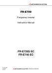
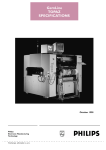
■ Derating Curve
Load rate (%)
Total output current
The temperature range within which the S8AS can be used is restricted by the maximum current that normally
flows for the total output. This restriction is given as a derating curve.
120
100
1
80
60
40
20
0
−20 −10
0
10
20
30
40
50
60
70
80
Ambient temperature (°C)
Note
1. The ambient temperature is measured at a point 50 mm below the S8AS.
2. Use forced cooling if necessary to satisfy the derating curve.
3. For 480-W models, reduce the load to 80% or less for long-term use at an input voltage of 95 VAC or less.
■ Abnormal Voltage Tripping
1.
The S8AS has an abnormal voltage tripping function. All branch outputs will be cut off if the input voltage
exceeds 28.8 VDC. This function, however, does not protect loads and internal parts from high voltages in
all cases. Be sure the output voltage is within the rated range.
2.
Outputs may be cut off by the abnormal voltage protection with loads that generate reverse peak electromotive force.
xiv
■ Abnormal Current Tripping
The S8AS has an abnormal current tripping function. A branch output will be cut off if its current exceeds a preset value. Also, all branch outputs will be cut off if their total peak output current exceeds a specified value.
Note
1. Continuing operation with overcurrent may occasionally result in deterioration or destruction of internal elements.
2. Do not use the S8AS for applications in which load inrush current or overload will frequently occur.
Doing so may result in deterioration or damage to internal components.
■ Maintenance Forecast Monitor Function
The accuracy of the maintenance forecast monitor function will be reduced in applications where the AC input
turns ON and OFF frequently.
■ Tripping Performance
There are three methods that can be used to determine abnormal current trippings: Standard Detection,
Instantaneous Detection, and Extended Detection. (This is not possible for the S8AS-24006N/48008N.)
Refer to 2-4-2 Over-current Protection Functions for details of cutoff performance.
Note
1. When the tripping alarm output operates, always remove the cause of the output first and then reset the
alarm.
2. When using a load with a fixed-power operation, the S8AS may cause a cutoff when the power supply is
turned OFF.
3. Tolerance of current tripping alarm threshold is ±0.3 A.
4. Use Extended Detection only when using OMRON Remote I/O Terminal with short-circuit detection.
■ Total Peak Output Current
The S8AS is designed to provide a temporary peak current to provide the overcurrent required to start load
devices.
The total peak output current for all branch outputs combined is given below.
If the total current exceeds any of these values, all branch outputs will be cut off according to the size of the
peak current or application time to ensure safety.
• 240-W Models
Input voltage range:
Peak current/Peak current pulse width:
200 to 240 VAC
17 A max. for 2 s max.
15 A max. for 5 s max.
13 A max. for 10 s max.
12 A max. for 20 s max.
If the total output peak current exceeds even one of these conditions, all branch outputs will be shut off to
ensure safety.
• 480-W Models
Input voltage range:
Peak current/Peak current pulse width:
200 to 240 VAC
27 A max. for 1 s max.
25 A max. for 2 s max.
22.5 A max. for 5 s max.
Note
1. If the input voltage range is not within the values specified above or the total output current exceeds the maximum peak current value, internal operation will become unstable and the branch outputs may be cut off.
2. Maintain the total current for normal operation after the load devices have started to within the rated ranges.
xv
3. Do not allow a peak current to flow again for at least 60 seconds after a peak current has exceeded the rated
current.
■ Startup Delay
The S8AS has a startup delay function that prevents cutoffs caused by inrush current at startup.
The startup delay disables the cutoff operation for 40 ms after the semiconductor relay turns ON.
To protect internal circuits, however, the relevant branch outputs will be cut off even during the startup delay
period if a current limit is exceeded within a specific time period.
Note The startup delay will not operate when a relay or other device is used for ON/OFF control on the output
side of the S8AS, so a cutoff operation may occasionally occur.
■ Dielectric Strength Test
The S8AS is designed to withstand 3,000 VAC for 1 minute between the AC input terminals collectively and
the branch output, I/O signal, or communications terminals collectively. When testing, set the cutoff current for
the withstand voltage test device to 20 mA.
Note
1. The S8AS may possibly be damaged from the impulse voltage if a testing device switch is used to abruptly
apply or cut off 3000 VAC. Increase the applied voltage gradually using the voltage adjustment on the testing
device.
2. When testing terminals together, always short the specified terminals so that the voltage is applied to all of
the terminals at the same time.
■ Insulation Resistance Test
When testing the insulation resistance, use a DC resistance meter at 500 VDC.
Note To prevent damage, always short branch output terminals (+/–), all I/O terminals, and communications
terminals before testing.
■ Output Voltage Adjustment
Default setting: Set as the rated voltage.
Adjustable range: Adjustable from –10% to +10% of the rated output voltage by using the V.ADJ. adjuster on
the front or the Power Supply. Turning the adjuster clockwise increases the output voltage, and turning it
counterclockwise decreases the output voltage.
Note
1. If the output voltage is set to less than 20 V (default setting), the undervoltage detection may be activated.
2. Do not exceed the rated output capacity and rated total output current after adjusting the output voltage.
3. The output voltage may increase beyond the allowable voltage range rated voltage +10% when the V.ADJ
adjuster is used. When adjusting the output voltage, check the output voltage of the power supply to make
sure that the load is not damaged.
■ No Output Voltage
The internal circuit’s overcurrent protection or overvoltage protection may operate. Alternatively, the latch
protection circuit may operate if there is a lightning surge or other large voltage applied to the input.
Contact your OMRON representative if there is still no output voltage after checking the following two points:
• Checking Overcurrent Protection
Check whether the load is in an overcurrent or short-circuited state. Remove the wires to the load before
checking.
• Checking Overvoltage Protection and Latching Protection
Turn the power supply OFF and leave it OFF for at least 3 minutes, then turn it ON again.
xvi
■ Startup Time
At startup, the S8AS will check hardware and software before starting the operation of branch outputs.
A time of approximately 3 seconds is required for these self-diagnostic functions.
Take this time into account when designing the system.
■ External Tripping Input
Wire the polarity of the external tripping input correctly. After completing wiring, confirm that operation is correct.
■ Tripping Alarm Output, Undervoltage Detection Output, Maintenance
Forecast Monitor Output, and Over-temperature Output
Photoswitch outputs: 30 VDC max., 50 mA max., residual voltage when ON: 2 V max., leakage current when
OFF: 0.1 mA max.
Wire all output signal circuits correctly. Internal current control circuits are not provided internally for output signals. Do not allow the output current to exceed 50 mA. After completing wiring, confirm that the circuits operate
correctly.
■ Displaying the Output Voltage
The voltage detection function displays on the 7-segment display the voltage that is monitored at the internal
circuit after AC/DC conversion. The displayed voltage will be somewhat lower than the value at the output
terminals of the power source due to internal voltage drop. To accurately confirm the output voltage, measure
it at the branch output terminal.
■ Prohibition of Parallel Connection
Do not connect branch outputs from the S8AS in parallel. Also, do not connect the branch outputs in parallel
with branch outputs of other S8AS Power Supplies.
S8AS
S8AS
S8AS
Connections cannot be made in parallel
with other branch output circuits.
■ Supplementary Information: Conformity to IEC and EN Safety Standards
Warning: The S8AS is a Class A product. In a residential, commercial, or light industrial environment, it may
cause radio interference. The S8AS is not intended to be installed in a residential environment. In a
commercial or light industrial environment with connection to a commercial power supply, the user may be
required to take adequate measures to reduce interference.
xvii
Using this Manual
■ Notation in this Manual
In this manual, the S8AS Smart Power Supply is referred to as the S8AS.
■ Notation of Setting Data
Setting data codes and contents are displayed in seven-segment display characters, as shown in the following
diagram.
V
xviii
SECTION 1
Features and Functions
This section describes the features and functions of the S8AS.
1-1
Overview of Features and Functions. . . . . . . . . . . . . . . . . . . . . . . . . . . . . . . .
2
1-2
S8AS Operating Modes . . . . . . . . . . . . . . . . . . . . . . . . . . . . . . . . . . . . . . . . .
7
1-3
Table of Basic Functions . . . . . . . . . . . . . . . . . . . . . . . . . . . . . . . . . . . . . . . . .
9
1-4
S8AS Operating Procedure . . . . . . . . . . . . . . . . . . . . . . . . . . . . . . . . . . . . . . .
13
1
Section 1-1
Overview of Features and Functions
1-1
Overview of Features and Functions
The S8AS Smart Power Supply is a 24-VDC power supply unit with an internal digital circuit protector that incorporates the highly reliable S8VS Switch
Mode Power Supply and the S8M Digital Multicircuit Protector in one unit.
The input power supply to the S8AS is 100 to 240 VAC at 50/60 Hz. Models
are available for 240 W with 6 branch outputs or for 480 W with 8 branch outputs, with and without communications. Models for which parameters cannot
be changed are also available.
The S8AS provides a stable 24-VDC power supply at an output current of 3.8
A maximum.
Model Number
Legend
S8AS Model Numbers
S8AS-@@@@@@
1
2 3
No.
Item
1
Output capacity
2
Number of output
branches
3
Communications /
Additional functions
Code
240
480
06
08
blank
N
R
Meaning
240 W
480 W
6 branch outputs
8 branch outputs
Changeable parameter settings with no communications
Unchangeable parameter settings with no
communications
Changeable parameter settings with communications (RS-485)
Reduced Space, Wiring, and Work
■ Combination of S8VS and S8M
The space required within the control panel and the amount of wiring have
been reduced by integrating a Digital Multicircuit Protector into a Switch Mode
Power Supply.
115 mm
170 mm for models with 4 branch outputs
245 mm for models with 8 branch outputs
2
Section 1-1
Overview of Features and Functions
■ S8AS-24006@ (240 W, 6 Branch Outputs)
115 mm
160 mm for models
with 6 branch outputs
■ S8AS-48008@ (480 W, 8 Branch Outputs)
115 mm
230 mm for models with 8 branch outputs
Power Supply and Branch Outputs
The power supply section incorporates the highly praised AC-DC conversion
circuit of the S8VS Switch Mode Power Supply in order to produce stable 24VDC power.
The branch output circuits consist of the protection circuits and tripping circuits of the S8M Digital Circuit Protector. They support various safety functions, such as overvoltage protection, overcurrent protection, and short-circuit
protection, as well as maintenance functions, such as monitoring using the
seven-segment display, error indications, and various alarm outputs.
Models that support communications can be monitored from a host computer
using RS-485 communications.
Branch Output Tripping Circuits
No-contact Switching
The S8AS built-in circuit protectors differ from conventional mechanical contact-type circuit protectors in that they use no-contact transistor relay switching. Without the contact life of mechanical circuit protectors, semiconductor
relays are able to provide a much longer lifetime. Digital processing also provides other benefits, such as being able to specify detailed overcurrent detection conditions.
Conventional contactstyle circuit protector
S8AS built-in circuit
protector
Overcurrent tripping
mechanism
Overcurrent
detection circuit
3
Overview of Features and Functions
Section 1-1
Tripping Current Can be
Set for Each Branch
Output
The abnormal tripping current value can be set for each branch output.
Abnormal Current
Detection and Tripping
Time
The abnormal current tripping characteristics can be set for each branch output. (This is not possible for the S8AS-24006N/48008N.)
Setting range: 0.5 to 3.8 A (in 0.1 A increments).
Tolerance of current tripping threshold: ±0.3 A.
There are three methods that can be used to determine abnormal current trippings. (This is not possible for the S8AS-24006N/48008N.)
■ Standard Detection
When the current exceeds the set value, the branch output is cut off within
100 ms.
■ Instantaneous Detection
When the current exceeds the set value, the branch output is cut off within
20 ms.
■ Extended Detection
When the current exceeds the set value, the branch output is cut off within
1,000 ms.
Error Indication and Alarm
Output for Abnormal
Current Tripping
The following will occur when an abnormal current is detected and the branch
output is cut off:
• The branch output status indicator will light red.
• The seven-segment display will show the error code A11 and the abnormal current value alternately.
• The external output terminal for tripping alarms (TRP) will turn ON. (The
photoswitch output will turn OFF.)
Always remove the cause of the abnormal current before resetting the alarm.
Tripping for Total Peak
Output Current
When the total branch output current exceeds the set value for a specified
amount of time, all branch outputs will be cut off.
• All branch output status indicators will light red.
• The seven-segment display will flash the error code A12.
• The external output terminal for tripping alarms (TRP) will turn ON. (The
photoswitch output will turn OFF.)
Abnormal Voltage
Tripping
If the output voltage exceeds 28.8 VDC, all branch outputs will be cut off in
order to protect load devices.
The following will happen when this occurs:
• The seven-segment display will show the error code A10 and the abnormal voltage alternately.
• The external output terminal for tripping alarms (TRP) will turn ON. (The
photoswitch output will turn OFF.)
Internal Temperature
Monitor
The S8AS has an built-in temperature sensor that constantly measures the
internal temperature. The temperature can be read from the seven-segment
display. The temperature display range is −20 to 100°C. The temperature sensor has one external output (TMP), which can be used to control cooling
equipment for the control panel.
The temperature output setting range is 25 to 90°C.
• The seven-segment display will show the error code A30 and temperature
(°C) alternately.
4
Section 1-1
Overview of Features and Functions
• The external output terminal for over-temperature (TMP) will turn ON.
(The photoswitch output will turn OFF.)
Maintenance Forecast
Monitor Function
This function calculates the condition of the electrolytic capacitor based on the
power-ON time and internal temperature of the Power Supply to forecast
when the Power Supply needs to be replaced. The monitor value can be set to
between 0.0 and 5.0 years (approximate) in increments of 0.5 years.
The following occurs when the estimated replacement time reaches the set
value:
• The seven-segment display will show the error code A23 and the replacement time (years) alternately.
• The external output terminal for the maintenance forecast monitor (LFE)
will turn ON. (The photoswitch output will turn OFF.)
Safety Functions
If an abnormal voltage or current is detected, the semiconductor relay will cut
off the branch output. In the unlikely event that the semiconductor relay cannot cut off an abnormal current or short-circuit current, the short-circuit protection fuse will cut the circuit to protect the system. If the branch output is cut off
by the fuse, an error indication will not be shown on the seven-segment display and the alarm output (TRP) will not operate.
The overcurrent protection fuse or over-temperature fuse cannot be replaced.
If a fuse burns out, use a different branch output or replace the S8AS.
External Outputs
The S8AS has 4 external outputs: the Tripping Alarm Output (TRP), Undervoltage Detection Output (LOW), Maintenance Forecast Monitor Output
(LFE), and Over-temperature Output (TMP).
Output
Tripping Alarm
Output (TRP)
Output condition
• Abnormal voltage tripping
If the output voltage exceeds
28.8 V, all branch outputs are
cut off.
• Abnormal current tripping
If a current exceeding the set
value is detected, the corresponding branch output is
cut off.
Test Mode only
When even one branch output
is disconnected.
Restoration condition
The output status is retained
when power is interrupted but
can reset with the reset operation.
Restore by connecting all
branch outputs, or by switching to any mode other than
Test Mode.
Undervoltage Detec- Output when the 24 VDC out- This output can be reset with
tion Output (LOW)
put falls below the undervolt- the reset operation. If the
age detection threshold.
alarm is cleared when the
power is turned ON, the output will be reset.
Over-temperature
Output when a temperature
The output is reset automatiOutput (TMP)
exceeding the threshold is
cally when the temperature
detected.
falls to 3°C below the overtemperature output threshold.
• Prepare to replace the
Maintenance Fore• Output when the estimated
cast Monitor Output
replacement time falls below Power Supply.
(LFE)
the set value.
• Take measures to lower the
internal temperature.
• Output when the replacement time can no longer be
calculated due to rise in temperature of the power supply
section.
5
Section 1-1
Overview of Features and Functions
Tripping Functions Using External Signals
Branch outputs can be forcibly cut off by turning ON the External Tripping
Input (TRG).
• Tripping using the External Tripping Input can be enabled or disabled
independently for each branch output. Refer to Tripping Input Trigger Setting: TRG (Trigger) on page 68.
• The External Tripping Input directly cuts off a branch output's DC circuit,
so it acts even faster than cutting off the output by turning OFF the normal
AC power supply.
• When a shutdown sequence has been set, this function can be used to
set a time lag for the branch output cutoff. (For details, refer to 2-6 Shutdown Sequence Function.)
• The tripping input type can be set. (Refer to 2-7 External Tripping Input
Function)
• EGE: Output cut off when the tripping input changes from OFF to ON.
• LVL: Output cut off when the tripping input changes from OFF to ON
and connected when tripping input changes from ON to OFF.
Additional Functions
Startup Sequence
Function
A delay can be set for the connection of the branch outputs. When you want to
apply a startup delay to the branch output, it is not necessary to construct an
external sequence circuit. The inrush current can be suppressed by applying
a delay and the Power Supply Unit's load can be reduced. (For details, refer to
2-5 Startup Sequence Function.)
Shutdown Sequence
Function
The branch outputs' cutoff can be delayed. When you want to apply a shutdown delay to the branch output, it is not necessary to construct an external
sequence circuit. (For details, refer to 2-6 Shutdown Sequence Function.)
Protecting Parameter
Settings (Protection Level
Settings)
The Protection Level can be set to restrict access to the parameters. Three
levels, levels 0, 1, and 2, are available. This function can be used to prevent
parameters from being changed or deleted inadvertently.
Protection level
Restrictions
0
There are no restrictions on reading and changing the parameter
settings.
1
Permits only reading and changing of the output voltage, current,
internal temperature, and maintenance forecast monitor parameters.
2
Permits only reading of the output voltage, current, internal temperature, and maintenance forecast monitor parameters.
The default setting is protection level 1. (For details, refer to 4-3 Changing the
Protection Level.)
Note
6
The read/write access for models that do not support parameter
changes (S8AS-24006N/48008N) cannot be changed regardless
of the protection level.
Section 1-2
S8AS Operating Modes
1-2
S8AS Operating Modes
The S8AS has 3 operating modes: Run Mode, Setting Mode, and Test Mode.
Run Mode
The output voltage, output current, internal temperature, and
run time are monitored while supplying 24 VDC to the branch
outputs. The monitored values can be displayed on the sevensegment display.
The S8AS automatically starts in Run Mode when the S8AS is
used for the first time.
This mode is used to set parameters. Branch output connections are the same as in Run Mode.
This mode is used to test operation. The factory default setting
for all outputs is ON, so any branch outputs that are not being
used must be turned OFF in Test Mode.
Setting Mode
Test Mode
(See note.)
Note
Changing the
Operating Mode
Test Mode can be entered only in protection level 0 or 1.
To change the operating mode, press the Up (SEL) (U) and Down (CH) (D)
Keys simultaneously for 3 s. The Mode Selection Menu will be displayed. Use
the Up (SEL) Key to select the desired operating mode and then press the
Enter ( ) Key.
Power ON
• When started for the
first time
• S8AS was not in Test
Mode when power
went OFF.
S8AS was in
Test Mode
when power
went OFF.
Mode Selection Menu
Run Mode
+
Press for 3 s.
Select Run Mode run (RUN)
(See
note 4.)
Select Setting Mode set (SET)
Setting Mode
+
Press for 3 s.
Select Test Mode tst (TST)
(See
note 4.)
Test Mode (See note 3.)
+
Press for 3 s.
Select Protection Level prt (PRT)
(See
note 4.)
Initialize Parameters ini (INI)
Note
The Initialize Parameters
command is displayed in
protection level 0 only.
(1) The Protection Level function can restrict parameter read/write access to
one of three levels. For details, refer to 4-3 Changing the Protection Level.
(2) The Initialize Parameters function restores all of the S8AS's parameter
settings to their default values. For details on default values, refer to 4-1
Parameter Table.
(3) Test Mode can be entered only in protection level 0 or 1.
(4) The Setting Mode, Protection Level, or Parameter Initialization options
cannot be accessed with models such as S8AS-24006N/48008N that do
not permit changes in parameter settings.
7
Section 1-2
S8AS Operating Modes
Turning the Power ON for
the First Time
• When a newly purchased S8AS is turned ON for the first time, it will enter
Run Mode with all the branch outputs turned ON. To change parameter
settings, return to the Mode Selection Menu and switch to Setting Mode.
Refer to SECTION 4 Parameter Settings for details on setting parameters.
• To start trial operation or to set branch output connections after setting the
parameters, return to the Mode Selection Menu and switch to Test Mode.
Refer to SECTION 5 Trial Operation to Actual Operation for details on the
operations in Test Mode.
• When changing to Run Mode after completing trial operation, return to the
Mode Selection Menu and switch to Run Mode. If the power is turned
OFF while the S8AS is in Test Mode, the S8AS will enter Test Mode again
the next time that the power is turned ON. All branch outputs will retain
the connection status they had before the power was turned OFF.
Normal Power-ON
Procedure
If the S8AS has been turned ON already, it will enter Run Mode or Test Mode
the next time that power is turned ON. If the S8AS was in Test Mode when the
power went OFF, it will start in Test Mode. If it was in a mode other than Test
Mode when the power went OFF, it will start in Run Mode.
In addition to selecting the operating mode, the Mode Selection Menu can be
used to select the protection level and initialize the parameters (see note 2).
(These options cannot be selected when using the S8AS-24006N/48008N.)
The Initialize Parameters function restores all of the S8AS's parameter settings to their default values. For details on default values, refer to Turning the
Power ON for the First Time.
Automatic Operation
after Power ON
When the rated voltage (100 to 240 VAC, 50/60 Hz) is applied to the AC input
terminal block, the S8AS performs self-diagnostics (hardware and software
checks) for approximately 3 seconds. (“AS” will flash on the seven-segment
display during the self-diagnostic process.) If no errors are detected, the
S8AS will immediately start connecting the branch outputs.
Branch outputs will not be connected if they were not set to ON in Test Mode.
Furthermore, if the startup sequence function (refer to 2-5 Startup Sequence
Function) has been set, the branch outputs will be connected according to
their corresponding settings.
Operation in Run
Mode
In Run Mode, the S8AS continuously measures the output voltage, branch
output circuit currents, and internal temperature, and compares these values
to the set values (both user-set parameters and system set values).
Monitor Operation
The monitored output voltage, branch output currents, branch output peak
current, total current, internal temperature, and replacement time can be read
on the S8AS's seven-segment display. The displayed value can be switched
with the Up (SEL) Key (U) and Down (CH) Key (D).
Tripping Operation
If the voltage or current is abnormal, the branch output will be cut off to protect
the circuit.
■ Abnormal Voltage Tripping
All branch outputs will be cut off if the output voltage exceeds 28.8 VDC in
order to protect the load devices.
■ Abnormal Current Tripping
A branch output will be cut off if the tripping current threshold (see note) or an
abnormal current is detected using the specified current detection method
(see note). (The tripping current threshold and current detection method cannot be changed for the S8AS-24006N/48008N.)
8
Section 1-3
Table of Basic Functions
An error code will be displayed, and the tripping alarm output will operate
when a branch output is cut off.
Other Status Monitoring
The internal temperature and replacement time status are monitored and
error processing is performed if an error is detected.
Operation in Setting
Mode
Setting Mode can be used to set the various parameters. The S8AS is in operating status when it is in Setting Mode. Branch outputs are connected in Setting Mode in the same way as in Run Mode. When an error is detected,
branch outputs will be cut off and alarms will be output, just as they are in Run
Mode.
Note
Operation in Test
Mode
If an error occurs in Setting Mode, the error code is not displayed.
In Test Mode, each branch output can be set to ON or OFF (connected or disconnected).
The factory default setting for all outputs is ON, so any branch outputs that are
not being used must be turned OFF in Test Mode.
In Test Mode, the operation of each branch circuit can be verified as well as
the operation of the startup sequence and shutdown sequence.
Note (a) If the power is turned OFF while the S8AS is in Test Mode, the
S8AS will enter Test Mode again the next time that the power is
turned ON.
(b) When an error occurs in Test Mode, branch outputs will be cut off
and external signals will be output, just as they are in Run Mode.
The error code will not be displayed.
(c) Refer to 7-3 Clearing Errors for details on clearing errors.
Note
(1) When the S8AS is shipped from the factory, all branch outputs are set to
ON (connected) and the S8AS will enter Run Mode when the power is
turned ON. After setting the parameters that require changing, switch to
Test Mode, set the switching status of the required branch outputs, and
then switch to Run Mode.
(2) If a branch output is OFF (disconnected) when the mode is changed from
Test Mode to Run Mode, it will not be connected (ON) in Run Mode.
(3) If the power is turned OFF while the S8AS is in Test Mode, the S8AS will
start in Test Mode the next time that the power is turned ON, but all
branch outputs will be OFF.
1-3
Table of Basic Functions
Monitor Functions
Monitored
parameter
Details
Sevensegment
display
Output voltage
Displays the output voltage.
Total current
Displays the sum of all the
branch output currents.
Branch output
current
Displays individual branch
output currents.
Indications
Branch
Unit
output
indicators
number
indicators
16.3 to
Not lit
30.0
0.0 to 40.0 All
branches
lit
0.0 to 20.0 Lit
V
A
A
9
Section 1-3
Table of Basic Functions
Monitored
parameter
Details
Sevensegment
display
Branch output
peak current
Replacement
time
Displays individual branch
output peak currents.
Displays the estimated number of years left until the
S8AS needs to be replaced.
(Setting: 0.0 to 5.0 years, in
0.5-year increments.)
Internal tempera- Displays the S8AS's interture
nal temperature.
Setting Functions
Indications
Branch
Unit
output
indicators
number
indicators
0.0 to 20.0 Lit
FUL, HLF
0.0 to 5.0
Not lit
−20 to 100 Not lit
°C
Refer to SECTION 4 Parameter Settings for details on parameter settings.
(These parameters cannot be changed for the S8AS-24006N/48008N.)
Data name
Detail
Undervoltage
The undervoltage detection output (LOW) is output
detection thresh- when the output voltage of the S8AS falls below this
old
detection threshold. The detection threshold can be
set in 0.1-V increments. Branch outputs will not be
cut off.
Abnormal current The current tripping threshold can be set for each
tripping threshold branch output in 0.1-A increments.
Abnormal current The tripping type can be set for each branch output.
tripping type
USU: Standard (tripping within 100 ms)
INS: Instantaneous (tripping within 20 ms)
LNG: Extended (tripping within 1,000 ms)
Set the expected number of years until the S8AS
Maintenance
forecast monitor needs to be replaced. When the estimated value falls
below the set value, the maintenance forecast monifunction
tor output (LFE) will turn ON. (The photoswitch output
will turn OFF.)
Over-temperaAn excessive temperature rise inside the S8AS will
ture threshold
be detected and the over-temperature output (TMP)
will turn ON. (The photoswitch output will turn OFF.)
This output can be used to control cooling equipment
to reduce the temperature in the control panel.
Startup
The connection of branch outputs may be initiated by
sequence
communications or when the power is turned ON,
and a time delay can be set for the connection
sequence. Connecting the branch outputs in
sequence instead of simultaneously can reduce the
inrush current and reduce the load on the Power Supply.
Shutdown
Branch outputs can be disconnected in sequence inisequence
tiated by communications or an external tripping input
(TRP), and a time delay can be set for the sequence.
Tripping trigger
The external tripping input function (TRG) can be
input
enabled (ON) or disabled (OFF) for each branch output.
Tripping trigger
The tripping trigger type can be set for all branches
type
that have the tripping input function enabled.
10
A
(flashing)
Yrs
Setting
range
18.0 to
26.4 V
0.5 to
3.8 A
USU/INS/
LNG
0.0 to
5.0 yr
25 to 90°C
0.0 to
99.9 s
0.0 to
99.9 s
OFF, ON
EGE, LVL
Section 1-3
Table of Basic Functions
Data name
Protection level
Reset operation
Tripping/
Alarm Functions
Detail
Setting
range
0 to 2
The Protection Level function can restrict parameter
read/write access by setting one of three levels. The
default protection level is level 1.
The tripping alarm output and alarm output can be
KEY, ALL
cleared after removing the cause of the alarm by the
following two methods.
• KEY: RST Key only.
• ALL: RST Key or turning power OFF and ON again.
There are three ways for the S8AS's tripping function to operate:
• Tripping by user-set parameters
• Tripping by the S8AS's system monitor
• Tripping by external operation
The external signal outputs include the Tripping Alarm Output (TRP), Undervoltage Detection Output (LOW), Maintenance Forecast Monitor Output
(LFE), and Over-temperature Output (TMP).
Tripping Functions
Setting
Parameter
settings
Abnormal volt- Output cut off for voltage over 28.8 VDC. None
age tripping
Short-circuit
Output cut off at 16 A for 20 ms max.
None
current
Output cut off at 11 A for 60 ms max.
tripping
Abnormal total Output cut off when the sum of all branch None
output currents exceeds the set value for
current tripping
a specific length of time.
Abnormal
0.5 to 3.8 A (in 0.1-A increments)
current
Select from standard, instantaneous, and extended
tripping
detection methods.
(See note 1.)
External trip• External input signal (TRG) ON
ping input
• Tripping by communications.
Note
Operating range
Outputs
cut off
All branch
outputs
Individual
branch output
All branch
outputs
Individual
branch output
Specified
output
(See note
2.)
(1) The tripping function operates within 100 ms when the S8AS is set to
standard detection, within 20 ms when it is set to instantaneous detection, and within 1,000 ms when it is set to extended detection.
(2) The TRG signal applies only to the branch outputs for which the external
tripping input is enabled. For details, refer to 2-7 External Tripping Input
Function.
11
Section 1-3
Table of Basic Functions
Alarm Output and Error
Display Functions
Symbol
TRP
LOW
LFE
TMP
Note
Output
Operation
name
Tripping
Abnormal Voltage Tripping Operation
alarm output When the output voltage exceeds 28.8 VDC,
all branch outputs are cut off and the TRP
output is turned ON. (The photoswitch output
is turned OFF.)
Abnormal Current Tripping Operation
When the branch output current exceeds the
set value, the branch output is cut off and the
TRP output is turned ON. (The photoswitch
output is turned OFF.)
Volt-amperage (VA) Tripping Operation
When the voltage times the current (VA)
exceeds the set value for a specified amount
of time, the branch output is cut off and the
TRP output is turned ON. (The photoswitch
output is turned OFF.)
Abnormal Total Current Tripping Operation
When the total output current exceeds the set
value, all branch outputs are cut off and the
TRP output is turned ON. (The photoswitch
output is turned OFF.)
Indicates that there are branch outputs that
are not connected. This error is not output in
any mode other than Test Mode.
When there is a disconnected branch output
in Test Mode, the TRP output is turned ON.
(The photoswitch output is turned OFF.)
UndervoltSetting range: 18.0 to 26.4 VDC (0.1-V increage detecments)
tion output
When the output voltage falls below the set
value, the LOW output is turned ON. (The
photoswitch output is turned OFF.)
MainteSetting range: 0.0 to 5.0 years (0.5-yr increnance fore- ments) (See note 1.)
cast monitor When the internally calculated replacement
output
time falls below the set value, the LFE output
is turned ON. (The photoswitch output is
turned OFF.)
Overheating LFE output is turned ON (the photoswitch outalarm (See put is turned OFF) when the replacement
time cannot be calculated correctly due to rise
note 2.)
in internal temperature.
Setting range: 25 to 90°C (1°C increments)
Over-temperature
When the temperature falls below the set
output
value minus 3°C, the TMP output and the
error code shown on the seven-segment display will be automatically cleared.
Error code
displayed
A10
A11/Current
(alternating)
A11/Current
(alternating)
A12
---
A21/Voltage
(alternating)
A23/
Replacement time
(alternating)
A23/HOT
(alternating)
A30/Temperature (alternating)
(1) In this manual, the lifetime of the Unit is expressed in years.
(2) If the overheating alarm stays on for more than 3 hours, it can no longer
be cleared.
12
Section 1-4
S8AS Operating Procedure
1-4
S8AS Operating Procedure
Using the S8AS
Typical Startup Procedure
Using the S8AS's Keys
Preparation
Installation and wiring
See Section 3 Installation and Wiring.
Power ON
Set parameters
Trial run in Test Mode
Verify operation
See Section 4 Initial Settings.
(S8AS-24006N/48008N parameters
cannot be changed.)
See Section 5 Trial Run.
Branch outputs that will not be used can be
set to OFF (disconnected.)
Verify proper operation while monitoring status in Run Mode.
Actual operation
Summary of Application Objectives and Settings
Desired objective/
Settings
usage
Use as a circuit
In Setting Mode, set the abnormal current tripbreaker with overcur- ping threshold (C-V) for the branch output being
rent tripping.
used and set the abnormal current tripping
detection setting (C-T) to standard detection
(USU).
In Setting Mode, set the abnormal current tripUse as a circuit
breaker for short-cir- ping threshold (C-V) for the branch output being
cuit current protecused and set the abnormal current tripping
tion.
detection setting (C-T) to instantaneous detection (INS).
Detect a drop in
In Setting Mode, set the undervoltage detection
power supply voltthreshold (V-U). Take the alarm signal from the
age.
Undervoltage Detection Output (LOW) terminal.
When an undervoltage is detected, the sevensegment display will show error code A21 and
the LOW output photoswitch output will go OFF.
Apply a separate
time lag when connecting each branch
output.
In Setting Mode, set the startup sequence
(UPS).
Apply a separate
In Setting Mode, set the shutdown sequence
time lag when cutting (DWS) and enable the External Tripping Input
off each branch out- (TRG).
put.
Details
p. 30,
p. 62
p. 29,
p. 50
p. 63
p. 37,
p. 66
p. 38,
p. 67
Use the S8AS
The seven-segment display and the LFE termi- p. 34,
replacement time for nal signal output can be used to check the esti- p. 64
better maintenance. mated replacement time using the maintenance
forecast monitor function.
13
Section 1-4
S8AS Operating Procedure
Desired objective/
usage
Monitor temperature
rise in control panel
and prevent overheating.
Restrict read/write
access of parameters to prevent mistaken operations.
14
Settings
Details
In Setting Mode, set the over-temperature output p. 35,
threshold (TMP). Take the signal from the Over- p. 65
temperature Output (TMP) terminal and use that
p. 50
signal to operate a fan or air conditioner.
Select the protection level setting (PRT) from the p. 54,
Mode Selection Menu and set the desired prop. 59
tection level.
SECTION 2
Specifications and Functions
This section provides the specifications of the S8AS and describes special S8AS functions.
2-1
Component Names and Functions . . . . . . . . . . . . . . . . . . . . . . . . . . . . . . . . .
16
2-2
Internal Configuration. . . . . . . . . . . . . . . . . . . . . . . . . . . . . . . . . . . . . . . . . . .
20
2-3
Specifications . . . . . . . . . . . . . . . . . . . . . . . . . . . . . . . . . . . . . . . . . . . . . . . . .
22
2-4
Basic Function Details . . . . . . . . . . . . . . . . . . . . . . . . . . . . . . . . . . . . . . . . . .
29
2-4-1
Voltage Monitoring and Protection Functions . . . . . . . . . . . . . . . . .
29
2-4-2
Over-current Protection Functions . . . . . . . . . . . . . . . . . . . . . . . . . .
30
2-4-3
Maintenance Forecast Monitor Function . . . . . . . . . . . . . . . . . . . . .
34
2-4-4
Over-temperature Output . . . . . . . . . . . . . . . . . . . . . . . . . . . . . . . . .
35
2-5
Startup Sequence Function . . . . . . . . . . . . . . . . . . . . . . . . . . . . . . . . . . . . . . .
37
2-6
Shutdown Sequence Function . . . . . . . . . . . . . . . . . . . . . . . . . . . . . . . . . . . . .
38
2-7
External Tripping Input Function . . . . . . . . . . . . . . . . . . . . . . . . . . . . . . . . . .
39
15
Section 2-1
Component Names and Functions
2-1
Component Names and Functions
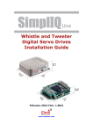
Component Names
■ 240-W Output Models
1. AC input terminals
13. Communications terminals
9. Branch output indicators
2. Protective earth (PE) terminal
8. Seven-segment display
10. Unit indicators
11. Status indicators
12. Operation keys
6. Output indicator (DC ON)
3. Branch output terminals (+)
7. Output voltage adjuster (V.ADJ)
4. Branch output terminals (−)
5. I/O signal terminals
■ 480-W Output Models
1. AC input terminals
9. Branch output indicators
2. Protective earth (PE) terminal
13. Communications terminals
8. Seven-segment display
10. Unit indicators
11. Status indicators
12. Operation keys
6. Output indicator (DC ON)
3. Branch output terminals (+)
7. Output voltage adjuster (V.ADJ)
4. Branch output terminals (−)
5. I/O signal terminals
(1) AC Input Terminals (L and N) and (2) Protective Earth (PE) Terminal
Connect the input power supply (100 to 240 VAC, 50/60 Hz) (commercial
power) to the Power Supply.
Do not connect an inverter output as the power supply.
Make sure that the protective earth (PE) terminal is connected to ground to
prevent electric shock or malfunction.
(The terminal screws are M4.)
L
N
100 to 240 VAC,
50/60 Hz
(3) Positive (+) and (4) Negative (−) Branch Output Terminals
Connect to each branch output. Positive and negative branch outputs are connected to separate terminal blocks with two positive and two negative terminals for each branch output.
16
Section 2-1
Component Names and Functions
• 240-W Model Output Terminals
Branch
output 1
+
Branch
output 2
+
Branch
output 3
+
Branch Branch
output 4 output 5
+
+
Branch
output 6
+
Branch output
common (−)
Branch
output 1
−
Branch
output 2
−
Branch
output 3
−
Branch Branch
output 4 output 5
−
−
Branch
output 6
−
• 480-W Model Output Terminals
Branch
output 1
+
Branch
output 3
+
Branch
output 2
+
Branch Branch
output 4 output 5
+
+
Branch Branch Branch
output 6 output 7 output 8
+
+
+
Branch output
common (−)
Branch
output 1
−
Branch
output 2
−
Branch
output 3
−
Branch Branch
output 4 output 5
−
−
Branch Branch
output 6 output 7
−
−
Branch
output 8
−
(5) I/O Signal Terminals
TRP
LOW
LFE
TMP
TRG (−)
TRG (+)
COM
TMP
LFE
LOW
TRP
Connect the external outputs and external tripping inputs.
Tripping Alarm Output
Turns ON to indicate when an abnormal voltage
or current was detected and the output was cut
off (The photoswitch output will turn OFF.).
Undervoltage DetecTurns ON when the 24-VDC output voltage
tion Output
from the S8AS falls below the threshold.
(The photoswitch output will turn OFF.).
Maintenance Forecast Turns ON to indicate when the number of years
Monitor Output
to the set replacement time has been reached
(The photoswitch output will turn OFF.).
Over-temperature
Turns ON to indicate that the temperature
Output
exceeded the over-temperature output threshold (The photoswitch output will turn OFF.).
17
Section 2-1
Component Names and Functions
COM
Common Terminal
Common terminal shared by the four alarm outputs above.
External Tripping Input Can be used to send an input signal from an
external device to cut off a branch output.
TRG (+)
TRG (−)
(6) Output Indicator (DC ON)
The indicator is lit green when the S8AS is in normal operation. It indicates
that the 24 VDC output can be used as a supply voltage.
DC ON
(7) Output Voltage Adjuster (V.ADJ)
The output voltage is set at a default of the 24-VDC rated voltage.
Use the output voltage adjuster to adjust the output voltage.
The adjustable range is −10% to +10 % of the rated output voltage. Turning the adjuster clockwise increases the output voltage, and turning it
counterclockwise decreases the output voltage.
V. ADJ
Note
(1) If the output voltage is set to less than 20.0 V (default setting), the undervoltage detection may be activated.
(2) Do not exceed the rated output capacity and rated total output current after adjusting the output voltage.
(3) The output voltage may increase beyond the allowable voltage range (rated voltage +10%) when the V.ADJ adjuster is used. When adjusting the
output voltage, check the output voltage of the power supply to make sure
that the load is not damaged.
(4) Do not use excessive force to turn the adjuster (V.ADJ). It may be damaged.
(8) Seven-segment Display (Red)
Displays measured values or set values on a 3-digit LED display.
8. 8. 8.
(9) Branch Output Indicators (Orange)
(10) Unit Indicators (Orange)
Shows the branch output number and the unit for the value shown in the
seven-segment display.
• Six-branch Output Model
1
2
3
4
5
6
Branch output number indicators
1 to 6: 240 W
1 to 8: 480 W
V
A
Yrs
18
V
A Y r s °C
s
Unit indicators
Lit or flashing when the display is related to the corresponding
branch output.
Lit when displaying the output voltage.
Lit when displaying the output current.
Flashes when displaying the peak output current.
Lit when the number of years to the set replacement time is
displayed.
Section 2-1
Component Names and Functions
°C
s
Lit when displaying the temperature.
Lit when setting the startup sequence time or shutdown
sequence time.
(11) Status indicators (Green/Red)
Indicate the connection and cut off status for the branch outputs.
• Six-branch Output Model
1
2
3
4
5
6
Not lit
Green
Lit
Flash
Red
Lit
Flash
Not
connected
Connected
Not connected
Cut off
Cut off
Set to OFF (disconnected) or forcibly
cut off by command.
Connected normally.
In the startup sequence and waiting for
connection.
Cut off due to an error.
Cut off by an internal error.
(12) Operation Keys
Reset (RST) Key
Used to clear the error status when a branch output was cut
off by an error or there was an alarm output.
RST
Enter (ENT) Key
Used to switch the display item, enter or execute settings, etc.
Up (SEL) Key
Used to change the display item forward or to increase a set
value.
Down (CH) Key
Used to switch the branch output or to decrease a set value.
The branch output number that is set remains the same in
other modes.
(13) Communications Terminals (A (−), B (+)) (Only for Models That
Support Communications)
Used to connect to the RS-485 communications line.
A (−) B (+)
19
Section 2-2
Internal Configuration
2-2
Internal Configuration
S8AS-24006 (Model with NO Communications and Changeable Parameter Settings)
S8AS-24006N (Model with NO Communications and Unchangeable Parameter Settings)
S8AS-24006R (Model with Communications and Changeable Parameter Settings)
(S8AS-24006R only)
RS-485
A (−)
B (+)
Communications
circuit
TRP
Voltage
detection
Temperature
detection
Switches
LOW
Display
circuit
LFE
Processing circuit
(main processing)
TMP
COM
Communications between
processing circuits (RS-232C)
TRG+
TRG−
Branch output 6
Branch output 5
Branch output 4
Rectification
and smoothing
AC (L)
INPUT
AC (N)
Fuse:
12 A
Processing
circuit
(replacement
time)
Harmonic
current
control
SCREW (M3.5)
Cutoff
circuit
Currentlimiting
circuit
Currentdetection
resistor
Cutoff circuit
Thermal
fuse
Noise
filter
Rectifi- Inrush
cation current
limit
Smoothing
Rectification
and smoothing
Drive control
circuit
Power supply
detection
Voltage-ON
detection
Photocoupler
20
Branch output 3
Branch output 2
Branch output 1
Currentdetection
resistor
Current
fuse
+V
DC OUTPUT
−V
−V
SCREW (M4)
Section 2-2
Internal Configuration
S8AS-48008 (Model with NO Communications and Changeable Parameter Settings)
S8AS-48008N (Model with NO Communications and Unchangeable Parameter Settings)
S8AS-48008R (Model with Communications and Changeable Parameter Settings)
(S8AS-48008R only)
Communications
circuit
RS-485
A (−)
B (+)
TRP
Voltage Temperature Switches
detection detection
LOW
Display
circuit
LFE
Processing circuit
(main processing)
TMP
Communications between
processing circuits (RS-232C)
Branch output 8
Branch output 7
Branch output 6
Branch output 5
Branch output 4
Branch output 3
Branch output 2
AC (L)
INPUT
AC (N)
Branch output 1
Harmonic
current
control
SCREW (M3.5)
Currentlimiting
circuit
Cutoff circuit
CurrentCutoff detection
circuit resistor
Fuse: Noise
12 A filter
Inrush Rectificurrent cation
limit
COM
TRG+
TRG−
Smoothing
Thermal
fuse
Rectification
and smoothing
Currentdetection
resistor
Current
fuse
+V
+V
−V
DC OUTPUT
SCREW (M4)
Voltage-ON
detection
Control
circuits
Drive
circuit
Processing
circuit
Voltage
detection
Current
detection
Current-ON
detection
Auxiliary power
supply circuit
Rectification and
smoothing
• The S8AS compares the measured input voltage, current, and internal
temperature with the preset parameters. These values can be read on the
S8AS's seven-segment display.
• When an error is detected, the branch output will be cut off or an alarm
will be output. The error code and PV will be displayed alternately on the
seven-segment display.
• When an abnormal voltage or current is detected, the semiconductor
relay will cut off the branch output. In the unlikely event that the semiconductor relay cannot cut off an abnormal current or short-circuit current, the
redundant protection circuit, and the short-circuit protection fuse (12.0 A
minimum) will operate to protect the system.
• The S8AS has a built-in temperature sensor, which can detect a temperature rise inside the S8AS. When the internal temperature exceeds the
detection threshold, the Over-temperature Output (TMP) photoswitch output will turn OFF.
• When an internal circuit has failed, the components can generate excessive heat. As a safety precaution against this kind of failure, the S8AS is
equipped with a function that cuts off operation using a thermal fuse.
Models that support communications have a RS-485 port, and can be connected to a host computer.
21
Section 2-3
Specifications
2-3
Specifications
Ratings and Characteristics
S8AS-24006@
Item
Model
Efficiency (Typ.)
Input
Voltage range (See note 1.)
condi- Frequency (See note 1.)
tions
Current
100-V input
200-V input
Power factor
Harmonic current
Leakage cur- 100-V input
rent
200-V input
Inrush current 100-V input
(See note 2.) 200-V input
Output Number of branches
condi- Maximum cutoff output current
tions
(per branch)
Functions
Total output current
Allowable voltage range (See
note 3.)
Ripple noise voltage
Output leakage current
Input fluctuation
Load fluctuation (rated input
voltage)
Temperature fluctuation
Startup time (See note 2.)
Output hold time (See note 2.)
Tripping func- Abnormal volttions
age tripping
Abnormal current tripping
(See note 2.)
Abnormal total
current tripping
Tripping Alarm
Output
Undervoltage
Undervoltdetection
age detection functions
Undervoltage
detection output
Maintenance Maintenance
forecast mon- forecast moniitor function
tor
Maintenance
forecast monitor output
22
S8AS-24006
S8AS-24006N
80% min.
100 to 240 VAC (85 to 264 VAC)
50/60 Hz (47 to 63 Hz)
3.8 A max.
2.0 A max.
0.95 min.
EN61000-3-2
0.5 mA max.
1.0 mA max.
25 A max. (for a cold start at 25°C)
50 A max. (for a cold start at 25°C)
6
3.8 A
S8AS-24006R
10 A
±10 A (with V.ADJ)
2.0%[P-P] max. (for rated input and output voltage) (See note 4.)
10 mA max.
0.5 % max. (Input: 85 to 264 VAC, 100 % load) (See note 5.)
4.0 % max. (rated input, 0% to 100% load) (See note 5.)
0.05%/°C max.
3,000 ms max. (for rated input and output voltage) (See note 4.)
20 ms min. (for rated input and output voltage) (See note 4.)
28.8 V (Cannot be changed.)
Setting range: 0.5 to
3.8 A (Cannot be
Setting range: 0.5 to
3.8 A (in 0.1-A increchanged.)
3.8 A (in 0.1-A increments)
ments)
Branch outputs are cut off when the total output current is more than 17 A for
2 s, 15 A for 5 s, 13 A for 10 s, or 12 A for 20 s.
Photoswitch output
30 VDC max. and 50 mA max., Leakage current: 0.1 mA max., Residual voltage: 2 V max.
20.0 V (Cannot be
Setting range: 18.0 to
Setting range: 18.0 to
changed.)
26.4 V (in 0.1-V incre26.4 V (in 0.1-V increments)
ments)
Photoswitch output
30 VDC max. and 50 mA max., Leakage current: 0.1 mA max.,
Residual voltage: 2 V max.
Setting range: 0.0 to
0.5 yr (Cannot be
Setting range: 0.0 to
5.0 yr (in 0.5-yr increchanged.)
5.0 yr (in 0.5-yr increments)
ments)
Photoswitch output
30 VDC max. and 50 mA max., Leakage current: 0.1 mA max.,
Residual voltage: 2 V max.
Section 2-3
Specifications
Item
Functions
Model
Over-temper- Over-temperaature detecture
tion function Over-temperature output
Display functions
Output voltage
display
Output current
display
Maintenance
forecast monitor display
Temperature
display
External Tripping Input
Startup sequence
Shutdown sequence
Communications
Sampling period
Parallel connection
Series connection
S8AS-24006
S8AS-24006N
S8AS-24006R
Setting range: 25 to 90°C 90°C (Cannot be
Setting range: 25 to 90°C
(in 1°C increments)
changed.)
(in 1°C increments)
Photoswitch output
30 VDC max. and 50 mA max., Leakage current: 0.1 mA max.,
Residual voltage: 2 V max.
Display range: 17.0 to 30.0 V
Display accuracy: 2% rdg ±1 digit max.
Branch output display range: 0.0 to 4.0 A
Peak output current display range: 0.0 to 20.0 A
Total current display range: 0.0 to 40.0 A
Display accuracy: 5% FS (4 A) ±1 digit max.
Display range: FUL (Full)/HLF (Half)/0.0 to 5.0 yr
Display range: −20 to 100°C
Display accuracy: 2°C ±1 digit max.
The input can be enabled All branch outputs:
or disabled for each
Enabled (Cannot be
changed.)
branch output.
19.2 to 30 VDC, mini19.2 to 30 VDC, minimum signal width: 10 ms, mum signal width: 10 ms,
tripping after input within tripping after input within
20 ms + the shutdown
20 ms + the shutdown
sequence set time
sequence set time
Branch output 1: 0.0 s
Setting range: 0.0 to
(Cannot be changed.)
99.9 s in 0.1-s increments
Branch output 2: 0.4 s
(Cannot be changed.)
Branch output 3: 0.8 s
(Cannot be changed.)
Branch output 4: 1.2 s
(Cannot be changed.)
Branch output 5: 1.6 s
(Cannot be changed.)
Branch output 6: 2.0 s
(Cannot be changed.)
Setting range: 0.0 to
All branch outputs:
99.9 s in 0.1-s incre0.0 s (Cannot be
ments
changed.)
Not supported
1 ms
Not supported.
Not supported.
The input can be enabled
or disabled for each
branch output.
19.2 to 30 VDC, minimum signal width: 10 ms,
tripping after input within
20 ms + the shutdown
sequence set time
Setting range: 0.0 to
99.9 s in 0.1-s increments
Setting range: 0.0 to
99.9 s in 0.1-s increments
Supported (RS-485)
23
Section 2-3
Specifications
Item
Others
Model
Ambient operating temperature
Storage temperature
Ambient operating humidity
Withstand voltage
Insulation resistance
Vibration resistance
Shock resistance
Output indicator
Conducted EMI
Radiated EMI
Safety standards
Weight
Note
S8AS-24006
S8AS-24006N
S8AS-24006R
Refer to the derating curve (no icing or condensation). (See note 2.)
−25 5o 65°C
25% to 85% (storage: 25% to 90%)
3.0 kVAC for 1 min between all input terminals collectively and all branch output, all I/O signal, and all communications terminals collectively (Detection current: 20 mA)
2.0 kVAC for 1 min between all inputs and protective earth (Detection current:
20 mA)
1.0 kVAC for 1 min between protective earth and all branch output, all I/O signal, and all communications terminals collectively (Detection current: 20 mA)
500 VAC for 1 min between all branch output and all I/O signal/communications
terminals collectively (Detection current: 20 mA)
500 VAC for 1 min between all I/O signal terminals collectively and communications terminals collectively (Detection current: 20 mA)
500 VAC for 1 min between all I/O signal terminals collectively and all output
signal terminals collectively (detection current: 20 mA)
100 MΩ min. at 500 VDC between the protective earth terminal or all input terminals collectively and all branch output, all I/O signal, and all communications
terminals collectively
No abnormality after 10 to 55 Hz at 0.375-mm single amplitude for 2 h each in 3
directions.
No abnormality after 150 m/s2 3 times each in 6 directions.
Provided (Color: green)
Conforms to EN 61204-3 Class A and FCC Class A.
Conforms to EN 61204-3 Class A.
cULus: UL508 (Listing. Class2: Per UL1310), CSA C22.2 No.107.1 (Class2: Per
CSA C22.2 No.223)
cURus: UL60950-1, CSA C22.2 No.60950-1
EN: EN50178, EN60950-1
VDE: VDE0160, VDE0805 Teil1
1,600 g max.
(1) Do not use an inverter output for the Power Supply. Inverters with an output frequency of 50/60 Hz are available, but the rise in the internal temperature of the Power Supply may result in ignition or burning.
(2) Refer to Derating Curve on page xiv for details.
(3) If the output voltage adjuster (V. ADJ) is turned, the voltage will increase
by more than 10% of the voltage adjustment range. When adjusting the
output voltage, confirm the actual output voltage from the Power Supply
and be sure that the load is not damaged. If the output voltage exceeds
28.8 V, all branch outputs will be cut off.
(4) Rated input and output conditions: Rated input voltage, rated frequency,
rated output voltage, rated total output current, and maximum cutoff output current.
(5) 100% load conditions: Rated output voltage, rated total output current,
and maximum cutoff output current.
24
Section 2-3
Specifications
S8AS-48008@
Item
Model
Efficiency (Typ.)
Input
Voltage range (See note 1.)
condi- Frequency (See note 1.)
tions
Current
100-V input
200-V input
Power factor
Harmonic current
Leakage cur100-V input
rent
200-V input
Inrush current 100-V input
(See note 2.)
200-V input
Output Number of branches
condi- Maximum cutoff output curtions
rent (per branch)
Total output current
Allowable voltage range (See
note 3.)
Ripple noise voltage
Output leakage current
Input fluctuation
Load fluctuation (rated input
voltage)
Temperature fluctuation
Startup time (See note 2.)
Output hold time (See note
2.)
Func- Tripping func- Abnormal
tions
tions
voltage tripping
Abnormal
current tripping
(See note
2.)
Total abnormal current
tripping
S8AS-48008
S8AS-48008N
80% min.
100 to 240 VAC (85 to 264 VAC)
50/60 Hz (47 to 63 Hz)
7.4 A max.
3.9 A max.
0.95 min.
EN61000-3-2
0.5 mA max.
1.0 mA max.
25 A max. (for a cold start at 25°C)
50 A max. (for a cold start at 25°C)
8
S8AS-48008R
3.8 A
20 A
±10 A (with V.ADJ)
2.0%[P-P] max. (for rated input and output voltage) (See note 4.)
10 mA max.
0.5 % max. (Input: 85 to 264 VAC, 100 % load) (See note 5.)
4.0 % max. (rated input, 0% to 100% load) (See note 5.)
0.05%/°C max.
3,000 ms max. (for rated input and output voltage) (See note 4.)
20 ms max. (for rated input and output voltage) (See note 4.)
28.8 V (Cannot be changed.)
Setting range: 0.5 to
3.8 A (in 0.1-A increments)
3.8 A (Cannot be
changed.)
Setting range: 0.5 to
3.8 A (in 0.1-A increments)
Branch outputs are cut off when the total output current is more than 27 A for 1 s,
25 A for 2 s, or 22.5 A for 5 s.
Tripping
Alarm
Output
Photoswitch output
30 VDC max. and 50 mA max., Leakage current: 0.1 mA max.,
Residual voltage: 2 V max.
20.0 V (Cannot be
Setting range: 18.0 to
Setting range: 18.0 to
Undervoltage Undervoltchanged.)
26.4 V (in 0.1-V incredetection func- age detec- 26.4 V (in 0.1-V increments)
ments)
tion
tions
UndervoltPhotoswitch output
age detec- 30 VDC max. and 50 mA max., Leakage current: 0.1 mA max.,
tion output
Residual voltage: 2 V max.
Maintenance
MainteSetting range: 0.0 to
0.5 yr (Cannot be
Setting range: 0.0 to
forecast moni- nance fore- 5.0 yr (in 0.5-yr increchanged.)
5.0 yr (in 0.5-yr incretor function
cast monitor ments)
ments)
MaintePhotoswitch output
nance fore- 30 VDC max. and 50 mA max., Leakage current: 0.1 mA max.,
cast monitor Residual voltage: 2 V max.
output
25
Section 2-3
Specifications
Item
Functions
Model
Over-tempera- Over-temture detection perature
function
threshold
Over-temperature
output
Display functions
Output voltage
display
Output current display
S8AS-48008
S8AS-48008N
Setting range: 25 to 90°C 90°C (Cannot be
(in 1°C increments)
changed.)
Photoswitch output
30 VDC max. and 50 mA max., Leakage current: 0.1 mA max.,
Residual voltage: 2 V max.
Display range: 17.0 to 30.0 V
Display accuracy: 2% rdg ±1 digit max.
Branch output display range: 0.0 to 4.0 A
Peak output current display range: 0.0 to 20.0 A
Total current display range: 0.0 to 40.0 A
Display accuracy: 5% FS (4 A) ±1 digit max.
Display range: FUL (Full)/HLF (Half)/0.0 to 5.0 yr
Maintenance forecast monitor
display
TemperaDisplay range: −20 to 100°C
ture display Display accuracy: 2°C ±1 digit max.
External Tripping Input
The input can be enabled All branch outputs:
Enabled (Cannot be
or disabled for each
branch output.
changed.)
19.2 to 30 VDC, minimum 19.2 to 30 VDC, minimum
signal width: 10 ms,
signal width: 10 ms,
tripping after input within tripping after input within
20 ms + the shutdown
20 ms + the shutdown
sequence set time
sequence set time
Startup sequence
Setting range: 0.0 to
Branch output 1: 0.0 s
99.9 s in 0.1-s increments (Cannot be changed.)
Branch output 2: 0.4 s
(Cannot be changed.)
Branch output 3: 0.8 s
(Cannot be changed.)
Branch output 4: 1.2 s
(Cannot be changed.)
Branch output 5: 1.6 s
(Cannot be changed.)
Branch output 6: 2.0 s
(Cannot be changed.)
Branch output 7: 2.4 s
(Cannot be changed.)
Branch output 8: 2.8 s
(Cannot be changed.)
Shutdown sequence
Setting range: 0.0 to
All branch outputs:
99.9 s in 0.1-s increments 0.0 s (Cannot be
changed.)
Communications
Not supported
Sampling period
1 ms
Parallel connection
Not supported.
Series connection
Not supported.
26
S8AS-48008R
Setting range: 25 to 90°C
(in 1°C increments)
The input can be enabled
or disabled for each
branch output.
19.2 to 30 VDC, minimum
signal width: 10 ms,
tripping after input within
20 ms + the shutdown
sequence set time
Setting range: 0.0 to
99.9 s in 0.1-s increments
Setting range: 0.0 to
99.9 s in 0.1-s increments
Supported (RS-485)
Section 2-3
Specifications
Item
Model
Others Ambient operating temperature
Storage temperature
Ambient operating humidity
Withstand voltage
Insulation resistance
Vibration resistance
Shock resistance
Output indicator
Conducted EMI
Radiated EMI
Safety standards
Weight
Note
S8AS-48008
S8AS-48008N
S8AS-48008R
Refer to the derating curve (no icing or condensation). (See note 2.)
−25 5o 65°C
25% to 85% (storage: 25% to 90%)
3.0 kVAC for 1 min between all input terminals collectively and all branch output,
all I/O signal, and all communications terminals collectively (detection current:
20 mA)
2.0 kVAC for 1 min between all inputs and protective earth (Detection current:
20 mA)
1.0 kVAC for 1 min between protective earth and all branch output, all I/O signal,
and all communications terminals collectively (Detection current: 30 mA)
500 VAC for 1 min between all branch output and all I/O signal/communications
terminals collectively (Detection current: 20 mA)
500 VAC for 1 min between all I/O signal terminals collectively and communications terminals collectively (Detection current: 20 mA)
500 VAC for 1 min between all I/O signal terminals collectively and all output signal terminals collectively (detection current: 20 mA)
100 MΩ min. at 500 VDC between the protective earth terminal or all input terminals collectively and all branch output, all I/O signal, and all communications terminals collectively
No abnormality after 10 to 55 Hz at 0.375-mm single amplitude for 2 h each in 3
directions.
No abnormality after 150 m/s2 3 times each in 6 directions.
Provided (Color: green)
Conforms to EN 61204-3 Class A and FCC Class A.
Conforms to EN 61204-3 Class A.
cULus: UL508 (Listing. Class2: Per UL1310), CSA C22.2 No.107.1 (Class2: Per
CSA C22.2 No.223)
cURus: UL60950-1, CSA C22.2 No.60950-1
EN: EN50178, EN60950-1
VDE: VDE0160, VDE0805 Teil1
2,400 g max.
(1) Do not use an inverter output for the Power Supply. Inverters with an output frequency of 50/60 Hz are available, but the rise in the internal temperature of the Power Supply may result in ignition or burning.
(2) Refer to Derating Curve on page xiv for details.
(3) If the output voltage adjuster (V. ADJ) is turned, the voltage will increase
by more than 10% of the voltage adjustment range. When adjusting the
output voltage, confirm the actual output voltage from the Power Supply
and be sure that the load is not damaged. If the output voltage exceeds
28.8 V, all branch outputs will be cut off.
(4) Rated input and output conditions: Rated input voltage, rated frequency,
rated output voltage, rated total output current, and maximum cutoff output current.
(5) 100% load conditions: Rated output voltage, rated total output current,
and maximum cutoff output current.
27
Section 2-3
Specifications
External Output and External Tripping Input Specifications
The S8AS has 4 external outputs: the Tripping Alarm Output (TRP), Undervoltage Detection Output (LOW), Maintenance Forecast Monitor Output
(LFE), and Over-temperature Output (TMP). It also has an External Tripping
Input (TRG).
TRP
Tripping Alarm
Output circuit
Undervoltage
Detection Output
circuit
LOW
Maintenance
Forecast Monitor
Output circuit
LFE
TMP
Over-temperature
Output circuit
Output common
TRG+
External Tripping
Input circuit
TRG−
I/O Circuit Configuration
Name
Circuit configuration
Tripping Alarm Output (TRP), Output circuit
Undervoltage Detection OutFrom internal power supply circuit
put (LOW), Maintenance Forecast Monitor Output (LFE) and
Over-temperature Output
(TMP)
Note A photo relay with a
photo MOS-FET and
infrared diode coupling
is used.
I/O specifications
30 VDC and 50 mA
max.
TRP
LOW
LFE
TMP
Signal from CPU
COM
External Tripping Input (TRG)
Input circuit
TRG (+)
19.2 to 30.0 VDC
Minimum signal width:
10 ms
TRG (−)
Note
28
When a branch output is cut off with the External Tripping Input, it cuts off
power to the branch output even faster than turning OFF the S8AS's power
supply.
Section 2-4
Basic Function Details
2-4
Basic Function Details
2-4-1
Voltage Monitoring and Protection Functions
Abnormal Voltage
Tripping
When the output voltage converted from AC to DC exceeds 28.8 V, all of the
branch outputs will be cut off simultaneously and a TRP alarm will be output.
The seven-segment display will show error code A10.
It is not necessary for the user to set any parameters for this function.
Tripping
Seven-segment display
operation
28.8 VDC min. Alternately displays error
code A10 and the voltage.
20 ms max.
Outputs
Conditions
required to reset
The Tripping Alarm Voltage below
Output (TRP) pho- 28.5 V and after
toswitch output
tripping (15 s has
turns OFF.
elapsed after previous reset.)
28.8 V
28.5 V
24-VDC output voltage
20 ms
max.
Branch output
TRP output
Reset possible
Undervoltage
Detection
An undervoltage detection threshold can be set between 18.0 and 26.4 V.
Setting
range
Default
value
18.0 to
20.0 V
26.4 VDC
Operation
Operation
Seven segment
display
Alternately
When the
displays error
voltage is
lower than the code A21 and
the voltage.
detection
threshold continuously for
80 ms or
more, the
alarm is output within
100 ms.
Outputs
Conditions
required to
reset
Voltage above
The Underthe detection
voltage
threshold
Detection
Output (LOW) +0.3 V continuously for at
photoswitch
least 500 ms.
turns OFF.
• If the output voltage falls below the detection threshold, the seven-segment display will show the error code A21 and the voltage value, and the
Undervoltage Detection Output (LOW) will turn OFF within 100 ms.
• The error display and Alarm Output can be reset when the voltage has
been above the detection threshold +0.3 V for 500 ms longer.
29
Section 2-4
Basic Function Details
Power
supply
voltage
(V-U) +0.3 V
V-U: Undervoltage
detection threshold
500 ms
100 ms
Undervoltage detection output (LOW)
Reset possible
Undervoltage
detection threshold
Power supply
voltage
Branch output
current
Branch output
voltage
Connected
Not connected
Connected
Undervoltage
alarm output (LOW)
Reset signal
2-4-2
Over-current Protection Functions
Abnormal Current
Tripping Function
When an abnormal current is detected, the S8AS cuts off the branch outputs
via semiconductor relays.
Each branch output's tripping current can be set between 0.5 and 3.8 A (in
0.1-A increments).
One of the following three detection methods can be selected for each branch
in order to detect abnormal currents (except for the S8AS-24006N/48008N,
which always use the same detection method.)
• Standard detection (tripping within 100 ms)
• Instantaneous detection (tripping within 20 ms)
• Extended time detection (tripping within 1,000 ms)
30
Section 2-4
Basic Function Details
Setting
range
0.5 to 3.8 A
Default
value
3.8 A
Tripping
type
Standard
Instantaneous
Extended
time
Operation
Error code
and alarm
output
The error
When a current higher than codeA11
the set value is and current
are disdetected, the
played alterbranch output
is cut off within nately on the
seven-seg100 ms.
ment disWhen a current higher than play and the
the set value is Tripping
Alarm Outdetected, the
put (TRP)
branch output
is cut off within photoswitch
output turns
20 ms.
OFF.
When a current higher than
the set value is
detected, the
branch output
is cut off within
1,000 ms.
Conditions
required to
reset
After tripping
(15 s has
elapsed
after the previous reset.)
When the abnormal current is detected and branch output is cut off, the error
code (A11) and present current are displayed alternately on the seven-segment display and the Tripping Alarm Output (TRP) is turned OFF.
The status indicator of the branch output that was cut off will flash red.
To clear the error, eliminate the cause of the error, and then press the Reset
Key. Once an error has been reset, another reset operation cannot be performed for at least 15 seconds.
Abnormal current
tripping threshold
Current
Standard detection: 100 ms max.
Instantaneous detection: 20 ms max.
Extended detection 1,000 ms max
Tripping Alarm
Output (TRP)
Reset possible
31
Section 2-4
Basic Function Details
Current Tripping Characteristics
■
Standard Detection
Time (ms)
Setting
range
Currentlimiting
by internal
circuits
Tripping region
Tolerance of current tripping alarm threshold:
±0.3 A. When the tripping current (0.5 to
3.8 A) is detected, it is
cut off within 100 ms.
100
60
20
0.5
■
3.8
11
16
19
Current (A)
Instantaneous Detection
Time (ms)
Setting
range
Tripping region
Currentlimiting
by internal
circuits
Tolerance of current tripping alarm threshold:
±0.3 A. When the tripping current (0.5 to
3.8 A) is detected, it is
cut off within 20 ms.
20
0.5
■
19
3.8
Current (A)
Extended Detection
Time (ms)
Setting
range
Tripping region
Currentlimiting
by internal
circuits
1,000
Tolerance of current tripping alarm threshold:
±0.3 A.When the tripping current (0.5 to
3.8 A) is detected, it is
cut off within 1,000 ms.
60
20
0.5
Note
Note
32
3.8
11
16
19
Current (A)
The S8AS contains a current-restricting circuit that prevents a current above a specific value from flowing. The current is thus restricted during the time required to cut off the output.
After sampling and converting each branch output's current every 1 ms, the
S8AS processes the values in the CPU and controls the branch output cutoffs. This method achieves high-speed, high-accuracy tripping. In addition, to
minimize the effects of excessive currents caused by short-circuits, the S8AS
is equipped with built-in current-limiting circuits. Consequently, there is a
Section 2-4
Basic Function Details
region in which the current is limited, as shown in the current tripping characteristics graphs.
Current actually flowing
Current value
Converted digital value
1 ms sampling period
Example sampling chart
Time
Abnormal Total Current Tripping Function
The S8AS monitors the total output current as well as the branch output currents. When the total output current exceeds the set value, all branch outputs
will be cut off. There are a number of conditions for the tripping current and
time. If even one of these conditions is detected, the abnormal total current
tripping function will be activated. The following table outlines the tripping conditions. (Input voltage range: 200 to 240 VAC)
Power-ON Total current (A)
time (s)
240W
480W
1 s min.
2 s min.
5 s min.
10 s min.
20 s min.
--17 A
15 A
13 A
12 A
27 A
25 A
22.5 A
−
−
Operation
Error code and
alarm output
Conditions
required to
reset
The error code After tripping
When the total
current reaches A12 will flash on (15 s has
these values, all the seven-seg- elapsed after
the previous
branches will be ment display
reset.)
cut off within 20 and the Tripping Alarm Outms.
put (TRP)
photoswitch output will turn
OFF.
−: Not applicable
Note
(1) If the input voltage range is not within the values specified above or the
total output current exceeds the maximum peak current value, internal
operation will become unstable and the branch outputs may be cut off.
(2) Maintain the total current for normal operation after the load devices have
started to within the rated ranges.
(3) Do not allow a peak current to flow again for at least 60 seconds after a
peak current has exceeded the rated current.
33
Section 2-4
Basic Function Details
Startup Delay
Normally, a large inrush current may run through the system when equipment
starts. Tripping operation can be disabled for a short time after the semiconductor relay goes ON in order to prevent this inrush current from being
detected as an abnormal current and cutting off operation. This temporary
disabling of the tripping function is called the startup delay.
Power supply
voltage
Branch output
voltage
No cutoff during startup delay even if set value is exceeded.
Abnormal current tripping threshold
Branch output
current
Startup delay (40 ms)
100 ms max. (standard detection)
ON (closed)
Tripping Alarm
Output (TRP)
OFF (open)
OFF (open)
Note
The startup delay disables the tripping operation for the specified
period of time. The inrush current during this time can be displayed
as the peak output current. The S8AS, however, contains a currentrestricting circuit, so the peak value is not necessarily an accurate
measure of the peak inrush current of the connected device.
Safety Functions
Short-circuit Protection
Fuse
If an error occurs that prevents the semiconductor relay from cutting off a
branch output, the short-circuit protection fuse will blow to protect the circuit.
Note
Thermal Fuse
If an error occurs that prevents the semiconductor relay from cutting off a
branch output and the temperature of the S8AS's internal resistors rises
abnormally high, the S8AS's thermal fuse will blow to prevent a fire hazard.
Note
2-4-3
If the fuse blows, that branch output cannot be used.
If the fuse blows, that branch circuit cannot be used.
Maintenance Forecast Monitor Function
The maintenance forecast monitor function calculates the replacement time
from the power-ON time and internal temperature. The maintenance forecast
monitor output (LFE) will operate when the calculated value reaches the set
value. (The set value is fixed at 0.5 years for the S8AS-24006N/48008N and
cannot be changed.) When the maintenance forecast monitor output (LFE) is
turned ON, the error code A23 and the estimated replacement time are displayed alternately on the seven-segment display.
Initial capacity
ful
Capacity at replacement time
hlf
4.5
(L-0.5)
1.5
1.0
0.5
0.0
5.0
Electrolytic
capacitor capacity
34
Seven-segment display
Maintenance forecast
monitor output
LFE output when L = 1.0
2.0 1.5 1.0 0.5
0
Section 2-4
Basic Function Details
When the life of the electrolytic capacitor (expected value = 10 yr) has halved,
the remaining life span (5 yr) is divided into 10 levels (in 0.5-yr increments).
These levels are used by the maintenance forecast monitor output (LFE) to
display the number of years that are left before the Power Supply needs to be
replaced.
Note
2-4-4
The expected life span of the S8AS is 10 years, but it will change
depending on the amount of time it is in operation and the ambient
temperature.
Over-temperature Output
When the temperature exceeds the set value continuously for more than 1 s,
the seven-segment display will show error code A30 and the Over-temperature Output (TMP) will go OFF.
The error display and Over-temperature Output are reset automatically when
the temperature has been below the set value minus 3°C for more than 5 s.
Setting
range
25 to 90°C
Over-temperature Output
(TMP)
Default
value
90°C
Operation
The output is
turned OFF
when the temperature higher
than the set
value continuously for more
than 1 s.
Sevensegment
display
Alternately
displays
error code
A30 and the
temperature(°C).
Outputs
Conditions
required to
reset
Reset autoThe Overtemperature matically
when the
Output
(TMP) pho- temperature
toswitch out- falls below
the set value
put turns
minus 3°C.
OFF.
When the temperature falls below the set value minus 3°C, the over-temperature output automatically turns ON.
• The over-temperature output (TMP) can be used to start an exhaust fan
or air conditioner to reduce the temperature in the control panel.
• The initial value is set at 90°C so that the over-temperature output is
essentially disabled at the beginning.
t: Over-temperature output threshold
(t-3)°C
Temperature °C
1s
5s
Error display and
Over-temperature
Output (TMP)
Example Application
Automatic reset
The output is normally closed (ON) and goes OFF when there is an error, so
receive the TMP output through an auxiliary relay. In addition, the output will
go ON momentarily when the power is turned ON, so receive the output
through a time-delay relay. (For details, refer to page 50.)
35
Section 2-4
Basic Function Details
S8AS
TMP
TR
X
COM
TR
IM
Fan, etc.
24 VDC
Relationship between
Control Panel
Temperature and S8AS
Internal Temperature
The internal temperature of the S8AS is displayed. This is not necessarily the
same as the ambient temperature of the S8AS or the temperature inside the
control panel. The difference between the internal temperature of the S8AS
and the ambient temperature depends on the current flowing through the
S8AS. Consider this difference in the application.
The following graph provides reference information on the displayed internal
temperature and the ambient temperature.
Conditions: The same current was output from all branch outputs in a constant-temperature bath held at a constant temperature
36
Section 2-5
Startup Sequence Function
■
240 W
0.5 A per branch (total output current: 3 A)
Displayed temperature (°C)
1.67 A per branch (total output current: 10 A)
100
80
60
40
20
0
−20
−20 −10
0
10
20
30
40
50
60
70
Ambient temperature (°C)
■
480 W
0.5 A per branch (total output current: 4 A)
Displayed temperature (°C)
2.5 A per branch (total output current: 20 A)
100
80
60
40
20
0
−20
−20 −10
0
10
20
30
40
50
60
70
Ambient temperature (°C)
2-5
Startup Sequence Function
The inrush current may cause a voltage drop if all of the branch outputs are
connected simultaneously and there is little spare capacity in the power supply or the loads connected to the branch outputs are capacitive loads. A significant voltage drop may cause an output to be cut off. In this case, a time delay
can be applied between the connections of the branch outputs to minimize the
voltage drop.
Note
(1) The time delay can be set between 0.0 and 99.9 s. (If the delay is set to
0.0 s, the startup sequence will not operate and the branch output will be
connected immediately.)
(2) The startup sequence is designed for the four branch outputs on one
S8AS. It does not provide time synchronization between outputs on more
than one S8AS.
After the power supply is turned ON and the self-diagnostics are performed,
the S8AS will start connecting the branch output according to their preset
startup sequence times.
37
Section 2-6
Shutdown Sequence Function
Power supply
voltage
Branch output 1
voltage
Setting time
Branch output 2
voltage
Setting time
Branch output 3
voltage
Setting time
Branch output n voltage
(n: maximum branch
output number)
Setting time
Self-diagnostics (0.5 s min.)
• The branch output's status indicator will flash green during the startup
sequence time until it is connected.
• The startup sequence's operation can be verified in Test Mode. For
details, refer to 5-3 Checking Sequence Operation.
• The startup sequence for models with unchangeable settings
(S8AS-24006N/48008N) cannot be changed.
Branch output
number
Setting time
Note
1
0.0 s
2
0.4 s
3
0.8 s
4
1.2 s
5
1.6 s
6
2.0 s
7
2.4 s
8
2.8 s
The startup sequence functions in the following processes:
• Connecting when power is turned ON
• Reconnecting during a reset operation
• Simultaneous connection of all outputs in Test Mode
2-6
Shutdown Sequence Function
When the S8AS's input power supply is turned OFF, all of the branch outputs
are turned OFF (disconnected) simultaneously. On the other hand, when the
branch outputs are cut off by the external tripping input or communications, a
time delay can be applied between the branch output disconnections.
Note
(1) The time delay can be set between 0.0 and 99.9 s. (If the delay is set to
0.0 s, the startup sequence will not operate and the branch output will be
cut off immediately.)
(2) The shutdown sequence is designed for the four branch outputs on one
S8AS. It does not provide time synchronization between outputs on more
than one S8AS.
38
Section 2-7
External Tripping Input Function
External tripping input
Branch output 1 voltage
Setting time
Branch output 2 voltage
Setting time
Branch output 3 voltage
Setting time
Branch output n voltage
(n: maximum branch
output number)
Setting time
Within 20 ms
(3) When operation is cut off due to an abnormal voltage (above 28.8 V), all
of the branch outputs will be cut off simultaneously.
(4) The shutdown sequence function will operate on a branch output only if
the external tripping input is enabled for that branch output. For details,
refer to Tripping Input Trigger Setting: TRG (Trigger) on page 68.
(5) The shutdown sequence setting times for all branch outputs for the S8AS24006N/48008N are set to 0.0 s and cannot be changed.
• The shutdown sequence's operation can be verified in Test Mode. For
details, refer to 5-3 Checking Sequence Operation.
Note
The shutdown sequence functions in the following processes:
• Cutoff processing for the external tripping input
• Simultaneous cutoff of all outputs in Test Mode
2-7
External Tripping Input Function
The external tripping input (TRG) can be used to cut off or reconnect branch
outputs using an external input signal. The following settings are required to
use this function.
Item
External tripping
input activation
Tripping trigger type
Function
Enables the external tripping
input (TRG) function for each
branch.
Sets the external tripping
input trigger signal type.
Settings
ON (enabled)
OFF (disabled)
EGE (edge trigger)
LVL (level trigger)
The external tripping input is enabled and tripping type for the S8AS-24006N/
48008N is set to EGE and these settings cannot be changed.
39
Section 2-7
External Tripping Input Function
Tripping Trigger Type: Edge Trigger (EGE)
10 ms
Trigger signal
Branch output A voltage
(tripping input enabled)
Branch output B voltage
(tripping input disabled)
500 ms
a
Reset *
a: 20 ms + Shutdown sequence setting time
*: Connected after startup sequence setting time has elapsed.
If the trigger signal (TRG) stays OFF for more than 10 ms and the branch output is disconnected for more than 500 ms, the reset input can be received.
Tripping Trigger Type: Level Trigger (LVL)
Trigger signal
Branch output A voltage
(tripping input enabled)
Branch output B voltage
(tripping input disabled)
a
a: 20 ms + Shutdown sequence setting time
b: 20 ms + Startup sequence setting time
40
b
SECTION 3
Installation and Wiring
This section describes how to install and wire the S8AS.
3-1
Installing the S8AS . . . . . . . . . . . . . . . . . . . . . . . . . . . . . . . . . . . . . . . . . . . . .
42
3-2
Installation. . . . . . . . . . . . . . . . . . . . . . . . . . . . . . . . . . . . . . . . . . . . . . . . . . . .
44
3-3
Power Supply and Input/Output Wiring . . . . . . . . . . . . . . . . . . . . . . . . . . . . .
47
3-4
RS-485 Port Wiring. . . . . . . . . . . . . . . . . . . . . . . . . . . . . . . . . . . . . . . . . . . . .
52
41
Section 3-1
Installing the S8AS
3-1
Installing the S8AS
Installation and
Wiring Precautions
To increase the S8AS system's reliability and take full advantage of the
S8AS's functions, observe the following precautions when installing the S8AS.
Installation Site
Avoid locations with any of the following conditions when installing the S8AS.
• Locations subject to a temperature below −10°C or over 60°C
• Locations subject to a humidity below 25% or over 85% (no condensation/
icing)
• Locations subject to direct sunlight
• Locations subject to exposure to liquids, debris, or corrosive gases
• Locations subject to severe shock or vibration
• Locations near equipment that generates strong high-frequency noise or
surges
Always enclose or protect the S8AS sufficiently in the following locations.
• Locations subject to static electricity or other forms of noise.
• Locations subject to strong electromagnetic fields.
• Locations subject to possible exposure to radioactivity.
• Locations close to power lines.
Installation in
Cabinets or Control
Panels
When the S8AS is being installed in a cabinet or control panel, always provide
suitable ambient conditions as well as access for operation and maintenance.
Ambient Temperature
The operating temperature range for the S8AS is −10°C to 60°C. Observe the
following precautions.
• Provide enough space for good air flow.
• Do not install the S8AS above equipment that generates a large amount
of heat, such as heaters, transformers, or high-capacity resistors.
• If the ambient temperature in the cabinet may exceed 60°C, install an
exhaust fan or air conditioner and use the Over-temperature Output to
operate the cooling equipment.
Control
panel
Fan
S8AS
Vent
• Mount the S8AS at least 20 mm away from heat sources.
• Leave at least 75 mm between the S8AS and other devices above and
below it.
42
Section 3-1
Installing the S8AS
Other control devices
Air flow
75 mm min.
20 mm min.
75 mm min.
Other control devices
43
Section 3-2
Installation
3-2
Installation
When mounting the S8AS in a panel, use DIN Rail. Surface installation cannot
be used.
Mounting in a Panel
• The S8AS must be installed in the orientation shown below to ensure
adequate cooling.
• Do not install the S8AS in any of the following orientations.
Incorrect
Incorrect
44
Incorrect
Incorrect
Section 3-2
Installation
External Dimensions
S8AS-24006@ (240-W
Model with 6 Branch
Outputs)
142.4
124.7
160
10
122
Three, M3.5 square washers
S8AS-24006
POWER SUPPLY
A(-)
B(+)
RS485
L
N
1
34.9
2
3
4
5
6
115
+V
Class2
OUTPUT
DC 24V 3.8A
DC ON
-V
-V
+1
+2
+3
+4
+5
+6
-1
-2
-3
-4
-5
-6
V.ADJ
TRP LOW LFE TMP COM + TRG -
131.8
S8AS-48008@ (480-W
Model with 8 Branch
Outputs)
V A Yrs ˚C s
1 2 3 4 5 6
INPUT
50/60Hz AC100-240V 3.8A
M4 square washers
(sliding: 15 max.) 4.5
5.08
142.4
124.7
122
10
230
Three, M3.5 square washers
S8AS-48008
POWER SUPPLY
L
A(-)
N
B(+)
RS485
INPUT
1 2 3 4 5 6 7 8
V A Yrs ˚C s
50/60Hz AC100-480V 3.8A
1
34.9
Class2
OUTPUT
DC 24V 3.8A
DC ON
3
4
5
6
7
8
115
+V
-V
-V
+1
+2
+3
+4
+5
+6
+7
+8
-1
-2
-3
-4
-5
-6
-7
-8
V.ADJ
TRP LOW LFE TMP COM + TRG -
131.9
2
5.08
M4 square washers
(sliding: 15 max.)
4.5
Attachment to the DIN
Rail
The S8AS attaches to the DIN Rail with one snap. Hang the S8AS on the top
of the DIN Rail with the installation notch on the back of the S8AS, pivot the
S8AS downward, and press until the S8AS locks securely on the Rail.
1,2,3...
1. Pull out the two lock levers on the S8AS.
Lower the S8AS so that the installation notch hooks onto the top of the DIN
Rail.
2. Hook the installation notch on the top of the DIN Rail.
1. Pull out the lock levers.
45
Section 3-2
Installation
2. Press the S8AS onto the DIN Rail and push in the lock levers.
Press the lock levers until the locks engage securely.
3. Press the S8AS firmly onto the DIN Rail
4. Press in the lock levers until the locks engage securely.
After the S8AS is mounted on the DIN Rail, attach an End Plate on each
side of the Power Supply to secure it in place.
■
Recommended End Plate
10
PFP-M
6.2
M4 × 8
Pan-head
screw
50
1.8
1
35.5 35.3
1.8
11.5
10
1.3
4.8
M4 spring
washer
Removal
When removing the S8AS from the DIN Rail, pull the lock lever down with a
flat-blade screwdriver and pivot the S8AS upward to remove it.
CH
46
SEL
ENT
Section 3-3
Power Supply and Input/Output Wiring
3-3
Power Supply and Input/Output Wiring
Wiring Precautions
• When wiring, cover the top of the S8AS to prevent wire strands from
entering. After completing the wiring, be sure to remove the cover to avoid
overheating.
• Use the following crimp terminals on the power input wires and tighten the
terminal screws to the specified torque.
8 mm max.
8 mm max.
AC input terminals and protective earth (PE) terminals: M3.5
Negative branch output terminals: M4
Selecting the Wire
Terminals
Name
Recommended Wire type
wire diameter
AWG14 to
Screw ter- AC input terminals
minals
and protective earth AWG16 (Crosssection area:
(PE) terminal
1.309 to
2.081 mm2)
Branch output termi- AWG12 to
nals (−), UL StanAWG14 (Crossdard
section area:
2.081 to
3.309 mm2)
Branch output termi- AWG12 to
nals (−), CSA Stan- AWG20 (Crossdard
section area:
0.517 to
3.309 mm2)
Positive branch out- AWG12 to
Screwless termi- put terminals, nega- AWG24 (Crosssection area:
tive branch output
nals
terminals, I/O signal 0.2 to 2.5 mm2)
terminals, and communications terminals
Torque
Wire
stripping
length
Solid or
stranded
1.08 N·m
(9.6 in lb)
8 to
10 mm
Solid or
stranded
1.2 N·m
8 to
(10.6 in lb) 10 mm
Solid or
stranded
1.0 N·m
(8.8 in lb)
8 to
10 mm
Solid or
stranded
---
10 mm
Refer to the following table when selecting wire to use for the power supply.
AWG
30
28
26
24
22
20
18
16
14
12
10
Cross-sec- Configuration
tional area
(wires/mm)
(mm2)
0.051
0.081
0.129
0.205
0.326
0.517
0.823
1.309
2.081
3.309
5.262
7/0.102
7/0.127
7/0.16
11/0.16
17/0.16
26/0.16
43/0.16
54/0.18
41/0.26
65/0.26
104/0.26
Voltage
Max. recommended current (A)
drop per A
UL1007
UL1015
(mV/m)
(300 V 80°C)
(600 V 105°C)
358
0.12
--222
0.15
0.2
140
0.35
0.5
88.9
0.7
1.0
57.5
1.4
2.0
37.6
2.8
4.0
22.8
4.2
6.0
14.9
5.6
8.0
9.5
--12.0
6.0
--22.0
3.8
--35.0
47
Section 3-3
Power Supply and Input/Output Wiring
Maximum Recommended Current:
The values listed in the table above are for bundles of up to 4 wires. If 5 or
more wires are bundled together, reduce the max. current to 80% of the listed
current.
The following chart shows only the relationship between the voltage drop per
meter and the current and wire length. Be sure that the current actually being
used does not exceed the max. recommended current.
Voltage drop (mV)
Voltage Drop per Meter
(UL1015 Heat-resistant
PVC Wire)
The current
shown is the allowed current.
In actual applications, use a
current below
the maximum
recommended
current.
Current (A)
Wiring the AC Input
and Protective Earth
(PE) Terminals
• Use 100 to 240 VAC (85 to 264 VAC) 50/60 Hz power supply with minimal
voltage fluctuation. Use wires with a high current carrying capacities.
• Be sure to connect the protective earth (PE) terminal to ground to prevent
electric shock and malfunction.
100 to 200 VAC 50/60 Hz
(commercial power supply)
M3.5
L
N
Power supply terminal block
Wiring the Branch
Outputs
48
Two positive and two negative terminals are used for each branch output.
Section 3-3
Power Supply and Input/Output Wiring
■
Wiring the Branch Output Connector
240 W
Branch
output 1
+
Branch
output 2
+
Branch
output 3
+
Branch
output 4
+
Branch
output 5
+
Branch
output 6
+
+
Branch
output 1
−
+
Branch
output 2
−
Branch
output 3
−
Branch
output 4
−
Branch
output 5
−
Branch
output 6
−
Branch
circuit 6
−
Branch
circuit 1
Branch output common (−)
−
480 W
Branch
output 1
+
Branch
output 2
+
Branch
output 3
+
Branch
output 4
+
Branch
output 5
+
Branch Branch
output 6 output 7
+
+
Branch
output 1
−
Branch
output 2
−
Branch
output 3
−
Branch
output 4
−
Branch
output 5
−
Branch
output 6
−
Branch
output 8
+
+
+
Branch
output 7
−
Branch
output 8
−
Branch
circuit 8
Branch
circuit 1
−
Branch output common (−)
−
Branch output
common (−)
Note
Wiring the Terminal Block
Connectors
You may connect the positive terminals or the negative terminals of the same
branch output in parallel, but do not connect them with other branch outputs.
Use a solid or stranded wire. If you are using stranded wire, twist the end
before connecting it to make a clean connection.
Release Button
10 mm
• Strip the wire for approximately 10 mm from the end.
• Insert a flat-blade screwdriver into the release button to release the lock.
Insert the wire into the round hole, and then release the button to lock the
wire in place.
49
Section 3-3
Power Supply and Input/Output Wiring
• When inserting the wire, make sure that the stripped portion of the wire is
fully inserted and not left exposed.
• After completing a connection, lightly pull on the wire to make sure that it
has been locked in properly.
Wiring the External
Outputs and External
Tripping Input
The TRP, LOW, LFE, and TMP outputs operate as normally closed outputs,
which are OFF when the power is OFF, ON during normal operation, and OFF
when an error has occurred. If you want to use these an external output as a
normally open output, invert the signal through an auxiliary relay (X). When
doing so, the alarm may turn ON momentarily when the power supply is
turned ON. To prevent this, delay the signal through the delay relay (TR).
The branch output is cut off when the External Tripping Input (TRG) is ON
(connected).
TR
X1
X2
X3
No.
2
3
4
5
6
7
50
Negative Tripping
Input (−)
X4
Delay Relay
1
COM TRG(+) TRG(−)
Positive Tripping
Input (+)
Maintenance
Forecast Monitor
Output
TMP
Output Common
LFE
Over-temperature
Output
LOW
Undervoltage
Detection Output
Tripping Alarm
Output
TRP
TR
X1 X2
X3
X4
Tripping Input
Function
The photoswitch output turns OFF when the
branch output is cut off due to an abnormal
voltage or abnormal current.
LOW
Undervoltage
The photoswitch output turns OFF when the
Detection Output output voltage drops below the set value.
The photoswitch output turns OFF when the
LFE
Maintenance
Forecast Monitor estimated replacement time drops below the
set value.
Output
TMP
Over-temperature The photoswitch output turns OFF when the
Output
S8AS's internal temperature exceeds the
over-temperature output threshold.
COM
Output Common
Common terminal for the four outputs
described above.
TRG (+) External Tripping Branch outputs can be cut off from an external operation. (The shutdown sequence is
TRG (−) Input
applied in this case.)
TRP
Name
Tripping Alarm
Output
Section 3-3
Power Supply and Input/Output Wiring
■
Internal Circuits
Output
circuits
Input
circuit
30 VDC, 50 mA max.,
photoswitch output
19.2 to 30.0 VDC
Minimum signal width: 10 ms
Tripping Alarm
Output circuit
Undervoltage
Detection
Output circuit
TRP
LOW
Maintenance
Forecast Monitor
Output circuit
LFE
Over-temperature Output circuit
TMP
External
Tripping Input
circuit
TRG+
Output
common
TRG−
51
Section 3-4
RS-485 Port Wiring
3-4
RS-485 Port Wiring
Wiring the RS-485
Port
S8AS models with communications have an RS-485 port that can be connected with a host computer or controller.
10 mm
• Strip 10 mm from the ends of the RS485 cable's wires.
Press the Release
Button all of the
way in and insert
the wire.
A (−) B (+)
• Press the terminal's release button all
the way in and insert the wire into the
round wire hole. When the wire is
inserted, be sure that the wire conductor is not exposed.
• Release the release button to lock the
wire in place.
• After wiring, verify that the wires are
securely locked in the terminals.
Example Connection to a Host Computer
• The connection format is 1:1 or 1:N. Up to 32 nodes can be connected to
a host computer.
• Insert a Cramp Filter (E04SR301334 manufactured by SEIWA) in the
cable as a countermeasure against noise.
RS-232C
interface
Computer
Name
Pin
Pin
CD
RD
SD
ER
SG
DR
RS
CS
C1
1
2
3
4
5
6
7
8
9
1
2
3
4
5
6
K3SC-10
Name
Name
PWR
NC
SG
PWR
SD
RD
SG
RDA(−)
SDA(−)
NC
RDB(+)
SDB(+)
RS-485
Pin
7
8
9
10
11
12
(See
note.)
S8AS
A(−)
B(+)
Clamp filter
We recommend
twisting the RS-485
communications lines.
(See
note.)
RS-485
S8AS
A(−)
B(+)
(See note.)
Power Supply
• AC model:
100 to 240 VAC
• DC model:
24 VDC or 24 VAC
(50 to 60 Hz)
Note: Terminating resistor (120 Ω, 1/2 W recommended)
• The node on each end of the transmission path, including the host computer, must be specified as an end node (i.e., terminating resistor must be
connected.) Use terminating resistor of 120 Ω (1/2 W) with a combined
resistance of at least 54 Ω.
• Make sure that the communications specifications are set to the same
values for the host computer and the S8AS. (Refer to 4-1 Parameter
Table.) When connecting in a 1:N format, make sure that the communications specifications except for the communications unit number are set to
the same values for all nodes. A unique communications unit number
must be set for each node.
52
SECTION 4
Parameter Settings
This section explains how to set S8AS parameters.
4-1
Parameter Table. . . . . . . . . . . . . . . . . . . . . . . . . . . . . . . . . . . . . . . . . . . . . . . .
54
4-2
Switching the Operating Mode . . . . . . . . . . . . . . . . . . . . . . . . . . . . . . . . . . . .
56
4-3
Changing the Protection Level . . . . . . . . . . . . . . . . . . . . . . . . . . . . . . . . . . . .
59
4-4
Switching to Setting Mode . . . . . . . . . . . . . . . . . . . . . . . . . . . . . . . . . . . . . . .
60
4-5
Individual Branch Output Settings . . . . . . . . . . . . . . . . . . . . . . . . . . . . . . . . .
61
4-6
Shared Parameter Settings. . . . . . . . . . . . . . . . . . . . . . . . . . . . . . . . . . . . . . . .
63
4-7
Special Settings and Communications Settings . . . . . . . . . . . . . . . . . . . . . . .
66
53
Section 4-1
Parameter Table
4-1
Parameter Table
The S8AS's operation is determined by the parameter settings. Each parameter is set to its default value, but each parameter should be checked and set
as required to adjust the S8AS for use in the system.
Parameters cannot be changed for the S8AS-24006N/48008N. Always use
the default values.
Parameter
Branch output
1
Current tripping
threshold
Current tripping
type
LED Indicators
Branch
Unit
Sevensegment indica- output
indicator
tor
display
c-v
A
Lit
0.5 to 3.8 A
c-t
Branch output Same as branch output 1
2 to 8
Undervoltage detection threshold v-u
Maintenance forecast monitor
lfe
output
Over-temperature output thresh- tmp
old
Startup
Individual branch ups
sequence
output settings
Shutdown
sequence
Tripping trigger input setting
Setting range
Individual branch dws
output settings
Individual branch trg
output settings
Default
value
3.8 A
❍
❍
×
❍
Lit
USU: Standard
INS: Instantaneous
LNG: Extended
Standard ×
Extended
(See note
4.)
V
---
20.0 V
∆
❍
❍
Yrs
---
18.0 to
26.4 V
0.0 to 5.0 yr
0.5 yr
∆
❍
❍
°C
---
25 to 90°C
90°C
∆
❍
❍
s
Lit
0 to 99.9 s
0s
×
(See note
1.)
×
❍
s
Lit
0 to 99.9 s
0s
×
×
❍
---
Lit
OFF
ON
ON
×
×
❍
×
×
❍
1
×
9,600 bps
×
❍
×
❍
tg5
---
---
EGE: Output cut off
EGE
when status changes
from OFF to ON
LVL: Output cut off when
status changes from
OFF to ON, or ON to
OFF
Communications settings
(See note 2.)
Unit number
Baud rate
uno
dps
-----
-----
Data length
len
---
---
Stop bits
bit
---
---
Parity
pty
---
---
syt
rse
-----
-----
0 to 31
48: 4,800 bps
96: 9,600 bps
7: 7 bits
8: 8 bits
1: 1 bit
2: 2 bits
NON: None
EVEN: Even
ODD: Odd
0 to 999 ms
KEY: RST Key only
ALL: RST Key or reset
power supply
54
∆
A
Tripping trigger type setting
Send wait time
Reset input settings
Access in each
protection level
(See note 3.)
2
1
0
7
2 bits
EVN
0 ms
All
×
Section 4-1
Parameter Table
×: No access (The parameter cannot be set or displayed.)
∆: Read-only access
❍: Full access (The parameter can be set or displayed.)
Note
(1) Parameters cannot be changed for the S8AS-24006N/48008N. Use the
default settings. For details, refer to 2-5 Startup Sequence Function.
(2) The communications settings can be changed for the S8AS-24006R/
48008R only. Changes to the parameters are valid after the power has
been turned OFF and ON again.
(3) For information changing the protection level, refer to 4-3 Changing the
Protection Level.
(4) The default setting for the S8AS-24006N/48008N is for an extended setting.
55
Section 4-2
Switching the Operating Mode
4-2
Switching the Operating Mode
The following diagram illustrates mode transitions for the S8AS.
The S8AS's parameters are set in Setting Mode
Power
Power ON
ON
· When started for the first time
· S8AS was not in Test Mode
when power went OFF.
(See note 5.)
Mode
ModeSelection
selection Menu
menu
S8AS was not in
Test Mode when
power went OFF.
(See note 5.)
Run Mode
Select Run Mode run (RUN)
Press for 3 s
(See note 4.)
Select Setting Mode set (SET)
Setting Mode
Select Test Mode tst (TST)
Press for 3 s
(See note 4.)
Test Mode (See note 3.)
Press for 3 s
Select Protection Level prt (PRT)
(See note 4.)
Initialize Parameters ini (INI)
Note
The Initialize Parameters
command is displayed in
protection level 0 only.
(1) One of three protection levels can be set to restrict parameter read/write
access. Parameters cannot be changed for the S8AS-24006N/48008N.
For details, refer to 4-3 Changing the Protection Level.
(2) Parameter initialization sets all S8AS parameters to their default values.
Parameters cannot be changed for the S8AS-24006N/48008N. For details, refer to 4-1 Parameter Table.
(3) Test Mode can be entered only in protection level 0 or 1.
(4) The Setting Mode, Protection Level, and Parameter Initialization displays
cannot be accessed with models that do not permit changes in parameter
settings (S8AS-24006N/48008N).
(5) If the Mode Selection Menu is entered from Test Mode and then the power is turned OFF before entering another operating mode, the S8AS will
start in Test Mode the next time it is started.
Starting for the First Time
When the S8AS is started for the first time, it will enter Run Mode. The default
protection level is level 1, so the Parameter Initialization Display (INI) cannot
be entered without changing the protection level.
Starting for Normal
Operation
When the S8AS is started, it will enter Run Mode. If the power was turned OFF
while the S8AS was in Test Mode, it will start in Test Mode the next time it is
started.
The Protection Level or Parameter Initialization Display can be selected from
the Mode Selection Menu. These options will not be displayed for the S8AS24006N/48008N.
Switching to the Mode
Selection Menu
Press both the Up (SEL) Key ( ) and Down (CH) Key (
for 3 seconds to display the Mode Selection Menu.
56
) simultaneously
Section 4-2
Switching the Operating Mode
Switching between Displays in the Mode Selection Menu
When the S8AS is switched to the Mode Selection Menu from Run Mode, the
seven-segment display will show “RUN.”
r u n
1
2 3
4
5 6
V A Yrs °C s
s e t
1
2 3
4
5 6
V A Yrs °C s
t s t
1
2 3
4
5 6
V A Yrs °C s
If the
Key is pressed, SET will be displayed. If the
Key is pressed at
this point, the S8AS will enter Setting Mode.
Refer to 4-4 Switching to Setting Mode to 4-7 Special Settings and Communications Settings.
Note This option will not be displayed for models that do not permit changes
in parameter settings (S8AS-24006/48008N).
If the
Key is pressed, TST will be displayed. If the
Key is pressed at
this point, the S8AS will enter Test Mode.
Refer to SECTION 5 Trial Operation to Actual Operation.
Note If the protection level is set to level 2, this option will not be displayed
for any models.
If the
p r t
1
2
3 4 5
6
V A Yrs °C s
Key is pressed, PRT (protect) will be displayed.
If the
Key is pressed at this point, the S8AS will switch to the protection
level display.
Refer to 4-3 Changing the Protection Level for details on setting parameters.
Note This option will not be displayed for models that do not permit change
in parameter settings (S8AS-24006N/48008N).
i n i
1
2
3
4 5
6
V A Yrs °C s
If the protection level is set to level 0, INI will be displayed when the
pressed.
Key is
If the
Key is pressed at this point, the S8AS will switch to the parameter
initialization display.
Note
1. This option will not be displayed for models that do not permit change in parameter settings (S8AS-24006N/48008N).
2. The default protection level is level 1. At this level, the INI option will not be
displayed for any models.
(If the
Key is pressed, the S8AS will return to the RUN display.)
57
Section 4-2
Switching the Operating Mode
Note
The procedure for initializing parameters is given below. (Parameters cannot
be initialized for the S8AS-24006N/48008N.)
i n i
1
2
3
4 5
Press the
Key from the initialize display (INI). The S8AS will switch
to the parameter initialization display.
V A Yrs °C s
6
If the
Key is pressed, NO will be displayed. Initialization cannot be
performed from this display.
(The S8AS will automatically return to the Parameter Initialization Display (INI) if no key is pressed within 3 s.)
n o
1
2
3
4 5
V A Yrs °C s
6
(
)
Press the
Key. The display will change to YES. The parameters will
be initialized if the
Key is pressed from this display.
(The S8AS will automatically return to the Parameter Initialization Display (INI) if no key is pressed within 3 s.)
y e s
1
2
3
4 5
6
V A Yrs °C s
Press the
Flashing
Key to start initializing parameters.
INI will flash on the display while parameters are being initialized. When
the display stops flashing, all parameters will have been initialized.
i n i
1
2
3
4 5
6
V A Yrs °C s
The operating mode will change to Run Mode.
2 4. 0
1
2
3
4 5
6
V A Yrs °C s
After the parameters have been initialized, the default settings will be in effect
and the initial power-ON status will be used.
• The operating mode will be Run Mode.
• All branch outputs will be connected.
• Protection level 1 will be used.
58
Section 4-3
Changing the Protection Level
4-3
Changing the Protection Level
Operations Restricted
in the Protection
Levels
The protection level function can restrict parameter read/write access to one
of three levels, as shown in the following table. (Refer to 4-1 Parameter Table)
Level
Level 0
Level 1
Applicable user
System administrator
Supervisor
Level 2
General staff
Access
All parameters can be read and changed.
Only operational settings related to voltage
and current can be read and changed.
A limited number of parameters can be read.
No parameters can be changed.
The default protection level is level 1. When the parameters are initialized, the
protection level is set to level 1.
Procedure
The factory default protection level is level 1, so the protection level must be
changed in order to switch to level 0. Use the following procedure to change
the protection level.
Display the Mode Selection Menu and select the Protection Level setting
(PRT).
p r t
1
2
3
4 5
6
V A Yrs °C s
Press the
l V 1
1
2
3
4 5
6
Key.
LV1 (level 1) will be displayed.
The present protection level is level 1 (the default value), so press the
Key to change to level 0.
V A Yrs °C s
If the
Key is pressed, the LV0 display will flash. When the display
stops flashing, the protection level will be switched to level 0 and the
S8AS will return to the Protection Level Setting (PRT).
Flashing
l V 1
0
1
2
3
4 5
6
V A Yrs °C s
(Returns to PRT.)
59
Section 4-4
Switching to Setting Mode
4-4
Switching to Setting Mode
When the S8AS is started, it will enter Run Mode. If the power was turned
OFF while the S8AS was in Test Mode, it will start in Test Mode the next time
it is started.
To switch to Setting Mode from Run Mode or Test Mode, select Setting Mode
from the Mode Selection Menu, as shown below.
The Mode Selection Menu can be displayed by pressing both the Up (SEL)
Key ( ) and Down (CH) Key ( ) simultaneously for 3 seconds.
Selecting the Operating Mode from the Mode Selection Menu
If the S8AS is switched to the Mode Selection Menu from Run Mode,
RUN (select Run Mode) will be displayed.
r u n
1
2
3
4 5
6
2 3
4
5 6
Key.
When the
played.
Key is pressed, SET (select Setting Mode) will be dis-
V A Yrs °C s
s e t
1
Press the
If the
Key is pressed, the S8AS will switch to Setting Mode.
V A Yrs °C s
The initial display for Setting Mode will be displayed.
c - V
1
2
3
4 5
6
V A Yrs °C s
Branch output number 1 is lit.
The "A" unit indicator will
be lit when a current is
displayed.
The initial Setting Mode display is the abnormal current tripping threshold (CV) for branch output 1.
The branch output that was most recently modified will be the current branch
output regardless of the operating mode.
Once the S8AS is switched to Setting Mode, it will not return to Run Mode
automatically.
(To return to Mode Selection Menu, press the
neously for 3 seconds again.)
and
Keys simulta-
For details on setting parameters in Setting Mode, refer to the following pages.
60
Section 4-5
Individual Branch Output Settings
4-5
Individual Branch Output Settings
This section shows the displays and operations when setting parameters in
Setting Mode in protection level 0. If the protection level is set to level 1 or 2,
some parameters will not be displayed or will be read-only. (For details, see
page 54.)
Setting the Abnormal Current Tripping Threshold: C-V (Cutoff Threshold Value)
The initial Setting Mode display (C-V) is used to set the abnormal current tripping threshold. (The branch output that was most recently modified will be the
current branch output regardless of the operating mode.)
c - V
c - V
1
2
3
V A Yrs °C s
6
4 5
Switch to the current tripping type
setting (C-T).
(To change the
branch output)
# 8
1
2
3
4 5
6
V A Yrs °C s
1
2
3
4 5
6
V A Yrs °C s
Press the
Key to display the set value of the
branch output 1 current tripping threshold.
The S8AS will automatically return to the C-V
display if no key is pressed within 3 s.
The set value can be changed by pressing the
B 5
1
2
3
4 5
6
V A Yrs °C s
or
Keys.
The setting range is 0.5 to 3.8 A (0.1-A increments).
• If the
or
Key is pressed for more than 2 s, the
SV will change in 1.0-A increments instead of 0.1-A
increments.
When the
Key is pressed, the SV display will flash. When the
flashing stops, the new SV will be saved and the S8AS will return to
C-V display.
(Returns to C-V display.)
If you want to confirm the new setting, press the
the C-V display.
Note
Key again from
If the branch output's current exceeds the threshold, the output will be cut off.
The current tripping type is set with the following C-T (cutoff type) display. The
tripping type can be set in protection level 0 only.
After an output is cut off, the seven-segment display will alternately show error
code A11 and the current, and the photoswitch output for Tripping Alarm Output (TRP) will be turned OFF.
The error can be cleared immediately, but the next error cannot be cleared for
another 15 s.
61
Section 4-5
Individual Branch Output Settings
Setting the Abnormal Current Tripping Type: C-T (Cutoff Type)
This parameter can be set in protection level 0 only.
Select the current tripping type for the displayed branch output number.
(The branch output that was most recently modified will be the current branch
output regardless of the operating mode.)
c - t
c - t
1
2
3
4 5
6
V A Yrs °C s
(To change the
branch output)
Press the
Switch to the
Undervoltage Detection Output
setting (V-U).
u s u
1
2
3
4 5
6
V A Yrs °C s
1
2
3
4 5
6
V A Yrs °C s
Key to display the setting.
USU (Standard):
USU is an abbreviation of “usually.”
The output will be cut off within 100 ms.
INS (Instantaneous):
INS is an abbreviation of “instantaneous.”
The output will be cut off within 20 ms.
LGN (Extended detection):
LNG is an abbreviation of “long.”
The output will be cut off within 1,000 ms.
The setting can be changed by pressing the
or
Key.
The S8AS will automatically return to the C-T display if no
key is pressed within 3 s.
i n s
1
2
3
4 5
6
V A Yrs °C s
The setting can be changed by pressing the
or
Key.
l n g
1
2
3
4 5
6
V A Yrs °C s
(Returns to C-T display.)
When the
Key is pressed, the SV display will flash.
When the flashing stops, the new SV will be saved and the
S8AS will return to C-T display.
If you want to confirm the new setting, press the
again from the C-T display.
62
Key
Section 4-6
Shared Parameter Settings
Standard (usu)
When the current exceeds the tripping threshold for more than 80
ms, the branch output is cut off and the Tripping Alarm Output (TRP)
is turned OFF. The output will be cut off within 100 ms.
Instantaneous (ins) When the current exceeds the tripping threshold for more than 10
ms, the branch output is cut off and the Tripping Alarm Output (TRP)
is turned OFF. The output will be cut off within 20 ms.
Extended (lng)
When the current exceeds the tripping threshold for more than 980
ms, the branch output is cut off and the Tripping Alarm Output (TRP)
is turned OFF. The output will be cut off within 1,000 ms.
4-6
Shared Parameter Settings
Setting the Undervoltage Detection Output Value: V-U (Voltage Under)
After setting the abnormal current tripping threshold and tripping type for all
branch outputs, press the Up (SEL) Key ( ) to go to the Undervoltage
Detection Threshold Display (V-U).
This parameter sets the undervoltage detection threshold.
V - u
1
2
3
4 5
Switch to the
Maintenance
Forecast Monitor Detection
Threshold Setting (LFE).
V A Yrs °C s
6
2 * 0
1
2
3
4 5
6
V A Yrs °C s
Press the
Key to display the undervoltage detection's set value (SV).
The SV can be changed by pressing the
and
Keys.
The setting range is 18.0 to 26.4 V (0.1-V increments).
• If the
or
Key is pressed for more than 2 s, the
SV will change in 1.0-V increments instead of 0.1-V
increments.
2 ! 5
1
2
3
4 5
6
V A Yrs °C s
Change the SV with the
and
Keys.
The S8AS will automatically return to the V-U display if
no key is pressed within 3 s.
When the
Key is pressed, the SV display will flash.
When the flashing stops, the new setting will be saved
and the S8AS will return to V-U display.
(Returns to V-U display.)
Note
If you want to confirm the new setting, press the
again from the V-U display.
Key
If the voltage remains below the detection threshold for 80 ms, the photoswitch output for the Undervoltage Detection Output (LOW) will turn OFF. At
the same time, the seven-segment display will show the error code A21 and
the voltage value.
The alarm output can be cleared after the voltage rises above the threshold
+0.3 V for more than 500 ms.
63
Section 4-6
Shared Parameter Settings
Setting the Maintenance Forecast Monitor Detection Threshold: LFE (Life)
The Maintenance Forecast Monitor Detection Threshold Setting (LFE) will be
displayed if the Up (SEL) Key ( ) is pressed from the Undervoltage Detection Threshold Setting Display (V-U).
This parameter sets the maintenance forecast monitor output.
l f e
1
2
3
4 5
V A Yrs °C s
6
Press the
Switch to the
Over-temperature Output
Threshold Setting (TMP).
* 5
1
2
3
4 5
6
V A Yrs °C s
! 0
1
2
3
4 5
6
V A Yrs °C s
Key to display the set value (SV). The SV
can be changed by pressing the
and
Keys.
The setting range is 0 to 5 years, in 0.5-year increments.
• If the
or
Key is pressed for more than 2 s, the
SV will change in 1.0-V increments instead of 0.5-V
increments.
Change the SV with the
and
Keys.
The S8AS will automatically return to the LFE display if
no key is pressed within 3 s.
When the
Key is pressed, the SV display will flash.
When the flashing stops, the new setting will be saved
and the S8AS will return to LFE display.
(Returns to LFE display.)
Note
64
If you want to confirm the new setting, press the
again from the LFE display.
Key
The maintenance forecast monitor output is an estimate of the lifetime of the
electrolytic capacitor in the power supply circuit. It is calculated from the
power-ON time and internal temperature. When the estimated lifetime falls
below the threshold value, the maintenance forecast monitor output (LFE)
photoswitch output will turn OFF, and the seven-segment display will alternately show error code A23 and the remaining lifetime (in 0.5-year increments).
Section 4-6
Shared Parameter Settings
Setting the Over-temperature Output Threshold: TMP (Temperature)
The Over-Temperature Output Threshold Setting (TMP) will be displayed if the
Up (SEL) Key ( ) is pressed from the Maintenance Forecast Monitor Detection Threshold Setting (LFE).
This parameter sets the over-temperature output threshold.
t m p
1
2
3
4 5
6
V A Yrs °C s
Switch to the startup sequence setting (UPS).
9 0
1
2
3
4 5
6
V A Yrs °C s
Press the
Key to display the over-temperature output threshold (SV). The SV can be changed by pressing the
and
Keys.
The setting range is 25°C to 90°C
Change the SV with the
and
Keys.
• The S8AS will automatically return to the TMP display if no key is pressed within 3 s.
8 0
1
2
3
4 5
6
• If the
or
Key is pressed for more than 2 s, the
SV will change in 10°C increments instead of 1°C
increments.
V A Yrs °C s
When the
Key is pressed, the SV display will flash.
When the flashing stops, the new setting will be saved
and the S8AS will return to TMP display.
(Returns to TMP display.)
Note
If you want to confirm the new setting, press the
Key again from the TMP display.
• If the temperature exceeds the threshold value for more than 1 s, the
over-temperature output (TMP) photoswitch output will turn OFF and the
seven-segment display will alternate between error code A30 and the
measured temperature.
• The error display and over-temperature output are reset automatically
after the temperature falls and remains below the threshold value minus
3°C for longer than 5 s.
• The over-temperature output (TMP) operates independently of the other
external outputs. This output can be received as a normally closed output
and used to start an exhaust fan or air conditioner to reduce the temperature in the control panel.
65
Section 4-7
Special Settings and Communications Settings
4-7
Special Settings and Communications Settings
The Startup Sequence Setting (UPS) will be displayed if the S8AS is in protection level 0 and the Up (SEL) Key ( ) is pressed from the Over-Temperature Output Threshold Setting Display (TMP), which was described at the end
of 4-6 Shared Parameter Settings.
Setting the Startup Sequence: UPS (Startup Sequence)
The startup sequence sets the startup sequence time for each branch output.
(The branch output that was most recently modified will be the current branch
output regardless of the operating mode.)
u p s
u p s
1
2
3
4 5
V A Yrs °C s
6
(To change the
branch output)
1
2
3
4 5
6
V A Yrs °C s
Press the
Key to display the startup sequence time
set value (SV) for the current branch output. The SV can
Switch to the
Shutdown
Sequence
setting.
* 0
1
2
3
4 5
6
V A Yrs °C s
# 8
1
2
3
4 5
6
V A Yrs °C s
be changed by pressing the
and
Keys. The setting range is 0.0 to 99.9 s (0.1-s increments).
Note If the
or
Key is pressed for more than 2 s,
the SV will change in 1.0-s increments instead of
0.1-s increments.
Change the SV with the
and
Keys.
The S8AS will automatically return to the UPS display if no
key is pressed within 3 s.
When the
Key is pressed, the SV display will flash.
When the flashing stops, the new setting will be saved and
the S8AS will return to UPS display.
If you want to confirm the new setting, press the
Key
again from the UPS display.
To change the startup sequence settings of other branch
(Returns to UPS display.)
Note
66
outputs, press the
Key from the UPS display to select
the desired branch output, and then follow the procedure to
change the settings.
The startup sequence sets a delay before the S8AS connects the branch output after the power is turned ON. Connecting the branch outputs in sequence
instead of simultaneously can reduce the inrush current and reduce the load
on the power supply. For details on the startup sequence, refer to 2-5 Startup
Sequence Function.
Section 4-7
Special Settings and Communications Settings
Setting the Shutdown Sequence: DWS (Shutdown Sequence)
The Shutdown Sequence Setting (DWS) will be displayed if the Up (SEL) Key
( ) is pressed from the Startup Sequence Setting Display. The shutdown
sequence sets the shutdown sequence time for each branch output. (The
branch output that was most recently modified will be the current branch output regardless of the operating mode.)
d w s
d w s
1
2
3
4 5
Switch to the
Tripping Input
Trigger Setting
(TRG).
V A Yrs °C s
6
(To change the
branch output)
* 0
1
2
3
4 5
6
V A Yrs °C s
1
2
3
4 5
6
V A Yrs °C s
Press the
Key to display the Shutdown Sequence
Time Set Value (SV) for the current branch output. The SV
can be changed by pressing the
and
Keys. The
setting range is 0.0 to 99.9 s (0.1-s increments).
Change the SV with the
and
Keys.
The S8AS will automatically return to the DWS display if
no key is pressed within 3 s.
% 5
1
2
3
4 5
6
V A Yrs °C s
(Returns to DWS display.)
Note
If the
or
Key is pressed for more than 2 s, the SV
will change in 1.0-s increments instead of 0.1-s increments.
When the
Key is pressed, the SV display will flash.
When the flashing stops, the new setting will be saved and
the S8AS will return to DWS display.
• If you want to confirm the new setting, press the
Key
again from the DWS display.
• To change the shutdown sequence of other branch outputs, press the
Key from the DWS display to select
the desired branch output, and then follow the procedures
to change the settings.
The shutdown sequence function sets the time that the S8AS waits before
cutting off each branch output when the branch outputs are cut off by the
external tripping input or communications. For details on the startup
sequence, refer to 2-6 Shutdown Sequence Function.
67
Section 4-7
Special Settings and Communications Settings
Tripping Input Trigger Setting: TRG (Trigger)
The Tripping Input Trigger Setting (TRG) will be displayed if the Up (SEL) Key
( ) is pressed from the Shutdown Sequence Setting Display.
The tripping input (TRG) can be enabled or disabled independently for each
branch output.
(The branch output that was most recently modified will be the current branch
output regardless of the operating mode.)
t r g
t r g
1
2
3
4 5
Switch to the
Tripping Input
Type Setting
(TGS).
V A Yrs °C s
6
(To change the
branch output)
o n
1
2
3
4 5
6
V A Yrs °C s
1
2
3
4 5
Press the
settings.
6
V A Yrs °C s
Key to display the branch output parameter
The setting can be changed by pressing the
ON (enabled):
OFF (disabled):
Change the setting with the
o f f
1
2
3
4 5
6
or
Key.
The corresponding branch output will be
cut off when the TRG input is ON.
The TRG input has no effect on the corresponding branch output.
or
Key.
• The S8AS will automatically return to the TRG display if no
key is pressed within 3 s.
V A Yrs °C s
When the
Key is pressed, the SV display will flash.
When the flashing stops, the new setting will be saved and
the S8AS will return to TRG display.
(Returns to TRG display.)
Note
• If you want to confirm the new setting, press the
Key
again from the TRG display.
• To change the tripping input trigger setting of other branch
outputs, press the
Key from the TRG display to select
the desired branch output, and then follow the procedure to
change the settings.
(1) If the External Tripping Input (TRG) is enabled for any branch outputs,
those outputs will be cut off within 20 ms when the TRG input is ON for
more than 10 ms.
(2) The shutdown delays specified by the shutdown sequence times will be
applied before disconnecting each output.
(3) When the TRG input goes ON, the seven-segment display will indicate
“TRG.”
68
Section 4-7
Special Settings and Communications Settings
(4) Once the TRG input goes OFF, the cut-off branch outputs can be reconnected by pressing the Reset Key.
(5) When all outputs are cut off simultaneously in Test mode or the shutdown
sequence operation is executed via communications, the branch outputs
will be cut off regardless of the external tripping input trigger setting.
Tripping Input Type: TGS (Trigger Sense)
The Tripping Input Condition Setting (TGS) will be displayed if the Up (SEL)
Key ( ) is pressed from the External Tripping Input Trigger Setting Display
(TRG).
This parameter sets the tripping input type for each branch output that has
tripping input (TRG) enabled.
t g s
1
2
3
4 5
V A Yrs °C s
6
Press the
Switch to the
Communications Unit No.
Setting (UNO)
for models
with communications. (See
note.)
e g e
1
2
3
4 5
6
V A Yrs °C s
Key to display the tripping input type.
The setting can be changed by pressing the
or
Key.
EGE (Edge): Output is cut off when TRG input changes
from OFF to ON.
LVL (Level): Output is cut off when TRG input changes from
OFF to ON, and is connected when TRG
input changes from ON to OFF.
Note: For models without communications,
switch to Reset
Method Setting
(page 76).
Change the setting with the
l V l
1
2
3
4 5
6
or
Key.
• The S8AS will automatically return to the TGS display if
no key is pressed within 3 s.
V A Yrs °C s
When the
Key is pressed, the SV display will flash.
When the flashing stops, the new setting will be saved and
the S8AS will return to TGS display.
• If you want to confirm the new setting, press the
again from the TGS display.
Key
(Returns to TGS display.)
69
Section 4-7
Special Settings and Communications Settings
Unit Number Setting: UNO (Unit Number)
The Unit Number Setting (UNO) will be displayed if the Up (SEL) Key (
pressed from the External Tripping Input Type Display (TGS).
u n o
1
2
3
Set the S8AS's unit number when using 1:N communications with the host
computer.
V A Yrs °C s
4 5 6
Press the
Switch to the
Baud Rate
Setting
(BPS).
0
1
) is
2
3
4 5 6
V A Yrs °C s
Key to display the unit number setting. The
setting can be changed by pressing the
and
Keys.
• If the
or
Key is pressed for more than 2 s, the SV
will change by 10s instead of 1s.
The setting range is 0 to 31.
Change the SV with the
and
Keys.
• The S8AS will automatically return to the UNO display if no
key is pressed within 3 s.
1
1
2
3
4 5 6
V A Yrs °C s
When the
Key is pressed, the setting will flash. When the
flashing stops, the new setting will be saved and the S8AS
will return to UNO display.
• If you want to confirm the new setting, press the
again from the UNO display.
(Returns to UNO display.)
70
Key
Section 4-7
Special Settings and Communications Settings
Baud Rate: BPS (Bits Per Second)
The Baud Rate Setting (BPS) will be displayed if the Up (SEL) Key (
pressed from the Unit Number Setting Display (UNO).
) is
This parameter sets the RS485 port's baud rate to 4,800 bps or 9,600 bps.
b p s
1
2
3
4 5
V A Yrs °C s
6
Press the
Switch to the
data length
setting (LEN).
9 6
1
2
3
4 5
6
V A Yrs °C s
Key to display the baud rate setting. The set-
ting can be changed by pressing the
1
2
3
4 5
6
Key.
96: 9,600 bps
48: 4,800 bps
Change the setting with the
4 8
or
or
Key.
• The S8AS will automatically return to the BPS display if
no key is pressed within 3 s.
V A Yrs °C s
When the
Key is pressed, the setting will flash. When
the flashing stops, the new setting will be saved and the
S8AS will return to the “BPS” display.
If you want to confirm the new setting, press the
again from the BPS display.
Key
(Returns to BPS display.)
71
Section 4-7
Special Settings and Communications Settings
Data Length: LEN (Bit Length)
The Data Length Setting (LEN) will be displayed if the Up (SEL) Key (
pressed from the Baud Rate Setting Display (BPS).
) is
This parameter sets the data length to 7 or 8 bits.
l e n
1
2
3
4 5
V A Yrs °C s
6
Press the
Switch to the
Stop Bits Setting (BIT).
7
1
2
3
4 5
6
V A Yrs °C s
Key to display the data length setting.
The setting can be changed by pressing the
1
2
3
4 5
6
Key.
7: 7 bits
8: 8 bits
Change the setting with the
8
or
or
Key.
• The S8AS will automatically return to the LEN display if
no key is pressed within 3 s.
V A Yrs °C s
When the
Key is pressed, the setting will flash. When
the flashing stops, the new setting will be saved and the
S8AS will return to the LEN display.
(Returns to LEN display.)
72
• If you want to confirm the new setting, press the
again from the LEN display.
Key
Section 4-7
Special Settings and Communications Settings
Stop Bit Setting: BIT (Stop Bits)
The Stop Bit Setting (BIT) will be displayed if the Up (SEL) Key (
pressed from the Data Length Setting Display (LEN).
) is
This parameter sets the number of stop bits to 1 bit or 2 bits.
b i t
1
2
3
4 5
V A Yrs °C s
6
Press the
Switch to the
Parity Setting
(PTY).
2
1
2
3
4 5
6
V A Yrs °C s
Key to display the stop bit setting. The set-
ting can be changed by pressing the
1
2
3
4 5
6
V A Yrs °C s
Key.
1: 1 bit
2: 2 bits
Change the setting with the
1
or
or
Key.
• The S8AS will automatically return to the “BIT” display if
no key is pressed within 3 s.
When the
Key is pressed, the setting will flash. When
the flashing stops, the new setting will be saved and the
S8AS will return to the “BIT” display.
• If you want to confirm the new setting, press the
again from the “BIT” display.
Key
(Returns to BIT display.)
73
Section 4-7
Special Settings and Communications Settings
Parity Setting: PTY (Parity Bit)
The Parity Setting (PTY) will be displayed if the Up (SEL) Key (
from the Stop Bit Setting Display (BIT).
) is pressed
This parameter sets the parity to none, even, or odd.
p t y
1
2
3
4 5
6
V A Yrs °C s
Press the
Switch to the
Send Wait
Time Setting
(SWT).
e V n
1
2
3
4 5
6
V A Yrs °C s
Key to display the parity setting.
The setting can be changed by pressing the
Keys.
Evn: Even
odd: Odd
non: None
Change the setting with the
o d d
1
2
3
4 5
6
3
4 5
6
Key.
V A Yrs °C s
n o n
2
or
• The S8AS will automatically return to the TMP display if no key is pressed within 3 s.
Change the setting with the
1
V A Yrs °C s
or
Key.
When the
Key is pressed, the setting will flash.
When the flashing stops, the new setting will be saved
and the S8AS will return to the PTY display.
If you want to confirm the new setting, press the
Key again from the PTY display.
(Returns to PTY display.)
74
and
Section 4-7
Special Settings and Communications Settings
Send Wait Time: SWT (Send Wait Time)
The Send Wait Time Setting (SWT) will be displayed if the Up (SEL) Key (
is pressed from the Parity Setting Display (PTY).
)
This parameter sets the RS-485 port's send wait time.
s w t
1
2
3
4 5
V A Yrs °C s
6
Press the
Switch to the
Reset
Method Setting (RST).
0
1
2
3
4 5
6
V A Yrs °C s
Key to display the send wait time setting.
The setting can be changed by pressing the
Keys.
The setting range is 0 to 999 ms.
Change the setting with the
1 0
1
2
3
4 5
6
V A Yrs °C s
and
and
Keys.
• If the
or
Key is pressed for more than 2 s, the SV
will change in 10-ms increments instead of 1-ms increments.
• The S8AS will automatically return to the SWT display if
no key is pressed within 3 s.
When the
Key is pressed, the setting will flash. When
the flashing stops, the new setting will be saved and the
S8AS will return to SWT display.
(Returns to SWT display.)
• If you want to confirm the new setting, press the
again from the SWT display.
Key
75
Section 4-7
Special Settings and Communications Settings
Reset Method Setting: RST (Reset)
The error resetting method can be set. This method will be used to reset
errors after eliminating the cause of the error.
This parameter sets the error reset method.
r s t
1
2
3
4 5
Switch to the
Abnormal Current Tripping
Threshold Setting (C-V).
V A Yrs °C s
6
Press the
k e y
1
2
3
4 5
6
V A Yrs °C s
Key to display the send wait time setting.
The setting can be changed by pressing the
or
Key.
KEY: Errors can be reset using the S8AS Reset Key only.
ALL: Errors can be reset using the S8AS Reset Key or by
turning the power supply OFF.
Change the setting with the
or
Key.
• The S8AS will automatically return to the RST display if
no key is pressed within 3 s.
a l l
1
2
3
4 5
6
V A Yrs °C s
When the
Key is pressed, the setting will flash.
When the flashing stops, the new setting will be saved and
the S8AS will return to the RST display.
(Returns to RST display.)
76
SECTION 5
Trial Operation to Actual Operation
A connection/disconnection test can be performed on each branch output in Test Mode.
When the S8AS is shipped from the factory, all branch outputs are connected.
If you want to set unused branch outputs so that they are not connected, set those outputs to OFF in Test Mode.
5-1
Test Mode . . . . . . . . . . . . . . . . . . . . . . . . . . . . . . . . . . . . . . . . . . . . . . . . . . . .
78
5-2
Connection/Disconnection Test . . . . . . . . . . . . . . . . . . . . . . . . . . . . . . . . . . .
80
5-3
Checking Sequence Operation . . . . . . . . . . . . . . . . . . . . . . . . . . . . . . . . . . . .
81
5-4
Run Mode . . . . . . . . . . . . . . . . . . . . . . . . . . . . . . . . . . . . . . . . . . . . . . . . . . . .
82
77
Section 5-1
Test Mode
5-1
Test Mode
Each branch output's connection status can be checked and the outputs can
be connected manually in Test Mode before starting actual operation of the
equipment.
The S8AS must be set to protection level 0 or 1 in order to switch to Test
Mode. (It is not possible to switch to Test Mode when the S8AS is set to protection level 2.)
Precautions when
Checking Operation
Before checking operation in Test Mode, always confirm that it is safe to do so
and will not adversely affect the system.
Setting the Branch
Outputs That Will Be
Used
The S8AS is a power supply unit. When it is shipped from the factory, all
branch outputs are set to “ON” (connected). After setting the parameters in
Setting Mode, change the connection status as required and then check
them.
Errors Occurring
During the
Connection Test
When an error occurs in Test Mode or the external tripping input is turned ON,
the tripping operation will be executed and the appropriate external output will
be turned OFF, but the error code will not be displayed.
When the S8AS is switched to Run Mode, the error code will be displayed.
In Test Mode, the abnormal tripping output (TRP) will operate if one or more of
the branch outputs are not connected. (The photoswitch outputs will turn
OFF.) No error code will be output. This type of TRP output is unique to the
Test Mode and will not be retained if the operating mode is changed.
Switching to Test
Mode
Press the
Key and the
Key together for at least 3 s to switch to the
Mode Selection Menu and select Test Mode.
Once the S8AS has been switched to Run Mode, it will start in either Run
Mode or Test Mode (see note) the next time that the power is turned ON, so
press the
and the
Selection Menu.
Note
78
Keys together for at least 3 s to switch to the Mode
When the S8AS is turned OFF in Test Mode, it will restart in Test
Mode.
Section 5-1
Test Mode
Operations and Displays in the Mode Selection Menu
r u n
1
2 3 4
5
6
If the S8AS is switched to the Mode Selection Menu from Run
Mode, RUN will be displayed on the seven-segment display. If the
S8AS is switched to the Mode Selection Menu from Setting Mode,
SET will be displayed on the seven-segment display.
V A Yrs °C s
If the
s e t
1
2 3 4
5
6
V A Yrs °C s
1
2 3 4
5
6
Key is pressed.
• You cannot switch to Setting Mode if using models that do not
allow changes to settings (S8AS-24006N/48008N).
If the
t s t
Key is pressed, SET will be displayed. At this point, the
S8AS will switch to Setting Mode if the
Key is pressed, TST will be displayed. At this point, the
S8AS will switch to Test Mode if the
Key is pressed.
V A Yrs °C s
Press the
Key to change to Test Mode.
The flashing “OFF” display indicates that the S8AS is ready to disconnect branch output 1.
Flashing
Pressing the
Key at this point will disconnect branch output 1.
o f f
1
2 3 4
1
5
2
6
3
V A Yrs °C s
4
5
6
79
Section 5-2
Connection/Disconnection Test
5-2
Connection/Disconnection Test
Before performing the connection/disconnection test in Test Mode, always
confirm that it is safe to do so and will not adversely affect the system.
The flashing “OFF” display indicates that the S8AS is ready to
disconnect branch output 1.
Flashing
o f f
1
2 3 4
1
5
Key.
V A Yrs °C s
6
2
To disconnect branch output 1, press the
3
4
5
6
All of the branch output status indicators will be lit.
If the
Key is pressed, branch output 1 will be disconnected
and the output 1 indicator will go OFF. The seven-segment display will flash the “ON” to indicate that the S8AS is ready to connect branch output1.
Flashing
o n
1
2 3 4
1
5
2
6
3
V A Yrs °C s
4
5
If the
nected.
Key is pressed again, branch output 1 will be con-
6
The status indicator of branch output 1 will go OFF.
To test another branch output, press the
branch output.
If the
Key is pressed, the branch output 2 indicator will begin
to flash, indicating that the S8AS is ready to disconnect branch
output 2.
Flashing
o f f
1
2 3 4
1
5
2
6
3
Key to change the
To disconnect branch output 2, press the
Key.
V A Yrs °C s
4
5
6
Use the above procedure to test connecting and disconnecting the branch
outputs and set the branch outputs that are to be used to “ON.”
Note
Be sure to set the branch outputs that will be used to “ON.” If a
branch output is not set to “ON” when the S8AS is switched to Run
Mode, that branch output cannot be used.
If the
Key is pressed a second time when testing the branch outputs, the
indictors for all branch outputs will flash and all branch outputs can be connected and disconnected at the same time.
To move to another mode after testing the branch outputs, press both the
Key and
tion Menu.
80
Key together for at least 3 seconds to switch to the Mode Selec-
Section 5-3
Checking Sequence Operation
5-3
Checking Sequence Operation
When you want to check the operation of the startup sequence function or
shutdown sequence function, press
cators are flashing.
o f f
Flashing
1
2 3 4
1
5
2
6
3
V A Yrs °C s
4
5
Key until all of the branch output indi-
Press the
Key while testing individual branch outputs
until all branch output indicators start flashing.
At this point, the operation all branch inputs can be
checked simultaneously. When the “OFF” display is flashing, it indicates that the S8AS is ready to simultaneously
disconnect all of the branch outputs.
6
The green indicator is lit.
(In this example, all of the branch outputs are connected.)
o f f
Flashing
1
2 3 4
1
5
2
6
3
If the
Key is pressed, the S8AS starts cutting off all the
branch outputs, and the outputs will be cut off in the pattern specified in the shutdown sequence if the shutdown
sequence has been set.
V A Yrs °C s
4
5
6
OFF (In this example, all of the branch outputs are disconnected.)
When checking the startup sequences operation, press
o n
Flashing
1
2 3 4
1
5
2
6
3
V A Yrs °C s
4
5
6
the
Key to switch to the flashing “ON” display.
If the
Key is pressed, the S8AS starts connecting all
the branch outputs, and the outputs will be connected in
the pattern specified in the startup sequence if the startup
sequence has been set.
The indicators for the branch outputs that are ready to be
connected will flash green.
The indicators light green in the order of the connection sequence.
To return to Run Mode after completing the test, press the
Key and the
Key simultaneously for at least 3 s. The display will return to the Mode Selection Menu's TST display. Specify the next operation mode.
If the S8AS is turned OFF in Test Mode, it will restart in Test Mode the next
time that the power is turned ON. All branch outputs will retain the connection
status when power is OFF.
81
Section 5-4
Run Mode
5-4
Run Mode
Switch to Run Mode after making connection settings and testing operation in
Test Mode. In Run Mode, the output voltage, present currents for branch outputs, peak output currents for branch outputs, total current, maintenance forecast monitor output, and internal temperature can be displayed. The peak
output currents can also be cleared.
Moving from Test Mode to Run Mode
Press the
Key and the
Key simultaneously for at least 3 s. The
display will return to the Mode Selection Menu.
+
t s t
1
2 3 4
5
6
V A Yrs °C s
p r t
1
2 3 4
5
6
V A Yrs °C s
i n i
1
2 3 4
5
6
V A Yrs °C s
r u n
1
82
2 3 4
5
6
V A Yrs °C s
Press the
Mode.
Key while “RUN” is being displayed to move to Run
Section 5-4
Run Mode
2 $ 1
1
2 3 4
5
6
When Run Mode is entered, one of the following will be displayed: the
output voltage, branch output current, total output current, maintenance forecast monitor output, or internal temperature.
In this example, the output voltage is displayed.
V A Yrs °C s
83
Section 5-4
Run Mode
Operations in Run
Mode
In Run Mode, the output voltage, present currents for branch outputs, peak
output current for branch outputs, total current, maintenance forecast monitor
output, and internal temperature can be monitored regardless of the protection level. The peak output currents can also be cleared.
Display
Output voltage
Total output current of all branch
outputs (See note 2.)
Present current of branch output 1
Peak output current of branch output 1
(See note 1.)
Present current of branch output 2
Peak output current of branch output 2
to
Present current of branch output
with maximum number
Peak current of branch output with
maximum number
Maintenance forecast monitor output
Internal temperature
Branch output number indicators
1
2
3
to
6 (8)
(See
note 3.)
❍
❍
❍
to
❍
●
●
●
to
●
V
Unit indicators
A
Yrs
°C
s
●
❍
❍
●
❍
❍
❍
❍
❍
❍
●
●
❍
❍
❍
❍
to
to
❍
❍
❍
❍
●
★
❍
❍
❍
❍
❍
❍
❍
❍
●
●
❍
❍
to
to
❍
❍
❍
❍
●
★
❍
❍
❍
❍
❍
❍
❍
❍
❍
to
to
●
❍
●
❍
❍
❍
❍
❍
❍
to
●
❍
★
❍
❍
❍
❍
❍
❍
to
❍
❍
❍
●
❍
❍
❍
❍
❍
to
❍
❍
❍
❍
●
❍
❍ :Not lit
● :Lit
★ :Flashing
Note
(1) The procedure for clearing peak output currents is given below.
(2) Displays the sum of the present currents of all branch outputs
(3) The branch output with the maximum number.
Clearing the Peak
Output Current Value
The peak output currents can be cleared. Clearing is possible in any protection level. The procedure for clearing the peak output current for branch output
1 is given below.
Press the
Key until the “A” unit indicator flashes. When the
“A” unit indicator is lit, the branch output current is being displayed. When the “A” unit indicator is flashing, the branch output peak current is being displayed.
& 8
1
2 3 4
5
6
V A Yrs °C s
Flashing
If the
Key is pressed while the peak current is being displayed, the peak current will be cleared.
Press the
sible from this display, so press the
play to “YES.”
n o
1
84
2 3 4
5
6
V A Yrs °C s
Key. “NO” will be displayed. Clearing is not pos-
Flashing
Key to change the dis-
(If no keys are pressed within 5 s, the S8AS will automatically return to the last display.)
Section 5-4
Run Mode
y e s
1
2 3 4
5
6
V A Yrs °C s
Flashing
Press the
Key. Clearing the peak time will be started and
“0.0” will flash on the display.
* 0
1
2 3 4
5
6
V A Yrs °C s
Flashing
! 5
1
2 3 4
5
6
When “0.0” stops flashing, the clear process has been completed and the present current will be displayed as the peak
output current.
V A Yrs °C s
Flashing
Note
(1) The S8AS, however, has a current-restricting function, so the peak value
is not necessarily an accurate measure of the peak inrush current of the
connected device.
(2) Due to the startup delay the peak output current display value may be
greater than the abnormal current tripping threshold.
85
Run Mode
86
Section 5-4
SECTION 6
Communications
This section describes the communications provided by the S8AS.
6-1
CompoWay/F Communications Specifications . . . . . . . . . . . . . . . . . . . . . . .
88
6-2
Frame Structure. . . . . . . . . . . . . . . . . . . . . . . . . . . . . . . . . . . . . . . . . . . . . . . .
90
6-2-1
Command Frame Structure. . . . . . . . . . . . . . . . . . . . . . . . . . . . . . . .
90
6-2-2
Response Frame Structure . . . . . . . . . . . . . . . . . . . . . . . . . . . . . . . .
91
6-2-3
FINS-mini Structure . . . . . . . . . . . . . . . . . . . . . . . . . . . . . . . . . . . . .
94
6-3
Variable Area Operations . . . . . . . . . . . . . . . . . . . . . . . . . . . . . . . . . . . . . . . .
99
6-4
Read Controller Information . . . . . . . . . . . . . . . . . . . . . . . . . . . . . . . . . . . . . .
102
6-5
Read Controller Attributes . . . . . . . . . . . . . . . . . . . . . . . . . . . . . . . . . . . . . . .
103
6-6
Read Controller Status . . . . . . . . . . . . . . . . . . . . . . . . . . . . . . . . . . . . . . . . . .
104
6-7
Echoback Test . . . . . . . . . . . . . . . . . . . . . . . . . . . . . . . . . . . . . . . . . . . . . . . . .
106
6-8
Operation Command . . . . . . . . . . . . . . . . . . . . . . . . . . . . . . . . . . . . . . . . . . . .
107
6-9
Response Code List. . . . . . . . . . . . . . . . . . . . . . . . . . . . . . . . . . . . . . . . . . . . .
109
6-10 ASCII List . . . . . . . . . . . . . . . . . . . . . . . . . . . . . . . . . . . . . . . . . . . . . . . . . . . .
110
87
Section 6-1
CompoWay/F Communications Specifications
6-1
CompoWay/F Communications Specifications
The S8AS-@@@@@R is equipped with an RS-485 port, which allows remote
monitoring and remote operations over networks, such as setting parameters,
connecting/disconnecting outputs, and clearing errors.
Connecting to the
Network
Communications cable
Refer to 3-4 RS-485 Port Wiring for details on connecting the communications
cable.
Communications
Specifications
Connection configuration
Communications method
Synchronization method
Baud rate
Transmission code
Data length
Stop bits
Error detection
Flow control
Retry function
88
1:n connection
RS-485
Start-stop synchronization
4,800 or 9,600 bps (Default value: 9,600 bps)
ASCII
7 or 8 bits (Default value: 7 bits)
1 or 2 bits (Default value: 2 bits)
Vertical parity: None, even, or odd (Default value: Even)
BCC (block check character)
None
None
CompoWay/F Communications Specifications
Communications
Control Method
Section 6-1
Programs can be created in the host computer (e.g., a personal computer) to
set or monitor parameters in the S8AS. Therefore the descriptions in this section are from the standpoint of the host computer.
CompoWay/F is OMRON's unified communications protocol for general-purpose serial communications. This unified format has a proven track record
with OMRON Programmable Controllers, has FINS-compliant commands
(see note), and simplifies communications between the host computer and
components.
Note
FINS (Factory Interface Network service) is a messaging protocol for communications between Controllers in OMRON FA networks.
The S8AS has the following communications functions:
• Reading settings and data
• Executing operation commands
• Switching setting levels
The following restriction applies to the communications functions:
• Settings data can be written only when writing is allowed through communications.
89
Section 6-2
Frame Structure
6-2
6-2-1
Frame Structure
Command Frame Structure
Text
STX
1
Node No. Subaddress
0
1
0
0
2
2
SID
0
FINS-mini command text
1
BCC
ETX
1
1
BCC calculation range
STX
This code, 02 hex, indicates the beginning of a communications frame (text). This code must always be set as the first
byte.
When another STX code is received during reception, the
reception starts again from the point where the STX was
received.
Node No.
(Node address)
• The node address identifies the destination node.
• The node address can be set to 00 to 32.
• There will be no response to a transmission with an invalid
node address.
The subaddress is not used in the S8AS. Always set the subaddress to “00.”
The SID is not used in the S8AS. Always set the SID to “0.”
The command and required text are placed here. Refer to 6-23 FINS-mini Structure for details.
This code, 03 hex, indicates the end of text.
This is the block check character.
The BCC is calculated by taking the exclusive OR of all bytes
from the node number to the ETX.
Subaddress
SID (Service ID)
FINS-mini
command text
ETX
BCC
90
Section 6-2
Frame Structure
6-2-2
Response Frame Structure
■
Normal Response
Node No. Subaddress
STX
0
1
■
2
BCC
ETX
2
2
1
1
Response if Specified FINS Command was not Executed
STX
0
1
1
2
End code
2
FINS-mini command text
F
0
BCC
ETX
2
1
1
Response for Command Frame Error
Node No. Subaddress
STX
1
■
FINS-mini command text
1
Node No. Subaddress
■
End code
0
End code
ETX
1
2
BCC
2
2
1
1
End Codes
End
Name
code
00
Normal end
0F
10
FINS command error
Parity error
11
12
Framing error
Overrun error
13
BCC error
14
Format error
16
Subaddress
error
Meaning
Error
priority
The command frame was processed normally with- None
out any of the following errors.
The specified FINS command could not be exe7
cuted. Refer to the response code for more details.
1
A parity error was detected in the received data
because the parity bit in the data did not match the
parity setting.
The stop bit was “0.”
2
Attempted to write new data to the reception regis- 3
ter when the reception register was full.
The received BCC did not match the calculated
4
BCC.
There was an illegal character in the FINS-mini
6
frame (character other than ASCII 0 to 9 or A to F)
or data other than the test data was returned in
response to an Echoback Test.
There were no SID and FINS-mini.
There was no FINS-mini.
The FINS-mini MRC and SRC were incorrect.
The subaddress was invalid (unsupported).
5
There were no subaddress, SID, and FINS-mini.
The subaddress was shorter than 2 characters and
there were no SID and FINS-mini.
• An end code is returned for each received command frame addressed to
the local node.
• No response will be returned if the message is not complete through the
ETX and BCC characters.
• The error priority indicates the priority of the error notification when there
were two or more errors.
91
Section 6-2
Frame Structure
End Code Examples
The following examples show some errors and corresponding end codes.
Missing Subaddress, SID, and FINS-mini
■
Command
Node No.
STX
■
0
1
BCC
ETX
Response
STX
Node No. Subaddress
0
1
0
0
End code
1
6
BCC
ETX
The subaddress is 00 and the end code is 16 (subaddress error).
Subaddress Less than 2 Characters, Missing SID and FINS-mini
■
Command
Node No.
STX
0
1
BCC
0
ETX
The subaddress is missing one character.
■
Response
STX
Node No. Subaddress
0
1
0
0
End code
1
6
BCC
ETX
The subaddress is 00 and the end code is 16 (subaddress error).
Subaddress Normal, Missing SID and FINS-mini
■
Command
STX
■
Node No. Subaddress
BCC
0
1
0
0
ETX
Response
Node No. Subaddress
STX
0
1
0
0
End code
1
4
BCC
ETX
The end code is 14 (format error).
Subaddress Invalid, Missing SID and FINS-mini
■
Command
STX
■
Node No. Subaddress
A
0
1
0
BCC
ETX
Response
Node No. Subaddress
STX
0
1
0
0
End code
1
6
BCC
ETX
The end code is 16 (subaddress error). The subaddress error code is
returned because the subaddress was received and the subaddress error has
a higher error priority than the format error.
92
Section 6-2
Frame Structure
Missing FINS-mini
■
Command
Node No. Subaddress
STX
■
0
1
0
0
SID
0
BCC
ETX
Response
Node No. Subaddress
STX
0
1
0
0
End code
1
BCC
ETX
4
The end code is 14 (format error).
Incomplete MRC and SRC Codes in FINS-mini
■
Command
STX
Node No. Subaddress
0
1
0
0
SID
FINS-mini
MRC
0
0
BCC
ETX
The SRC is missing one character.
■
Response
Node No. Subaddress
STX
0
1
0
0
End code
1
4
BCC
ETX
The end code is 14 (format error).
Incomplete Node Address
■
Command
BCC
ETX
STX
The node address is missing one character.
■
Response
None (There is no response because the return node address is unknown.)
Missing Subaddress, Invalid BCC
■
Command
Node No.
STX
■
0
1
BCC
ETX Err
Response
STX
Node No. Subaddress
0
1
0
0
End code
1
3
BCC
ETX
The subaddress is 00 and the end code is 13 (BCC error).
93
Section 6-2
Frame Structure
Invalid Subaddress and BCC
■
Command
Node No. Subaddress
STX
■
0
1
0
A
ETX
BCC
Err
Response
STX
End code
Node No. Subaddress
0
0
1
0
1
3
BCC
ETX
The end code is 13 (BCC error).
There was a subaddress error, but the BCC error has a higher error priority.
6-2-3
FINS-mini Structure
The FINS-mini command text and response text provides the contents of the
command and response communications.
PDU Structure
The MRC (Main Request Code), SRC (Sub-Request Code), and any required
data are transmitted in the command frame.
■
Service Request PDU
MRC
SRC
Data
The MRC and SRC shown above, MRES (Main Response Code), SRES
(Sub-Response Code), and the response data are transmitted in the
response frame.
■
Service Response PDU (Normal Response)
MRC
SRC
MRES
Data
SRES
If the specified FINS-mini command could not be executed, service response
PDU will contain only the MRC/SRC and MRES/SRES.
■
Service Response PDU (Specified FINS-mini Command Not Executed)
MRC
SRC
MRES
SRES
The MRES and SRES become the response code when the command was
not completed normally.
Type Code
(Variable Type)
94
The following table shows the variable area type codes.
Variable type
R/W
80
R
81
R/W
Size
Word
Word
Contents
Monitored values and alarm status
Setting and checking set values
Section 6-2
Frame Structure
Addresses
Monitored Values
Do not operate or access branch outputs that do not exist in corresponding
S8AS model.
■
Note
Alarm Status
Variable Type 80
Address
0000
Name
Present input voltage (V)
0001
Total current (A)
0002
Run time (kh)
0003
Internal temperature (°C)
0004
Remaining life (years)
Address
0010
0011
0012
0013
0014
0015
0016
0017
0020
0021
0022
0023
0024
0025
0026
0027
Name
Present current, branch output 1
Present current, branch output 2
Present current, branch output 3
Present current, branch output 4
Present current, branch output 5
Present current, branch output 6
Present current, branch output 7
Present current, branch output 8
Peak output current, branch output 1
Peak output current, branch output 2
Peak output current, branch output 3
Peak output current, branch output 4
Peak output current, branch output 5
Peak output current, branch output 6
Peak output current, branch output 7
Peak output current, branch output 8
Data range
00A3 to 012C (16.3 to 30.0 V)
If the lower limit is exceeded:
0000
If the upper limit is exceeded:
7FFF
0000 to 0190 (0.0 to 40.0 A)
If the upper limit is exceeded:
7FFF
0000 to 03E7 (0 to 999 kh)
1-kh increments
FFEC to 0064 (−20 to 100°C)
If lower limit is exceeded:
8000
If upper limit is exceeded:
7FFF
0000 to 0096 (0.0 to 15.0
years)
Data range
0000 to 00C8 (0.0 to 20.0 A)
If the upper limit of the displayable range is exceeded, the upper limit will be
displayed. If the lower limit is exceeded, the lower limit will be displayed.
The alarm status is used to read the controller status.
95
Section 6-2
Frame Structure
Alarm Cause
■
Note
Variable Type 80
Address
1000
Name
Voltage when abnormal voltage tripping occurred
1002
Minimum voltage after undervoltage
is detected
The run time and temperature are represented by variables 0002 and 0003,
respectively.
Address
1020
Name
Current when abnormal current tripping occurred in branch output 1
1021
Current when abnormal current tripping occurred in branch output 2
Current when abnormal current tripping occurred in branch output 3
Current when abnormal current tripping occurred in branch output 4
Current when abnormal current tripping occurred in branch output 5
Current when abnormal current tripping occurred in branch output 6
Current when abnormal current tripping occurred in branch output 7
Current when abnormal current tripping occurred in branch output 8
1022
1023
1024
1025
1026
1027
Note
96
Data range
00A3 to 012C (16.3 to 30.0 V)
If the lower limit is exceeded:
0000
If the upper limit is exceeded:
7FFF
Data range
0000 to 00C8 (0.0 to 20.0 A)
If the lower limit is exceeded:
0000
If the upper limit is exceeded:
7FFF
If the upper limit of the displayable range is exceeded, the upper limit will be
displayed. If the lower limit is exceeded, the lower limit will be displayed.
Section 6-2
Frame Structure
Parameters
■
Variable Type 81
Address
Name
0000
Undervoltage detection threshold (V)
0002
Over-temperature output threshold (°C)
0004
Protection level
0005
Remaining life threshold
0006
Alarm reset setting
0007
External tripping input function setting
Address
0010
0011
0012
0013
0014
0015
0016
0017
Name
Current tripping type for branch output 1
Current tripping type for branch output 2
Current tripping type for branch output 3
Current tripping type for branch output 4
Current tripping type for branch output 5
Current tripping type for branch output 6
Current tripping type for branch output 7
Current tripping type for branch output 8
Data range
00B4 to 0108 (18.0 to 26.4 V)
0019 to 005A (25 to 90°C)
0000 to 0002
(0: R/W allowed; 1: Limited R/
W; 2: Limited read-only)
0000 to 0032 (0.0 to 5.0
years)
0000 to 0001 (0: Key, 1: Key +
Power ON)
0000 to 0001 (0: Edge, 1:
Level)
Data range
0000 or 0002
(0: Standard; 1: Instantaneous, 2: Extended)
Address
Name
0020
Current tripping threshold for branch output 1
0021
Current tripping threshold for branch output 2
0022
Current tripping threshold for branch output 3
0023
Current tripping threshold for branch output 4
0024
Current tripping threshold for branch output 5
0025
Current tripping threshold for branch output 6
0026
Current tripping threshold for branch output 7
0027
Current tripping threshold for branch output 8
Data range
0005 to 0026 (0.5 to 3.8 A)
Address
Name
0050
Startup sequence for branch output 1
Data range
0000 to 03E7
(0: Disabled, or 0.1 to 99.9 s)
0051
0052
0053
0054
0055
0056
0057
Startup sequence for branch output 2
Startup sequence for branch output 3
Startup sequence for branch output 4
Startup sequence for branch output 5
Startup sequence for branch output 6
Startup sequence for branch output 7
Startup sequence for branch output 8
97
Section 6-2
Frame Structure
Address
0060
0061
0062
0063
0064
0065
0066
0067
Name
Shutdown sequence for branch output 1
Shutdown sequence for branch output 2
Shutdown sequence for branch output 3
Shutdown sequence for branch output 4
Shutdown sequence for branch output 5
Shutdown sequence for branch output 6
Shutdown sequence for branch output 7
Shutdown sequence for branch output 8
Address
Name
0070
External tripping input cutoff for branch
output 1
0071
External tripping input cutoff for branch
output 2
0072
External tripping input cutoff for branch
output 3
0073
External tripping input cutoff for branch
output 4
0074
External tripping input cutoff for branch
output 5
0075
Data range
0000 or 0001
(0: Enabled; 1: Disabled)
External tripping input cutoff for branch
output 6
External tripping input cutoff for branch
output 7
External tripping input cutoff for branch
output 8
0076
0077
Number of Elements
Data range
0000 to 03E7
(0: Disabled, or 0.1 to 99.9 s)
The number of elements is expressed in 2-byte hexadecimal. For the S8AS,
the setting range for the number of elements is 0 to 56 (decimal format) so
that all of the monitored values can be accessed together.
List of Services
Note
98
MRC
01
01
05
SRC
Name of service
01
Read Variable Area
02
Write Variable Area
03
Read Controller Attributes
06
08
30
01
01
05
Read Controller Status
Echoback Test
Operation Command
Processing
This service reads from variable areas.
This service writes to variable areas.
This service reads the model number and
communications buffer size.
This service reads the operating status.
This service performs an echoback test.
This service performs operations such as
reset.
No commands (services) will be accepted and no responses will be returned
when a memory error (RAM error) has occurred.
Section 6-3
Variable Area Operations
6-3
Variable Area Operations
Read Variable Area
This service reads data from a variable area.
■
Service Request PDU
MRC
SRC
0
0
1
2
■
Variable
Type
Read Start
Address
Bit
Position
0 0
Number of
Elements
2
4
2
4
1
2
Service Response PDU
MRC
SRC
0
0
1
2
Response Code
Read Data
(for number of elements)
4
0 to 224
1
2
(1) Variable Type and Read Start Address
The definitions are different for each product.
(2) Bit Position
The S8AS does not support bit access. Fixed at “00.”
(3) Number of Elements
Number of
elements
0000
0001 to 0038
Note
Processing
The read operation is not performed (read data is not
appended to the service response PDU), and processing ends
in “normal completion.”
The read operation is performed, and processing ends in “normal completion” (hexadecimal display).
(1) If the Read Start Address is outside of the variable area, the returned
read data will all be 0, but the specified number of elements will be returned and the processing will end in “normal completion.”
(2) If the Read Start Address is within the variable area and the Read End
Address (Read Start Address + Number of Elements) is beyond the last
variable area address, the read operation will be performed as long as the
amount of data up to the last variable area address is within the specified
range of the number of elements. The read data beyond the end of the
variable area will all be set to 0. (See the following example.)
Reading Two Elements and Exceeding the Last Variable Area Address
In this case, the second element does not exist, so the read data will be
AAAA0000.
Read Start Address →
Address
Variable area
* * * *
* * * *
* * * *
AAAA
← Last address
Read End Address →
99
Section 6-3
Variable Area Operations
■
Response Codes
Write Variable Area
MRC
SRC
0
0
1
Error name
Command too long
Command too short
Area type error
Response too long
1100
0000
Parameter error
Normal completion
Cause
Error
priority
The command is too long.
1
The command is too short.
2
The variable type is incorrect.
3
The number of elements is larger 4
than “0038.”
The bit position is not “00.”
5
No error
None
This service writes data to a variable area.
■
2
Response
code
1001
1002
1101
110B
Service Request PDU
Write Start
Address
Variable
Type
Bit
Position
2
0
2
■
2
4
Write Data
(for number of elements)
Number of
Elements
0
2
4
0 to 224
Service Response PDU
MRC
SRC
0
0
1
2
Response Code
2
2
4
(1) Variable Type and Write Start Address
The definitions are different for each product.
(2) Bit Position
The S8AS does not support bit access. Fixed at “00.”
(3) Number of Elements
Number of
elements
0000
0001 to 0038
Processing
The write operation is not performed (does not append write
data to the service request PDU) and processing ends in “normal completion.”
The write operation is performed and processing ends in “normal completion” (hexadecimal display).
(4) Response Codes
Response
Error name
code
1002
Command too short
1101
Area type error
1003
Number of elements/data mismatch
1100
Parameter error
0000
Note
100
Normal completion
Cause
Error
priority
The command is too short.
1
The variable type is incorrect.
2
The amount of data does not match 3
the number of elements.
The bit position is not “00.” The write 4
data is out of the setting range.
No error
None
The “command too long” error does not occur with the Write Variable Area
command.
If data is written up to the number of elements specified in the service request
PDU, the error is processed as a number of elements/data mismatch error.
Section 6-3
Variable Area Operations
If the Write Start Address is outside of the variable area, the write operation
will not be performed, but the processing will end in “normal completion.” The
same thing will happen if the Write End Address is outside of the variable
area. (See the following examples.)
• In this case, the number of elements (2) is within the specified range, but
the Write Start Address setting is incorrect.
Write Start Address →
Write End Address →
Address
Variable area
* * * *
* * * *
* * * *
* * * *
← Last address
• In this case, the Write Start Address setting is correct, but the number of
elements (3) exceeds the specified range.
Write Start Address →
Write End Address →
Note
Number of Elements/Data
Mismatch
Address
Variable area
* * * *
* * * *
* * * *
* * * *
← Last address
The system checks whether the number of elements is within the
specified range when it performs the number of elements/data mismatch check. (See the following examples.)
A number of elements/data mismatch error will occur in the following situations.
The data will not be written when this error occurs.
• In this case, the Write Start Address setting is correct and the amount of
write data (2) is within the specified range, but the number of elements (4)
exceeds the specified range.
Address
Write Start Address →
Write End Address →
*
*
*
*
*
*
*
*
*
*
*
*
*
*
*
*
*
*
*
*
Variable area
*
*
*
*
*
*
*
*
*
*
*
*
*
*
*
*
*
*
*
*
← Write data
← Write data
← Last address
• In this case, the number of elements (2) and the amount of write data (1)
are both within the specified range, but the two values do not match.
Address
Write Start Address →
Write End Address →
*
*
*
*
*
*
*
*
*
*
*
*
*
*
*
*
Variable area
*
*
*
*
*
*
*
*
*
*
*
*
*
*
*
*
← Write data
← Last address
When the number of elements is 2 and the amount of write data is 2, but second value (amount of write data) is outside of the setting range, the data will
be written from the Start Write Address and a parameter error will occur when
the system attempts to write the parameter that is outside of the setting range.
101
Section 6-4
Read Controller Information
6-4
Read Controller Information
This service reads the Controller's model and version.
■
Service Request PDU
MRC
SRC
0
0
5
2
■
Service Response PDU
MRC
SRC
0
0
5
2
1
2
Response Code
Model
Version
4
20
20
1
2
(1) Model
The S8AS's model number is returned in 20 bytes of ASCII data. If the data
is less than 20 bytes long, the remaining bytes will be padded with spaces
(20 hex).
The following table shows the model number format.
Model
Same in all models
−
−
Capacity
240 W
480 W
Number of branch outputs
1
2
:
8
Communications specification
No communications, settings can
be changed
No communications, settings cannot be changed
Communications, settings can be
changed
Code (4 bytes)
S8AS
Code (1 byte)
−
Code (3 bytes)
240
480
Code (2 bytes)
01
02
:
08
Code (1 byte)
All spaces
Remaining bytes
−
(9 bytes)
All spaces
N
R
(2) Version
The version number is returned in 20 bytes of ASCII data. If the data is less
than 20 bytes long, the remaining bytes will be padded with spaces (20
hex).
Example: “V1.00”
The remaining 15 bytes are all spaces.
102
Section 6-5
Read Controller Attributes
(3) Response Code
Response code
Error name
1001
Command too long
0000
Normal completion
6-5
Cause
The command is too long.
No error
Error priority
2
0
Read Controller Attributes
This service reads the model number and communications buffer size.
■
Service Request PDU
MRC
SRC
0
0
5
2
■
2
Service Response PDU
MRC
SRC
0
0
5
2
3
Response Code
Model
Buffer Size
3
2
4
10
4
(1) Model
The first 10 bytes of ASCII data from the Read Controller Information command are returned. A specifications code follows the model number.
The following table shows the model number format.
Model
Same in all models
−
−
Capacity
240 W
480 W
Number of branch outputs
1
2
:
8
Communications specification
No communications, settings can
be changed
No communications, settings cannot be changed
Communications, settings can be
changed
Code (4 bytes)
S8AS
Code (1 byte)
−
Code (3 bytes)
240
480
Code (2 bytes)
01
02
:
08
Code (1 byte)
All spaces
Remaining bytes
−
(9 bytes)
All spaces
N
R
(2) Buffer Size
The communications buffer size is expressed in 2-byte hexadecimal and is
converted to 4-byte ASCII before being displayed.
00F8 (Indicates 248 bytes.)
103
Section 6-6
Read Controller Status
(3) Response Code
Response
code
1001
0000
6-6
Error name
Cause
Command too long
Normal completion
Error priority
The command is too long.
No error
1
0
Read Controller Status
This service reads the operating status and error status.
■
Service Request PDU
MRC
SRC
0
0
6
2
■
1
2
Service Response PDU
MRC
SRC
0
0
6
2
Response Code Operating
Status
Related Information
1
2
4
2
20
(1) Operating Status
0: Connected; 1: Cut off
The connection status is shown for each output,
regardless of the cause of the cutoff.
Branch output 1
Branch output 2
Branch output 3
Branch output 4
Branch output 5
Branch output 6
Branch output 7
Branch output 8
(2) Related Information
Leading 4 bytes
0: Event occurred; 1: Event did not occur.
Power supply error (ALP)
Abnormal voltage trip
Total current error
Cut off by tripping trigger
0 (Not used)
Reserved
Undervoltage alarm
0 (Not used)
Reserved
Remaining life alarm
Overheating alarm
0 (Not used)
Temperature alarm
0 (Not used)
0 (Not used)
Hardware error
104
Section 6-6
Read Controller Status
Next, 2 bytes for each of the 8 branch outputs
0: Event did not occur.; 1: Event occurred.
Hardware cutoff (subject to cutoff)
Abnormal current trip (cutoff by software: subject to cutoff)
Not used (0)
Not used (0)
Overcurrent alarm
Not used (0)
Not used (0)
Cutoff by HMI or communications (subject to cutoff)
(3) Response Codes
Response
code
1001
0000
Error name
Command too long
Normal completion
Cause
The command is too long.
No error
Error
priority
2
0
105
Section 6-7
Echoback Test
6-7
Echoback Test
This service performs an echoback test.
■
Service Request PDU
MRC
SRC
0
0
8
2
■
Test Data
1
2
0 to 231
Service Response PDU
MRC
SRC
0
0
8
2
Response Code
Test Data
1
2
4
0 to 231
(1) Test Data
Set values for the test data within the ranges shown below, depending on
the communications data length setting.
Data length
8 bits
7 bits
Processing
ASCII data: 20 to 7E or A1 to FE
ASCII data: 20 to 7E
(2) Response Codes
Response
code
1001
0000
106
Error name
Command too long
Normal completion
Cause
The command is too long.
No error
Error
priority
1
0
Section 6-8
Operation Command
6-8
Operation Command
This service performs operation command processing.
■
Service Request PDU
MRC
SRC
3
0
0
2
■
Command Related
Code
Info.
5
2
2
2
Service Response PDU
MRC
SRC
3
0
0
2
Response Code
5
2
4
(1) Command Codes and Related Information
Command
code
00
Note
Command content
Immediately connect
01
Immediately disconnect (Cut off)
02
03
04
10
Startup
Shutdown
Reset switch
Clear peak output
current
Related Information
Each bit corresponds to a branch output.
(Multiple branch outputs can be specified.)
01: Branch output 1
10: Branch output 5
02: Branch output 2
20: Branch output 6
04: Branch output 3
40: Branch output 7
08: Branch output 4
80: Branch output 8
Each bit corresponds to a branch output.
(Multiple branch outputs can be specified.)
01: Branch output 1
10: Branch output 5
02: Branch output 2
20: Branch output 6
04: Branch output 3
40: Branch output 7
08: Branch output 4
80: Branch output 8
Always set to 00.
Always set to 00.
Always set to 00.
Each bit corresponds to a branch output.
(Multiple branch outputs can be specified.)
01: Branch output 1
10: Branch output 5
02: Branch output 2
20: Branch output 6
04: Branch output 3
40: Branch output 7
08: Branch output 4
80: Branch output 8
(1) If a process is executed for all of the branch outputs and cannot be performed on one or more of them, it will still be performed on the other outputs. In this case, a normal response will be returned, so check the
controller status display to confirm whether or not the outputs were actually connected or disconnected.
(2) After parameter initialization has been successfully completed, a normal
response will be returned and then a software reset will be performed.
(3) The response to parameter initialization will be returned immediately
even if a send wait time is specified.
107
Section 6-8
Operation Command
(2) Response Codes
Note
108
Response
code
1001
1002
1100
Error name
Command too long
Command too short
Parameter error
2203
Operation error
0000
Normal completion
Cause
The command is too long.
The command is too short.
Command code and related
information are wrong.
Bit is ON for a non-existent
branch output.
Processing could not be performed. (See note.)
No error
Error
priority
1
2
3
4
0
Includes execution within 15 seconds after the last reset switch request.
Section 6-9
Response Code List
6-9
Response Code List
Response
code
0000
0401
1001
1002
1101
1003
100B
1100
3003
2203
Error name
Normal completion
Unsupported command
Cause
No error
The service function for the
specified command is not supported.
Command too long
The command is too long.
Command too short The command is too short.
Area type error
The variable type is incorrect.
Number of elements/ The amount of data does not
data mismatch
match the number of elements.
Response too long
The response exceeds the communications buffer size.
Parameter error
• The bit position is not 00.
• A value that must be 00 was
not set to 00.
• Incorrect command code or
related information in the operation command.
• Incorrect operating mode or
related information in a change
operating mode command.
• The write data is out of the setting range.
Read-only error
Attempted to write a read-only
variable.
Operation error
• The operation command could
not be processed.
• Not moved to system search
mode.
• A non-volatile memory error
occurred.
• Executed within 15 seconds
after the last reset operation.
Error
priority
1
2
3
4
5
6
7
8
9
109
Section 6-10
ASCII List
Even parity ↑
6-10 ASCII List
110
SECTION 7
Error Processing
This section explains how to troubleshoot errors that may occur when using the S8AS.
7-1
Troubleshooting . . . . . . . . . . . . . . . . . . . . . . . . . . . . . . . . . . . . . . . . . . . . . . .
112
7-2
Seven-segment Error Codes . . . . . . . . . . . . . . . . . . . . . . . . . . . . . . . . . . . . . .
114
7-3
Clearing Errors . . . . . . . . . . . . . . . . . . . . . . . . . . . . . . . . . . . . . . . . . . . . . . . .
115
111
Section 7-1
Troubleshooting
7-1
Troubleshooting
If the S8AS is not operating properly, check the items listed in the following
table before requesting repairs. If the problem cannot be remedied, contact
your OMRON sales representative.
Observed problem
Installation
Parameter
settings
The S8AS was installed on a
DIN Rail, but the bottom of
the S8AS is not attached.
The desired parameter is not
being displayed.
The set value was changed,
but the change wasn't
accepted.
The branch outputs are not
working.
Communications cannot be
established after changing the
communications parameters.
Equipment
setup
The display is flashing “ON” in
Test Mode, but power is not
being supplied by the outputs.
When the output is connected
in Test Mode, it is cut off
immediately and can't be connected again.
Operation
The displayed temperature is
clearly different from the
ambient temperature.
An alarm was output and the
cause of the alarm was eliminated, but the alarm display
was not cleared.
112
Possible cause
Remedy
Check that the S8AS has
been pressed until the bottom
latch clicks.
The setting is not allowed in
Change the protection level
the present protection level.
setting.
The new setting was not
After pressing the Up and
saved.
Down Keys to change the set
value, press the ENT Key and
verify that the setting flashes
and the setting is saved.
All branch outputs are discon- Switch to Test Mode and connected.
nect the desired branch outputs.
Communications parameters Turn the power OFF, then ON
are not updated until the
again.
power is turned OFF and ON
again.
A flashing “ON” display indiIf the ENT Key is pressed, the
cates that the S8AS is waiting output will be connected and
to turn ON the outputs.
power will be supplied. When
power is being supplied,
“OFF” will flash on the display
to indicate the S8AS is waiting to turn OFF the output.
Check whether the status
Check for problems such as
indicator is lit red. The current output wiring and load conmay be higher than the abnor- nection problems. If no probmal current tripping threshold. lems are found, press the
Reset Key.
The S8AS detects the S8AS's If the over-temperature outinternal temperature, which
put is being used to control a
can be 10 to 20°C higher than fan or cooling equipment, set
the ambient temperature.
the over-temperature output
threshold based on the graph
on page 37.
The S8AS doesn't disregard The alarm can be cleared by
temporary errors, so the dis- pressing the Reset Key.
play and output are maintained even after the cause of
the alarm is cleared.
The S8AS's bottom latch is
not mounted properly.
Reference
page
45
59
61
80
54
80
78, 115
35, 65
115
Section 7-1
Troubleshooting
Observed problem
Operation
Branch output cutoff
The peak output current is not
displayed and the display
shows “- - -.”
The peak output current is
higher than the abnormal current tripping threshold, but the
output has not been cut off.
The current may have
exceeded the measurable
range.
The S8AS provides a startup
delay so that inrush currents
do not cause tripping at startup. The output will thus not
be cut off at startup, but the
maximum current will be
recorded as the peak output
current.
The output was not designed The abnormal current tripfor a current that high, but the ping type may be set to
output is cut off as soon as
“instantaneous.” With instanpower is supplied.
taneous detection, an abnormal current is detected very
quickly and the output may be
cut off due to excessive current during equipment operation.
There may be a large number
of devices connected to the
output. The more devices that
are connected, the higher the
operating current.
The connection cannot be
To protect the S8AS's internal
reset immediately after it is
circuits, at least 15 seconds
cut off (RST) is displayed.
must pass before a cut-off
output can be reset.
The output was reset, but it
was immediately cut off
again.
Saving or
maintenance
Possible cause
The original cause of the cutoff may not have been eliminated.
After resetting the error, a
large current may have flowed
again.
The overheating alarm (A23/ If the S8AS stays overheated
HOT alternating display) can- for more than 3 hours, the
overheat alarm cannot be
not be cleared.
cleared because the life span
of the Power Supply can no
longer be calculated correctly.
All of the outputs were conInitializing parameters returns
nected when the parameters all settings to their default valwere initialized.
ues. All outputs are connected by default.
Remedy
Reference
page
Clear the peak output current 84
in Run Mode.
Clear the peak output current 84
using the operation provided.
Thereafter, the peak output
current during normal operation will be recorded.
Either change the abnormal
current tripping type from
instantaneous to standard or
increase the current tripping
threshold.
30
62
Connect the devices to differ- 37, 66
ent branch outputs and use
the S8AS's startup sequence
to offset the connections to
the devices.
30, 115
Press the Reset Key for at
least 3 s. “RST” should be
displayed and the cut-off output can be reset after 15 seconds have passed since the
cutoff.
Eliminate the problem that
115
caused the cutoff and press
the Reset Key.
If the overheating alarm is dis- 9
played, be sure it is cleared
within 3 hours.
The S8AS will be in Run
Mode after initializing the
parameters. Change to Test
Mode and reset the required
branch outputs to ON (connected) or OFF (disconnected).
58
113
Section 7-2
Seven-segment Error Codes
7-2
Seven-segment Error Codes
Error Display List
Seven-segment Error
display
code
erp
ERP
.
alp
--ALP
e98
e97
e96
e95
E98
E97
E96
E95
e94
e00
E94
E00
e01
e02
e03
E01
E02
E03
e10
E10
a10
A10
a11
A11
a12
Meaning
Memory error on
power supply side
S8AS hardware error
Power supply voltage
error
RAM error
EEPROM read error
EEPROM write error
Internal communications error
Short circuit failure
EEPROM initialization
error
EEPROM error
Model error
Factory default detection mode
Data other than communications data is
corrupted.
Probable cause and remedy
These are S8AS system errors.
When one of these error codes is displayed, check the system configuration and clear the error, and then turn the power supply OFF and
ON again.
If the error code persists, contact your OMRON representative
regarding the error.
There is an error in the parameter Press the Mode Key to switch to
settings.
the parameter initialization display. After initializing the parameters, set them again.
This error is treated as a system
error for the S8AS-24006N/
48008N.
Abnormal voltage tripping
Abnormal current tripping
The power supply voltage
exceeded 28.8 V.
The branch output's current
exceeded the current tripping
threshold.
A12
Total current tripping
a21
A21
Undervoltage alarm
a23
A23
Maintenance forecast
monitor output
a23/hot
A23/
HOT
A30
Overheating alarm
All branch outputs were cutoff
because the total current and the
power-ON time exceeded the
abnormal total current tripping
conditions.
The output voltage dropped
below the undervoltage detection
threshold.
The replacement time calculated
by the S8AS is lower than the
notification time.
The S8AS is overheated
a30
Over-temperature out- The S8AS's internal temperature
put
exceeded the over-temperature
output threshold.
Check the power supply voltage.
Check whether the connected
device is correct and check
whether the set value is appropriate.
Check whether the connected
devices are suitable and operating within the total current limit.
Check the power supply voltage
and the set value.
Indicates that the replacement
time is approaching.
Take steps to reduce the internal
temperature.
Check for a high ambient temperature and check the setting of the
over-temperature output threshold.
Take steps to reduce the temperature in the control panel.
• When two or more errors occur simultaneously, the higher priority error
(higher in the table above) will be displayed.
114
Section 7-3
Clearing Errors
• The A11 and A22 errors may occur simultaneously in two or more branch
outputs. In this case, the corresponding branch output indicators will not
be lit.
7-3
Clearing Errors
When an error has occurred, the error code will be displayed on the sevensegment display. Eliminate the cause of the error and clear the error.
It is possible to clear an error immediately after it occurs, but once an error
has been reset, another reset operation cannot be performed for at least 15
seconds to protect the S8AS's internal circuits.
Errors can be cleared (reset) by pressing the Reset Key (
Clearing Errors with
the Reset Key
RST
) on the S8AS.
The Reset Key ( ) can be pressed to clear an error and supply power to an
output that was cut off.
RST
The following example shows the display when branch output 1 of 240-W
model was cut off because an abnormal current was detected.
If an error occurs, first determine the cause of the error and eliminate the
cause.
• The seven-segment display alternately shows
error code A11 and the measured current.
Flashing
• The branch output 1 indicator and unit indicator
(A) will flash along with the measured current.
a 1 1
1
2 3
1
4
2
5
6
3
V
4
5
Lit red when output
is cut off.
Clearing the Error
SEL
• When the status indicator is flashing red, it indicates that the output has been cut off by hardware
tripping due to the operation of the redundant protective circuit.
6
RST
CH
• Status Indicator 1 will be lit red.
A Yrs ˚C s
Reset Key
ENT
Lit green when output is connected.
Press the Reset Key to clear the error. Power will be supplied at the output
again.
Regardless of whether the Power Supply is in Run Mode, Setting Mode, or
Test Mode, errors caused by events such as overcurrent can be cleared by
eliminating the cause of the error and then pressing the Reset Key (RST).
Error codes will be displayed on the seven-segment display only in Run Mode.
They will not be displayed in other modes, but they can be displayed by
switching to Run Mode.
Errors cannot be cleared in the following situations because the reset function
will be disabled.
• From the parameter display screen in Setting Mode
• From the Yes/No display when clearing the peak current
• From the parameter initialization Yes/No display
115
Section 7-3
Clearing Errors
• From the protection level setting display
• When an E** error has occurred
Note
When the Reset Key is pressed, “rst” (RST) will be displayed on the sevensegment display.
Clearing Errors by Turning Power OFF and ON
Branch outputs that have been cut off can be reconnected by turning the input
power OFF and then ON again. This function can be enabled or disabled by
setting the Reset Method Setting (RST) parameter. The default setting allows
errors to be reset by turning the power supply OFF and ON again. For other
methods, refer to the section on the Reset Key.
Identifying and Correcting the Cause of the Error
When an error code is displayed on the seven-segment display, determine
whether an error actually occurred or there is a problem with the parameter
setting.
Correcting Abnormal
Current Tripping (A11)
Errors
When error code A11 (abnormal current tripping) and the current are displayed alternately on the seven-segment display, there are two possible
causes. Check whether the load connected to the output is too large or the
current setting is too low.
• If there are too many loads connected, split up the loads.
• If the current setting is too low, increase the setting.
• If the overcurrent is occurring momentarily, check the abnormal current
tripping type setting on page 62. The detection of short-lived abnormal
currents can be prevented by changing the setting from instantaneous
detection (detection after 10 ms) to standard detection (detection after
80 ms).
Over-temperature Output
(A30) Displayed
When error code A30 (over-temperature) and the temperature are displayed
alternately on the seven-segment display, there are two possible causes.
Check whether the S8AS's internal temperature is too high or the setting of
the over-temperature output threshold is too low.
Maintenance Forecast
Monitor Output (A23)
Displayed
When error code A23 (maintenance forecast monitor output) is displayed on
the seven-segment display, it indicates that the replacement time calculated
by the S8AS has fallen below the set value. The number of years left before
replacement is required will be displayed in half-year increments. Prepare to
replace the Power Supply.
116
Appendix A
Glossary
The following table lists terms related to the S8AS Smart Power Supply and a brief description of the terms. For
details, see the referenced page.
Term
abnormal current tripping
Meaning
If a branch output's current exceeds the set value, that output is cut off. The
tripping threshold can be set between 0.5 and 3.8 A. The seven-segment display will show error code A11 and the Alarm Output (TRP) photoswitch output
turns OFF when the output is cut off.
abnormal voltage tripping
If the output voltage exceeds 28.8 VDC, all of the branch outputs will be cut off
immediately. The seven-segment display will show error code A10 and the
Alarm Output (TRP) photoswitch output turns OFF when the outputs are cut off.
It is not necessary to set parameters for this function.
alarm tripping output
The branch output is cutoff and Alarm Output (TRP) photoswitch output turns
OFF when the S8AS detects an abnormal current or voltage.
branch output
A branch output is one of the S8AS's 24-VDC outputs. The 240-W models have
6 branch outputs, and the 480-W models have 8 branch outputs.
current fuse
When a branch output could not be cut off by the semiconductor relay, a current
fuse will blow to protect the circuit. If the fuse blows, that branch output will
become unusable.
cut off
A branch output will be cut off if the S8AS detects an abnormal current or voltage or if an external tripping signal is received.
DIN Rail
Used to install the S8AS.
external tripping input
Branch outputs can be forcibly cut off with an input to the External Tripping
Input (TRG terminal). The shutdown sequence function will operate in this
case.
instantaneous detection
Each branch output's tripping current and abnormal current can be detected
(alarm type and tripping type) with standard detection (tripping within 100 ms), instantaneous detection (tripping within 20 ms), or extended detection (tripping within 1,000 ms). With
instantaneous detection, the output will be cut off within 20 ms if the current is
higher than the tripping threshold continuously for 10 ms or longer.
LFE
An external output terminal. LFE is an abbreviation for “life.” The photoswitch
output turns OFF when the maintenance forecast monitor function is activated.
LOW
An external output terminal. The photoswitch output turns OFF if the undervoltage detection output is activated.
extended detection (alarm
Each branch output's tripping current and abnormal current can be detected
type and tripping type)
with standard detection (tripping within 100 ms), instantaneous detection (tripping within 20 ms) or extended detection (tripping within 1,000 ms). With
extended detection, the output will be cut off within 20 ms if the current is higher
than the tripping threshold continuously for 980 ms or longer.
operating mode
There are three operating modes in the S8AS: Run Mode, Setting Mode, and
Test Mode.
The operating mode cannot be changed to Setting Mode for models that do not
permit setting changes (S8AS-24006N/48008N).
over-temperature output
The S8AS has a built-in temperature sensor that monitors the internal temperature. The Over-temperature Output (TMP) photoswitch output will turn OFF if
the internal temperature exceeds the set value.
parameter initialization
Parameter Initialization is used to return all parameters to their default settings.
peak output current
The peak output current for each branch outputs can be read in Run Mode. The
peak output currents can be cleared using S8AS key operations or from the
Support Tool.
protection level
The protection level can be set to one of three levels to restrict read/write
access to the parameters. This function can be used to prevent parameters
from being changed or deleted inadvertently. The default protection level is
level 1.
Page
4, 30,
50, 61
29, 50
6, 50
3, 16, 48
34
11
45
6, 39,
50, 69
4, 30, 62
12, 17,
50
12, 17,
50
4, 30, 62
7, 84
6, 35,
50, 65
58
84
6, 59
117
Appendix A
Glossary
Term
reset method
Meaning
The reset method describes how to reset an error status after an error cut off
has occurred and the cause has been removed. You can use the Reset Key
method (KEY) or the Reset Key and power restart method (ALL).
maintenance forecast monitor The status of the electrolytic capacitor is measured form the power-ON time
function
and internal temperature of the Power Supply and the user is notified of the
replacement time. The maintenance forecast monitor output can be set for 0.0
to 5.0 years (approximate). The seven-segment display will show the error code
A23 and the external output terminal maintenance forecast monitor output
(LFE) will turn ON. (Photoswitch output OFF.)
Run Mode
This is the normal operation mode for S8AS. The branch outputs are connected and the output voltages, output currents, internal temperature, and
power-ON time are monitored continuously.
semiconductor relay
Branch outputs are not cut off mechanically in the S8AS. Each branch output is
connected/cut off by a high-capacity FET (transistor).
Setting Mode
This operating mode is used to set the parameters.
shutdown sequence
If branch outputs are cut off by the external tripping input (TRG), the shutdown
sequence can set a separate delay for cutting off each branch output.
standard detection (alarm
Each branch output's tripping current and abnormal current can be detected
type and tripping type)
with standard detection (tripping within 100 ms), instantaneous detection (tripping within 20 ms), or extended detection (tripping within 1,000 ms).
With standard detection, the output will be cut off or the alarm will be output
within 80 ms if the current is higher than the tripping threshold continuously for
20 ms or longer.
startup delay
Tripping operation can be disabled for 40 ms when the power is turned ON in
order to prevent the inrush current from being detected as an abnormal current
and cutting off operation. The peak output current value will still be updated
during the startup delay.
startup sequence
The startup sequence can set a separate delay for the connection of power to
each branch output when the power is turned ON. This function can reduce the
inrush current and voltage drop that occur when the power is turned ON.
Test Mode
Each branch output can be set to ON or OFF (connected or disconnected).
Also, the operation of the startup sequence and shutdown sequence can be
verified.
thermal fuse
If current is not cut off by the semiconductor relay alone, the built-in thermal
fuse will operate to protect the circuit.
After a fuse has operated, the branch output cannot be used any longer.
TMP
An external output terminal.
TMP is an abbreviation for the over-temperature output terminal.
The photoswitch output turns OFF if the S8AS internal temperature exceeds
the over-temperature output threshold.
total output current
The total output current is the sum of all the branch output currents. There is a
maximum limit to the total current in addition to the maximum limit of each
branch output.
TRG(+)/(−)
The external tripping input terminals.
TRG is an abbreviation for “trigger” and represents the external tripping input. It
is used to cutoff branch outputs from an external source. The shutdown
sequence applies to the cutoff process.
TRP
An external output terminal.
TRP is an abbreviation for the tripping alarm output terminal. The photoswitch
output turns OFF if there is an abnormal current or abnormal voltage tripping
event.
tripping type
A branch output's tripping current can be detected with standard detection,
instantaneous detection, or extended detection. (This is not possible for the
S8AS-24006N/48008N.)
undervoltage detection output If the output voltage is below the set value, the undervoltage detection output
(LOW) photoswitch output turns OFF. The detection threshold can be set
between 18.0 and 26.4 VDC.
118
Page
9, 76
5, 34,
50, 64
7, 82
3
7, 60
6, 38, 67
4, 30, 62
34
6, 37, 66
7, 78
6, 34
12, 17,
50
xv, 33
12, 17,
50
12, 17,
50
62
12, 29,
63
Appendix A
Glossary
Seven-segment Display
Symbol
AS
Seven-segment
display
as
BIT
bit
BPS
C-T
bps
c-t
C-V
c-v
DWS
dws
EGE
ege
FUL
ful
HLF
hlf
INI
ini
INS
ins
LEN
len
LFE
lfe
LNG
lng
LVL
lvl
PRT
prt
PTY
pty
RST
rst
Meaning
When the power supply is turned ON, this display is shown for
approximately 3 s during the initialization process. When initialization has finished, the display will change automatically.
BIT is an abbreviation for “stop bits.”
Sets the number of stop bits for RS-485 communications.
Sets the baud rate for RS-485 communications.
C-T is an abbreviation for “cut off type.”
The abnormal current tripping type can be selected from Standard
(USU), Instantaneous (INS), or Extended (LNG)
C-V is an abbreviation for “cutoff value.”
Sets the abnormal current tripping threshold. Setting range: 0.5 to
3.8 A.
DWS is an abbreviation for “shutdown sequence.”
Sets the shutdown sequence time for each branch output. Setting
range: 0.0 to 99.9s.
EGE is an abbreviation for “edge.”
It is one of the branch output tripping methods using the external
tripping input (TRG). All branch outputs are cut off according to the
shutdown sequence when the input is turned ON.
FUL is an abbreviation for “full.”
It is displayed when the remaining lifetime of the maintenance forecast monitor is more than 10 years.
HLF is an abbreviation for “half.”
It is displayed when the remaining lifetime of the maintenance forecast monitor is more than 5 years.
INI is an abbreviation for “initial.”
It is an option in the Mode Selection Menu and is displayed when
the protection level is 0. If the ENT Key is pressed, all S8AS
parameters will return to default values.
INS is an abbreviation for “instantaneous.”
It represents instantaneous detection. It is the abnormal current
cutoff type that trips within 20 ms.
LEN is an abbreviation for “length.”
Sets the data length for RS-485 communications.
LFE is an abbreviation for “life.”
Sets the number of years for the maintenance forecast monitor
function to output an alarm. (0.5 to 5.0 years.)
LNG is an abbreviation for “date long.”
It represents extended detection. It is the abnormal current cut off
type that trips within 1,000 ms.
LVL is an abbreviation for “level.”
It is one of the branch output tripping methods using the external
tripping input (TRG). All branch outputs are cut off according to the
shutdown sequence when the input is turned ON or turned OFF.
PRT is an abbreviation of “protect.”
It is an option in the Mode Selection Menu that must be selected to
change the protection level.
PTY is an abbreviation for “parity bit.”
Sets the parity for RS-485 communications.
RST is an abbreviation of “reset.”
Press the Reset Key after an abnormal tripping event. The RST
indicator will flash while the error is cleared.
Page
8
73
71
62
60, 61
67
40, 69
34
34
57
62
72
64
62
40, 69
57, 59
74
76
119
Appendix A
Glossary
Symbol
Seven-segment
display
RUN
run
SET
set
SWT
swt
TMP
tmp
TGS
tgs
TRG
trg
TST
tst
UNO
uno
UPS
ups
USU
usu
V-U
v-u
120
Meaning
Run is an option in the Mode Selection Menu which is selected
when entering Run Mode.
SET is an abbreviation for “setting.”
It is an option in the Mode Selection Menu that is selected when
entering Setting Mode.
SWT is an abbreviation for “send waiting time.”
Sets the communications waiting time for RS-485 communications.
TMP is an abbreviation for “temperature.”
The Over-temperature Output (TMP) photoswitch output will turn
OFF if the temperature exceeds the set value.
Trigger-Sense
Sets the tripping input detection method for TRG. There are two
types of detection methods, EGE and LVL.
TRG is an abbreviation of “trigger.”
Determines for each branch output whether it can be cut off using
an external input signal.
TST is an abbreviation for “test.”
It is an option in the Mode Selection Menu that is selected when
entering Test Mode.
UNO is an abbreviation for “unit number”
Sets the unit number for RS-485 communications.
UPS is an abbreviation of “startup sequence.”
It sets the connection delay time for each branch output. Setting
range: 0.0 to 99.9s
USU is an abbreviation for “usually.”
It is a cutoff type (C-T) for abnormal current tripping. It trips within
100 ms.
V-U is an abbreviation for “voltage under.”
It sets the undervoltage detection threshold value. If the output
voltage falls below this set value, the seven-segment display
shows the error code A21 and the undervoltage detection output
(LOW) photoswitch output turns OFF.
Page
57
57, 60
75
50, 65
69
17, 50,
68
57
70
66
62
63
Appendix B
List of Operations
Mode Selection Menu Operations
Mode Selection Menu
Select Run Mode
run
Run Mode
Select Setting Mode
(See
note
4.)
set
Setting Mode
Select Test Mode
(See note 1.)
tst
Test Mode
Set protection level.
Protection level
(See
note
4.)
lV2
prt
Initialize parameters
(See note 2.)
Initialize parameters
(See note 2.)
ini
no
(See note 4.)
/
yes
Note 1: The "TST" display does not appear in
protection level 2.
Note 2: The "INI" display does not appear in
protection level 1 or 2.
Note 3: The display will also change if the Enter Key
is not pressed to save the setting and no
other key is pressed for 5 s or longer.
Note 4: Not displayed for the S8AS-24006N/48008N.
/
lV1
/
lV0
(Press for 3 s.)
No keys pressed for 3 s.
121
Appendix B
List of Operations
Setting Mode
Power ON
Mode Selection Menu
Setting Mode
Select Run Mode
Run Mode
Current tripping threshold
(See note 4.)
c - V
r un
Settings are made for
each branch output.
Select Setting Mode
Current tripping type (See note 4.)
set
c - t
Undervoltage alarm
threshold
Restart after Power
OFF in Test Mode
+
(Press for 3 s.)
Select Test Mode
(See note 1.)
tst
V - u
Test Mode
Protection level
(See
note 3.)
Maintenance forecast
monitor output threshold
l f e
Over-temperature
output threshold
t m p
Startup sequence (See note 4.)
u p s
Shutdown sequence (See note 4.)
d w s
Tripping input setting (See note 4.)
t r g
Tripping input type setting
t g s
Set
protection
level.
Initialize parameters.
(See note 2.)
(See
note 3.)
ini
Initialize
parameters
(See note 2.)
Communications setting
Unit number
Note 1. The "TST" display does not appear in protection level 2.
2. The "INI" display does not appear in protection level 1 or 2.
3. Not displayed for the S8AS-24006N/48008N.
u n o
Settings are made for
each branch output.
prt
Baud rate
b p s
Setting the Parameters
Display set value.
Data length
l e n
Change set value.
Stop bits
Save set value.
b i t
The display flashes, the setting is saved, and
the original display returns.
Parity
p t y
Key
Send wait time
Key (Transition when S8AS is in protection level 0)
s w t
/
Key (Press for 3 s.)
Key
Select reset method
No keys pressed for 3 s.
r s t
4. The desired branch output number can be selected using the
122
When the S8AS is in protection level 0, all of the settable items will be displayed in Setting Mode.
When the S8AS is in protection level 1 or 2, only the items in the
will be displayed.
Key.
Appendix B
List of Operations
Test Mode
Mode Selection Menu
Restart after Power OFF in Test Mode
Select Run Mode.
Test Mode
run
Connect/disconnect branch output 1.
off
on
1
2
3
4
5
6
1
2
3
4
5
Select Setting
Mode.
6
set
Select Test Mode.
(See note 1.)
Connect/disconnect branch output 2.
on
1
2
3
4
5
off
6
1
2
3
4
5
+
6
(Press for 3 s.)
tst
Protection level
prt
Initialize parameters.
(See note 2.)
ini
Maximum branch output number
ON/OFF
on
1
2
3
4
5
6
1
Note 1. The "TST" display does not appear in protection level 2.
off
2
3
4
5
2. The "INI" display does not appear in protection level 1 or 2.
6
Disconnect all branch outputs.
off
off
1
2
3
4
5
6
1
2
3
4
5
6
Connect all branch outputs.
on
on
1
2
3
4
5
6
1
2
3
4
5
6
The ON/OFF display and the branch output number will flash in Test
Mode.
• When "ON" is flashing, the S8AS is waiting to connect the output.
Press the Key to connect the output.
When "OFF" is flashing, the S8AS is waiting to disconnect the output.
Press the
Key to disconnect the output.
• Connecting/Disconnecting All Branch Outputs
Press the
Key when "ON" is flashing to connect all outputs and
check the operation of the startup sequence.
Press the Key when "OFF" is flashing to disconnect all outputs and
check the operation of the shutdown sequence.
123
Appendix B
List of Operations
Run Mode
Power ON after previously using Run Mode
Mode Selection Menu
Run Mode
Select Run Mode.
run
Select Setting
Mode.
Output voltage
2 4. 1
1
2
3
4
5
6
A Yrs °C
V
+
(Press for 3 s.)
S
set
Monitor operation for each branch output
Total current of all branch outputs
Select Test Mode.
(See note 1.)
5. 4
1
2
3
4
5
6
A Yrs °C
V
tst
S
Protection level
Branch output 1 current (See note 3.)
prt
2. 5
1
2
3
4
5
6
A Yrs °C
V
Initialize parameters.
(See note 2.)
S
Clear peak output current
ini
n o
Branch output 1 peak output current
(See note 3.)
6. 7
1
2
3
4
5
6
V
A Yrs °C
S
y e s
("A" flashing)
0. 0
1
2
3
4
5
6
V
A Yrs °C
Note 1. The "TST" display does not appear
in protection level 2.
2. The "INI" display does not appear in
protection level 1 or 2.
0. 0
S
Maintenance forecast monitor display
0. 5
1
2
3
4
5
6
V
A Yrs °C
S
Temperature
45
1
124
2
3
4
5
6
V
A Yrs °C
S
3. The desired branch output number
can be selected using the
Key.
: Not lit
: Lit
: Flashing
Revision History
A manual revision code appears as a suffix to the catalog number on the front cover of the manual.
Cat. No. Z269-E1-04
Revision code
The following table outlines the changes made to the manual during each revision. Page numbers refer to the
previous version.
Revision code
01
02
03
04
Date
Revised content
December 2007 Original production
March 2008
Page xiv: Changed first sentence of Derating Curve section.
Page 4: Changed “abnormal tripping alarms” to “tripping alarms.”
Page 8: Changed information on abnormal current tripping.
Page 19: Changed information under first table regarding status indicators.
Page 22: Removed restriction for abnormal total current tripping
Page 23: Changed output current display specification.
Page 24: Changed temperature display specification.
Pages 25 and 28: Changed specifications for safety standards.
Page 26: Added information regarding total abnormal current tripping to table, and
changed output current display specification.
Page 27: Changed temperature display specification.
Page 52: Added information regarding wiring the external outputs and external tripping input. Information changed in table. Added “delay relay” callout to figure.
Page 54: Added reference to last paragraph. Added “clamp filter” callout to figure.
Page 56: Changed information on reset input settings.
Page 62: Changed Up Key graphic to Enter Key graphic.
Page 65: Changed Down Key graphic to Up Key graphic.
Page 71: Changed information in note 4.
Page 80: Changed information in the fourth paragraph.
Page 97: Added row to first table and removed “At 240 W” from Data Range Column
in second table.
Page 114: Deleted 7th row from table.
June 2008
Corrections for changes to S8AS-24006N/48008N specifications.
January 2011 Page 17: Changed second cell in right column of table.
Page 18: Corrected “input” to “output” in second cell in right column of bottom table.
Page 29: Changed first sentence in Operation.
Page 63: Changed note.
Page 88: Changed model number at top of page.
Page 114: Corrected “input” to “output” in the table row for A21.
Page 118: Corrected “input” to “output” in the description of “undervoltage detection
output.”
125
Revision History
126
Terms and Conditions of Sale
1. Offer; Acceptance. These terms and conditions (these "Terms") are deemed
part of all quotes, agreements, purchase orders, acknowledgments, price lists,
catalogs, manuals, brochures and other documents, whether electronic or in
writing, relating to the sale of products or services (collectively, the "Products")
by Omron Electronics LLC and its subsidiary companies (“Omron”). Omron
objects to any terms or conditions proposed in Buyer’s purchase order or other
documents which are inconsistent with, or in addition to, these Terms.
2. Prices; Payment Terms. All prices stated are current, subject to change without notice by Omron. Omron reserves the right to increase or decrease prices
on any unshipped portions of outstanding orders. Payments for Products are
due net 30 days unless otherwise stated in the invoice.
3. Discounts. Cash discounts, if any, will apply only on the net amount of invoices
sent to Buyer after deducting transportation charges, taxes and duties, and will
be allowed only if (i) the invoice is paid according to Omron’s payment terms
and (ii) Buyer has no past due amounts.
4. Interest. Omron, at its option, may charge Buyer 1-1/2% interest per month or
the maximum legal rate, whichever is less, on any balance not paid within the
stated terms.
5. Orders. Omron will accept no order less than $200 net billing.
6. Governmental Approvals. Buyer shall be responsible for, and shall bear all
costs involved in, obtaining any government approvals required for the importation or sale of the Products.
7. Taxes. All taxes, duties and other governmental charges (other than general
real property and income taxes), including any interest or penalties thereon,
imposed directly or indirectly on Omron or required to be collected directly or
indirectly by Omron for the manufacture, production, sale, delivery, importation, consumption or use of the Products sold hereunder (including customs
duties and sales, excise, use, turnover and license taxes) shall be charged to
and remitted by Buyer to Omron.
8. Financial. If the financial position of Buyer at any time becomes unsatisfactory
to Omron, Omron reserves the right to stop shipments or require satisfactory
security or payment in advance. If Buyer fails to make payment or otherwise
comply with these Terms or any related agreement, Omron may (without liability and in addition to other remedies) cancel any unshipped portion of Products sold hereunder and stop any Products in transit until Buyer pays all
amounts, including amounts payable hereunder, whether or not then due,
which are owing to it by Buyer. Buyer shall in any event remain liable for all
unpaid accounts.
9. Cancellation; Etc. Orders are not subject to rescheduling or cancellation
unless Buyer indemnifies Omron against all related costs or expenses.
10. Force Majeure. Omron shall not be liable for any delay or failure in delivery
resulting from causes beyond its control, including earthquakes, fires, floods,
strikes or other labor disputes, shortage of labor or materials, accidents to
machinery, acts of sabotage, riots, delay in or lack of transportation or the
requirements of any government authority.
11. Shipping; Delivery. Unless otherwise expressly agreed in writing by Omron:
a. Shipments shall be by a carrier selected by Omron; Omron will not drop ship
except in “break down” situations.
b. Such carrier shall act as the agent of Buyer and delivery to such carrier shall
constitute delivery to Buyer;
c. All sales and shipments of Products shall be FOB shipping point (unless otherwise stated in writing by Omron), at which point title and risk of loss shall
pass from Omron to Buyer; provided that Omron shall retain a security interest in the Products until the full purchase price is paid;
d. Delivery and shipping dates are estimates only; and
e. Omron will package Products as it deems proper for protection against normal handling and extra charges apply to special conditions.
12. Claims. Any claim by Buyer against Omron for shortage or damage to the
Products occurring before delivery to the carrier must be presented in writing
to Omron within 30 days of receipt of shipment and include the original transportation bill signed by the carrier noting that the carrier received the Products
from Omron in the condition claimed.
13. Warranties. (a) Exclusive Warranty. Omron’s exclusive warranty is that the
Products will be free from defects in materials and workmanship for a period of
twelve months from the date of sale by Omron (or such other period expressed
in writing by Omron). Omron disclaims all other warranties, express or implied.
(b) Limitations. OMRON MAKES NO WARRANTY OR REPRESENTATION,
EXPRESS OR IMPLIED, ABOUT NON-INFRINGEMENT, MERCHANTABIL-
14.
15.
16.
17.
18.
ITY OR FITNESS FOR A PARTICULAR PURPOSE OF THE PRODUCTS.
BUYER ACKNOWLEDGES THAT IT ALONE HAS DETERMINED THAT THE
PRODUCTS WILL SUITABLY MEET THE REQUIREMENTS OF THEIR
INTENDED USE. Omron further disclaims all warranties and responsibility of
any type for claims or expenses based on infringement by the Products or otherwise of any intellectual property right. (c) Buyer Remedy. Omron’s sole obligation hereunder shall be, at Omron’s election, to (i) replace (in the form
originally shipped with Buyer responsible for labor charges for removal or
replacement thereof) the non-complying Product, (ii) repair the non-complying
Product, or (iii) repay or credit Buyer an amount equal to the purchase price of
the non-complying Product; provided that in no event shall Omron be responsible for warranty, repair, indemnity or any other claims or expenses regarding
the Products unless Omron’s analysis confirms that the Products were properly handled, stored, installed and maintained and not subject to contamination, abuse, misuse or inappropriate modification. Return of any Products by
Buyer must be approved in writing by Omron before shipment. Omron Companies shall not be liable for the suitability or unsuitability or the results from the
use of Products in combination with any electrical or electronic components,
circuits, system assemblies or any other materials or substances or environments. Any advice, recommendations or information given orally or in writing,
are not to be construed as an amendment or addition to the above warranty.
See http://www.omron247.com or contact your Omron representative for published information.
Limitation on Liability; Etc. OMRON COMPANIES SHALL NOT BE LIABLE
FOR SPECIAL, INDIRECT, INCIDENTAL, OR CONSEQUENTIAL DAMAGES,
LOSS OF PROFITS OR PRODUCTION OR COMMERCIAL LOSS IN ANY
WAY CONNECTED WITH THE PRODUCTS, WHETHER SUCH CLAIM IS
BASED IN CONTRACT, WARRANTY, NEGLIGENCE OR STRICT LIABILITY.
Further, in no event shall liability of Omron Companies exceed the individual
price of the Product on which liability is asserted.
Indemnities. Buyer shall indemnify and hold harmless Omron Companies and
their employees from and against all liabilities, losses, claims, costs and
expenses (including attorney's fees and expenses) related to any claim, investigation, litigation or proceeding (whether or not Omron is a party) which arises
or is alleged to arise from Buyer's acts or omissions under these Terms or in
any way with respect to the Products. Without limiting the foregoing, Buyer (at
its own expense) shall indemnify and hold harmless Omron and defend or settle any action brought against such Companies to the extent based on a claim
that any Product made to Buyer specifications infringed intellectual property
rights of another party.
Property; Confidentiality. Any intellectual property in the Products is the exclusive property of Omron Companies and Buyer shall not attempt to duplicate it
in any way without the written permission of Omron. Notwithstanding any
charges to Buyer for engineering or tooling, all engineering and tooling shall
remain the exclusive property of Omron. All information and materials supplied
by Omron to Buyer relating to the Products are confidential and proprietary,
and Buyer shall limit distribution thereof to its trusted employees and strictly
prevent disclosure to any third party.
Export Controls. Buyer shall comply with all applicable laws, regulations and
licenses regarding (i) export of products or information; (iii) sale of products to
“forbidden” or other proscribed persons; and (ii) disclosure to non-citizens of
regulated technology or information.
Miscellaneous. (a) Waiver. No failure or delay by Omron in exercising any right
and no course of dealing between Buyer and Omron shall operate as a waiver
of rights by Omron. (b) Assignment. Buyer may not assign its rights hereunder
without Omron's written consent. (c) Law. These Terms are governed by the
law of the jurisdiction of the home office of the Omron company from which
Buyer is purchasing the Products (without regard to conflict of law principles). (d) Amendment. These Terms constitute the entire agreement between
Buyer and Omron relating to the Products, and no provision may be changed
or waived unless in writing signed by the parties. (e) Severability. If any provision hereof is rendered ineffective or invalid, such provision shall not invalidate
any other provision. (f) Setoff. Buyer shall have no right to set off any amounts
against the amount owing in respect of this invoice. (g) Definitions. As used
herein, “including” means “including without limitation”; and “Omron Companies” (or similar words) mean Omron Corporation and any direct or indirect
subsidiary or affiliate thereof.
Certain Precautions on Specifications and Use
1. Suitability of Use. Omron Companies shall not be responsible for conformity
with any standards, codes or regulations which apply to the combination of the
Product in the Buyer’s application or use of the Product. At Buyer’s request,
Omron will provide applicable third party certification documents identifying
ratings and limitations of use which apply to the Product. This information by
itself is not sufficient for a complete determination of the suitability of the Product in combination with the end product, machine, system, or other application
or use. Buyer shall be solely responsible for determining appropriateness of
the particular Product with respect to Buyer’s application, product or system.
Buyer shall take application responsibility in all cases but the following is a
non-exhaustive list of applications for which particular attention must be given:
(i) Outdoor use, uses involving potential chemical contamination or electrical
interference, or conditions or uses not described in this document.
(ii) Use in consumer products or any use in significant quantities.
(iii) Energy control systems, combustion systems, railroad systems, aviation
systems, medical equipment, amusement machines, vehicles, safety equipment, and installations subject to separate industry or government regulations.
(iv) Systems, machines and equipment that could present a risk to life or property. Please know and observe all prohibitions of use applicable to this Product.
NEVER USE THE PRODUCT FOR AN APPLICATION INVOLVING SERIOUS
RISK TO LIFE OR PROPERTY OR IN LARGE QUANTITIES WITHOUT
ENSURING THAT THE SYSTEM AS A WHOLE HAS BEEN DESIGNED TO
2.
3.
4.
5.
ADDRESS THE RISKS, AND THAT THE OMRON’S PRODUCT IS PROPERLY RATED AND INSTALLED FOR THE INTENDED USE WITHIN THE
OVERALL EQUIPMENT OR SYSTEM.
Programmable Products. Omron Companies shall not be responsible for the
user’s programming of a programmable Product, or any consequence thereof.
Performance Data. Data presented in Omron Company websites, catalogs
and other materials is provided as a guide for the user in determining suitability and does not constitute a warranty. It may represent the result of Omron’s
test conditions, and the user must correlate it to actual application requirements. Actual performance is subject to the Omron’s Warranty and Limitations
of Liability.
Change in Specifications. Product specifications and accessories may be
changed at any time based on improvements and other reasons. It is our practice to change part numbers when published ratings or features are changed,
or when significant construction changes are made. However, some specifications of the Product may be changed without any notice. When in doubt, special part numbers may be assigned to fix or establish key specifications for
your application. Please consult with your Omron’s representative at any time
to confirm actual specifications of purchased Product.
Errors and Omissions. Information presented by Omron Companies has been
checked and is believed to be accurate; however, no responsibility is assumed
for clerical, typographical or proofreading errors or omissions.
OMRON INDUSTRIAL AUTOMATION • THE AMERICAS HEADQUARTERS
Schaumburg, IL USA • 847.843.7900 • 800.556.6766 • www.omron247.com
OMRON CANADA, INC. • HEAD OFFICE
Toronto, ON, Canada • 416.286.6465 • 866.986.6766 • www.omron247.com
OMRON ARGENTINA • SALES OFFICE
Cono Sur • 54.11.4783.5300
OMRON ELECTRONICS DE MEXICO • HEAD OFFICE
México DF • 52.55.59.01.43.00 • 001.800.556.6766 • [email protected]
OMRON CHILE • SALES OFFICE
Santiago • 56.9.9917.3920
OMRON ELECTRONICS DE MEXICO • SALES OFFICE
Apodaca, N.L. • 52.81.11.56.99.20 • 001.800.556.6766 • [email protected]
OTHER OMRON LATIN AMERICA SALES
54.11.4783.5300
OMRON ELETRÔNICA DO BRASIL LTDA • HEAD OFFICE
São Paulo, SP, Brasil • 55.11.2101.6300 • www.omron.com.br
Omron Europe B.V. • Wegalaan 67-69, NL-2132 JD, Hoofddorp, The Netherlands. • Tel: +31 (0) 23 568 13 00
Fax: +31 (0) 23 568 13 88 • www.industrial.omron.eu
Cat. No. Z269-E1-04
01/11
Note: Specifications are subject to change.
© 2011 Omron Electronics LLC
Printed in U.S.A.