1
GASOLINE POWERED GENERATOR MMG25FHZ 25 ww w m -p -ll c co m OPERATING MANUAL INTRODUCTION This manual provides information and procedures to safely operate and maintain the engine and generator. For your own safety and protection from physical injury, carefully read, understand, and observe the safety instructions described in this manual. The information contained in this manual was based on machines in production at the time of publication. Magnum Products LLC reserves the right to change any portion of this information without notice. DO NOT MODIFY or use this equipment for any application other than which it was designed for. Magnum Products LLC recommends that a trained and licensed professional perform all electrical wiring and testing functions. Any wiring should be in compliance with the United States National Electric Code (NEC), state and local codes and Occupational Safety and Health Association (OSHA) guidelines. Keep a copy of this manual with the unit at all times. Additional copies are available from Magnum Products LLC, or can be found at www.m-p-llc.com. An engine operator’s manual was also supplied with the unit at the time of shipment from the factory. The manual provides detailed operation and maintenance procedures for the engine. Additional copies of the engine operators manual are available from the engine manufacturer. MAGNUM PRODUCTS LLC 215 Power Drive • Berlin, WI 54923 U.S.A. Phone: 920-361-4442 FAX: 920-361-4416 Toll Free: 1-800-926-9768 www.m-p-llc.com For technical or parts QUESTIONS, please contact Magnum Products’ Customer Support or Technical Support team at 920-361-4442. Please have your serial number available. To ORDER SERVICE PARTS, please contact the dealer from which you purchased the unit, or call Magnum Products to locate a dealer in your area. Supplemental information may be available for your unit; when ordering parts ALWAYS check for a supplement that applies to your unit. A supplement may have been provided with your unit and can be found on the Magnum Products LLC website. Engine Make: __________________________________________ Engine Serial Number: ___________________________________ Engine Model Number: ___________________________________ Generator Make: ________________________________________ Generator Model Number: ________________________________ Generator Serial Number:_________________________________ Unit Model Number: _____________________________________ Unit Serial Number:______________________________________ WARNING CALIFORNIA PROPOSITION 65 WARNING: Engine exhaust and some of its constituents are known to the state of California to cause cancer, birth defects and other reproductive harm. 2 TABLE OF CONTENTS page INTRODUCTION ................................................................................................................................... 2 TABLE OF CONTENTS ......................................................................................................................... 3 SAFETY NOTES .................................................................................................................................... 4 OPERATING SAFETY ........................................................................................................................... 4 ENGINE SAFETY .................................................................................................................................. 5 ELECTRICAL SAFETY .......................................................................................................................... 5 TOWING SAFETY ................................................................................................................................. 6 REPORTING TRAILER SAFETY DEFECTS ......................................................................................... 6 SAFETY SYMBOL SUMMARY .............................................................................................................. 7 SPECIFICATIONS ................................................................................................................................. 8 UNIT DIMENSIONS ............................................................................................................................... 9 UNIT SERIAL NUMBER LOCATIONS ................................................................................................... 9 COMPONENT LOCATIONS ................................................................................................................ 10 FRONT HOOD OPERATION ............................................................................................................... 11 REAR HOOD OPERATION ..........................................................................................................12 - 13 MAIN CONTROL PANEL FEATURES ................................................................................................. 14 MAGNUM DIGITAL CONTROLLER (MDC) ......................................................................................... 15 DIGITAL CONTROLLER FEATURES AND FUNCTIONS ................................................................... 15 GENERATOR MONITORING .............................................................................................................. 16 ENGINE MONITORING ....................................................................................................................... 17 FINE VOLTAGE ADJUSTMENT ......................................................................................................... 18 GENERATOR START UP .................................................................................................................... 19 PRE- START CHECK LIST .................................................................................................................. 19 MANUAL STARTING OF THE GENERATOR ..................................................................................... 19 “AUTO” (REMOTE) STARTING OF THE GENERATOR .................................................................... 21 SHUTTING DOWN THE GENERATOR .............................................................................................. 21 MDC CONTROLLER INFORMATION DISPLAYS, FUNCTIONS AND RESET .................................. 22 MAGNUM DIGITAL CONTROLLER (MDC) – GENERATOR OPERATIONAL STATUS .................... 22 MAGNUM DIGITAL CONTROLLER (MDC) - ALARM MANAGEMENT .............................................. 22 MAGNUM DIGITAL CONTROLLER (MDC)- LIST OF POSSIBLE ALARMS/DESCRIPTIONS .......... 23 ENGINE CONTROLLER ...................................................................................................................... 24 ADJUSTING THE DISPLAY BACK LIGHTING ................................................................................... 24 MAGNUM DIGITAL CONTROLLER (MDC) – HISTORY .................................................................... 25 RESETTING OF THE “TIME TO SERVICE” REMINDER ................................................................... 26 CHECK ENGINE LIGHT ...................................................................................................................... 26 TROUBLESHOOTING AUTOMATIC SHUTDOWN CONDITIONS ..................................................... 26 GENERATOR OUTPUT CONNECTION LUGS ................................................................................... 28 GENERATOR CAM LOCK CONNECTIONS (OPTIONAL) .................................................................. 29 VOLTAGE SELECTOR SWITCH ......................................................................................................... 30 4-POSITION VOLTAGE SELECTOR SWITCH (OPTIONAL) .............................................................. 31 EMERGENCY STOP SWITCH ............................................................................................................ 32 MAIN CIRCUIT BREAKER .................................................................................................................. 32 VOLTAGE REGULATION .................................................................................................................... 32 CUSTOMER CONVENIENCE OUTLETS ........................................................................................... 33 DERATING FOR ALTITUDE ................................................................................................................ 33 REMOTE START TERMINAL BLOCK ................................................................................................. 34 ENGINE BREAK-IN REQUIREMENTS ............................................................................................... 35 DAILY WALK AROUND INSPECTION ................................................................................................ 35 ENGINE AND GENERATOR MAINTENANCE .................................................................................... 35 DAILY MAINTENANCE CHECKS ........................................................................................................ 36 LIFTING THE GENERATOR ............................................................................................................... 37 TOWING THE TRAILER ...................................................................................................................... 37 TRAILER WHEEL BEARINGS ............................................................................................................ 37 TRAILER WIRING DIAGRAM .............................................................................................................. 38 ELECTRIC BRAKE WIRING DIAGRAM .............................................................................................. 38 AC WIRING DIAGRAM ........................................................................................................................ 39 AC WIRING DIAGRAM: 4-POSITION PHASE SWITCH ..................................................................... 40 DC WIRING DIAGRAM ........................................................................................................................ 41 SERVICE LOG ..................................................................................................................................... 42 NOTES: ................................................................................................................................................ 43 3 SAFETY NOTES This is the safety alert symbol. It is used to alert you to potential personal injury hazards. Obey all safety messages that follow this symbol to avoid possible injury or death. This manual contains DANGERS, WARNINGS, CAUTIONS, NOTICES and NOTES which must be followed to prevent the possibility of improper service, damage to the equipment, personal injury or death. The following formatting options will apply when calling the readers attention to the DANGERS, WARNINGS, CAUTIONS, NOTICES and NOTES. DANGER INDICATES A HAZARDOUS SITUATION WHICH, IF NOT AVOIDED,WILL RESULT IN DEATH OR SERIOUS INJURY. WARNING Indicates a hazardous situation which, if not avoided, could result in death or serious injury. CAUTION Indicates a hazardous situation which, if not avoided, may result in minor or moderate injury. NOTICE Indicates a hazardous situation which, if not avoided, may result in property or equipment damage. Note: Notes contain additional information important to a procedure and will be found within the regular text body of this manual. OPERATING SAFETY Before using the generator be sure you read and understand all of the instructions! This equipment was designed for specific applications; DO NOT modify or use this equipment for any application other than which it was designed for. Equipment operated improperly or by untrained personnel can be dangerous! Read the operating instructions and familiarize yourself with the location and proper use of all instruments and controls. Inexperienced operators should receive instruction from someone familiar with the equipment before being allowed to operate or set up the generator. The following points should be practiced at all times: • • • • • The area immediately surrounding the generator should be dry, clean, and free of debris. NEVER start a unit in need of repair. Make certain the generator is securely fastened to a good earthen ground before use. NEVER operate on a combustible surface. NEVER operate the generator if any of the following conditions exist during operation: 1. 2. 3. 4. 5. 6. 7. • 4 Noticeable change in engine speed. Loss of electrical output. Equipment connected to the generator overheats. Sparking occurs. Engine misfires or there is excessive engine/generator vibration. Protective covers are loose or missing. If the ambient air temperature is above 120° F. Make sure slings, chains, hooks, ramps, jacks, and other types of lifting devices are attached securely and have enough weight-bearing capacity to lift or hold the equipment safely. Always remain aware of the position of other people around you when lifting the equipment. ENGINE SAFETY Internal combustion engines present special hazards during operation and fueling! Failure to follow the safety guidelines described below could result in severe injury or death. Read and follow all safety warnings described in the engine operator's manual. A copy of this manual was supplied with the unit when it was shipped from the factory. • DO NOT run engine indoors or in an area with poor ventilation unless exhaust hoses are used. Gasoline exhaust contains carbon monoxide, a deadly, odorless and colorless gas which, if inhaled, can cause nausea, fainting or death. Make sure engine exhaust cannot seep into closed rooms or ventilation equipment. • DO NOT fill fuel tank near an open flame, while smoking, or while engine is running. DO NOT fill tank in an enclosed area with poor ventilation. • DO NOT operate with the fuel tank cap loose or missing. • DO NOT touch or lean against hot exhaust pipes or engine cylinders. • DO NOT clean air filter with gasoline or other types of low flash point solvents. • DO NOT remove engine coolant cap while engine is hot. • DO NOT operate the unit without a functional exhaust system. Prolonged exposure to sound levels in excess of 85 DBA can cause permanent hearing loss. Wear hearing protection when working around a running engine. • Keep hands, feet and loose clothing away from moving parts on the generator and engine. • Keep area around exhaust pipes and air ducts free of debris to reduce the chance of an accidental fire. • Batteries contain sulfuric acid which can cause severe injury or death. Sulfuric acid can cause eye damage, burn flesh or eat holes in clothing. Protective eye wear and clothing are necessary when working on or around the battery. Always disconnect the NEGATIVE (-) battery cable from the corresponding terminal before performing any service on the engine or other components. ELECTRICAL SAFETY The unit is powered by a generator driven by a gasoline powered engine. While the engine is running, potentially lethal voltages are present at the 120V Ground Fault Circuit Interrupt (GFCI) outlets and the 240V twist lock outlets located on the control panel, and at the connection lugs and cam lock receptacles. Failure to follow the safety guidelines described below could result in severe injury or death. • Only a qualified and licensed electrician should make connections to the generator. • NEVER wash the unit with any high pressure hoses or power washers. • NEVER start the unit under load. The circuit breakers must be in the “OFF” position when starting the unit in MANUAL mode. The circuit breakers can be in the “ON” position only when started in the AUTO mode. A transfer switch must be used in the AUTO mode to deflect the load upon start up. • ALWAYS disconnect the NEGATIVE (-) battery cable from the corresponding terminal before performing any service on the engine, generator or any other components. Remove the NEGATIVE (-) battery cable from the corresponding terminal if the unit is to be stored or transported. • ALWAYS use extreme caution when servicing this unit in damp conditions. Do not service the unit if your skin or clothing is wet. Do not allow water to collect around the base of the unit. • ALWAYS connect the unit to a good earthen ground before use. Follow any local, state or United States National Electric Code (NEC) guidelines. 5 TOWING SAFETY Towing a trailer requires care! Both the trailer and vehicle must be in good condition and securely fastened to each other to reduce the possibility of an accident. Also, some states require that large trailers be registered and licensed. Contact your local Department of Transportation office to check on license requirements for your particular unit. • Check that the hitch and coupling on the towing vehicle are rated equal to, or greater than, the trailer's “gross vehicle weight rating” (GVWR). • Check tires on trailer for tread wear, inflation, and condition. • Inspect the hitch and coupling for wear or damage. NEVER tow trailer using defective parts! • Make sure the trailer hitch and the coupling are compatible. Make sure the coupling is securely fastened to the vehicle. • Connect safety chains in a crossing pattern under the tongue and attach the breakaway cable TO THE REAR BUMPER OF THE TOWING VEHICLE. Do not attach the cable to the trailer hitch. • Make sure directional and brake lights on the trailer are connected and working properly. • Check that lug nuts holding wheels are tight and that none are missing. • Maximum recommended speed for highway towing is 45 mph. Recommended off-road towing speed is not to exceed 10 mph or less depending on terrain. Before towing the trailer, check that the weight of the trailer is equal across all tires. On trailers with adjustable height hitches, adjust the angle of the trailer tongue to keep the trailer as level as possible. On units equipped with a tandem axle trailer, a large angle between the trailer and tow vehicle will cause more weight to be carried by one axle, which could cause premature wear on the tires and axles and cause potentially unsafe operating conditions. The trailer is equipped with hydraulic surge brakes or electric surge brakes. Check the operation of the brakes by braking the vehicle at a slow speed before entering traffic. Both the trailer and the vehicle should brake smoothly. If the trailer seems to be pushing, check the level in the surge brake fluid reservoir. When towing, maintain extra space between vehicles and avoid soft shoulders, curbs and sudden lane changes. If you have not pulled a trailer before, practice turning, stopping, and backing up in an area away from heavy traffic. A film of grease on the coupler will extend coupler life and eliminate squeaking. Wipe the coupler clean and apply fresh grease each time the trailer is towed. REPORTING TRAILER SAFETY DEFECTS If you believe your trailer has a defect which could cause a crash or could cause injury or death, you should immediately inform the National Highway Traffic Safety Administration (NHTSA) in addition to notifying Magnum Products LLC. If NHTSA receives similar complaints, it may open an investigation; and if it finds that a safety defect exists in a group of vehicles, it may order a recall and remedy campaign. However, NHTSA cannot become involved in individual problem between you, your dealer, or Magnum Products LLC. To contact NHTSA, you may either call the Auto Safety Hotline toll-free at 1-888-327-4236 (TTY:1-800-424-9153), go to http://www.safercar.gov; or write to: Administrator NHTSA 1200 New Jersey Avenue S.E. Washington, DC 20590 You can also obtain other information about motor vehicle safety from http://www.safercar.gov. 6 SAFETY SYMBOL SUMMARY This equipment has been supplied with numerous safety and operating decals. These decals provide important operating instructions and warn of dangers and hazards. Replace any missing or hard-to-read decals and use care when washing or cleaning the unit. Decal placement and part numbers can be found in the parts section or parts manual included with your unit. Below is a summary of the intended meanings for the symbols used on the decals. Safety alert symbol; Used to alert you to potential personal injury hazards. Asphyxiation hazard; Operate in well ventilated area. Hot surface(s) nearby. Dangerous voltage may be present. Belt/entanglement hazard; Keep body parts clear of this area. Anchor/tie down point. Fan hazard; Keep body parts clear of this area. Isolate generator to prevent electrocution hazard. Pinch/crush hazard; Keep body parts clear of this area. Use unleaded gasoline only. Never change position of voltage selector switch while engine is running. Remove negative battery cable before performing any service on unit. Stop engine before making connections. Read and understand the supplied operator’s manual before operating unit. Stop engine before fueling. Unit electrical ground. Hearing protection required while operating unit with doors open. Fire/explosion hazard; Keep open flames away from unit. Lift here only. Burn/scald hazard; pressurized steam. Engine running. 7 SPECIFICATIONS Read this manual carefully before attempting to use this generator. The potential for property damage, personal injury or death exists if this equipment is misused or installed incorrectly. Read all of the manuals included with this unit. Each manual details specific information regarding items such as set up, use and service requirements. SPECIFICATIONS ARE SUBJECT TO CHANGE WITHOUT NOTICE. MAGNUM MODEL MMG25FHZ Generator Specifications Engine Make/Brand...................................................................... Zenith Model ............................................................................... ZPP-428 Horsepower - prime hp (kW) .......................................... 45 (34) Horsepower - standby hp (kW) ....................................... 53 (40) Operating Speed rpm ..................................................... 1800 Displacement in3 (L) ...................................................... 171 (2.8) Cylinders - qty .................................................................. 4 Fuel Consumption - 100% prime gph (Lph) ................... 3.8 (14.3) Battery Type..................................................................... Group 24 Battery Voltage (Quantity per Unit) .................................. 12V (1) Battery Rating .................................................................. 720 CCA Generator Make/Brand...................................................................... Marathon Electric Model ............................................................................... 282NSL1505 Type, Insulation................................................................ Brushless, H Generator Set (Engine/Generator) 3Ø - Standby kW (kVA) ................................................... 32 (40) Amps - 3Ø Standby 480V (208V) A ................................ 30 (69) 3Ø - Prime kW (kVA) ...................................................... 28 (35) Amps - 3Ø Prime 480V (208V) A .................................... 28 (64) 1Ø - Standby kW (kVA) ................................................... 30 (30) Amps - 1Ø Standby - 240V A .......................................... 67 1Ø - Prime kW (kVA) ...................................................... 26 (26) Amps - 1Ø Prime - 240V A ............................................. 63 Frequency Hz .................................................................. 60 Power Factor.................................................................... 1 (1Ø), 0.8 (3Ø) Sound dB(A) 23 ft @ prime ........................................... 66 Weights Dry Weight, Skid Mounted lbs (kg) ................................. 1966 (892) Operating Weight, Skid Mounted lbs (kg) ...................... 2349 (1065) Dry Weight, Trailer Mounted* lbs (kg) ............................ 2343 (1063) Operating Weight, Trailer Mounted* lbs (kg) .................. 2726 (1236) *Standard single axle trailer only. Consult factory for dual axle or custom trailer weights. Capacities Fuel Tank Volume gal (L) ................................................ 66 (250) Usable Fuel Volume gal (L) ............................................ 56 (212) Coolant (incl. engine) qt (L) ............................................ 12.0 (11.4) Oil (incl. filter) qt (L) ........................................................ 6.7 (6.3) Maximum Run Time hrs ................................................. 17 AC Distribution Circuit Breaker Size ......................................................... 90 Voltage Selection ............................................................. 3 Position Switch (lockable) Voltage Regulation ........................................................... +/- 1% Voltages Available 1Ø ...................................................... 120, 139, 208, 220, 240, 277 Voltages Available 3Ø ...................................................... 208, 220, 440, 480 Trailer Number of Axles .............................................................. 1 Capacity - Axle Rating lbs (kg) ....................................... 3500 (1588) Tire Size in ...................................................................... 15 Brakes.............................................................................. N/A Hitch - Standard ............................................................... 2" Ball Maximum Tire Pressure psi ............................................ 50 8 UNIT DIMENSIONS Read this manual carefully before attempting to use this generator. The potential for property damage, personal injury or death exists if this equipment is misused or installed incorrectly. Read all of the manuals included with this unit. Each manual details specific information regarding items such as set up, use and service requirements. SPECIFICATIONS ARE SUBJECT TO CHANGE WITHOUT NOTICE. Dimensions (L x W x H) Skid Mounted in (m) ....................................................... 95 x 35 x 52 (2.41 x 0.89 x 1.32) Trailer Mounted in (m) .................................................... 150 x 57 x 67 (3.81 x 1.45 x 1.70) 52” 35” 95” 67” 57” 150” UNIT SERIAL NUMBER LOCATIONS Refer to the locations illustrated below to find the unit ID tag, V.I.N. tag and trailer ID tag on your unit. Important information, such as the unit serial number, model number and Vehicle Identification Number (V.I.N.) for your trailer are found on these tags. Record the information from these tags, so it is available if the tags are lost or damaged. When ordering parts or requesting technical service information, you may be asked to specify this information. UNIT ID Tag TM PRODUCTS LLC MADE IN USA 215 Power Drive Berlin, WI 54923 1-800-926-9768 Model V.I.N. Tag Serial Number kg lbs rpm hz RATING: GVWR/PNBV: GAWR/PNBE TIRE/PNEU RIM/JANTE KPA(PSI/LPC) amb. temp. MAGNUM PRODUCTS LLC BERLIN, WI 54923 USA (800) 926-9768 CONT. STAND BY 1 Phase 3 Phase KW V KVA V A A FOR ELECTRICAL EQUIPMENT ONLY. POUR MATERIAL ELECTRIQUE SEULEMENT. ® LR 114630-1 DATE: COLD INFL. PRESS./PRESS. DE GONF A FROID SGL/DUAL MANUFACTURED BY/FABRIQUE PAR: MAGNUM PRODUCTS LLC Trailer ID Tag Mfg. Code MODEL SERIAL NUMBER 000000 kg MADE IN USA lbs THIS VEHICLE CONFORMS TO ALL APPLICABLE U.S. FEDERAL MOTOR VEHICLE SAFETY STANDARDS (FMVSS) IN EFFECT ON THE DATE OF MANUFACTURE SHOWN ABOVE. THIS VEHICLE CONFORMS TO ALL APPLICABLE STANDARDS PRESCRIBED UNDER THE CANADIAN MOTOR VEHICLE SAFETY REGULATIONS IN EFFECT ON THE DATE OF MANUFACTURE. / CE VEHICULE EST CONFORME A TOUTES LES NORMES QUI LUI SONT APPLICABLES EN VERTU DU REGLEMENT SUR LA SECURITE DES VEHICULES AUTOMOBILES DU CANADA EN VIGUEUR A LA DATE SA FABRICATION. V.I.N./N.I.V.: 00000000000000000 TYPE/TYPE DE VEHICULE: TRAILER Located on control panel. 9 COMPONENT LOCATIONS 10 FRONT HOOD OPERATION WARNING Stay clear of hood and lift structure when opening and closing generator hoods. Personal injury may result. To open the front hood: 1. With your right hand, grip the handle located on the upper right side of the front panel. 2. With your left hand, pull the hood latch located on the upper corner of the left hood side (see Figure A). Tilt the hood open until it contacts the bulkhead panel. CAUTION Generator hoods are heavy. Use caution when opening or closing. To close the front hood: 1. Make sure the skid is free of debris and all personnel are clear of unit. 2. Slowly push hood forward and allow it to close firmly to ensure the hood latch is engaged. 3. Verify the hood is securely closed by attempting to open without pulling the hood latch. 11 REAR HOOD OPERATION WARNING Stay clear of hood and lift structure when opening and closing generator hoods. Personal injury may result. To open the rear hood: 1. Open front hood. 2. Verify that the control door is completely closed and secure. 3. Pull lever located under lift structure to release the primary hood latch (see Figure A). 4. Proceed to rear of unit to release the secondary hood latch and tilt the hood open (see Figure B). A. With your right hand, grip the lip of the emergency stop panel on the right side of the unit. B. With your left hand, pull the hood latch located on the upper corner of the left hood side (see Figure C). Tilt the hood completely open; travel is limited by two metal guide straps. CAUTION Generator hoods are heavy. Use caution when opening or closing. 5. Verify the red safety link is engaged and undamaged. This link is located on the left side metal guide strap (see Figure D). WARNING If the red safety link is not properly engaged, unintentional closing of the hood could result, causing personal injury or equipment damage. 12 REAR HOOD OPERATION, CONTINUED WARNING Stay clear of hood and lift structure when opening and closing generator hoods. Personal injury may result. To close the rear hood: 1. Make sure the skid is free of debris and all personnel are clear of unit. 2. Verify that the control door is completely closed and secure. 3. Release the red safety link located on the left side metal guide strap by rotating the link counterclockwise. CAUTION Generator hoods are heavy. Use caution when opening or closing. 4. Slowly push hood forward and allow it to close firmly to ensure the hood latches have engaged. 5. Verify the hood is securely closed by attempting to open without releasing the hood latches. NOTICE Failure to release the safety link could result in damage to the link or other components. 13 MAIN CONTROL PANEL FEATURES 1 2 16 3 15 CHECK ENGINE 4 5 6 14 7 8 13 12 11 10 9 1. CONTROL PANEL LIGHT (OPTIONAL) 2. MAGNUM DIGITAL CONTROL PANEL: Controls and monitors engine and generator operation. See page 15 for more information. 3. CONTROL PANEL LIGHT SWITCH (OPTIONAL): Operates optional control panel light. 4. INTERIOR LIGHT SWITCH (OPTIONAL): Operates optional interior light. 5. 20A CIRCUIT BREAKERS: Circuit breakers for the 120V GFCI outlets. 6. 50A CIRCUIT BREAKERS: Circuit breakers for the 120/240V twist-lock outlets. 7. 120/240V TWIST-LOCK CONVENIENCE OUTLETS: These two outlets are used for connecting additional loads or equipment to the generator. 8. 120V GFCI DUPLEX CONVENIENCE OUTLETS: These two outlets are used for connecting additional loads or equipment to the generator. 9. REMOTE START TERMINAL BLOCK: This allows the generator to be started from a remote location with a dry-contact closure switch when the generator is used for standby or remote power. 10. ENGINE ACCESSORY CONNECTION: Connection for battery charger and other engine accessories. 11. GENERATOR GROUND CONNECTION LUG: This lug is for connecting a good earthen ground per any local, state or National Electric Code (NEC) guidelines before starting the generator. 12. GENERATOR OUTPUT CONNECTION LUGS: These lugs allow appropriate loads to be wired directly to the generator. 13. CAM LOCK CONNECTORS (OPTIONAL): Series 16 Taper Nose 400A, 600V cam locks are connected here. See page 29 for more information. 14. VOLTAGE SELECTOR SWITCH: This is a three position switch that mechanically changes the connections between the generator output leads and the connection lugs on the main control panel. 15. MAIN CIRCUIT BREAKER: This breaker will disconnect power to the connection lugs (items 11-15). It WILL NOT disconnect power to the convenience outlets when the engine is running. 16. CHECK ENGINE LIGHT: Indicates an engine malfunciton has occured. See page 26 for more information. 14 MAGNUM DIGITAL CONTROLLER (MDC) The Magnum Digital Controller (MDC) is an enhanced digital generator controller used to start, stop and monitor the operation of the generator and the engine. The controller constantly monitors vital generator and engine functions for a number of pre-programmed alarm and fault conditions. When a fault condition occurs, the engine will shut down automatically and the Liquid Crystal Display (LCD) window will display the fault that caused the shutdown; to resume operation the fault condition must be resolved. The controller has the ability to provide the display readout in English and Spanish; other languages are available. A screen print out of the display screen is also available. This controller also records a “History” of the unit’s performance which may be viewed at any time and will not be removed or lost when the controller is powered down. 3 2 1 MAN AUT Ready PF RPM 0 k 0.00 0 0 4 5 The MDC panel consists of five sections, including: the “CONTROL ON” / “CONTROL OFF” Toggle Switch and Fine Voltage Adjustment Screw; the “OPERATION” keypad; the LCD window; the “DIAGNOSTICS” keypad; and the “STATUS” Light Emitting Diodes (LED’s). The following is a brief summary of the operation of each section of the control panel: DIGITAL CONTROLLER FEATURES AND FUNCTIONS 1. The “CONTROL ON” / “CONTROL OFF” Toggle Switch and Fine Voltage Adjustment Screw • • Control On/Off Toggle Switch This toggle switch powers-up the control panel and the controller. Fine Voltage Adjustment Screw This screw may be adjusted to set the generator output voltage after the voltage selector switch has been changed from one phase to another. This adjustment must be accomplished within 45 seconds of start-up so that the unit does not experience a shut down alarm for “SENSING”. 2. The “OPERATION” Keypad • • • “ENGINE START” Button The Power Screen Display must be in the “MAN” mode in the upper left corner of the LCD window display and the “Ready/Manual” LED lit in the “Status” portion of the controller. Press the green “ENGINE START” button to start the unit. “ENGINE STOP” Button Press the red “ENGINE STOP” button to shut down the unit and start the “Stop Value” timer. “MANUAL W” Button Press this button to change from the Automatic (Remote) starting mode to Manual starting mode. 15 • • • “AUTO X” Button Press this button to change from Manual starting mode to Automatic (remote) starting mode. “ALARM CANCEL” Button When an alarm is activated, either visually or audibly, press this button to silence or cancel the alarm. “FAULT RESET” Button Press this button to clear the fault from the LCD window after the fault has been corrected. 3. The Liquid Crystal Display (LCD) • This window will toggle between the Generator Display Screen and the Engine Display Screen upon startup of the unit. By viewing these screens, the operator will be able to monitor both the engine and generator status while the unit is running. 4. The “DIAGNOSTICS” Keypad • • • • “S” Scroll-Up Button Press this button to scroll-up within the LCD window. “T” Scroll-Down Button Press this button to scroll-down within the LCD window. “PAGE SELECT” Button Pressing this button will select the next display screen. “ENTER” Button Pressing this button will place you inside the particular display to review the generators preprogrammed setpoints or parameters. 5. The “STATUS” Light Emitting Diodes (LED’s) • These 6 LED’s will illuminate to display the current operational status of the generator; - Alarm/Fault: Indicates active or inactive alarms, but not reset shutdown alarms. - Warning: Indicates an active or inactive alarm, or a warning alarm that has not been reset - Ready/Manual: Indicates the controller is ready to start and in the manual mode. - Ready/Auto: Indicates the unit is in the “AUTO” mode ready for the remote start signal. - Running: Indicates the unit is running. - Supplying Load: Indicates a load is being applied to the generator. GENERATOR MONITORING Generator information is shown on the Liquid Crystal Display (LCD) window in a toggling manner with the Engine information after the first 60 seconds of operation, then every five seconds thereafter. The generator display screen will show frequency, line to neutral voltage, line to line voltage and amperage. Note: When loading the generator, it is important to observe the amperage to determine the load balance on each line of the generator. Minor load unbalances, usually 5% or less, will not cause any particular problems. Every effort should be made to distribute the load equally between all lines. • • • • 16 Hertz: Displays output frequency. Generator Output Voltage: Line to Neutral display, single phase (1Ø). Generator Output Voltage: Line to Line display, 3 phase (3Ø). Amps: Displays the AC output amperage produced by the generator. ENGINE MONITORING Engine information is shown on the Liquid Crystal Display (LCD) window in a toggling manner with the Generator information after the first 60 seconds of operation and then every five seconds thereafter. The engine display screen will show oil pressure, engine coolant temperature, fuel level and battery voltage. • • • • Oil Press: Displays engine oil pressure. The display registers oil pressure between 0-100 psi. Normal operating pressure is between 35-80 psi. Eng Temp: Displays the temperature of the engine’s coolant. If the coolant temperature exceeds the Maximum Water Temperature of 230° F the engine will automatically shut down. Zero “0” will be displayed until a minimum temperature of 100° F is reached. Fuel Level: Displays the relative fuel level in the fuel tank in percent (50% = 1/2 tank, 75% = 3/4 tank, etc.). If the fuel level drops below a programmed low fuel point – usually at 15%, a low fuel warning and optional audio alarm will be activated. If the fuel level drops below the programmed low fuel limit, usually at 5%, the engine will automatically shut down. Vbat: Displays the engine battery voltage. A normal reading is 13-14V on 12 volt systems and 24-26 on 24 volt systems, (with the engine running). Additional information may be viewed while the unit is in “MANUAL” or “AUTO” mode. By pressing the “Page Select” button, the operator will select one of the following screens; “Running” screen, “Password” screen, or “History” screen. In each of these page selections the operator may press the “S” or “T” buttons on the “DIAGNOSTICS” keypad to display additional information as follows: • “Running” screen: The operator may press the “S” or “T” buttons on the “DIAGNOSTICS” keypad to display the “Alarm List” screen, “ECU Alarm List” screen, “Run Hours” screen, “ECU Values” screen, Engine display screen and Generator display screen. • “Password” screen: The operator may press the “S” or “T” buttons on the “DIAGNOSTICS” keypad to move the “>” cursor up or down a list of text. • “History” screen: The operator may press the “S” or “T” buttons on the “DIAGNOSTICS” keypad to move the “>” cursor up or down a list of the latest alarm or shutdown codes. Pressing the “Enter” button at a particular selection will allow the operator to scroll to the right in the LCD window to view the generator operating parameters at the time of the alarm or shutdown. The history of alarms or codes of the unit are saved in the digital controller. The most recent alarm or code is the first to be listed, with the time/date of the 17 alarm or code at the bottom of the screen. The controller stores up to 118 codes. When full, the controller will automatically remove the oldest file. These codes will not be lost when the control power toggle switch is powered off. FINE VOLTAGE ADJUSTMENT Upon start-up of the generator, the “Running” screen of the Magnum Digital Controller (MDC) will display “SENSING” and will countdown from 45 seconds to “0” Zero. This is a safety feature of the VOLTAGE controller to protect the generator from over or under voltage upon start-up. CONTROL ON ADJUSTMENT RHEOSTAT “SENSING” is a 45 second time delay and count down process before the MDC records the generator nominal output voltage. This nominal generator voltage CONTROL OFF is then compared to the current set point voltage of the voltage selector switch. If the nominal voltage recorded by the controller is greater than or lower than the current set point voltage of the voltage selector switch setting by 10% or more, the controller will shut the generator down automatically. The display will read: Wrn VG1 or 2 or 3 Under/Over and/or Sd Vg1 or 2 or 3 Under/Over. This means the controller warned (“Wrn”) or even shut down (“Sd”) the unit due to an output voltage irregularity. The output voltage of the generator may be adjusted after the generator is running by use of the fine voltage adjustment screw. The adjusting screw is located directly below the control On/Off toggle switch on the control panel. This screw turns a rheostat that will provide an increase (“+”) or a decrease (“-”) in the generator output voltage as displayed on the Power Display Screen on the control panel. When making this adjustment, if the voltage is increased or decreased too fast or too slow, the unit will automatically shut down. This adjustment needs to be made within the 45 second delay and countdown to “0” Zero period. To adjust the output voltage, check the output voltage on the Liquid Crystal Display (LCD) window labeled Gen freq & Hz. Look at the L1N voltage or the L12 voltage on the display. The generator nominal output voltage should be within 10% of the voltage rating on the voltage selector switch. To adjust the output voltage loosen the lock nut at the base of the screw and turn the screw in the desired direction until the required voltage shown on the LCD window matches the stated voltage on the voltage selector switch. For Example: With the voltage selector switch set to “208/120V” 3 Phase position, the voltage displayed on the Gen freq & Hz screen must be within ± 10% of the 208/120 position (188-228 V Line to Line / 108-132 V Line to Neutral). If the voltage is not set within 10% of the applied voltage or the voltage is not reset within the 45 second delay period, the generator will shut down automatically and the display will read Wn VG1 or 2 or 3 Under/Over and/or Sd Vg1 or 2 or 3 Under/Over. Note: Each time the voltage selector switch is changed from one setting to another, an adjustment will need to be made to the fine voltage using this adjustment screw. 18 GENERATOR START UP Before starting the generator, carefully read over the pre-start check list. Make sure that all of the items are checked before trying to start the generator. This check list applies to both manual and remote starting of the generator. PRE- START CHECK LIST Make sure the control ON/OFF toggle switch is in the OFF “O” position. Make sure that the circuit breakers (main and convenience) are switched OFF “O”. Check that the generator is properly grounded to a good earthen ground per any local and NEC regulations. Check all electrical connections at the connection lugs. Are they wired correctly? Are the connection lugs tight? Check the voltage selector switch and make sure that it is set to the desired voltage. Is the generator sitting level? Thoroughly check for any water inside the unit, on or near the generator. Dry the unit before starting. Check oil, coolant and fuel levels and engine battery connections. Check engine fan belt tension and condition. Check engine fan belt guard. Check engine exhaust system for loose or rusted components. Check radiator and surrounding shroud for debris. Are any of the generator covers loose or missing? Are all preventative maintenance procedures up to date? Check that the battery disconnect switch is on, if equipped. MANUAL STARTING OF THE GENERATOR 1. Move the control ON/OFF toggle switch to the “CONTROL ON / I” position. 2. The Liquid Crystal Display (LCD) window will quickly display system information, all Light Emitting Diodes (LED’s) will flash. 3. The LCD window will indicate MANUAL mode and Ready. The Ready/Manual LED will be lit. Note: The unit must be in the “MAN” Mode with the Ready/Manual LED lit to start the unit. 19 4. Press the green “ENGINE START” button. The Prestart (Preheat) screen will be displayed (if equipped) and a countdown will begin from 20 seconds to 0. 5. The Starting screen will be displayed. The engine will crank and start running. 6. The Running screen will display. Note: It may take a few seconds for the engine to run smoothly and reach its governed operating speed. The 45 second “SENSING” time delay will start to count down. 7. The LCD window will then toggle from the Running screen to the Generator Display Screen and then to the Engine Display Screen. 8. If the engine does not start after the first cranking attempt, the engine will pause for 15 seconds to allow the starter to cool. The LCD window will show “PAUSE”. The engine will make two more attempts to start for a total of three crank cycles. 9. Should the engine not start and run within 3 starting cycles, the LCD window will show “SD Start fail”. The starting sequence may be repeated after the starter has had a minimum of two minutes to cool. Press the “FAULT RESET” button to clear the controller. To start the unit, press the green “ENGINE START” button. Note: The engine controller may skip the preheat engine steps on some of the larger models. 20 10. Once the engine starts it will immediately begin speeding up to a constant 1800 rpm. On units with isochronous engine governing, the engine may hunt or change speeds until operating temperature is reached. After a few minutes of operation, the engine will be warmed up and the LCD window will show engine and generator operating parameters. Temperature will be shown as “0” until the engine temperature is approximately 100° F. 11. Once the generator is at normal operating temperature, check the generator for excessive noise or vibration and any coolant, oil or fuel leaks before applying any loads. 12. Check that the AC output voltage is correct. The output voltage can be fine adjusted by using the fine voltage adjustment screw (rheostat), as described on page 18. 13. Check that the frequency (Hz) is correct. With no loads connected to the generator, the frequency should read approximately 60-62 Hz, depending on the type of engine governing used. 14. If all wiring connections have been made correctly, switch the main circuit breaker to the “ON / I” position and then add any loads attached to the convenience outlets by switching the respective circuit breaker to the “ON / I” position. You will notice a slight change in engine sound when a load is applied to the unit. “AUTO” (REMOTE) STARTING OF THE GENERATOR The “AUTO” button is used when the generator is started from a location other than the control panel and by using a dry-contact closure remote start switch (transfer switch). “AUTO” (remote start) is the normal setting when the generator is being used as a standby power supply. Before putting the generator in the “AUTO” mode, review the Pre-Start Check List and Manual Starting of the Generator sections beginning on page 19. Also follow all safety warnings and information on isolating the generator with a transfer switch if the unit is to be used as a standby power supply (see page 34). Then continue with the steps described below: 1. Perform a manual start of the generator at least once to verify that the engine is operating correctly. 2. If a check of the remote start circuit is desired, remove the wires from the remote start terminal block. Press the “AUTO” button, the Liquid Crystal Display (LCD) window should highlight “AUTO” in the upper left corner. Attach a jumper wire (minimum 16 gauge) across the two terminals on the remote start terminal block. This applies a ground to the Magnum Digital Controller (MDC) to close the starting circuit contacts. The engine should crank, start and run. 3. Remove the jumper wire from the remote start terminal block and the engine will stop. Reconnect any necessary wires from the remote start switch (transfer switch) to the remote start terminal block. 4. Confirm unit is in “AUTO” mode. The LCD window should have “AUT” highlighted in the upper left corner. 5. Close (set to “ON / I”) the main circuit breaker. 6. Secure the generator by closing and locking all access doors. 7. The generator is now ready for remote starting. SHUTTING DOWN THE GENERATOR Check with personnel using power supplied by the generator and let them know that the power is going to be turned off. Make sure the power shutdown will not create any hazards by accidentally turning off equipment that needs to be kept on (pumps, compressors, lights, etc.). 1. Remove all loads from the generator by opening (turn to OFF / “O”) all circuit breakers. 2. Let the engine run for approximately five minutes to allow it to cool down. 3. Push the red “ENGINE STOP” button. Pressing “Engine Stop” will result in the generator going into the shutdown cycle and starting a 15 second shutdown timer called “Stop Value”. If the unit does not shutdown within 15 seconds a “Stop Fail” alarm will be displayed on the Liquid Crystal Display (LCD) window. 4. Move the “CONTROL ON / I” toggle switch to the “CONTROL OFF / O” position. 21 MDC CONTROLLER INFORMATION DISPLAYS, FUNCTIONS AND RESET The Magnum Digital Controller (MDC) constantly monitors vital generator and engine functions for a number of operation, alarm and fault conditions. When a fault condition occurs, the engine will shut down automatically and the Liquid Crystal Display (LCD) window will show the fault that has caused the shut down. To resume operation, the fault condition must be resolved. To reset the controller and resume operation, press the “FAULT RESET” button. The operation of the Magnum Digital Controller (MDC) is divided into the following sections: MAGNUM DIGITAL CONTROLLER (MDC) – GENERATOR OPERATIONAL STATUS The Magnum Digital Controller (MDC) displays the operational status of the generator using the following codes: No. 1 2 3 4 5 Engine State Machine AfterCool Cooling Cranking EmergMan Init 6 7 8 9 10 11 12 13 14 Loaded Not Ready Pause Prestart Ready Running Shutdown Starting Stop No. 1 Electrical State Machine StabilTO Description Engine aftercooling, Cooling Pump output is closed. The generator is cooling before stop. Engine is cranking. Emergency Manual gen-set operation. Autotest during controller power on. The generator is running at nominal speed and GCB OPEN/CLOSE is closed. The generator is not ready to start. Pause between start attempts. Prestart sequence in process, Prestart output is closed. The generator is ready to run. The generator is running at nominal speed. Shut-down alarm is activated. Starting speed is reached and the Idle timer is running. Stop Description Stabilization Timeout MAGNUM DIGITAL CONTROLLER (MDC) - ALARM MANAGEMENT The Magnum Digital Controller (MDC) is capable of displaying the following alarms: No. Type 1 2 Sensor fail (FLS) Warning (WRN) 3 Shut down (SD) 22 Description Sensor fail is detected when measured value is 6% out of the selected characteristic. Sensor fail indicated by ##### symbol instead measured value. When warning comes up, see list of possible alarms. When the shut-down alarm comes up the Magnum Digital Controller opens outputs GCB CLOSE/OPEN, FUEL, SOLENOID, STARTER AND PRESTART to stop the engine immediately. MAGNUM DIGITAL CONTROLLER (MDC)- LIST OF POSSIBLE ALARMS/DESCRIPTIONS Shut down and warning fault conditions and the displayed message are described in the following table: No. Events Specification Protection Type Information on Binary Output Available Description SD YES Shutdown alarm configurable on the input of IG-IOM/IGS-PTM. WRN YES SD YES Warning alarm configurable on the input of IG-IOM/IGS-PTM. If the controller switches off during starting sequence due to bad battery condition it doesn't try to start again and activates this protection. Configurable WRN YES YES 1 AnInIOM Sd 2 AnInIOM Wrn 3 Battery Flat 4 5 Binary Input ChrgAlternFail 6 EmergencyStop SD NO Failure of the alternator for charging the battery. If the input Emergency stop is opened shutdown is immediately activated. 7 Engine Temp Sd SD NO Water temperature is greater than Sd Water temp setpoint. 8 Engine Temp Wrn WRN YES 9 10 11 12 13 14 15 16 Fgen <, > Fuel Level Sd Fuel Level Wrn GCB fail Igen unbl Low BackupBatt Oil Press Sd Oil Press Wrn SD SD WRN SD SD WRN SD WRN YES YES YES NO NO NO NO YES Water temperature is greater than Wrn Water temp setpoint. The generator frequency is out of limits given by Gen >f and Gen <f setpoints. 17 Overload SD YES 18 Overspeed SD YES The load is greater than the value given by Overload setpoint. The protection comes active if the speed is greater than Overspeed setpoint. NONE NO Wrong checksum of parameters. Happens typically after downloading new firmware or changing of the parameter. The controller stays in INIT mode. Check all parameters write at least one new parameter. SD NO SD WRN SD SD NO NO YES YES WRN YES 19 ParamFail 20 PickupFault 21 22 23 24 Sd IOM fail SprinklActive Start failed Stop fail 25 Ubat 26 Underspeed SD YES 27 Vgen <, > SD YES Configurable Warning/Shutdown alarms on the inputs of IL-NT. Fuel level is less than Sd Fuel Level setpoint. Fuel level is less than Wrn Fuel Leve l setpoint. Failure of the generator circuit breaker. The generator current is unbalanced. RTC backup battery is flat. Oil pressure is less than Sd Oil press setpoint. Oil pressure is less than Wrn Oil press setpoint. Failure of the magnetic pick-up sensor for speed measurement. Shutdown alarm in case of lost connection to IG-IOM/IGS-PTM module. The protection is active if the output Sprinkler is closed. Gen-set start failed Gen-set stop failed. Battery voltage is out of limits given by Batt overvolt and Batt undervolt setpoints. During starting of the engine when the RPM reaches the value of Starting RPM setpoint the starter is switched off and the speed of the engine can drop under Start RPM again. Then the Underspeed protection becomes active. Protection evaluation starts 5 sec The generator voltage is out of limits given by Gen <V and Gen >V setpoints. 23 28 Vgen unbal 29 Wrn ECU Alarm SD WRN NO NO 30 Wrn RA15 fail WRN NO 31 WrnServiceTime WRN NO The generator voltage is unbalanced more than the value of Volt unbal setpoint. ECU alarm list is not empty. Warning alarm in case of lost connection to IGL-RA15 module. The period for servicing is set by the NextServTime setpoint. The protection comes active if the running hours of the engine reach this value. ENGINE CONTROLLER The Zenith ZPP 428 is equipped with an engine controller that regulates the engine speed (RPM) and constantly monitors vital engine functions for a number of operation, alarm and fault conditions. When an operation, alarm or fault condition occurs, the Liquid Crystal Display (LCD) window on the Magnum Digital Controller (MDC) will alert the operator either visually or audibly. Press the “S” Scroll-Up button (on the diagnostic keypad) to view the “Alarm List.” This will allow you to view a description of the fault. ADJUSTING THE DISPLAY BACK LIGHTING The backlighting on the Liquid Crystal Display (LCD) window may be adjusted brighter or darker by the operator whenever the Magnum Digital Controller (MDC) is powered up. 1. Press and hold “Enter” and press “S” or “T” on the Diagnostics keypad to increase or decrease the display contrast as needed. 2. Release the “Enter” button and the “S” or “T”buttons when the desired backlighting is attained. Note: Anytime an “*” is displayed on the LCD, the text or set point cannot be changed with out the use of a password. Contact Magnum Products Technical Support for assistance. 24 MAGNUM DIGITAL CONTROLLER (MDC) – HISTORY The Magnum Digital Controller (MDC) controller stores a record of each important event into the history file of the controller. The history file seats 118 records. When the history file is full, the oldest records are removed. No. 1 2 3 4 5 6 7 8 9 10 11 12 13 14 15 16 17 18 19 20 21 22 23 24 25 26 27 28 29 Record Structure Abbreviation AIM1 AIM2 AIM3 AIM4 BIM BIN BOM BOUT Date EngT FC FLvl FMI Gfrg Ig1 Ig2 Ig3 LChr Num OilP PF Pwr Reason RPM Time Ubat Vg1 Vg2 Vg3 Historical value IG-IOM, IGS-PTM Analog input 1 value (when configured IG-IOM, IGS-PTM) IG-IOM, IGS-PTM Analog input 2 value (when configured IG-IOM, IGS-PTM) IG-IOM, IGS-PTM Analog input 3 value (when configured IG-IOM, IGS-PTM) IG-IOM, IGS-PTM Analog input 4 value (when configured IG-IOM, IGS-PTM) IG-IOM, IGS-PTM Binary inputs (when configured IG-IOM, IGS-PTM) Binary inputs IL-NT IG-IOM, IGS-PTM Binary outputs (when configured IG-IOM, IGS-PTM) Binary inputs IL-NT Date of historical event in format DD/MM/YY IL-NT Analog input 2 value (default Water temperature) ECU alarm FailureCode IL-NT Analog input 3 value (default Fuel level) ECUalarm Failure Mode Identifier Generator frequency Generator current L1 Generator current L2 Generator current L3 Character of the load Number of historical event IL-NT Analog input 1 value (default Oil pressure) Generator PF Generator active power Event specification Engine Speed Time of historical event in format HH:MM:SS Battery voltage Generator voltage L1 Generator voltage L2 Generator voltage L3 25 RESETTING OF THE “TIME TO SERVICE” REMINDER The Magnum Digital Controller (MDC) will display the message “WrnServiceTime” when the unit is due for maintenance or service. The maintenance or service interval is set at 250 hours of engine running time. Once the unit has been serviced, the “ServiceTime” reminder needs to be reset to the 250 hour interval. The following procedure demonstrates how to reset the running hours to 250: 1. With the unit shut down, power up the controller with the “Control On/Off” Toggle Switch. The initialization screen will be displayed. The controller will toggle automatically to the “Ready” Display screen. 2. Press the “S” button. The “Alarm List” display screen will appear. The next screen will display lines of text; starting with the word “Password”, then “Basic Settings”, “Engine Params”, “Engine Protect” etc. The top line has a “>” cursor before the word ‘Password”. 3. Press the “T” button to move the “>” cursor down to the “Engine Protect” line of text. 4. Press Enter. “NextServTime” will appear at the top of the display screen on the left side, with the current service time hour setting (250) one line below on the right side 5. Press Enter. The current run time in hours will now appear on the left side of the display screen, directly under “NextServTime” 6. Press the “S” button and reset the current run time hour setting to 250. If you overshoot the 250 time interval use the “T” button to get back to the 250 time interval. 7. Press “Enter” to save the current run time hour setting. 8. Move the “CONTROL ON / I” toggle switch to the “CONTROL OFF / O” position. CHECK ENGINE LIGHT The “Check Engine” light will illuminate when there is an engine malfunction. Once the malfunction has been diagnosed and addressed the “Check Engine” light will not automatically turn off. In order to reset the light, turn the generator on and off using the appropriate start/stop procedures on pages 19 and 21. If the engine fault has been properly diagnosed and addressed the “Check Engine” light will be reset (turned off) on the fourth start/stop cycle. TROUBLESHOOTING AUTOMATIC SHUTDOWN CONDITIONS LOW FUEL LEVEL SHUTDOWN 1. Check the fuel level on the Liquid Crystal Display (LCD) window. 2. Check for leaks in the fuel tank. The fuel tank should not run dry under normal circumstances. The engine controller will shut the engine down when there is 5% of fuel remaining in the tank. This is done to keep the fuel lines from running dry. 3. If the fuel level is good and no leaks are found, check the fuel level sender and the connecting wiring for damage. To check for continuity between the sender and the engine controller, remove the bolts at the top and bottom of the control panel and open the panel like a door. Consult the appropriate DC wiring diagram on page 41 for the proper path between the engine controller and the fuel level sender. LOW OIL PRESSURE SHUTDOWN 1. Check the level of the engine oil with the dipstick. The engine controller will shut the engine down when the oil pressure is less than 20 psi. Add oil if required. 2. Visually inspect the engine for oil leaks. 3. If the oil level is good, restart the unit and verify the loss of oil pressure. Shut the engine down immediately if the oil pressure value does not read 5 PSI within five (5) seconds. 4. Check the oil pressure sender on the engine block and the connecting wiring for damage. To check for continuity between the sender and the engine controller, remove the bolts at the top and bottom of the control panel and open the panel like a door. Consult the appropriate DC wiring diagram on page 41 for the proper path between the engine controller and the pressure sender. 5. If the oil level, pressure sender and wiring are good, the oil loss may be caused by engine failure. Consult the ENGINE OPERATION AND MAINTENANCE MANUAL for additional information on excessive oil consumption. 26 LOW COOLANT LEVEL SHUTDOWN 1. Allow the engine to cool. 2. Check the coolant level in the radiator. Remove the radiator cap and add coolant until it is 3/4” below the filler neck. Secure the radiator cap back into its original position. 3. Inspect coolant hoses, engine block and water pump for visible leaks. HIGH COOLANT TEMPERATURE SHUTDOWN 4. Check the coolant level in the overflow jug. 5. Restart the engine and read the coolant temperature to verify High Coolant Temperature Shutdown. Stop the engine immediately if the coolant temperature is 230°F or more. 6. Allow the engine to cool. Add coolant to the overflow jug if it is low and then check the level of coolant in the radiator. Remove the radiator cap and add coolant until it is 3/4” below the filler neck. Secure the radiator cap back into its original position. 7. Check the radiator shroud and ducting for blockage and remove any foreign matter. 8. Inspect coolant hoses, engine block and water pump for visible leaks. 9. Check the tension of the serpentine drive belt for the water pump. 10. Check the coolant temperature sender on the engine block and the connecting wiring for damage. To check for continuity between the sender and the engine controller, remove the bolts at the top and bottom of the control panel and open the panel like a door. Consult the appropriate DC wiring diagram on page 41 for the proper path between the engine controller and the temperature sender. 11. If the sender and wiring are good and no other problems are found, remove the load on the generator and restart the engine. Observe the coolant temperature and shut the engine down immediately if it starts to overheat. Consult the ENGINE OPERATION AND MAINTENANCE MANUAL for additional information on engine overheating. OVERCRANK SHUTDOWN 1. 2. 3. 4. Check the fuel level in tank. Check for proper operation of the fuel pump. Check air filter for blockage. If the engine will not start, consult the ENGINE OPERATION AND MAINTENANCE MANUAL for additional information on troubleshooting starting problems. OVERSPEED OR UNDERSPEED SHUTDOWN 1. Disconnect all loads and restart the generator. Read the frequency (Hz) on the LCD display. With no loads on the generator, the frequency should read 60.0 Hz. 2. If the frequency is above or below 60.0 Hz, the engine speed will have to be adjusted. See the engine manual for throttle adjustments on mechanical governed units and see the electronic governor manual for electronically controlled units. 27 GENERATOR OUTPUT CONNECTION LUGS The generator is equipped with connection lugs behind the lug door next to the customer convenience outlets. The lugs provide connection points for attachment of external loads to the generator. A large decal on the inside of the connection lug door details the proper connections for selected voltages. WARNING It is HIGHLY RECOMMENDED that only a trained and licensed electrician perform any wiring and related connections to the generator. Installation should be in compliance with the NATIONAL ELECTRIC CODE (NEC) as well as any local or state guidelines as required by law. Failure to follow proper installation requirements may result in equipment or property damage, personal injury or death. WARNING Before any connections are made to the generator, make sure that the main circuit breaker and the engine start switch are in the OFF “O” position and that the negative (-) battery cable is disconnected. Potentially lethal voltages may be present at the generator connection lugs. DANGER IMPROPER OR INCORRECT CONNECTIONS TO A BUILDINGS ELECTRICAL SYSTEM CAN CAUSE POTENTIALLY LETHAL VOLTAGE TO BACKFEED ONTO UTILITY LINES. THIS MAY RESULT IN INJURY OR ELECTROCUTION TO UTILITY WORKERS NEARBY. MAKE SURE THE GENERATOR IS SUPPLYING POWER TO AN ISOLATED OBJECT OR BUILDING THAT IS NOT CONNECTED TO ANY UTILITY LINES. Use a hex-wrench to tighten the cable connections. The lug door is equipped with safety interlock switches that will trip the main circuit breaker and disable the voltage regulator, dropping the operator output to residual voltage, if the door is opened while the unit is operating. WARNING Never attempt to disable or modify the lug door safety switches. Equipment damage, personal injury or death may result. A ground connection is located on the far right of the cam lock panel. The unit MUST be connected to a good earthen ground for proper operating safety. The ground connection SHOULD BE IN COMPLIANCE WITH THE NATIONAL ELECTRIC CODE (NEC) AS WELL AS ANY STATE OR LOCAL GUIDELINES OR CODES. 28 GENERATOR CAM LOCK CONNECTIONS (OPTIONAL) The generator may be equipped with cam lock connections located behind the lug door next to the customer convenience outlets. These receptacles provide connection points for attachment of external loads to the generator. A large decal on the inside of the connection lug door details the proper connections for selected voltages. WARNING It is HIGHLY RECOMMENDED that only a trained and licensed electrician perform any wiring and related connections to the generator. Installation should be in compliance with the NATIONAL ELECTRIC CODE (NEC) as well as any local or state guidelines as required by law. Failure to follow proper installation requirements may result in equipment or property damage, personal injury or death. WARNING Before any connections are made to the generator, make sure that the main circuit breaker and the engine start switch are in the OFF “O” position and that the negative (-) battery cable is disconnected. Potentially lethal voltages may be present at the generator cam lock receptacles. DANGER IMPROPER OR INCORRECT CONNECTIONS TO A BUILDINGS ELECTRICAL SYSTEM CAN CAUSE POTENTIALLY LETHAL VOLTAGE TO BACKFEED ONTO UTILITY LINES. THIS MAY RESULT IN INJURY OR ELECTROCUTION TO UTILITY WORKERS NEARBY. MAKE SURE THE GENERATOR IS SUPPLYING POWER TO AN ISOLATED OBJECT OR BUILDING THAT IS NOT CONNECTED TO ANY UTILITY LINES. Connections should be made by plugging power cables equipped with series 16 taper nose 400A, 600V cam lock plugs into the cam lock receptacles. Secure the connection by rotating the plug a 1/4 turn to the right. The cam lock connection door is equipped with safety interlock switches that will trip the main circuit breaker and disable the voltage regulator, dropping the operator output to residual voltage, if the door is opened while the unit is operating. WARNING Never attempt to disable or modify the lug door safety switches. Equipment damage, personal injury or death may result. A ground connection is located on the far right of the cam lock panel. The unit MUST be connected to a good earthen ground for proper operating safety. The ground connection SHOULD BE IN COMPLIANCE WITH THE NATIONAL ELECTRIC CODE (NEC) AS WELL AS ANY STATE OR LOCAL GUIDELINES OR CODES. L1 L2 L3 N (Neutral) G (Ground) Black Red Blue White Green LOCK 29 VOLTAGE SELECTOR SWITCH The voltage selector switch is located under the control panel, next to the output connection lugs. The selector switch is a three position switch that mechanically changes the connections between the generator output leads and the connection lugs or optional cam lock connectors. Voltage ranges are selected by rotating the handle on the switch to the desired voltage. NOTICE NEVER attempt to change the voltage selector switch while the engine is running! This will cause severe arcing and damage to the switch and generator windings. The connection lug door is equipped with safety interlock switches that will trip the main circuit breaker and disable the voltage regulator, dropping the operator output to residual voltage, if the door is opened while the unit is operating. WARNING Never attempt to disable or modify the lug door safety switches. Equipment damage, personal injury or death may result. Note: When the voltage selector switch is in position for 480/277V 3Ø, voltage at the two GFCI duplex convenience outlets is 139 Volts and the voltage at the two twist-lock outlets is 240/139 Volts. When the voltage selector switch is in position for 208/120V 3Ø, voltage at the two twist-lock outlets and the two GFCI duplex convenience outlets is 208/120 Volts. 30 4-POSITION VOLTAGE SELECTOR SWITCH (OPTIONAL) The voltage selector switch is located under the control panel, next to the connection lugs. This optional selector switch is a four position switch that mechanically changes the connection between the generator output leads and the connection lugs or optional cam lock connectors. Voltage ranges are selected by rotating the handle on the switch to the desired voltage. NOTICE NEVER attempt to change the voltage selector switch while the engine is running! This will cause severe arcing and damage to the switch and generator windings. The connection lug door is equipped with safety interlock switches that will trip the main circuit breaker and disable the voltage regulator, dropping the operator output to residual voltage, if the door is opened while the unit is operating. WARNING Never attempt to disable or modify the lug door safety switches. Equipment damage, personal injury or death may result. Note: (The following applies to units without a convenience outlet buck transformer.) When the voltage selector switch is in position for 480/277V 3Ø, voltage at the two GFCI duplex convenience outlets is 139 Volts, and the voltage at the two twist-lock convenience outlets is 240/139 Volts. When the voltage selector switch is in position for 208/120V 3Ø, voltage at the two GFCI duplex convenience outlets is 120 Volts, and the voltage at the two twist-lock convenience outlets is 208/120 Volts. When the voltage selector switch is in position for 120/240 3Ø (DELTA), voltage at the two GFCI duplex convenience outlets is 120 Volts, and the two TWIST-LOCK OUTLETS SHOULD NOT BE USED. When the voltage selector switch is in position for 120/240V 1Ø, voltage at the two GFCI duplex convenience outlets is 120 Volts, and the voltage at the two twist-lock outlets is 120/240 Volts. 31 EMERGENCY STOP SWITCH The generator is equipped with one emergency stop switch, located on the rear corner of the unit next to the control panel door. The switch is clearly labeled with “EMERGENCY STOP” and it is red in color. The switch can be accessed and activated with all doors closed and locked. Activate the emergency stop switch by pushing the red button in until it locks down. This will trip the main circuit breaker which will open the contact disconnecting the load to the connection lugs. This will also open the fuel circuit, shutting down the engine. The “EMERGENCY STOP FAULT” will be displayed on the LCD. The switch will remain closed until it is pulled out. NOTICE Use the emergency stop switch only when the generator must be shut down immediately. For any other shut down, follow the detailed procedure on page 21. MAIN CIRCUIT BREAKER The main circuit breaker is located on the main control panel. When the breaker is in the OFF “O” position, power is interrupted between the customer connection lugs and the generator. Once the connections have been made to the connection lugs and the generator has been started and allowed to reach normal operating temperature, the breaker may be switched to the ON “I” position. The main circuit breaker will be tripped, disconnecting power to the connection lugs, if any of the following items occur while the unit is running: 1. 2. 3. ON I OFF O Overload of the generator circuits to the connection lugs. The door covering the customer connection lugs is opened. If the emergency stop switch is activated. Make sure that any problems that cause the main circuit breaker to trip are corrected before returning the switch to the ON “I” position. CAUTION The main circuit breaker interrupts power to the customer connection lugs only! The customer convenience outlets have power even if the main circuit breaker is in the OFF “O” position. To disconnect power to the convenience outlets, use the individual circuit breakers located near each outlet. VOLTAGE REGULATION The electronic voltage regulator controls the output of the generator by regulating the current into the exciter field. The regulator has three screwdriver adjustable potentiometers that may be adjusted for voltage, stability and under frequency (U/F). The voltage regulator on your unit is adjusted before shipment from the factory. Contact Magnum Products LLC for additional information before attempting to adjust the voltage regulator. 32 CUSTOMER CONVENIENCE OUTLETS The generator is equipped with four convenience outlets. The large outlets are 240/120 VAC twist-lock receptacles rated at 50A each. The smaller outlets are 120 VAC duplex receptacles rated at 20A each with ground fault interrupt (GFCI) protection. These receptacles are not routed through the main circuit breaker. Each receptacle has its own circuit breaker, located directly above the receptacle panel, with the breaker sized to the maximum rating of the corresponding outlet. NOTICE Power to the outlets is available any time the generator is running, EVEN IF THE MAIN CIRCUIT BREAKER IS OFF “O”. MAKE SURE THAT ANY EQUIPMENT CONNECTED TO THE CONVENIENCE OUTLETS IS TURNED OFF BEFORE TURNING THE BREAKERS ON. Make sure that the voltage selector switch is in the proper position and that the output voltage is correct for the equipment that is connected to the outlets. Improper voltage may cause equipment damage or malfunction. Note: When the voltage selector switch is in position for 480/277V 3Ø, voltage at the two GFCI duplex convenience outlets is 139 Volts, and the voltage at the two twist-lock outlets is 240/130 Volts. When the voltage selector switch is in position for 208/120V 3Ø, voltage at the two twist-lock outlets and the two GFCI duplex convenience outlets is 208/120 Volts. DERATING FOR ALTITUDE All generator sets are subject to derating for altitude and temperature; this will reduce the available power for operation of tools and accessories connected to the auxiliary outlets. Typical reductions in performance are 2-4% for every 1000 ft. (305 meters) of elevation and 1% per 10º F (3-5º C) increase in ambient air temperature over 72º F (22.2º C). 33 REMOTE START TERMINAL BLOCK . The remote start terminal block is located between the two 240/120V VAC twist-lock convenience outlets. It provides a connection for installation of a remote start switch which will allow the generator to be started by a remote dry-contact closure switch. Before pressing the AUTO button, verify the contacts on any remote switch linked to the generator are OPEN. If the contacts on a remote switch are closed, the generator will crank and start when AUTO is selected. Attach the switch leads to the two unused terminals on the generator’s remote start block. For additional information on starting the generator, see page 19. When the generator is used as a standby power supply, it must be equipped with a transfer switch which isolates it from the utility’s distribution system. A transfer switch is designed to transfer electrical loads from the normal power source (utility) to the emergency power source (generator) when normal voltage falls below a prescribed level. The transfer switch automatically returns the load back to the normal source when power is restored back to operating levels. DANGER FAILURE TO ISOLATE THE GENERATOR FROM THE NORMAL POWER UTILITY CAN CAUSE POTENTIALLY LETHAL VOLTAGE TO BACKFEED INTO THE UTILITY LINES. THIS MAY RESULT IN INJURY OR ELECTROCUTION OF UTILITY WORKERS NEARBY. MAKE SURE THAT THE GENERATOR IS ISOLATED BY A TRANSFER SWITCH FROM ANY LOCAL UTILITY LINES. THIS ALSO APPLIES IF THE GENERATOR IS BEING USED AS A BACK UP TO SOME OTHER TYPE OF POWER SUPPLY. INCOMING UTILITY POWER UTILITY METER EMERGENCY DISTRIBUTION PANEL (GENERATOR POWER) MAIN DISTRIBUTION PANEL (UTILITY POWER) TRANSFER SWITCH WHITE = INCOMING UTILITY POWER POWER FROM GENERATOR GRAY = NORMAL UTILITY POWER CIRCUIT BLACK = EMERGENCY GENERATOR POWER CIRCUIT Installation of a transfer switch or other type of remote starting device is the responsibility of the generator user. Installation of such devices must be performed by following all directions supplied by the manufacturer of the switch. If attaching generator to a power supply normally serviced by a utility company, notify the utility company and check local and state regulations. Familiarize yourself with all instructions and warning labels supplied with the switch. WARNING It is strongly recommended that ONLY a licensed electrician perform any wiring and any related connections to the generator. Installation should be in compliance of the National Electric Code as well as any state or local codes or regulations. Failure to follow these procedures could result in property damage, personal injury or death. Before any connections are attempted, make sure the main circuit breaker and the engine start switch are in the OFF “O” position and that the negative (-) battery cable has been disconnected from the engine starting battery. .NOTICE When using the generator as a standby or substitute power supply, make sure the output voltage and phase rotation of the generator match those of the local power utility. Improper voltage or phase rotation may cause equipment damage or malfunction. 34 ENGINE BREAK-IN REQUIREMENTS Note: During the first 20 hours of operation, avoid long periods of no load or sustained maximum load operation. If the generator is to run for longer than five minutes without a load, shut the generator down. The engine is supplied with engine break-in oil from the factory. Extra care during the first 100 hours of engine operation will result in better performance and longer engine life. DO NOT exceed 100 hours of operation with the break-in oil. Operate the engine at heavy loads (60-90% of maximum) as much as possible. If the engine has spent significant time at idle, constant speed(s) and/or light load or if makeup oil is required, a longer break in period may be needed. Consult the engine OPERATION AND MAINTENANCE MANUAL for a full description of necessary procedures on the addition of oil and extension of the break-in period. Use the schedule table on page 36 as a guide for regular maintenance intervals. DAILY WALK AROUND INSPECTION Look for conditions that could hinder performance or safety, such as (but not limited to) oil/coolant/fuel leakage, blocked vents, loose/missing hardware and electrical connections. Visually inspect the fan belt for cracks, fraying, stretching and that the belt is properly seated in pulley groves. Replace the belt according to the manufacturer’s recommendations. CAUTION Failure to perform a daily inspection may result in serious damage to the prime mover. Note: At the 2500 hour/10 month service interval, it is recommended that the belt be removed and checked for wear. While the belt is removed, inspect pulleys and bearings. Rotate and feel for hard turning or unusual sounds. If pulleys or bearings need replacement contact engine manufacturer. ENGINE AND GENERATOR MAINTENANCE Poorly maintained equipment can become a safety hazard! In order for the equipment to operate safely and properly over a long period of time, periodic maintenance and occasional repairs are necessary. NEVER perform even routine service (oil/filter changes, cleaning, etc.) unless all electrical components are shut off. When servicing this equipment always follow the instructions listed below. • • • • • • • • • Before servicing the machine, make sure the engine start switch is turn to the OFF “O” position. The circuit breakers are open (OFF, “O”). The emergency stop switch is activated (pushed in). The negative (-) terminal on the battery is disconnected. Attach a “DO NOT START” sign to the control panel. This will notify everyone that the unit is being serviced and will reduce the chance of someone inadvertently trying to start the unit. If the unit is connected to a remote start or transfer switch, make sure the remote switch is also off and tagged. Never wash the unit with a high pressure hose or with any kind of power washer. Never wash the engine block or fuel tank with a power washer or steam cleaner. Water may enter the cabinet and collect in the generator windings or other electrical parts causing damage. If the unit is stored outside, check for water inside the cabinet and generator before each use. If wet, dry the unit thoroughly before starting. 35 DAILY MAINTENANCE CHECKS Check the engine oil level daily before starting engine. DO NOT start the generator if the oil level is below the ADD mark on the dipstick. The normal operating level for the engine oil is anywhere in the crosshatch pattern between the FULL and ADD markings. Add oil to the engine only if the level is below the ADD mark on the bottom of the crosshatch pattern. DO NOT OVERFILL the crankcase. Consult the engine OPERATION AND MAINTENANCE MANUAL for the proper grade of oil, including special operating conditions such as a change in season or climate. Check the coolant level daily. The coolant is checked by visually inspecting the level in the coolant overflow jug, located near the radiator. The normal operating level is anywhere between the FULL and ADD markings on the overflow jug, with the optimum level noted as “NORMAL RANGE”. Coolant may be added directly to the overflow jug WHEN THE ENGINE IS STOPPED AND COMPLETELY COOL. Consult the engine OPERATION AND MAINTENANCE MANUAL for coolant recommendations and proper mixture. Check the condition of the air filter by viewing the level of vacuum draw on the filter minder gauge. Replace the air filter when the yellow center bar reaches the red section on the gauge (20 in. H20). ITEM Check engine oil level Check air cleaner and filter minder gauge* Check engine coolant level Visual walk around inspection Check fuel filter Service battery Inspect radiator for blockage, clean as necessary Change engine oil and replace filter** Replace fuel filter element Inspect oil vapor recirculation filter (if equipped) Check air intake hoses, connections and system Check automatic belt tensioner and belt wear Check cooling system Perform coolant solution analysis Replace oil vapor recirculation filter (if equipped) Pressure test cooling system Flush cooling system*** Check and adjust engine valve clearance DAILY 50 HRS. 250 HRS. 500 HRS. 1000 HRS. * Replace primary air cleaner when restriction indicator shows a vacuum of 25 in. H2O. ** Change the oil and oil filter after the first 100 hours, then every 250 hours. *** If engine manufacturer’s recommended coolant is used, the flushing interval may be extended. See engine OPERATION AND MAINTENANCE MANUAL. 36 LIFTING THE GENERATOR A large central lifting eye is located on the top of the generator. The eye is connected to a central lifting frame inside the unit. Attach a sling or hook directly to the lifting eye only if the devices are in good condition and the equipment being used to raise the unit has sufficient capacity. Approximate weights can be found on page 8. Always remain aware of others around you when moving or lifting the generator. Keep the cabinet doors closed and locked. TOWING THE TRAILER 1. Use the jack to raise or lower the trailer onto the hitch of the towing vehicle. Lock the hitch coupling and attach the safety chains or cables to the vehicle. Release the jack locking pin and rotate the jack into the travel position. Make sure the locking pin snaps into place. 2. Connect any trailer wiring to the tow vehicle. Check for proper operation of the stop and signal lights. 3. Make sure all doors are closed and secure. 4. Check for proper inflation of the trailer tires. Maximum tire pressures can be found on page 8. 5. Check the wheel lugs. Tighten or replace any that are loose or missing. If a tire has been removed for axle service or replaced, tighten the lugs in the order shown to the following specifications: A. B. C. D. Start all lug nuts by hand. First pass tighten to 20-25 Ft-Lbs (27-33 Nm). Second pass tighten to 50-60 Ft-Lbs (67-81 Nm). Third pass tighten to 90-120 Ft-Lbs (122-162 Nm). 1 4 After the first road use, re-torque the lug nuts in sequence. 3 1 3 6 2 5 5 4 2 6. Maximum recommended speed for highway towing is 45 mph. Recommended off-road towing speed is not to exceed 10 mph or less depending on terrain. TRAILER WHEEL BEARINGS 5-Stud Sequence 6-Stud Sequence Some trailers are equipped with a grease zerk fitting to allow lubrication of the wheel bearings without the need to disassemble the axle hub. To lubricate the axle bearings, remove the small rubber plug on the grease cap, attach a standard grease gun fitting to the grease zerk fitting and pump grease into the fitting until new grease is visible around the nozzle of the grease gun. Use only a high quality grease made specifically for lubrication of wheel bearings. Wipe any excess grease from the hub with a clean cloth and replace the rubber plug when finished. The minimum recommended lubrication is every 12 months or 12,000 miles; more frequent lubrication may be required under extremely dusty or damp operating conditions. 37 TRAILER WIRING DIAGRAM ELECTRIC BRAKE WIRING DIAGRAM BREAK AWAY SW + BATT BLU BLK GREEN RIGHT TURN/STOP YELLOW LEFT TURN/STOP BROWN TAIL/MARKER WHITE 38 TO BRAKES GROUND BRK L1 T1 T2 T4 T3 T6 T7 T8 7 BLK RED FF+ GENERATOR T5 6 1 12 T10 T11 T12 T9 PS 7 PS 6 PS 10 PS 25 PS 18 PS 2 BRK L3 PS 16 PS 26 PS 13 PS 1 25 21 17 GB T7 5 PB T9 13 GB T8 1 9 26 22 18 14 10 6 2 BRK L2 PB T9 27 GB T12 BRK L1 GB T6 GB T4 GB T5 GB T10 GB T11 PB L0 GB T9 CIRCUIT BREAKER BRN BRN/WHT L1 X1CT1 YEL/WHT YEL L2 ORN/WHT ORN L3 X1CT3 GRN MECHANICAL LUGS GRN X1CT2 GRN L0 WHT BRN 12VDC SHUNT BRN/WHT YEL/WHT ORN/WHT GRN BLK/WHT BLK/WHT L3 H4 H2 X2 X4 X1 X3 BUCK XFORMER H1 H3 RED 10GA WHT 14GA WHT 10GA BLK BLU BLK BLK BLK BLU BLU COM NO NC POWER RELAY REMOVED FOR BUCK/BOOST OPTION BRN/WHT BLK (LO) ORG LUG DOOR SAFETY SWITCH GND YEL L2 BLK BLK (T9) BLK (T7) GRN GRN GRN 2 7 5 8 6 GRN GRN 120V GFCI RECPT 120V GFCI RECPT VOLTAGE RELAY GRN 120V 20A BRKER 120V 20A BRKER BLK WHT SE350 VOLTAGE REGULATOR 4 AMP FUSE ON REGULATOR BLK/WHT RED BLK WHT 3 F+ F7 BLK GENERATOR CURRENT BLK COM L1 BLK BLK BRN/WHT 6 4 50HZ 60HZ BLK MDC GENERATOR CONTROLLER BLK 10GA BRK L3 28 24 20 23 19 15 11 7 16 12 8 4 GB T2 PB L0 PB T7 BLK 240V 50A RCPT. 3 BLK 14GA 240V 50A BREAKER 240V 50A RCPT. BLK 14GA 240V 50A BREAKER GRN GENERATOR VOLTAGE N L1 L2 L3 VOLTAGE ADJUSTMENT (2.5K, 2 WATT) AC WIRING DIAGRAM 39 CB L1 T1 T2 T4 T3 T6 T7 T8 7 BLK RED FF+ GENERATOR T5 6 1 12 PS 11 PS 7 PS 33 PS 27 PS 21 PS 2 T10 T11 T12 T9 TO CONTROL POWER SWITCH (DC) RED CIRCUIT BREAKER BRN/WHT L0 L1 YEL PS 30 PS 26 YEL/WHT L2 L3 X1CT3 GRN MECHANICAL LUGS GRN X1CT2 ORN T7 T9 PS 32 GEN T3 ORN/WHT PS 5 GEN T1 BRN X1CT1 GRN L0 WHT BRN ORG 15 P1 15 BRN/WHT YEL/WHT ORN/WHT LUG DOOR SAFETY SWITCH GND YEL BLK/WHT BLK/WHT IN GEN BOX PMG 14 P1 14 (T7) BLK BLK CAP L2 L3 GENERATOR CURRENT GRN COM L1 BRN BRN H4 H2 X2 X4 X1 X3 BUCK XFORMER H1 H3 RED 10GA WHT 14GA WHT 10GA BLK BLU BLK BLU BLU COM NO NC POWER RELAY REMOVED FOR BUCK/BOOST OPTION GRN GRN 2 7 5 8 6 VOLTAGE RELAY GRN BLK 120V GFCI RECPT 120V 20A BRKER GRN GRN 120V GFCI RECPT 120V 20A BRKER GRN BLK BRN WHT PM300 VOLTAGE REGULATOR BRN RD/BK R/BLK 46 42 38 34 45 41 37 33 29 25 30 26 22 18 21 17 9 48 44 47 43 39 35 31 (T9) BLK BLK (LO) BLK BLK BLK/WHT RED BLK WHT BLK 14GA BLK 14GA MDC GENERATOR CONTROLLER BLK 10GA 40 36 32 28 24 20 27 23 19 15 11 16 12 14 10 6 5 VOLTAGE ADJUSTMENT (2.5K, 2 WATT) GRN VOLT REGULATION RELAY 7 2 2 1 5 8 8 7 YEL E1 3 F+ F7 BRN/W 240V 50A RCPT. GRN 240V 50A BREAKER BLK/W 240V 50A RCPT. RED 240V 50A BREAKER 4 6 4 BLK ORN 6 E3/4 50HZ 60HZ 1 3 3 BLK 40 GENERATOR VOLTAGE N L1 L2 L3 AC WIRING DIAGRAM: 4-POSITION PHASE SWITCH 12VDC SHUNT GEN T12 GEN T6 GEN T9 GEN T11 CB L3 GEN T5 13 CB L1 CB L2 CB L2 GEN T10 GEN T4 GEN T2 GEN T8 GEN T7 CB L3 CB L2 PS 24 PS 43 PS 1 MDC CONTROLLER BO4 BO5 BO6 BO7 OPEN OPEN OPEN B14 BI5 BI6 BI6 BI7 OPEN OPEN OPEN BI3 OPEN BI2 LOW COOLANT OPTION OPEN REMOTE START PLUG LOCATION TOP BI1 AI3 FUEL IN 7 PIN PLUG (BINARY INPUTS) AI1 AI2 OIL IN WATER IN PLUG LOCATION BOTTOM SMALL 3 PIN ANALOG INPUTS BO2 BO3 OPEN C2 (+12VDC) BO1 C1 (+12VDC) - D+ + RPM IN RPM GND COM FUE PREHEAT BO2 SRT POWER - DC BO1 POWER + DC D+ PLUG LOCATION BOTTOM RELAY BOARD PLUG LOCATION BOTTOM 2 PIN PLUG (RPM) CT NEUTRAL GRY/BLK GRY/ORN W/VIO W/YEL W/BLU BLK/YEL R/VIO R/BLK R/YEL RED/W BLK 4 POS PHASE SWITCH ONLY TO PHASE SW SEE AC PRINT SHIELD WHT ORN/WHT BRN/WHT YEL/WHT L1 L2 L3 RED/W OPTIONAL BATTERY DISCONNECT CONTROL POWER SEE AC PRINT RD/BK R/BLK PLUG LOCATION TOP RD/BK SMALL 4 PIN GENERATOR CURRENT SEE AC PRINT SPLICE ALTERNATOR BLK GY/OR REMOTE START C "OPTION" B GRY/BLK BLK GRY/BLK BLK 4 WHT/YEL WHT/YEL SHIELD R/YEL RED 12AWG BK/YL ACTUATOR SHIELD SHIELD L1 L2 L3 WHT BLK NEUTRAL VIO VIO BLK BLK BLK BLK BLK BLK PLUG LOCATION TOP VIO VIO V/YEL BLK 3NO SHIELD 4NO 1NC 4NO 3NO 2NC LARGE 4 PIN GENERATOR VOLTAGE R/VIO DC WIRING DIAGRAM 41 RED/W V/YEL SPLICE SHIELD SHIELD RED SPLICE SERVICE LOG OIL GRADE AND TYPE: ____________________________ BRAND: __________________________________ COOLANT MIXTURE: ______________________________ BRAND: __________________________________ __________________________________________________________________________________________ __________________________________________________________________________________________ __________________________________________________________________________________________ __________________________________________________________________________________________ __________________________________________________________________________________________ __________________________________________________________________________________________ __________________________________________________________________________________________ __________________________________________________________________________________________ __________________________________________________________________________________________ __________________________________________________________________________________________ 42 NOTES: __________________________________________________________________________________________ __________________________________________________________________________________________ __________________________________________________________________________________________ __________________________________________________________________________________________ __________________________________________________________________________________________ __________________________________________________________________________________________ __________________________________________________________________________________________ __________________________________________________________________________________________ __________________________________________________________________________________________ __________________________________________________________________________________________ __________________________________________________________________________________________ __________________________________________________________________________________________ __________________________________________________________________________________________ __________________________________________________________________________________________ __________________________________________________________________________________________ __________________________________________________________________________________________ __________________________________________________________________________________________ __________________________________________________________________________________________ __________________________________________________________________________________________ __________________________________________________________________________________________ __________________________________________________________________________________________ __________________________________________________________________________________________ __________________________________________________________________________________________ __________________________________________________________________________________________ __________________________________________________________________________________________ __________________________________________________________________________________________ __________________________________________________________________________________________ __________________________________________________________________________________________ __________________________________________________________________________________________ __________________________________________________________________________________________ 43 REV: ORG (WD) PART NO:27459 05.12.09
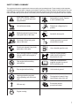
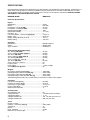
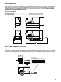
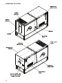
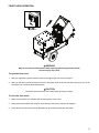
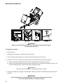
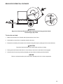
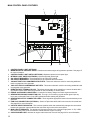
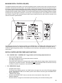
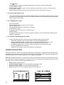
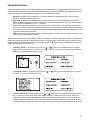
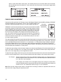
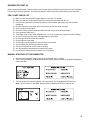
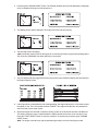
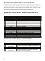
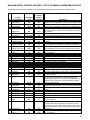
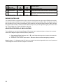
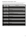
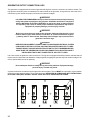
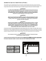
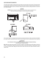
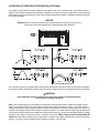
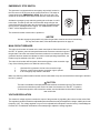
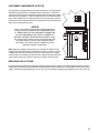
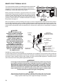
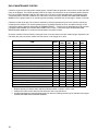
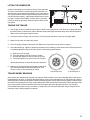
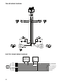
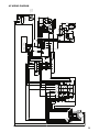
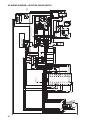
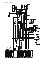
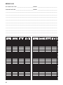


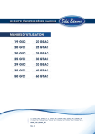
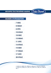


![DML-1200 [v04]](http://vs1.manualzilla.com/store/data/005824987_1-7e9516eac06e792a0e8f27802b417a45-150x150.png)