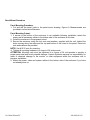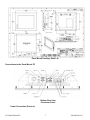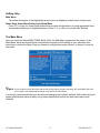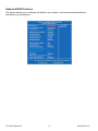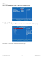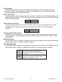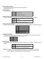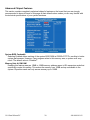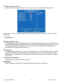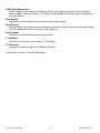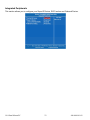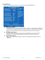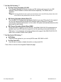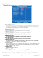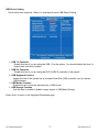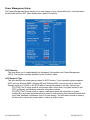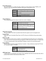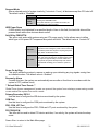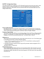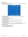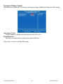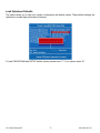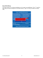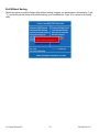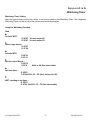
1
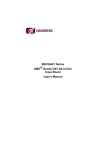
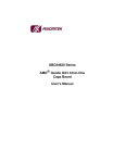
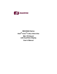
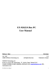
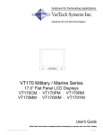
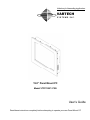
Solutions for Demanding Applications VARTECH S Y S T E M S I N C. 19.0” Panel Mount PC Model VTPC190P / PSS User’s Guide Read these instructions completely before attempting to operate your new Panel Mount PC Revision History Date 8/11/08 10/13/08 7/10/09 5/27/10 8/15/12 8/15/12 8/15/12 8/15/12 Rev No 00 01 02 03 04 04 04 04 19.0 Panel Mount PC Summary First Issue Revised panel mounting drawing Revised Detail A, connector view & system spec. Corrected DC power rating misprint Updated LCD Display Specs Updated Computer Specs Updated Power Specs Added Bios Section 2 Page 6 4, 6 & 7 5 4 4 5 10 - 42 486-0010-01-02 Safety Instructions Read the Safety Instructions carefully and keep it for use later. The chassis metalwork of the module must be installed properly to the main earthing termination for Class 1 equipment. Care must be exercised in the application of the system to prevent overheating. Ensure that the ambient temperature around the system does not exceed 60°C and provide adequate means of ventilation to achieve this. When cleaning cut off the electrical supply at all times. Never use liquid or aerosol detergent, use a soft damp cloth instead. Never insert anything metallic into the chassis openings. This may create an electric shock hazard or hazard from rotating fan blades. To avoid electric shock, never touch the inside of the system. There are no user adjustable components inside, only a qualified technician should open the system’s case. Openings in the system enclosure are to allow for ventilation. To prevent overheating, these openings should not be blocked or covered. If the system does not operate normally – in particular, if there are any unusual sounds or smells coming from it – disconnect it immediately. Do not put pressure on the LCD/LED panel screen because it is very fragile. Always handle the system with care when moving it. Take care that the system is disposed of correctly at the end of its life. If in doubt refer to your local ordinances or regulations for proper disposal. A socket-outlet shall be installed near the equipment and shall be easily accessible. Cleaning the LCD/LED monitor To clean the LCD/LED panel: Wipe the screen gently with a clean lens brush made of camel hair, or a soft, clean, lint free cloth. This is to remove dust and other particles without scratching the LCD/LED panel. If it is still not clean, then wipe with a damp lint free cloth and blow on it to dry. Do not clean the panel with a keton-type material (e.g. acetone), or ethyl toluene, ethyl acid, methyl or chloride. These may damage the LCD/LED panel. Do not apply pressure to the LCD/LED panel. 19.0 Panel Mount PC 3 486-0010-01-02 Standard Technical Specifications: Standard Monitor: Size / Type Native Resolution Contrast Ratio Viewing Angles Pixel Pitch Brightness (typical) Response Time (typical) Colors Supported 19.0” SXGA TFT LCD 1280 x 1024 800:1 Horizontal: 89° Vertical: 89° 0.294mm 300 cd/m² 8ms 16.7 million Computer System: Processor Intel Pentium Dual Core Processor T4500 2.30 GHz 800MHz FSB System Memory DDR2 533 DIMM 2 GB x 1 (expandable to 4GB) BIOS Phoenix-Award 16Mbit with RPL/PXE LAN Boot Hard Drive 500 GB 5400 RPM SATA (Optional 8, 16, 32, 64, 128, and 256GB SSD) Operating System Microsoft XP Professional (SP3) for Embedded Systems (Optional Windows 7 Professional 32 or 64 bit, Windows Embedded Standard 2009) Expansion Slots PCIe x 16 (Optional) I/O Ports – Back/Front 1 x PS/2 Keyboard 1 x PS/2 Mouse 2x RS-232; with +5V/+12V powered 1 x RS-232/422/485 (COM 1); with +5V/+12V powered 4 x Rear USB 2 x Front USB 2x Ethernet 2x IEEE1394 (Firewire) MIC-in & Line-out/Speaker-out Integrated Intel GME965 GMCH Gen 4 Graphics Graphics LAN Intel 82566DM 10/100/1000 (1st port) Intel 82573V 10/100/1000 (2nd port) DVD Drive (E-IDE / ATAPI) DVD-R, DVD+R, DVD-RW, DVD+RW, DVD-R DL, DVD+R9 CD-R, CD-RW Touch Screen Resistive Touch Screen Interface USB 19.0 Panel Mount PC 4 486-0010-01-02 Power & Operational Specifications: AC Models: 90 – 240VAC standard Power Input DC Models: 9-32 VDC, 15.0A max. Typical Power Consumption AC: 60W DC: 9V – 8.5A 12V – 4.5A 24V – 2.3A 32V – 1.6A Operational: -32°F to 140°F Temperature Humidity Storage: -4°F to 176°F Operational: 20 to 40°C, 90% RH NC Storage: 0°C to 60°C -20°C to 80°C 5 to 65°C, 28% RH NC Installation of Your Panel PC Packaged with each carton will be: 1 - VTPC190P / PSS 1 - AC Power Cable (Not included with DC option) 1 - #10-32 Mounting Hardware 1 - Users Guide (Printed or on CD) BEFORE MAKING ANY CONNECTIONS OR APPLYING POWER, FIRST READ THROUGH THE ENTIRE MANUAL 19.0 Panel Mount PC 5 486-0010-01-02 Panel Mount Procedure Panel Mounting Procedure: 1- Cut and drill the panel (refer to the panel mount drawing, Figure A). Measurements are provided in inches and millimeters. Panel Mounting Cutout: 1- If access to the bottom of the enclosure is not available following installation, attach the power and all necessary cables to the bottom side of the enclosure at this time. 2- Install the enclosure in the prepared cutout. 3- Secure the enclosure using the lock nuts and washers, supplied with the unit, behind the holes running along the sides and the top and bottom of the cutout in the panel. Extra lock nuts and washers are provided. NOTE: Use #10-32 nuts for mounting. 4- Tighten all mounting hardware to a torque of 24 inch-pounds. ATTENTION: Mounting nuts must be tightened to a torque of 24 inch-pounds to provide a proper panel seal and avoid potential damage. Vartech Systems assumes no responsibility for water or chemical damage to the monitor or other equipment within the enclosure due to improper installation. 5- Attach the power, video and system cables to the bottom side of the enclosure if you have not already done so. 19.0 Panel Mount PC 6 486-0010-01-02 Panel Mount Drawing: Detail –A– Connections to the Panel Mount PC Bottom Rear View - Connector Panel Power Connection (Power In) 19.0 Panel Mount PC 7 486-0010-01-02 AC Models: The Panel Mount PC includes an AC line cord which is 6ft long. The power input receptacle is located on the bottom rear panel of the system. DC Models: The Panel Mount PC with two binding posts, one red and one black. Red is for connecting +9-32VDC and black is for power ground. Connect to any DC power source that does not exceed 15A of current. (15A mini-blade fuse protected) Serial Connections (COM 1-3) The Panel Mount PC is supplied with three serial connectors configured for RS-232. The connector is a 9 pin female connectors and can be set up for any baud rate from 300 to 19.2 baud. The connector is located on the bottom panel of the system. Ethernet Connections (LAN 1-2) The Panel Mount PC is supplied with two integrated Ethernet connectors. The interface will support 10/100/1000 BaseT connection to a local area network (LAN). The Panel Mount PC is supplied with two RJ-45 female connectors located on the bottom panel of the system. USB Connections (USB 1-4) The Panel Mount PC is supplied with four USB 2.0 connectors located on the bottom front panel of the system. VGA Port The 15-pin female VGA connector can be used to connect to any analog VGA monitor. IEEE1394a (Firewire) The Panel PC is supplied with two IEEE1394a ports which feature high speed, high bandwidth which are hot pluggable to connect with IEEE1394 devices and peripherals. Turning the system On and Off Before connecting the Panel Mount PC to power, connect any peripheral devices. As a general rule, any peripheral device should only be connected or disconnected when the Panel Mount PC is off with the exception of any USB or 1394 peripheral. The Panel Mount PC is turned on using the main On-Off rocker switch located on the bottom rear panel. Once the Panel Mount PC main switch is turned on the computer power pushbutton switch must be depressed for Windows to start. Windows must be properly shut down before the main power switch is turned off to prevent the chance of corrupting files in the operating system. The Panel Mount PC is rated for continuous duty. However, to extend the life of the various components and conserve power, it is highly recommended that the system be properly shut down and power turned off when the Panel Mount PC is not in use. LCD Monitor Warm-up Time 19.0 Panel Mount PC 8 486-0010-01-02 All LCD/LED monitors need time to become thermally stable the first time you turn them on. Therefore, to achieve more accurate adjustments for parameters, allow the LCD/LED monitor to warm (be on) for at least 20 minutes before making any screen adjustments. Maintenance The Panel Mount PC is designed to provide optimum service and performance with minimal maintenance including the occasional external cleaning. For cleaning the Panel Mount PC enclosure follow the suggested guidelines. General – NEVER use abrasive cleaners or solvent-based cleaners!! Use a clean soft cloth. The Panel Mount PC should only be opened and serviced by a qualified technician. Keep the area around the Panel Mount PC clear and free of excessive dirt or other contaminants. Do not use water or any liquids on the Panel Mount PC. Before disposing, check state and local ordinances or return to manufacturer. 19.0 Panel Mount PC 9 486-0010-01-02 Award BIOS Utility The Phoenix-Award BIOS provides users with a built-in Setup program to modify basic system configuration. All configured parameters are stored in a battery-backed-up RAM (CMOS RAM) to save the Setup information whenever the power is turned off. Entering Setup There are two ways to enter the Setup program. You may either turn ON the computer and press <Del> immediately, or press the <Del> and/or <Ctrl>, <Alt>, and <Esc> keys simultaneously when the following message appears at the bottom of the screen during POST (Power on Self Test). TO ENTER SETUP PRESS DEL KEY If the message disappears before you respond and you still want to enter Setup, please restart the system to try it again. Turning the system power OFF and ON, pressing the “RESET” button on the system case or simultaneously pressing <Ctrl>, <Alt>, and <Del> keys can restart the system. If you do not press keys at the right time and the system doesn’t boot, an error message will pop out to prompt you the following information: PRESS <F1> TO CONTINUE, <CTRL-ALT-ESC> OR <DEL> TO ENTER SETUP Control Keys Up arrow Move cursor to the previous item Down arrow Left arrow Right arrow Move cursor to the next item Move cursor to the item on the left hand Move to the item in the right hand Main Menu -- Quit and delete changes into CMOS Status Page Setup Menu and Option Page Setup Menu -- Exit current page and return to Main Menu Increase the numeric value or make changes Decrease the numeric value or make changes Esc key PgUp/“+” key PgDn/““ key F1 key (Shift) F2 key F3 key F4 key F5 key F6 key F7 key F8 key F9 key F10 key 19.0 Panel Mount PC General help, only for Status Page Setup Menu and Option Page Setup Menu Change color from total 16 colors. F2 to select color forward, (Shift) F2 to select color backward Reserved Reserved Restore the previous CMOS value from CMOS, only for Option Page Setup Menu Load the default CMOS value from BIOS default table, only for Option Page Setup Menu Load the Setup default, only for Option Page Setup Menu Reserved Reserved Save all the CMOS changes, only for Main Menu 10 486-0010-01-02 Getting Help Main Menu The online description of the highlighted setup function is displayed at the bottom of the screen. Status Page Setup Menu/Option Page Setup Menu Press <F1> to pop out a small Help window that provides the description of using appropriate keys and possible selections for highlighted items. Press <F1> or <Esc> to exit the Help Window. The Main Menu Once you enter the Award BIOS CMOS Setup Utility, the Main Menu appears on the screen. In the Main Menu, there are several Setup functions and a couple of Exit options for your selection. Use arrow keys to select the Setup Page you intend to configure then press <Enter> to accept or enter its sub-menu. NOTE: If your computer cannot boot after making and saving system changes with Setup, the Award BIOS will reset your system to the CMOS default settings via its built-in override feature. It is strongly recommended that you should avoid changing the chipset’s defaults. Both Award and your system manufacturer have carefully set up these defaults that provide the best performance and reliability. 19.0 Panel Mount PC 11 486-0010-01-02 Standard CMOS Setup Menu The Standard CMOS Setup Menu displays basic information about your system. Use arrow keys to highlight each item, and use <PgUp> or <PgDn> key to select the value you want in each item. Date The date format is <day>, <date> <month> <year>. Press <F3> to show the calendar. day date month year It is determined by the BIOS and read only, from Sunday to Saturday. It can be keyed with the numerical/ function key, from 1 to 31. It is from January to December. It shows the current year of BIOS. Time This item shows current time of your system with the format <hour> <minute> <second>. The time is calculated based on the 24-hour military-time clock. For example, 1 p.m. is 13:00:00. 19.0 Panel Mount PC 12 486-0010-01-02 IDE Channel 0~3 Master/IDE Channel 0~2 Slave These items identify the types of each IDE channel installed in the computer. There are 45 predefined types (Type 1 to Type 45) and 2 user’s definable types (Type User) for Enhanced IDE BIOS. Press <PgUp>/<+> or <PgDn>/<> to select a numbered hard disk type, or directly type the number and press <Enter>. Please be noted your drive’s specifications must match the drive table. The hard disk will not work properly if you enter improper information. If your hard disk drive type does not match or is not listed, you can use Type User to manually define your own drive type. If selecting Type User, you will be asked to enter related information in the following items. Directly key in the information and press <Enter>. This information should be provided in the documentation from your hard disk vendor or the system manufacturer. If the HDD interface controller supports ESDI, select “Type 1”. If the HDD interface controller supports SCSI, select “None”. If the HDD interface controller supports CD-ROM, select “None”. CYLS. HEADS PRECOMP number of cylinders LANDZONE SECTORS number of heads MODE write precom landing zone number of sectors HDD access mode If there is no hard disk drive installed, select NONE and press <Enter>. Drive A Select the type of floppy drive installed in your system, and the default setting is “None”. Video Select the display adapter type for your system. 19.0 Panel Mount PC 13 486-0010-01-02 Halt On This item determines whether the system will halt or not, if an error is detected while powering up. No errors All errors All, But Keyboard All, But Diskette All, But Disk/Key The system booting will halt on any errors detected. (default) Whenever BIOS detects a non-fatal error, the system will stop and you will be prompted. The system booting will not stop for a keyboard error; it will stop for other errors. The system booting will not stop for a disk error; it will stop for other errors. The system booting will not stop for a keyboard or disk error; it will stop for other errors. Press <Esc> to return to the Main Menu page. 19.0 Panel Mount PC 14 486-0010-01-02 Advanced BIOS Features This section allows you to configure and improve your system, to set up some system features according to your preference. 19.0 Panel Mount PC 15 486-0010-01-02 CPU Feature Scroll to this item and press <Enter> to view the CPU Feature sub menu. Hard Disk Boot Priority Scroll to this item and press <Enter> to view the sub menu to decide the disk boot priority. Press <Esc> to return to the Advanced BIOS Features page. 19.0 Panel Mount PC 16 486-0010-01-02 Virus Warning This function allows you to choose the VIRUS Warning feature for IDF Hard Disk boot sector protection. If this function is enabled and attempt to write data into this area, BIOS will show a warning message on screen and alarm beep. CPU L1 & L2 Cache These two options speed up memory access. However, it depends on the CPU/chipset design. The default setting is “Enabled”. CPUs without built-in internal cache will not provide the “CPU Internal Cache” item on the menu. Enabled Disabled Enable cache Disable cache Quick Power On Self Test This option speeds up Power on Self Test (POST) after you turn on the system power. If set as Enabled, BIOS will shorten or skip some check items during POST. The default setting is “Enabled”. Enabled Disabled Enable Quick POST Normal POST First/Second/Third Boot Device These items let you select the 1st, 2nd, and 3rd devices that the system will search for during its boot-up sequence. The wide range of selection includes Floppy, LS120, ZIP100, HDD0~3, SCSI, and CDROM. Boot Other Device This item allows users to enable or disable the boot device not listed in the First/Second/Third boot devices option above. The default setting is “Enabled”. Boot Up Floppy Seek During POST, BIOS will determine the floppy disk drive type, 40 or 80 tracks. The 360Kb type is 40 tracks while 720Kb, 1.2MB and 1.44MB are all 80 tracks. The default value is “Enabled”. Enabled Disabled 19.0 Panel Mount PC BIOS searches for floppy disk drive to determine if it is 40 or 80 tracks. Please be noted BIOS cannot differentiate 720K, 1.2M or 1.44M drive type as they all are 80 tracks. BIOS will not search for the type of floppy disk drive by track number. There will be no warning message displayed if the installed drive is 360K. 17 486-0010-01-02 Boot Up NumLock Status Set the the Num Lock status when the system is powered on. The default value is “On”. Gate A20 Option The default value is “Fast”. Normal Fast The A20 signal is controlled by keyboard controller or chipset hardware. Default: Fast. The A20 signal is controlled by Port 92 or chipset specific method. Typematic Rate Setting This item determines the typematic rate of the keyboard. The default value is “Disabled”. Enabled Disabled Enable typematic rate and typematic delay programming. Disable typematic rate and typematic delay programming. The system BIOS will use default value of these 2 items, controlled by keyboard. Typematic Rate (Chars/Sec) This option refers to character numbers typed per second by the keyboard. The default value is “6”. 6 8 10 12 15 20 24 30 6 characters per second 8 characters per second 10 characters per second 12 characters per second 15 characters per second 20 characters per second 24 characters per second 30 characters per second Typematic Delay (Msec) This option defines how many milliseconds must elapse before a held-down key begins generating repeat characters. The default value is “250”. 250 500 750 1000 250 msec 500 msec 750 msec 1000 msec Security Option This item allows you to limit access to the system and Setup, or just to Setup. The default value is “Setup”. System Setup If a wrong password is entered at the prompt, the system will not boot, the access to Setup will be denied, either. If a wrong password is entered at the prompt, the system will boot, but the access to Setup will be denied. NOTE: To disable the security, select PASSWORD SETTING at Main Menu and then you will be asked to enter a password. Do not type anything, just press <Enter> and it will disable the security. Once the security is disabled, the system will boot and you can enter Setup freely. 19.0 Panel Mount PC 18 486-0010-01-02 APIC Mode Use this item to enable or disable APIC (Advanced Programmable Interrupt Controller) mode that provides symmetric multi-processing (SMP) for systems. MPS Version Control For OS This item specifies the version of the Multiprocessor Specification (MPS). Version 1.4 has extended configuration tables to improve support for multiple PCI bus configurations and provide future expandability. Small Logo <EPA> Show If enabled, the EPA logo will appear during system booting up; if disabled, the EPA logo will not appear. Press <Esc> to return to the Main Menu page. 19.0 Panel Mount PC 19 486-0010-01-02 Advanced Chipset Features This section contains completely optimized chipset’s features on the board that you are strongly recommended to leave all items on this page at their default values unless you are very familiar with the technical specifications of your system hardware. System BIOS Cacheable Selecting Enabled allows caching of the system BIOS ROM at F0000h-FFFFFh, resulting in better system performance. However, if any program writes to this memory area, a system error may result. The default value is “Disabled”. Memory Hole At 15M-16M Enabling this feature reserves 15MB to 16MB memory address space to ISA expansion cards that specifically require this setting. This makes the memory from 15MB and up unavailable to the system. Expansion cards can only access memory up to 16MB. 19.0 Panel Mount PC 20 486-0010-01-02 PCI Express Root Port Func Scroll to this item and press <Enter> to view the sub menu to decide the PCI Express Port. Press <Esc> to return to the Advanced Chipset Featurs page, and press it again, return to the Main Menu page. *** VGA Setting *** PEG/Onchip VGA Control This setting allows you to select whether to use the onchip graphics processor or the PCI Express card. When set to [Auto], the BIOS will check if a PCI Express graphics card is installed or not. If a PCI Express graphics card is detected, the board will boot up using that card. Otherwise, it is defaulted to the onchip graphics processor. PEG Force X1 This BIOS feature allows you to convert a PCI Express X16 slot into a PCI Express X1 slot. When this item is enabled, the PCI Express X16 slot will be forced to run in the PCI Express X1 mode. When this item is disabled, the PCI Express X16 slot will be allowed to run its normal PCI Express X16 mode. On-Chip Frame Buffer Size Use this item to set the VGA frame buffer size. DVMT Mode DVMT (Dynamic Video Memory Technology) helps you select the video mode. 19.0 Panel Mount PC 21 486-0010-01-02 DVMT/Fixed Memory Size DVMT (Dynamic Video Memory Technology) allows you to select a maximum size of dynamic amount usage of the video memory. The system would configure the video memory dependent on your application. Boot Display This item is to select Display Device that the screen will be shown. Panel Scaling This item shows the setting of panel scaling and operates the scaling function that the panel output can fit the screen resolution connected to the output port. Panel Number This item is to select panel resolution that you want. TV Standard This item is to select the output mode of TV Standard. TV Connector This item is to select the type of TV display connector. Press <Esc> to return to the Main Menu page. 19.0 Panel Mount PC 22 486-0010-01-02 Integrated Peripherals This section allows you to configure your SuperIO Device, IDE Function and Onboard Device. 19.0 Panel Mount PC 23 486-0010-01-02 OnChip IDE Device Scroll to this item and press <Enter> to view the sub menu OnChip IDE Device. IDE HDD Block Mode Block mode is also called block transfer, multiple commands, or multiple sector read/write. If your IDE hard drive supports block mode (most new drives do), select Enabled for automatic detection of the optimal number of block read/writes per sector the drive can support. IDE DMA transfer access Automatic data transfer between system memory and IDE device with minimum CPU intervention. This improves data throughput and frees CPU to perform other tasks. LEGACY Mode Support Legacy mode support allows devices to function in an operating environment that is not USB-aware. 19.0 Panel Mount PC 24 486-0010-01-02 *** On-Chip PATA Setting *** On-Chip Primary/Secondary PCI IDE The integrated peripheral controller contains an IDE interface with support for two IDE channels. Select Enabled to activate each channel separately. The default value is “Enabled”. NOTE: Choosing Disabled for these options will automatically remove the IDE Primary Master/ Slave PIO and/or IDE Secondary Master/Slave PIO items on the menu. IDE Primary/Secondary Master/Slave PIO The four IDE PIO (Programmed Input/Output) fields let you set a PIO mode (0-4) for each of the four IDE devices that the onboard IDE interface supports. Modes 0 to 4 provide successively increased performance. In Auto mode, the system automatically determines the best mode for each device. IDE Primary/Secondary Master/Slave UDMA Select the mode of operation for the IDE drive. Ultra DMA-33/66/100/133 implementation is possible only if your IDE hard drive supports it and the operating environment includes a DMA driver. If your hard drive and system software both support Ultra DMA-33/66/100/133, select Auto to enable UDMA mode by BIOS. *** On-Chip Serial ATA Setting *** SATA Mode There are these options for you to set up SATA mode: IDE, RAID or AHCI. On-Chip Serial ATA Use this item to enable or disable the built-in on-chip serial ATA. Press <Esc> to return to the Integrated Peripherals page. 19.0 Panel Mount PC 25 486-0010-01-02 Super IO Device Scroll to this item and press <Enter> to view the sub menu Super IO Device. Onboard FDC Controller Select Enabled, if your system has a floppy disk controller (FDC) installed on the system board and you want to use it. If you install and-in FDC or the system has no floppy drive, select Disabled in this field. Options: Enabled and Disabled. Onboard Serial Port 1/2 Select an address and corresponding interrupt for the serial port. Onboard Serial Port 3 This item assigns which I/O address to access onboard serial port 3. Serial Port 3 Use IRQ This item selects a corresponding interrupt for the third serial port. Onboard Serial Port 4 This item assigns which I/O address to access onboard serial port 4. Serial Port 4 Use IRQ This item selects a corresponding interrupt for the fourth serial port. Onboard Paralellel Port This item allows you to determine the I/O address for onboard parallel port. Options are: “378H/IRQ7”, “278H/IRQ5”, “3BC/IRQ7” and “Disabled”. Parallel Port Mode Select an operating mode for the onboard parallel (printer) port. Select Normal unless your hardware and software require another mode in this field. Options are: “EPP1.9”, “ECP”, “SPP”, “ECPEPP1.7” and “EPP1.7”. EPP Mode Select Select EPP port type 1.7 or 1.9. ECP Mode Use DMA Select a DMA channel for the parallel port while using the ECP mode. Press <Esc> to return to the Integrated Peripherals page, and press it again to the Main Menu. 19.0 Panel Mount PC 26 486-0010-01-02 USB Device Setting Scroll to this item and press <Enter> to view the sub menu USB Device Setting. USB 1.0 Controller Enable this item if you are using the USB 1.0 in the system. You should disable this item if a higher-level controller is added. USB 2.0 Controller Enable this item if you are using the EHCI (USB2.0) controller in the system. USB Keyboard Function Enable this item if the system has a Universal Serial Bus (USB) controller, and you have a USB keyboard. USB Mouse Function Enable this item to boot the hard drive by a USB mouse. USB Storage Function Use this item to enable or disable Legacy suppor of USB Mass Storage. Press <Esc> to return to the Integrated Peripherals page. 19.0 Panel Mount PC 27 486-0010-01-02 Power Management Setup The Power Management Setup allows you to save energy of your system effectively. It will shut down the hard disk and turn OFF video display after a period of inactivity. ACPI Function This item allows you to enable/disable the Advanced Configuration and Power Management (ACPI). The function is always defaulted in the “Enabled” mode. ACPI Suspend Type This item specifies the power saving modes for ACPI function. If your operating system supports ACPI, such as Windows 98SE, Windows ME and Windows 2000, you can choose to enter the Standby mode in S1 (POS) or S3 (STR) fashion through the setting of this field. Options are: [S1 (POS)] The S1 sleep mode is a low power state. In this state, no system context is lost (CPU or chipset) and hardware maintains all system contexts. [S3 (STR)] The S3 sleep mode is a lower power state where the information of system configuration and open applications/files is saved to main memory that remains powered while most other hardware components turn off to save energy. The information stored in memory will be used to restore the system when a “wake up” event occurs. 19.0 Panel Mount PC 28 486-0010-01-02 Power Management This option allows you to select the type (or degree) of power saving for Doze, Standby, and Suspend modes. The table below describes each power management mode: Max Saving User Define Min Saving Disabled It is maximum power savings, only available for SL CPUs. The inactivity period is 1 minute in each mode. It sets each mode. Select time-out periods in the PM Timers section. It is minimum power savings. The inactivity period is 1 hour in each mode (except the hard drive). Default value Video Off Method This setting determines the manner in which the monitor is blanked. V/H SYNC+Blank DPMS Blank Screen It turns OFF vertical and horizontal synchronization ports and writes blanks to the video buffer. Select this option if your monitor supports the Display Power Management Signaling (DPMS) standard of the Video Electronics Standards Association (VESA). Use the supplied software for your video subsystem to select video power management values. The System only writes blanks to the video buffer. Video Off In Suspend This item defines if the video is powered down when the system is put into suspend mode. Suspend Type If this item is set to the default Stop Grant, the CPU will go into Idle Mode during power saving mode. Moden Use IRQ If you want an incoming call on a modem to automatically resume the system from a powersaving mode, use this item to specify the interrupt request line (IRQ) used by the modem. You might have to connect the fax/modem to the board Wake On Modem connector for working this feature. Suspend Mode After the selected period of system inactivity (1 minute to 1 hour), all devices except the CPU shut off. The default value is “Disabled”. Disabled 1/2/4/6/8/10/2 0/30/40 Min/1 Hr System will never enter SUSPEND mode Defines the continuous idle time before the system entering SUSPEND mode. If any item defined in (J) is enabled & active, SUSPEND timer will be reloaded HDD Power Down If HDD activity is not detected for the length of time specified in this field, the hard disk drive will be powered down while all other devices remain active. 19.0 Panel Mount PC 29 486-0010-01-02 Suspend Mode After a selected period of system inactivity (1 minute to 1 hour), all devices except the CPU shut off. The default value is “Disabled”. Disabled 1/2/4/6/8/10/2 0/30/40 Min/1 Hr The System will never enter the SUSPEND mode. It defines continuous idle time before the system entering the SUSPEND mode. If any item defined in (J) is enabled and active, the SUSPEND timer will be reloaded. HDD Power Down If HDD activity is not detected for a specified length of time in this field, the hard disk drive will be powered down while other devices remain active. Soft-Off by PWR-BTTN This option only works with systems using an ATX power supply. It also allows users to define which type of soft power OFF sequence the system will follow. The default value is “Instant-Off”. Instant-Off Delay 4 Sec. This option follows the conventional manner of system performance when turning the power to OFF. Instant-Off is a software power OFF sequence requiring the power supply button is switched to OFF. Upon the system’s turning OFF through the power switch, this option will delay the complete system power OFF sequence approximately 4 seconds. Within this delay period, the system will temporarily enter into the Suspend Mode enabling you to restart the system at once. Power On by Ring This option allows the system to resume or wake up upon detecting any ring signals coming from an installed modem. The default value is “Enabled”. Resume by Alarm If enable this item, the system can automatically resume after a fixed time in accordance with the system’s RTC (realtime clock). ** Reload Global Timer Events ** Global Timer (power management) events can prevent the system from entering a power saving mode or can awaken the system from such a mode. Primary/Secondary IDE 0/1 Use this item to configure the IDE devices monitored by the system. COM Port Use this item to configure the COM ports monitored by the system. FDD, COM, LPT Port Use this item to configure the FDD, COM and LPT ports monitored by the system. PCI PIRQ[A-D]# This item can be used to detect PCI device activities; if no activity, the system will enter the sleep mode. Press <Esc> to return to the Main Menu page. 19.0 Panel Mount PC 30 486-0010-01-02 PnP/PCI Configuration Setup This section describes the configuration of PCI (Personal Computer Interconnect) bus system, which allows I/O devices to operate at speeds close to the CPU speed while communicating with other important components. This section covers very technical items that only experienced users could change default settings. Reset Configuration Data Normally, you leave this item Disabled. Select Enabled to reset Extended System Configuration Data (ESCD) when you exit Setup or if installing a new add-on cause the system reconfiguration a serious conflict that the operating system cannot boot. Options: Enabled, Disabled. Resources Controlled By The Award Plug and Play BIOS can automatically configure all boot and Plug and Play-compatible devices. If you select Auto, all interrupt request (IRQ), DMA assignment, and Used DMA fields disappear, as the BIOS automatically assigns them. The default value is “Manual”. IRQ Resources When resources are controlled manually, assign each system interrupt to one of the following types in accordance with the type of devices using the interrupt: 1. Legacy ISA Devices compliant with the original PC AT bus specification, requiring a specific interrupt (such as IRQ4 for serial port 1). 2. PCI/ISA PnP Devices compliant with the Plug and Play standard, whether designed for PCI or ISA bus architecture. The default value is “PCI/ISA PnP”. PCI/VGA Palette Snoop Some non-standard VGA display cards may not show colors properly. This item allows you to set whether MPEG ISA/VESA VGA Cards can work with PCI/VGA or not. When enabled, a PCI/VGA can work with a MPEG ISA/VESA VGA card; when disabled, a PCI/VGA cannot work with a MPEG ISA/VESA Card. 19.0 Panel Mount PC 31 486-0010-01-02 ** PCI Express relative items ** Maximum Payload Size When using DDR SDRAM and Buffer size selection, another consideration in designing a payload memory is the size of the buffer for data storage. Maximum Payload Size defines the maximum TLP (Transaction Layer Packet) data payload size for the device. Press <Esc> to return to the Main Menu page. 19.0 Panel Mount PC 32 486-0010-01-02 PC Health Status This section supports hardware monitering that lets you monitor those parameters for critical voltages, temperatures and fan speed of the board. Shutdown Temperature It helps you set the maximum temperature they system can reach before powering down. Current SYSTEM Temperature Show you the current system1 temperature. Current CPU Temperature The current system CPU temperature will be automatically detected by the system. Current GMCH Temperature The current GMCH temperature will be automatically detected by the system. Current CPU FAN Speed These optional and read-only items show current speeds in RPM (Revolution per Minute) for the CPU fan and chassis fan as monitored by the hardware monitoring IC. Current SYS FAN Speed Show you the current system fan1 temperature. Vcore +3.3V/+5V/+12V/VBAT(V)/5VSB Show you the voltage of +3.3V/+5V/+12V. 19.0 Panel Mount PC 33 486-0010-01-02 Frequency/Voltage Control This section is to control the CPU frequency and Supply Voltage, DIMM OverVoltage and AGP voltage. Auto Detect PCI Clk The item enables or disables the auto detection of the PCI clock. Spread Spectrum This item is to adjust extreme values of the pulse for EMI test. Press <Esc> to return to the Main Menu page. 19.0 Panel Mount PC 34 486-0010-01-02 Load Optimized Defaults This option allows you to load your system configuration with default values. These default settings are optimized to enable high performance features. To load CMOS SRAM with SETUP default values, please enter “Y”. If not, please enter “N”. 19.0 Panel Mount PC 35 486-0010-01-02 Set Supervisor/User Password You can set a supervisor or user password, or both of them. The differences between them are: 1. Supervisor password: You can enter and change the options on the setup menu. 2. User password: You can just enter, but have no right to change the options on the setup menu. When you select this function, the following message will appear at the center of the screen to assist you in creating a password. ENTER PASSWORD Type a maximum eight-character password, and press <Enter>. This typed password will clear previously entered password from the CMOS memory. You will be asked to confirm this password. Type this password again and press <Enter>. You may also press <Esc> to abort this selection and not enter a password. To disable the password, just press <Enter> when you are prompted to enter a password. A message will confirm the password is getting disabled. Once the password is disabled, the system will boot and you can enter Setup freely. PASSWORD DISABLED When a password is enabled, you have to type it every time you enter the Setup. It prevents any unauthorized persons from changing your system configuration. Additionally, when a password is enabled, you can also require the BIOS to request a password every time the system reboots. This would prevent unauthorized use of your computer. You decide when the password is required for the BIOS Features Setup Menu and its Security option. If the Security option is set to “System”, the password is required during booting up and entry into the Setup; if it is set as “Setup”, a prompt will only appear before entering the Setup. 19.0 Panel Mount PC 36 486-0010-01-02 Save & Exit Setup This section allows you to determine whether or not to accept your modifications. Type “Y” to quit the setup utility and save all changes into the CMOS memory. Type “N” to bring you back to the Setup utility. 19.0 Panel Mount PC 37 486-0010-01-02 Exit Without Saving Select this option to exit the Setup utility without saving changes you have made in this session. Type “Y”, and it will quit the Setup utility without saving your modifications. Type “N” to return to the Setup utility. 19.0 Panel Mount PC 38 486-0010-01-02 AppendixA Watchdog Timer Watchdog Timer Setting After the system stops working for a while, it can be auto-reset by the Watchdog Timer. The integrated Watchdog Timer can be set up in the system reset mode by program. Using the Watchdog Function Start Un-Lock WDT: O 2E 87 ; Un-lock super I/O O 2E 87 ; Un-lock super I/O Select Logic device: O 2E 07 O 2F 08 Activate WDT: O 2E 30 O 2F 01 Set Second or Minute : O 2E F5 O 2F N N=00 or 08 (See below table) Set base timer : O 2E F6 O 2F M=00,01,02,…FF (Hex) ,Value=0 to 255 WDT counting re-set timer : O 2E F6 O 2F M ; M=00,01,02,…FF (See below table) 19.0 Panel Mount PC 39 486-0010-01-02 ; IF to disable WDT: O 2E 30 O 2F 00 ; Can be disable at any time Timeout Value Range 1 to 255 Minute / Second Program Sample 2E, 87 2E, 87 2E, 07 2F, 08 Logical Device 8 2E, 30 Activate 2F, 01 2E, F5 2F, N Set Minute or Second N=08 (Min),00(Sec) 2E, F6 2F, M 19.0 Panel Mount PC Set Value M = 00 ~ FF 40 486-0010-01-02 AppendixB Digital I/O Using the Digital Input Function Start Un-Lock SuperI /O: O 2E 87 ; Un-lock super I/O O 2E 87 ; Un-lock super I/O SelectMultiplexed pin to GPIO Function: O 2E 2A O 2F FF Select Logic device: O 2E 07 O 2F 07 Activate Logic Device: O 2E 30 O 2F 01 Select GPI Function: O 2E F0 O 2F E0 (for 3 IN/5 OUT) ( When set to a '1', respective GPIO port is programmed as an input port. When set to a '0', respective GPIO port is programmed as an output port.) Read Data: O 2E F1 I 2F XX ( XX is input Data;if no input source,the value is FF) 19.0 Panel Mount PC 41 486-0010-01-02 Using the Digital Output Function Start Un-Lock SuperI /O: O 2E 87 ; Un-lock super I/O O 2E 87 ; Un-lock super I/O SelectMultiplexed pin to GPIO Function: O 2E 2A O 2F FF Select Logic device: O 2E 07 O 2F 07 Activate Logic Device: O 2E 30 O 2F 01 Select GPO Function: O 2E F0 O 2F E0 (for 3 IN/5 OUT) ( When set to a '1', respective GPIO port is programmed as an input port. When set to a '0', respective GPIO port is programmed as an output port.) Output Data: O 2E F1 O 2F XX=00,01,02,…FF (XX is Output Data) For Additional Assistance Contact Your VarTech Sales Representative Vartech Systems, Inc. 11529 Sun Belt Ct. Baton Rouge, LA 70809 800-223-8050 Fax: 225-297-2440 www.vartechsystems.com 19.0 Panel Mount PC 42 486-0010-01-02