1
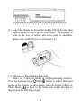
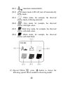
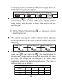
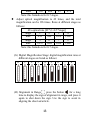
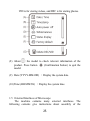
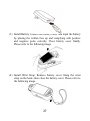
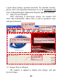
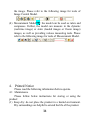
VT300 User’s Guide Digital Portable Microscope Version 1.4A Contents 1. 1.1 1.2 1.3 1.4 1.5 2. 2.1 2.2 2.3 2.4 3. 3.1 3.2 3.3 3.4 3.5 3.6 4. Products Introduction ...................................... 3 Packing Contents ................................... 3 Functions of Microscope........................ 3 Operation of Microscope ....................... 6 Microscope Programming Functions ..... 8 External Interfaces of Microscope ....... 25 Program Installation ...................................... 28 Insert Installation CD (Step 1) ............. 28 Install Application Program (Step 2) ... 29 Install Driver (Step 3) .......................... 29 Quit Installation Program (Step 4) ....... 29 Operate Application Program ........................ 29 Video Preview Window ....................... 30 Images Preview Window ..................... 30 Main Menu ........................................... 31 Main Button ......................................... 31 Files List .............................................. 33 Special Functional Modules ................. 33 Printed Notice ................................................ 34 1 4.1 4.2 4.3 Maintenance ......................................... 34 Product Sizes........................................ 35 Safety Instructions ............................... 36 2 1. Products Introduction 1.1 Packing Contents Objects packed inside the box include one host and ten fittings as follows. Please charge the Li-ion battery for 6 to 8 hours for the first time. Name Qty Name Qty Host of Portable 1 Li-ion Battery 1 Microscope USB1.1Transmission 1 User‟s Guide 1 Line Adaptor 1 Installation CD 1 Protection Bag 1 Wrist Strap 1 Cleaning Cloth 1 Supporter 1 Calibrator 1 1.2 Functions of Microscope Microscope appearance is composed of buttons, transmission and storage interfaces. For the functions of interfaces, please refer to the following contents: (1) Camera/Video REC : the button is applied to photograph in observing mode [please refer to item (1) of Section 1.4]. Press the button for a long time to enter/quit Comparison mode. In the Video Play mode, it can open video files 3 [please refer to item (2) of Section 1.4]. In Video REC mode [please refer to item (3) of Section 1.4], the button is used to start/stop recording video. (2) Zoom Out : the button is applied to zoom out digital image [please refer to (F)and (G) of item (1) of Section 1.4]. (3) Zoom In : the button is applied to zoom in digital image. (4) Charging Display Light : The red light is to show the charging status if it is on. The red light will turn off when the charging is completed [please refer to (G) of item (1) of Section 1.4]. (5) Power Supply Display Light : a green light to show the machine is switched on. (6) Power Supply : press the button for 3 seconds to switch on/off the machine (7) Progressive-Brightness of Lights / : brightness can be adjusted at 8 levels [please refer to (D) of item (1) of Section 1.4]. In observing mode, the button is used to increase brightness of illumination (auxiliary sources). In the video 4 play mode the button is used for stop playing video. In other modes, it is used for choosing „up‟. (8) Select „right ‟ button: Press the button for 2 seconds to show Crossing Alignment in the center of the LCD Display. Or the button is used to next sequent „right‟ function. (9) Diminishing-Brightness of Lights / : the button is used to decrease brightness of illumination. Press the button for 2 seconds to switch to the Scene mode. [please refer to ( c ) of item (1) of Section 1.4]. Or the button is used to next sequent „down‟ function. (10) Select „left ‟ button: Press the button for 2 seconds to show Alignment in Range in the center of the LCD Display. Or the button is used to next sequent „left‟ function. (11) Confirmation Button : a switching button between special effects under observing mode and video recording mode. [please refer to (C) of item (1) of Section 1.4]. (12) Function Menu /Delete : after entering observing mode, press the button to skip to the Function Menu. In the review “Album” mode, press the button to delete photos. In the “Video Play” mode, it is used for delete the video. (13) Preview Photos : Press the button to preview photos in observing mode, and back to previous level or exit image in other modes. (14) Display Screen: To display image pictures. (15) Wheel Focus: a button to adjust optical focus [please refer to item(1) of Section 1.3and (E) of item (1) of Section 1.4]. The indicator is to select the times of magnification. 5 (16) Lens: the lens is applied to photography. (17) Battery Container: Where is the Li-ion battery put. [please refer to item (5) of Section 1.5]. (18) RESET Hole: in case the machine stops (which means no reaction in the image by pressing any button), insert slender clip into the hole to trigger the RESET button. (19) USB Connection Port: the port is applied to connect USB device to computer [please refer to item (6) of Section 1.4 and item (1) of Section 1.5]. (20) Handing Hole: a hanging hole for the Wrist Strap [please refer to item (4) of Section 1.5] 1.3 Operation of Microscope 6 First, please choose long shot or flush-way shot, then adjust the focus button. (1) Focus way: the focus dial is labeled to indicate the magnification amount (10x, 40x, and long shot). Rotate the wheel of focus to position (A) is for long shot, to (B) is low optical magnification (10x), and to (C)is High optical magnification (40x). Adjust photograph distance (height) to get one to ten times of magnification consecutively. Rotate the dial to right for smaller magnification, and to the left for larger magnification. You may find symbol represents the magnification rate. Please see below image, the indicator is under the position of 10x ( ) magnification. (2) Horizontal contact: there are two focus points (10x & 40x) in horizontal-contact observation, slightly tuning theblack indicator so that to get the clearest image quality 7 (3) Long Shot: Rotate the Focus dial next to 10X‟s right side, then slightly tuning so that to get the best image. Photography is same as the way of camera and scene mode is selectable. [please refer to (B) of item (1) of Section 1.4]. 1.4 Microscope Programming Functions There are 8 function modes in the programming interface. Press the Function Menu /Delete button to switch functional modes in the Camera. In other modes, press the button of Preview Photo /Back to back to the Menu and switch function as displayed in the following image: 8 (1) Camera : Observation mode. Please refer to the above image. Small icons are used to represent function modes. (A) Mode : the machine is in observing mode. (B) Scene Mode : Press the button for a long time to switch the six scene modes and select the modes by using buttons of / / / . 9 (B-1) : Automatic mode(default). (B-2) :Camera mode. LED will turn off automatically in this mode. (B-3) : White mode, for example, the observed articles made of shining materials. (B-4) : Grey mode, for example, the observed articles with light colors. (B-5) : Dark Grey mode, for example, the observed articles with dark colors. (B-6) : Black mode, for example, the observed articles with dark black. (C) Special Effects : press button to choose the following special effects models in observing model: 10 Normal Grey Scale : shows by grey scale to simplify and easily identify images. Reversed-phase : shows by complementary colors to strengthen faint-colored or over-lighted image. Relief : Outstanding show the edge and filter out non-marked image. : general model without any special effect. (D) Brightness of Lights : press and adjust brightness of lights in the observing model. brightness is divided into the following 8 levels: level 0 (no light) level 4 level 1 level 5 level 2 level 6 level 3 level 7 (most bright) to The (E) Battery Status : the state is divided into three types including Battery in Using, Battery Charging and USB Power Supply. Battery in Using : only use the battery without any external power supply. Full High Medium Low Battery Charging : use USB power supply to charge the battery. The charging will stop if the battery is full, and only USB power supply will be used. Power supply applied 11 to charging can be provided by USB power supply device or USB connection port of computer. The following images are presented while charging USB Source : the graphic will be presented under two circumstances. One is insert USB power supply without using battery, and the other is insert USB source and use full-charged. (F) Optical Digital Magnification magnification rate. : represents current The optical zooming rate will be changed while adjusting the black indicator on the wheel of Focus. Please refer to the following. Long Shot Low Mag.(L) High Mag.(H) Digital magnification rate can be adjusted by the buttons of zoom out ( ) and zoom in ( ). The magnification is divided into 8 stages and can be up to 4 times with 0.5 times per stage. The image can be enlarged to 47 times when combining optical and digital magnifications. The rates at different stage are as follows: 10x optical rate [10* (1+0.5*stage)] Stage 1 2 3 4 Rate 15x 20x 25x 30x Stage 5 6 7 8 12 Rate 35x 40x 45 47x Note: this formula is for 0-7 stages. Adjust optical magnification to 42 times, and the total magnification can be 196 times. Rates at different stages as follows: 42x optical rate [42* (1+0.5*stage)] Stage 1 2 3 4 Rate 63x 84x 105x 126x Stage 5 6 7 8 Rate 147x 168x 189x 196x Note: this formula is for 0-7 stages. (G) Digital Magnification Stage: digital magnification rates at different stages are listed as follows: 0 1 2 3 4 5 6 7 8 (H) Alignment in Range : press the button for a long time to display the sign of alignment in range, and press it again to shut down the sign. Use the sign to assist in aligning the observed article. 13 (I) Crossing Alignment : Press the button for a long time to display the sign of crossing alignment, and press it again to shut down the sign. Use the sign to show the position in which the lens of machine is located and make the alignment more conveniently in observation . (J) Scale: Press the button (Confirmation button) for a long time to display the scale, and press it long time again to shut down the scale. Press the button of without releasing to select different scales. After selection, release the button. The two types of scales are showed as follows: L-shaped Scale Crossing Scale The scale might be incorrect because of concaved and convex observed object making the focusing distance is not standard. For the standard focus, please use the flushing-way [Please refer to item (2) of Section 1.3]. The scales will be varied with magnification rates changes. The unit in the scale is 「μm」. The following scales are highly precise and provided for the users as references. Scales of Digital Magnification in 10x Optical Rates Rate 10x 15x 20x 25x 30x Scale 102.0 68.00 51.00 40.80 34.00 Rate 35x 40x 45x 47x 14 Scale 29.14 25.50 22.66 21.52 Scales of Digital Magnification in 42x Optical Rates Rate 42x 63x 84x 105x 126x Scale 24.00 16.00 12.00 9.600 8.000 Rate 147x 168x 189x 196x Scale 6.857 6.000 5.330 5.120 The taken photo file name shall note the magnification size based on the photo taken situation. Ex: “IMG0001_L1.JPG”, the “L” means optical low magnification. “1” means the stage of digital enlargement. “IMG0001_H8.JPG”, the “H” means optical high magnification, “8” means the stage of digital enlargement. The above file name, capital letter L means the optical mag 10x, H means 42x. If the magnification icon shows “…x” which the file name will not note any L/H since machine is not able to know the preview situation. Below chart is the FOV (Field of View) for different magnification and stage of enlargement. 。 Field of View of 10x Optical zoom (unit:mm) Stage 0 1 2 3 4 Horizontal 5.42 3.61 2.71 2.17 1.80 Vertical 4.06 2.71 2.03 1.62 1.35 Stage 5 6 7 8 Horizontal 1.55 1.35 1.20 1.14 Vertical 1.16 1.01 0.90 0.85 42x Field of View of 42x Optical zoom (unit:mm) Stage 0 1 2 3 4 Horizontal 1.27 0.85 0.63 0.51 0.42 Vertical 0.95 0.63 0.47 0.38 0.31 15 Stage 5 6 7 8 Horizontal 0.36 0.31 0.28 0.27 Vertical 0.27 0.23 0.21 0.20 The photo which taken under contacted observation can do measurement from “Application Program”. The taken photo image quality will decide the accuracy on measurement. (If the taken photo is not clear or missing focus, then the measurement might not be correct.) It is suggested to key in all values from the look-up table before start measurement. To begin measurement, please open AP and choose “Measurement mode” see as below fig. Then, choose “Setting Ruler” After enter “Setting Ruler”, please create scale files according to different optical mag and digital stage enlargement. The way to create the scale, please refer to AP manual 5.4.5 ((User's Manual\AP meanual.pdf) inside the Install CD. After create different scale files, choose the correct scale according on the taken photo file name to start measurement. Preview mode:Press photos browsing. under preview mode to enter 16 View taken photo in the window. The series number of the current photo is shown at the upper left. Press button to go next photo. Press button to go previous photo. It can enlarge and shrink the viewing photo by & button. After it enlarges the photo, it can move the photo up, down, left & right through / / / . Press button to return the original window status, then it can allow to swift next photo. (K) Comparison mode:Press button for 10 seconds under preview mode, it can enter Comparison mode. See below illustration, the right window is the latest photo and the left window is the previewed image. All buttons are same functions but only allow to control the left preview window. 17 Under browsing photo, press for 10 seconds, it can enter Comparison mode. See below illustration. At the moment, all buttons are same function but only allow to control the right window. Press button to swift next photo and press to return the preview photo. Press & button and move the photo slightly toward left or right. (2) Play : Please refer to below following for a description the Video Play mode. 18 (A) Open File : Press the button of (Camera) in the mode of Video Play to enter the interface of file selection. Select the demanded file as in the following image. After selection, press the button of to play. Use buttons of and to select items in the interface (such as file type, file slot, file folder and file). Use buttons of and to select options in the interface. 19 (A-1) File Type: including .3gp and.mp4. Choose all means all types of files are selected. (A-2) File Folder is in Slot C. (A-3) File Folder means the position in which the file is selected. (A-4) File means to select the file that to be opened. (B) Stop : Press the button of to stop playing video. (C) Play : After selecting file, press the button of (Confirmation) to play the video, and the sign of will be changed to (pause). Press the button of (Confirmation) to pause playing. (D) Last File : Press the button of (E) Hide the Panel control panel. to play the last file. : Press the button of to hide the (F) Next File : Press the button of to play the next file. (G) Current Time: Total time for the playing/video play currently. (H) Timer Shaft: Timer shaft for video playing. In addition, you can press the button of / to delet the current video, and the button of to quit playing program. (3) REC : a model to record the video, please see the icon on the upper left. 20 (A) Current Mode : After entering Video REC mode, the mark of Current Mode showed as representing video is recording. Press the button to record video, and the Current Mode turns to be from . (B) Recording Time: After recording, recording time will be counted in second. Each file can be recorded maximum one hour. (4) Album : a model to browse photos by listing all shot pictures. Please refer to the following image. Use buttons of , , and to select images and press the button to open it in full screen. Press the button of to delete the image, and the inquiry window will be displayed before the deletion. Select (Yes) for deletion and (No) for not. 21 (5) USB Disk : VT300 has its internal memory(2G), save files as USB storage device directly to C Slot. For transmission files to PC, please refer to item (1) of Section 1.5 and the following image. (A) Refer to section 1.5.5 to connect to computer. (B) Access “USB disk” mode to operate by microscope. 22 (C) “Removable disk” window will pop up; or enter “my computer”, an device of “removable disk” is shown on the screen. (6) PC Cam : Mode of computer camera (PC Camera). In this mode, the machine can be linked to the computer as internet camera or microscope camera. Before using, please link the USB transmission line and install driver program in the computer for correct linkage. For program installation, please refer to Section 2. The mode is as follows: (A) Refer to section 1.5.5 to connect to computer. (B) To operate by the device, please access “PC cam” and press “confirm”. (C) Start the application in the computer as introduced in section 2.2. (D) Click “connect” on the application as shown in section 3.4. (7) Set Up : a model to set the system and provides seven 23 functions for selection according to your own orientation. Please refer to the following setting image. Press buttons of , , and to select and adjust and to confirm the setting. System will be back to the image of system setting model after confirmation. Press button (Comfirmation button) to quit the model. (A) Date/Time : Setup Date and Time on the device. (B) Timestamp : To decide to save Date/Time on the bottom left of the image. Please note that the scale on the image will not show if this function is activate. If want to show the Timestamp on the image, please turn off the scale function. (C) Auto Power Off : This function can help you shut off the machine after a selected period of inactivity. Or to choose “never” to skip this function. (D) White balance : set white balance automatically for switching on and off. Automatic white balance can correct image‟s contrast and color. We suggest you switch on automatic white balance to achieve optimum result. (E) Status display : Use the button to display the status. The user can view status icons on the upper position for an image. (F) Factory default (G) Delete DSC/VID : Revert to factory default settings. : delete VID and files in DSC folder. 24 VID is for storing videos, and DSC is for storing photos. (8) About : the model to check relevant information of the product. Press button (Confirmation button) to quit the model. (9) Date:(YYYY-MM-DD) :Display the system date. (10) Time:(HH:MM:SS) :Display the system time. 1.5 External Interfaces of Microscope The machine contains many external interfaces. The following contents give instructions about assembly of the 25 accessories. Please use accessories provided together with the machine including transmission line, battery, etc. Please do not use other accessories, as this may cause severe damage or incompatible to the machine. (1) Connect USB Cable: The smaller connector end is used to connect with the machine, the larger connector end is used to connect USB port on PC. While connecting to computer, power source can also be provided besides transmitting images (PC Camera). Please refer to the following image for the USB connection. ◎Caution: It is highly suggested to remove battery while connect machine to PC. (2) USB Power Supply: provide power supply for the machine by USB cable and USB power supply. Smaller joint is applied to connect microscope host, and the larger one is applied to connect USB power supply (or USB connection port connecting to computer can also provide power supply). The installation is as follows. 26 (3) Install Battery: remove the battery cover and input the battery by placing the written face up and complying with positive and negative poles correctly. Close battery cover finally. Please refer to the following image. (4) Install Wrist Strap: Remove battery cover. Hang the wrist strap on the hook, then close the battery cover. Please refer to the following image. 27 2. Program Installation For detailed program installation, please refer to the Manual setup in the Installation CD (User‟s Manual\English\Installing Operates Manual). Programs shall be installed according to the following 4 steps: 2.1 Insert Installation CD (Step 1) Insert Installation CD provided together with the product into CD-ROM Slot. The CD will be read by computer automatically, and the installation window will be displayed: 2.2 Step 2 2.3 Step 3 2.4 Step 4 If the computer does not display installation window, please 28 open the Installation CD and select Autorun.ext as illustrated in the following image: If the Installation CD provided together with the product is lost or unknown damaged, please visit http://www.vitiny.com to download installation files. 2.2 Install Application Program (Step 2) Please click and select the position of Step 2. Press button of to install Application Program. 2.3 Install Driver (Step 3) Please click step 3 [Install VT300 Driver] to install the driver. 2.4 Quit Installation Program (Step 4) After installing Application Program and Driver, please click and select the position of Step 4. Click Exit to Install VT300 Program window. 3. Operate Application Program Operation Instruction of Application Program is composed of 29 6 parts about primary operation functions. For detailed contents, please refer to the Operation Instruction set in the Installation CD (User‟s Manual\English\ Application Program Operation Manual). 3.1 Video Preview Window After connecting to microscope camera, the window will show video information, videos, files, as well as operations icons and special function. 3.3 Main Menu 3.4 Main Button 3.1Video Preview Window 3.2 Image Preview Window 3.5 Files List 3.2 Images Preview Window The window is applied to display shot images, edit and process images. 30 3.3 Main Menu The Main Menu of the Application Program contains the following selections: (1) Files: choose open, save and print files. (2) Setting: includes input device, image quality, video information formats, sources and compression, as well as automatic storage, etc. (3) Windows: you can adjust sizes of video information windows and switch to the single window model. (4) Tools: open different files folders, such as BMP, JPG and AVI. Languages and path of files storage can be reproduced to preset values of the system. (5) Languages: five languages including Chinese in complex and simple forms, English, Japanese are available for selection. About: to show the version, copyright and other relevant information about the Application Program 3.4 Main Button Main Button contains more general functions as follows: (1) Online /Offline : button to connect and disconnect to microscope camera. Video image will be displayed in Video Preview Window after connection. (2) Photography : press the button to capture image from Video Preview Window. The captured image will be displayed in Images Preview Window. (3) Save : store images in Images Preview Window. 31 (4) Image Edition /Quit Image Edition : to enter or quit Image Edition function. After entering, tools of image edition are listed below Images Preview Window as follows: (5) Delete Image : press the button to delete image displayed in the image preview window. (6) Video REC /Stop Video REC : to record or stop recording video. Recorded video information will be displayed in Video Preview Window. You can set compressed coding way by clicking and selecting “Set->Video Information Compression” in the Main Menu. The user is suggested install DivX encoder to achieve better compression results and quality. (7) Video Play /Stop Playing : to play or stop playing video. Video information of played files will be displayed in Video Preview Window. Playing tools are listed below the preview window as follows: (8) Image Processing /Quit Image Processing : image processing include reversed video, grey scale, black and white, edge detection and other basic functions. After entering Image Processing model, tools will be displayed below Images Preview Window as follows: (9) Print Images : print images displayed in Images Preview 32 Window. (10) Quit : close the Application Program. 3.5 Files List Files List is primarily applied to list all current files contained in folders. Select BMP, JPG or AVI to view saved images/videos. 3.6 Special Functional Modules Start Application Program and connect them. Then tools of Special Function Modules will be showed below Video Information Preview Window including comparison, center concentration, image control and measurement as follows: (1) Comparison Model : observe similarity of compared images through overlapping and half-half comparison. Before using the model, please load the image for application of other functions. For tools of comparison model, please refer to the following image: (2) Center Concentration Model : the model provides 4 different center concentrations including cross, scope, rectangle and circular to aim at shot objects as an auxiliary function. Please refer to the following image for tools of the model. (3) Image Control Model : you can take the machine by your left or right hand, adjust image direction of yourself or object, as well as adjusting contrast, brightness and exposure rate of 33 the image. Please refer to the following image for tools of Image Control Model. (4) Measurement Model : the model can be used as rulers and compasses. Further, the model can measure in the dynamic (real-time image) or static (loaded images or frozen image) images, as well as providing various measuring tools. Please refer to the following image for tools of Measurement Model. 4. Printed Notice Please read the following information before operate. 4.1 Maintenance Please follow below instructions for storing or using the product: (1) Keep dry: do not place the product in a humid environment. Dry surroundings are helpful to extend the life of the product. 34 (2) Avoid temperature shock: temperature shock will cause internal condensation inside the machine, for example, take the product into a warm room from cold environment. Please put the machine inside the protection bag or handbag in advance to prevent temperature shock, and avoid using the machine in an environment with over-high/low temperature. (3) Avoid collision and drop: the product might go wrong by strong collision, vibration or distortion. (4) Shut down the machine before cutting off the power supply or removing the battery: do not forced cut off the power supply or remove the battery. (5) Do not make face lens against strong light or sunshine for long time: Strong light rays might degrade sensitive elements and generate white stain on the image. (6) Handle Removable accessories carefully. Do not violently remove the accessory or crash the screen, Power Supply, USB Cable, Battery Cover, and avoid to touch the Lens in the front because above mentioned are easily caused damaged. (7) Machine storage: please switch off power supply and remove battery or unplug power cable, and store in a dry place with excellent ventilation. Do not expose the machine in an environment lower than -5℃ or higher than 50℃. (8) Appropriate storage: while carrying, please put the machine inside the protection bag to prevent it from being damaged because of collision. 4.2 Product Sizes Sensitive Element Lens 2 million pixels CMOS High-sensitive Lens 35 Auxiliary Source LCD Memory USB Port Magnification Joint Lithium Battery USB Power Supply Device (Adaptor) Electric Consumption Size Ultra-bright white light LED x4 2.7” LCD Full color Screen Build in 2G USB2.0 Compatible Optical Zoom 1x~ 10 x (continue) and 40 x; 5 x Digital Zoom DC IN Terminal (mini USB joint) Model: NP-120; Voltage: 3.7 V AC Transformer (Output: DC 5.0/1A Input: AC 100-240V 50/60Hz) 4V/360mA(Default) 121(L) ×56(W) ×26 (T) mm Host weighs around 90 grams (130 grams including the battery) Temperature -5℃ ~ 50℃; Humidity-lower Operation Environment than 85% (No Condensation) For any change, please visit http://www.vitiny.com to check information. Weight 4.3 Safety Instructions (1) As an electronic product, please do not use the machine in any place in which all electronic products are prohibited or required to shut off electronic products. (2) Please do not make the machine close to water source or wet since it is not waterproof. Avoid electric shock. (3) Do not make the machine close to chemicals, objects with explosive hazard or fire sources. Please switch off the product 36 in gas station. (4) In case that there is foreign body or water inside the machine, or the machine drops off, or the housing is damaged, please switch off power supply and remove battery or power supply device to avoid fire and electric shock. (5) Do not look steadily at auxiliary sources after switching on the host as it is harmful to your eyes. (6) Please use related products provided by original factory for connection. Do not use any product in connection on your own without approval of original factory. (7) If the machine is left unused in a long time, please remove the battery to avoid leakage and erosion of battery electrolyte. (8) Please dispose used battery in a proper way complying with local laws and regulations. Do not discard them in public waste field. (9) Do not disassemble the machine for inspection on your own. For any problem occurred in the machine itself, please switch off the machine and then contact us by e-mail to the following address: [email protected] 37 VT300 Warranty Product No. Portable Digital Microscope Machine Type Serial Number Purchase Date Day Month Year Purchaser Purchaser Address Email Machine Type Distributor Seal for Confirmation ( Stamp is necessary for validation of the Warranty ) ※Distributor‟s seal shall include name of the shop, telephone and address※ Please ask the distributor to fill in the name of the shop, address, purchase date and other contents and seal to protect your rights and validate one-year warranty since upon the purchase date. Contents of Warranty: The Warranty is only provided free of charge for faults caused by the manufacturing within one year since upon the purchase date. Non-warranty: 1. Product appearance parts, such as outer frame, panel and knobs, etc (charged spare parts are limited to one year after completing the product manufacturing). 2. Consumption goods of the host itself, such as lithium battery, LED lights and lens. 3. Product accessories and fittings, such as power supply device, USB transmission lines, protection bag and wrist strap, etc. Services caused by any of the following situations in the period of the warranty shall not be provided free of charge: 1. Improper using or self (entrust any other with) disassembly, repair or refitting. 2. Any fault or damaged machine caused by act of god, lightning strike, abnormal voltage or environmental factors, etc. 3. Discrepancy of product serial number, unfilled Warranty, or unreal fill-in, alteration or unidentified Warranty. Product Accessories are Power Supply adaptor, USB Cable, Protection Bag, Wrist Strap..etc. Any inspection and repair service after the period of warranty will be charged as follows according to the situation: 1. Service fees (including transportation fees) of product inspection. 2. Repair fees. 3. Fees of replaced parts. ViTiny Service Center Tel: 07-657-9551 Fax: 07-657-9561 Address: 10 F., No.1, Section 1, Syuecheng Road, Dashu District, Kaohsiung City 840, Taiwan (R.O.C.) Website: http://www.vitiny.com © MicroLinks Technology Corp. All rights reserved. HTTP://WWW.VITINY.COM