1
+05647%6+10/#07#.
(14
8#4+#$.'2'4%'06#)'&+(('4'06+#.
4'.#;
$')
2WDNKECVKQP 4GXKUKQP ,
INTRODUCTION
This manual provides information concerning the operation and installation of the BE1-87G Variable
Percentage Differential Relay. To accomplish this, the following is provided.
Specifications
Functional description
Mounting information
Setting procedure/example.
WARNING!
To avoid personal injury or equipment damage, only
qualified personnel should perform the procedures
presented in this manual.
BE1-87G - Introduction
i
First Printing: December 1985
Printed in USA
© 1995, 1996, 1999, Basler Electric Co., Highland, IL 62249
May 1999
CONFIDENTIAL INFORMATION
OF BASLER ELECTRIC COMPANY, HIGHLAND, IL.
IT IS LOANED FOR
CONFIDENTIAL USE, SUBJECT TO RETURN ON REQUEST, AND WITH THE
MUTUAL UNDERSTANDING THAT IT WILL NOT BE USED IN ANY MANNER
DETRIMENTAL TO THE INTEREST OF BASLER ELECTRIC COMPANY.
It is not the intention of this manual to cover all details and variations in equipment, nor does this
manual provide data for every possible contingency regarding installation or operation. The
availability and design of all features and options are subject to modification without notice. Should
further information be required, contact Basler Electric Company, Highland, Illinois.
BASLER ELECTRIC
ROUTE 143, BOX 269
HIGHLAND, IL 62249 USA
http://www.basler.com, [email protected]
PHONE 618-654-2341
ii
FAX 618-654-2351
BE1-87G - Introduction
CONTENTS
SECTION 1 GENERAL INFORMATION
Description . . . . . . . . . . . . . . . . . . . . . . . . . . . . . . . . . . . . . . . . . . . . . .
Applications . . . . . . . . . . . . . . . . . . . . . . . . . . . . . . . . . . . . . . . . . . . . .
Variable Restraint Characteristic . . . . . . . . . . . . . . . . . . . . . . . . . .
Design Highlights . . . . . . . . . . . . . . . . . . . . . . . . . . . . . . . . . . . . . .
Model and Style Number . . . . . . . . . . . . . . . . . . . . . . . . . . . . . . . . . . .
Style Number Example . . . . . . . . . . . . . . . . . . . . . . . . . . . . . . . . .
Style Number Identification Chart . . . . . . . . . . . . . . . . . . . . . . . . .
Specifications . . . . . . . . . . . . . . . . . . . . . . . . . . . . . . . . . . . . . . . . . . . .
1-1
1-1
1-1
1-3
1-3
1-3
1-3
1-4
1-5
SECTION 2 CONTROLS AND INDICATORS
2-1
SECTION 3 FUNCTIONAL DESCRIPTION
3-1
General . . . . . . . . . . . . . . . . . . . . . . . . . . . . . . . . . . . . . . . . . . . . . . . . .
Functional Description . . . . . . . . . . . . . . . . . . . . . . . . . . . . . . . . . . . . .
Current Transformers . . . . . . . . . . . . . . . . . . . . . . . . . . . . . . . . . . .
Stabilizing Reactor . . . . . . . . . . . . . . . . . . . . . . . . . . . . . . . . . . . . .
Bandpass Filters . . . . . . . . . . . . . . . . . . . . . . . . . . . . . . . . . . . . . .
Comparator . . . . . . . . . . . . . . . . . . . . . . . . . . . . . . . . . . . . . . . . . .
Outputs . . . . . . . . . . . . . . . . . . . . . . . . . . . . . . . . . . . . . . . . . . . . .
Targets (Optional) . . . . . . . . . . . . . . . . . . . . . . . . . . . . . . . . . . . . .
Push-To-Energize (Optional) . . . . . . . . . . . . . . . . . . . . . . . . . . . . .
Power Supply Status Output (Optional) . . . . . . . . . . . . . . . . . . . . .
Power Supply . . . . . . . . . . . . . . . . . . . . . . . . . . . . . . . . . . . . . . . . .
3-1
3-1
3-1
3-2
3-3
3-3
3-3
3-3
3-3
3-3
3-4
SECTION 4 INSTALLATION
General . . . . . . . . . . . . . . . . . . . . . . . . . . . . . . . . . . . . . . . . . . . . . . . . .
Dielectric Test . . . . . . . . . . . . . . . . . . . . . . . . . . . . . . . . . . . . . . . . . . . .
Mounting . . . . . . . . . . . . . . . . . . . . . . . . . . . . . . . . . . . . . . . . . . . . . . . .
Relay . . . . . . . . . . . . . . . . . . . . . . . . . . . . . . . . . . . . . . . . . . . . . . .
S1 Case, Outline Dimensions . . . . . . . . . . . . . . . . . . . . . . . . . . . .
S1 Case, Double-Ended, Outline Dimensions . . . . . . . . . . . . . . . .
S1 Case, Panel Drilling Diagram . . . . . . . . . . . . . . . . . . . . . . . . . .
Stabilizing Reactor . . . . . . . . . . . . . . . . . . . . . . . . . . . . . . . . . . . . .
S1 Case And Reactor, Outline Dimensions . . . . . . . . . . . . . . . . . .
Connections . . . . . . . . . . . . . . . . . . . . . . . . . . . . . . . . . . . . . . . . . . . . .
Typical DC Control Connections . . . . . . . . . . . . . . . . . . . . . . . . . .
Single-Phase Sensing Input Connections . . . . . . . . . . . . . . . . . . .
Three-Phase Sensing Input Connection . . . . . . . . . . . . . . . . . . . .
Single Phase Internal Connection Diagram . . . . . . . . . . . . . . . . . .
Three Phase Internal Connection Diagram . . . . . . . . . . . . . . . . . .
4-1
4-1
4-1
4-1
4-1
4-1
4-2
4-3
4-4
4-5
4-5
4-6
4-6
4-7
4-8
4-9
SECTION 5 TESTING AND SETTING
General . . . . . . . . . . . . . . . . . . . . . . . . . . . . . . . . . . . . . . . . . . . . . . . . .
Relay Operating Precautions . . . . . . . . . . . . . . . . . . . . . . . . . . . . . . . .
Dielectric Test . . . . . . . . . . . . . . . . . . . . . . . . . . . . . . . . . . . . . . . . . . . .
Equipment Required . . . . . . . . . . . . . . . . . . . . . . . . . . . . . . . . . . . . . . .
Operational Test Procedure . . . . . . . . . . . . . . . . . . . . . . . . . . . . . . . . .
Operational Test Setup . . . . . . . . . . . . . . . . . . . . . . . . . . . . . . . . .
Location Of Assemblies (Single-Phase Only) . . . . . . . . . . . . . . . .
TP-1 And TP-2 On Single-Phase Relays . . . . . . . . . . . . . . . . . . . .
Single-Phase Trip And Dropout Test . . . . . . . . . . . . . . . . . . . . . . .
BE1-87G - Introduction
5-1
5-1
5-1
5-1
5-1
5-2
5-2
5-3
5-3
5-4
iii
CONTENTS - Continued
SECTION 5 TESTING AND SETTING - Continued
Sensing Input Range 1, Operating Characteristics . . . . . . . . . . . .
Sensing Input Range 2, Operating Characteristics . . . . . . . . . . . .
Extended Restraint Operating Characteristic . . . . . . . . . . . . . . . . . . .
Pickup Response Timing . . . . . . . . . . . . . . . . . . . . . . . . . . . . . . .
Phases B And C, Trip And Dropout Test . . . . . . . . . . . . . . . . . . .
Target Test . . . . . . . . . . . . . . . . . . . . . . . . . . . . . . . . . . . . . . . . . .
Auxiliary Output Test . . . . . . . . . . . . . . . . . . . . . . . . . . . . . . . . . .
Push To Energize Output Test . . . . . . . . . . . . . . . . . . . . . . . . . . .
Power Supply Status Output Test . . . . . . . . . . . . . . . . . . . . . . . . .
Setting The Relay . . . . . . . . . . . . . . . . . . . . . . . . . . . . . . . . . . . . . . . .
General . . . . . . . . . . . . . . . . . . . . . . . . . . . . . . . . . . . . . . . . . . . . .
Setting Example Number One . . . . . . . . . . . . . . . . . . . . . . . . . . .
Setting Example Number Two . . . . . . . . . . . . . . . . . . . . . . . . . . .
5-5
5-6
5-7
5-7
5-8
5-8
5-8
5-8
5-8
5-8
5-8
5-10
5-11
SECTION 6 MAINTENANCE
6-1
General . . . . . . . . . . . . . . . . . . . . . . . . . . . . . . . . . . . . . . . . . . . . . . . . 6-1
In-House Repair . . . . . . . . . . . . . . . . . . . . . . . . . . . . . . . . . . . . . . . . . 6-1
Storage . . . . . . . . . . . . . . . . . . . . . . . . . . . . . . . . . . . . . . . . . . . . . . . . 6-1
SECTION 7 MANUAL CHANGE INFORMATION
iv
7-1
BE1-87G - Introduction
SECTION 1 • GENERAL INFORMATION
DESCRIPTION
BE1-87G Variable Percentage Differential relays are single- or three-phase solid state devices designed to
provide selective, high-speed, differential protection for generators, motors and shunt reactors.
Differential relaying selectivity is based on the ability of a relay to distinguish between an internal fault (within
the protected zone) and an external fault. Under normal operating conditions the current into the protected
zone equals the current out of the protected zone with a net operating current equal to zero. Internal faults
upset this balance and result in a difference between the input and output currents. External faults have
relatively little effect on the balance because the protected zone input current still equals the output current.
Therefore, by comparing the currents on both sides of the protected element or zone and detecting when
these currents are not equal, a differential relay acts to isolate the element or zone from the system with
unsurpassed effectiveness.
BE1-87G Variable Percentage Differential relays typically trip a lockout relay (86) which in turn trips the
generator breaker and, when present, the field and/or neutral breakers.
APPLICATION
BE1-87G Variable Percentage Differential relays are recommended for the following specific applications
when used with current transformers (CT) with an accuracy class of either C20 or better or T20 or better.
Generators: any terminal voltage and a rating of 1000 kVA and above.
Generators: any kVA rating and a terminal voltage of 5 kV and above.
Generators: a terminal voltage of 2200 V or higher, and a rating of more than 500 kVA.
Motors: rated 1500 horsepower and above.
As primary protection on shunt reactors for transmission lines.
Generator ground differential
Differential relaying is the most selective form of fault protection which may be applied to the individual
elements or zones of ac power systems. Various types of differential relays and relaying systems have
evolved to take advantage of the differential principle.
WARNING
Relays manufactured prior to July 22, 1991 (EIA date code symbol 9129 and previous)
do NOT have case jumpers between terminals 7 and 8 (single phase units). This also
applies to three phase relays terminals 7 and 8, terminals 13 and 14, and terminals 17
and 18. Exercise CAUTION when grounding or testing current transformer circuits
connected to these terminals.
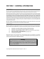
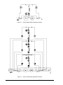
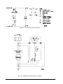
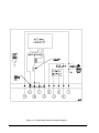
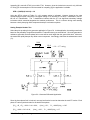
Typical application schemes are shown in Figures 1-1 and 1-2.
BE1-87G - General Information
1-1
Figure 1-1. Typical Single-Phase Application Scheme
Figure 1-2. Typical Three-Phase Application Scheme
1-2
BE1-87G - General Information
Variable Restraint Characteristic
At high current levels, the inevitable difference in the saturation characteristics between current transformers
indicates a need for a compensating decrease in relay sensitivity. The design of the BE1-87G provides a
restraint factor that is proportional to input current when the restraining current (I R) is greater than nominal
(five amperes for sensing input type one or one ampere for sensing input type two). The BE1-87G compares
the protected zone sensed input and output currents. The lesser of the two sensed current levels becomes
the restraining current. The difference between the two sensed currents (the operating current) is compared
to a reference established by the sensitivity setting, and adjusted by an amount proportional to the
restraining current. This makes the BE1-87G more sensitive to low current internal faults, and less sensitive
to external faults with high levels of through current.
When the restraining current is at nominal (five amperes for sensing input type one or one ampere for
sensing input type two) or less, the relay trips if the differential current exceeds the relay setting (I S). But
when the restraining current is greater than nominal, the overall sensitivity is a combination of the front panel
setting and the restraint factor.
Design Highlights
Some of the many advantages of the solid-state BE1-87G Variable Percentage Differential Relay are
summarized as follows.
Seven sensitivity levels on each of the two sensing input ranges. The seven levels allow
compensation for CT mismatch and provide the flexibility and adaptability necessary for many
special applications such as split winding generator protection.
Stabilizing reactor. Minimizes dissimilar performance of system CTs. Reactor can be located on
the back of the relay or remotely from the BE1-87G for flexibility of system installation.
Variable restraint. The variable restraint characteristic allows increased sensitivity to low current
internal faults while providing increased security against high levels of through current caused by
external faults.
Single- or three-phase availability. Either configuration is available in the Basler Electric S1 drawout
case.
High-Speed Operation. The BE1-87G operates in 30 milliseconds for fault levels of 10 times the
sensitivity setting. This high-speed operation minimizes potential damage to the protected
equipment. Response characteristics for sensing input ranges 1 and 2 are shown in Section 5,
Testing And Setting the relay.
MODEL AND STYLE NUMBER
The electrical characteristics and operational features included in a specific relay are defined by a
combination of letters and numbers which constitutes the device's style number. The style number together
with the model number describe the features and options in a particular device and appear on the front
panel, drawout cradle, and inside the case assembly. The model number BE1-87G designates the relay
as a Basler Electric Class 100, Variable Percentage Differential Relay.
Style Number Example
Figure 1-3 illustrates the style number identification chart with features and options for BE1-87G relays. For
example, if the style number were BE1-87G GlE AlJ AOCOF the device would have the following:
BE1-87G - General Information
1-3
BE1-87G
G
1
E
A1
J
A
0
C
0
F
Model Number
Three-phase sensing input
Sensing range switch selectable for 0.1, 0.15, 0.2, 0.4, 0.5, 0.8, or 1.6 A
Normally open output relay
Instantaneous timing
Operating power derived from 125 Vdc or 100/120 Vac
Internally operated targets (one per phase)
No option 1 available
Push-to-energize outputs (pushbuttons)
No auxiliary output contacts
Semi-flush mounting
Style Number Identification Chart
Figure 1-3 is the Style Number identification Chart for the BE1-87G Variable Percentage Differential relay.
Figure 1-3. Style Number Identification Chart
1-4
BE1-87G - General Information
SPECIFICATIONS
BE1-87G relays are available in single-phase and three-phase configurations, and with the following features
and capabilities.
Current Sensing Inputs
(5 Ampere)
(1 Ampere)
Current Sensing Burden
(5 Ampere)
(1 Ampere)
Stabilizing Reactor
I 2 t Rating
(5 Ampere)
(1 Ampere)
Pickup Control
(5 Ampere)
Nominally rated at 5 amperes, with a range of 45 to 65 hertz. Maximum
current per input: 10 amperes continuous, 250 amperes for 1 second.
Nominally rated at 1 ampere, with a range of 45 to 65 hertz. Maximum
current per input: 2 amperes continuous, 50 amperes for 1 second.
Burden is less than 0.05 ohms per input.
Burden is less than 0.25 ohms per input.
Refer to Section 4 for stabilizing reactor impedance characteristic curves.
65 amperes for 1 second at 70( C ambient, (I 2 t = 4225).
13 amperes for 1 second at 70( C ambient, (I 2 t = 4225).
A front panel control permits minimum differential (operate) currents to be
selected. This sensitivity is constant for restraint currents less than the
nominal current (5 or 1 amperes). Actual operating characteristics are
shown in graph format in Section 5, Testing And Setting the relay.
Minimum differential (operate) current = 0.1, 0.15, 0.2, 0.4, 0.5, 0.8, or 1.6
amperes. The ideal operating characteristic is approximated by the
following equations.
where
I R is the restraint current, defined as the lesser of the input currents.
I OP is the operate current
I S is the front panel setting
For I R 5 amperes: I OP = I S
For I R > 5 amperes: I OP = I S + 0.5(I R - 5)
(1 Ampere)
Minimum differential (operate) current = 0.02, 0.03, 0.04, 0.08, 0.10, 0.16,
or 0.32 ampere. The ideal operating characteristic is approximated by the
following equations.
For I R 1 ampere: I OP = I S
For I R > 1 ampere: I OP = I S + 0.5(I R - 1)
Pickup Accuracy
(5 Ampere)
For I R 5 amperes, ±5% of the operate pickup characteristic or 25
milliamperes whichever is greater. Actual operating characteristics are
shown in graph format in Section 5, Testing And Setting the relay.
For I R 5 amperes, up to a maximum of 20 amperes, ±8% of the operate
pickup characteristic or 150 milliamperes, whichever is greater. Actual
operating characteristics for pickup values between 5 and 20 amperes are
shown in graph format in Section 5, Testing And Setting the relay.
BE1-87G - General Information
1-5
Pickup Accuracy
(1 Ampere)
For I R 1 ampere, ±5% of the operate pickup characteristic or 25
milliamperes whichever is greater. Actual operating characteristics are
shown in graph format in Section 5, Testing And Setting the relay.
For I R 1 amperes, up to a maximum of 4 amperes, ±8% of the operate
pickup characteristic or 150 milliamperes, whichever is greater. Actual
operating characteristics for pickup values between 1 and 4 amperes are
shown in graph format in Section 5, Testing And Setting the relay.
Dropout
Greater than 90% of operate characteristic.
Timing
Less than 30 milliseconds at 10 times pickup setting; 70 milliseconds
maximum. See Section 5, Testing And Setting the relay, for the pickup
response timing curve.
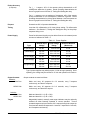
Power Supply
Power for the internal circuitry may be derived from ac or dc external power
sources as indicated in Table 1-1.
Table 1-1. Power Supplies
Type
Nominal Input
Voltage
K (Mid Range)
48 Vdc
24 to 60 Vdc
5.0 W
J (Mid Range)
125 Vdc
120 Vac
62 to 150 Vdc
90 to 132 Vac
5.5 W
14.5 VA
L (Low Range)+
24 Vdc
12 to 32 Vdc
5.5 W
Y (Mid Range)
48 Vdc
125 Vdc
24 to 60 Vdc
62 to 150 Vdc
5.5 W
6.0 W
Z (High Range)
250 Vdc
230 Vac
140 to 280 Vdc
190 to 270 Vac
7.0 W
20.0 VA
+
Output Contacts
Resistive:
120/240 Vac
125/250 Vdc
Inductive:
120/240 Vac,
125/250 Vdc
Targets
1-6
Input Voltage
Range
Burden at Nominal
(Maximum)
Type L power supplies may initially require 14 Vdc to begin operating. Once
operating, the voltage may be reduced to 12 Vdc and operation will continue.
Output contacts are rated as follows.
Make and carry 30 amperes for 0.2 seconds, carry 7 amperes
continuously, and break 7 amperes.
Make and carry 30 amperes for 0.2 seconds, carry 7 amperes
continuously, and break 0.3 ampere.
Make and break 0.1 A (L/R = 0.04).
Make and break 0.1 A (L/R = 0.04).
Magnetically latched, manually reset target indicators may be optionally
selected as either internally operated or current operated. Current
operated targets require a minimum of 0.2 ampere through the output trip
circuit and are rated at 30 amperes for 1 second, 7 amperes for 2 minutes,
and 3 amperes continuously.
BE1-87G - General Information
Isolation
In accordance with ANSI/IEEE C37.90, one minute dielectric (high
potential) tests as follows:
All circuits to ground:
Input to output circuits:
2121 Vdc
1500 Vac or 2121 Vdc
Surge Withstand Capability
Qualified to ANSI/IEEE C37.90.1-1989 Standard Surge Withstand
Capability (SWC) Tests for Protective Relays and Relay Systems.
Fast Transient
Qualified to ANSI/IEEE C37.90.1-1989.
Impulse Test
Qualified to IEC 255-5.
Radio Frequency
Interference (RFI)
Maintains proper operation when tested for interference in accordance
with IEEE C37.90.2, Trial-Use Standard Withstand Capability of Relay
systems to Radiated Electromagnetic Interference from Transceivers.
Temperature
Operating Range
-40(C (-40(F) to 70(C (158(F)
Recommended Storage Range
-65(C (-85(F) to 100(C (212(F).
Shock
15 g in each of three mutually perpendicular planes.
Vibration
2 g in each of three mutually perpendicular planes swept over the range
of 10 to 500 hertz for a total of six sweeps, 15 minutes each sweep.
Weight
3-phase: 19.2 pounds maximum.
1-phase: 14.3 pounds maximum.
Case Size
All units are supplied in an S1 size case.
BE1-87G - General Information
1-7
SECTION 2 • HUMAN MACHINE INTERFACE
(Controls And Indicators)
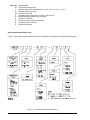
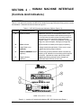
DESCRIPTION
Table 2-1 lists and briefly describes the BE1-87G Variable Percentage Differential Relay operator controls
and indicators. Reference the call-out letters to Figure 2-1.
Table 2-1. BE1-87G Controls and Indicators (Refer to Figure 2-1)
Locator
Control or Indicator
Function
A
Sensitivity Switch
Establishes reference for the operating current. It is a
seven position thumbwheel switch labeled A through G.
The chart below the switch relates the switch position to
the operating current required for tripping when the
restraint current is nominal (five amperes, sensing input
range one, and one ampere, sensing input range two).
B
Power Indicator
LED illuminates to indicate power supply is operating.
C
Target Reset Lever
(Optional)
Linkage extends through bottom of front cover to reset
magnetically latching target indicators.
D
PUSH-TO-ENERGIZE Switch
(Optional)
A momentary contact pushbutton switch accessible by
inserting a 1/8" diameter non-conducting rod through the
front panel. Operates the output and auxiliary relays.
E
Target Indicators
(Optional)
Magnetically latching indicators which indicate the
associated phase that has caused a trip.
NOTE: Above panel for 3L units only.
Figure 2-1. Location of Controls and Indicators, BE1-87G, Sensing Input Range 1
BE1-87G - Human Machine Interface (Controls And Indicators)
2-1
SECTION 3 • FUNCTIONAL DESCRIPTION
GENERAL
BE1-87G Variable Percentage Differential Relays are static devices that protect motors and generators by
providing an output signal when incoming current does not match outgoing current by a predetermined but
variable limit. The functional block diagram in Figure 3-1 illustrates the overall operation of the BE1-87G
Variable Percentage Differential Relay. Note that it may be configured to monitor either single-phase or threephase. Phases B and C, when present, are functionally identical to Phase A.
Figure 3-1. Functional Block Diagram
FUNCTIONAL DESCRIPTION
The following paragraphs describe the Relay circuit functions illustrated in Figure 3-1.
Current Transformers
Two standard system CTs with secondary windings to match sensing input range one or range two (five ampere
BE1-87G - Functional Description
3-1
and one ampere nominal), one transformer on each side of the protected machine, supply sensing current for
each monitored phase. The sensing currents are applied to the respective input transformers of the relay which
provide system isolation and determine the differential and sum currents. These CTs are gapped to withstand
DC offset.
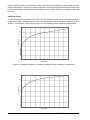
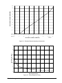
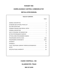
Stabilizing Reactor
To minimize dissimilar performance of the system CTs, the stabilizing reactor acts as a stabilizing impedance
during external faults. Stabilizing reactors are current rated based on time and ambient temperature (refer to
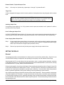
Section 1, Specifications). See Figures 3-2 and 3-3 for the stabilizing reactor impedance characteristics.
35
30
VOLTAGE(VOLTS)
25
20
15
10
5
0
0
1
2
3
4
5
6
7
8
9
10
CURRENT(AMPS)
Figure 3-2. Sensing Input Range 1 (5 Ampere), Stabilizing Reactor Impedance Characteristics
30
25
VOLTAGE(VOLTS)
20
15
10
5
0
0
0.2
0.4
0.6
0.8
1
1.2
1.4
1.6
1.8
2
CURRENT(AMPS)
3-2
BE1-87G - Functional Description
Figure 3-3. Sensing Input Range 2 (1 Ampere),Stabilizing Reactor Impedance Characteristics
Bandpass Filters
Outputs from the relay transformers are filtered to eliminate the third harmonic and to minimize the effect of DC
offset caused by CT saturation (as may occur during synchronization or asymmetrical faults).
The output of the difference bandpass filter is applied to a full wave rectifier. The rectifier scales the differential
and applies the output to the comparator as the operating current (I OP ) signal .
The output of the sum bandpass filter is also applied to a full wave rectifier. The scaled sum of the two inputs
represents the restraint current (I R ). The restraint current is scaled for a 50% slope above nominal input current
(five amperes input range one and one ampere input range two).
Comparator
The comparator provides the variable percentage characteristic of the relay as follows:
When I R is less than nominal (five amperes input range one and one ampere input range two), the
comparator provides an output signal whenever the operate current (I OP ) exceeds the front panel sensitivity setting I ( S ).
When I R is greater than nominal (five amperes input range one and one ampere input range two), the
front panel sensitivity threshold is increased by adding to it a scaled value representing 1/2 of I R minus
nominal (five amperes input range one and one ampere input range two).
Outputs
In the three-phase model, the outputs of the comparators are OR'd so that the coil of the output relay is
energized if the current difference of any monitored phase exceeds the variable percentage limit. When the
current difference falls below 90% of the variable percentage threshold, the output relay resets.
Targets (Optional)
If the relay is equipped with targets, the target associated with the phase or phases with excessive differential
current is tripped.
Depending on the style number (TARGET Option A or B), a unit may contain either internally operated or current
operated targets. Internally operated targets are actuated in conjunction with the output relay. Current operated
targets require a minimum of 0.2 ampere in the output circuit for actuation. Both types are magnetically latching
devices and must be manually reset by use of the reset lever.
Push-To-Energize (Optional)
The unit may be equipped (Option 2-C) with a momentary pushbutton that is accessible through the front panel.
To prevent accidental operation of this switch, it is recessed behind the front panel of the relay and is actuated
by inserting a thin non-conducting rod through an access hole in the panel. When pushed, the switch operates
the output relays and internally operated targets. Current operated targets will activate if the required 0.2
ampere of minimum current is present.
Power Supply Status Output (Optional)
The power supply status output relay (Option 3-6) has normally closed (NC) output contacts. This relay is
energized upon power-up and the NC contacts open. Normal relay operating voltage maintains the power
BE1-87G - Functional Description
3-3
supply status output relay continually energized and its output contacts open. If the power supply output voltage
falls below the requirements for proper operation, the power supply status output relay de-energizes, closing the
NC output contacts.
Power Supply
Basler Electric enhanced the power supply design for unit case relays. This new design created three, wide
range power supplies that replace the five previous power supplies. Style number identifiers for these power
supplies have not been changed so that customers may order the same style numbers that they ordered
previously. The first newly designed power supplies were installed in unit case relays with EIA date codes 9638
(third week of September 1996). Relays with a serial number that consists of one alpha character followed by
eight numerical characters also have the new wide range power supplies. A benefit of this new design increases
the power supply operating ranges such that the 48/125 volt selector is no longer necessary. Specific voltage
ranges for the three new power supplies and a cross reference to the style number identifiers are shown in the
following table.
Table 3-1. Wide Range Power Supply Voltage Ranges
Power Supply
Style Chart Identifier
Low Range
L
Mid Range
High Range
Nominal Voltage
Voltage Range
24 Vdc
12† to 32 Vdc
J, K, Y
48, 125 Vdc,
120 Vac
24 to 150 Vdc
90 to 132 Vac
Z
125, 250 Vdc,
120, 240 Vac
62 to 280 Vdc
90 to 270 Vac
† 14 Vdc required to start the power supply.
Relay operating power is developed by the wide range, isolated, low burden, flyback switching, solid state power
supply. Nominal +12 Vdc is delivered to the relay internal circuitry. Input (source voltage) for the power supply
is not polarity sensitive. A red LED turns ON to indicate that the power supply is functioning properly.
3-4
BE1-87G - Functional Description
SECTION 4 • INSTALLATION
GENERAL
When not shipped as part of a control or switchgear panel, the relays are shipped in sturdy cartons to prevent
damage during transit. Immediately upon receipt of a relay, check the model and style number against the
requisition and packing list to see that they agree. Visually inspect the relay for damage that may have occurred
during shipment. If there is evidence of damage, immediately file a claim with the carrier and notify the Regional
Sales Office, or contact the Sales Representative at Basler Electric, Highland, Illinois.
In the event the relay is not to be installed immediately, store the relay in its original shipping carton in a moisture
and dust free environment. When relay is to be placed in service, it is recommended that the operational test
procedure in Section 5, Testing And Setting, be performed prior to installation.
DIELECTRIC TEST
In accordance with IEC 255-5 and ANSI/IEEE C37.90-1989, one-minute dielectric (high potential) tests may be
performed as follows:
All circuits to ground:
Input to output circuits:
2828 Vdc
2000 Vac or 2828 Vdc
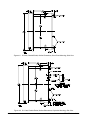
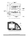
MOUNTING
Relay
Because the relay is of solid state design, it
does not have to be mounted vertically. Any
convenient mounting angle may be chosen.
Relay outline dimensions and panel drilling
diagrams are shown in Figures 4-1 through 47. Numbers in parentheses indicate metric
dimensions (millimeters). All other dimensions
are in inches.
Figure 4-1. S1 Case, Outline Dimensions, Front View
BE1-87B - Installation
4-1
Figure 4-2. S1 Case, Double-Ended, Outline Dimensions, Semi-Flush Mounting, Side View
Figure 4-3. S1 Case, Double-Ended, Outline Dimensions, Projection Mounting, Side View
4-2
BE1-87B - Installation
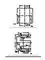
Figure 4-4. S1 Case, Double-Ended, Panel Drilling Diagram, Semi-Flush Mounting
Figure 4-5. S1 Case, Double-Ended, Panel Drilling Diagram, Projection Mounting, Rear View
BE1-87B - Installation
4-3
Stabilizing Reactor
The stabilizing reactor for a three-phase relay is mounted on the rear of the relay. For projection mounting
or convenience, the stabilizing reactor can be removed and relocated. Rewire in accordance with the
procedures and illustrations in this section. To remove the stabilizing reactor, remove four screws holding
the reactor to the mounting plate. To remove the mounting plate, remove two five-sixteenths by eighteen,
hex head bolts. The stabilizing reactor outline dimensions and panel drilling diagrams are shown in
Figures 4-6 and 4-7.
Figure 4-6. Outline Dimensions for External Reactor Chassis 9 1708 18 100
4-4
BE1-87B - Installation
Figure 4-7. S1 Case And Reactor, Outline Dimensions (Semi-Flush Mounting)
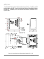
CONNECTIONS
Incorrect wiring may result in damage to the relay. Be sure to check model and style number against the
options listed in the Style Number Identification Chart before connecting and energizing a particular relay.
WARNING
Relays manufactured prior to July 22, 1991 (EIA date code symbol 9129 and previous)
do NOT have case jumpers between terminals 7 and 8 (single phase units). This also
applies to three phase relays terminals 7 and 8, terminals 13 and 14, and terminals 17
and 18. Exercise CAUTION when grounding or testing current transformer circuits
connected to these terminals.
NOTE
Be sure the relay case is hard-wired to earth ground with no smaller than 12 AWG copper
wire attached to the ground terminal on the rear of the relay case. When the relay is
configured in a system with other protective devices, it is recommended to use a
separate lead to the ground bus from each relay.
Except as noted above, connections should be made with minimum wire size of 14 AWG. Typical dc control
connections are shown in Figure 4-8. Sensing input connections are shown in Figures 4-9 and 4-10.
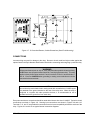
Terminals 7, 13, and 17 are provided for convenience and to insure compatibility with earlier versions of the
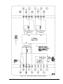
relay. Figures 4-11 and 4-12 are typical internal connection diagrams.
BE1-87B - Installation
4-5
Figure 4-8. Typical DC Control Connections
Figure 4-9. Single-Phase Sensing Input Connections
4-6
BE1-87B - Installation
Figure 4-10. Three-Phase Sensing Input Connection
BE1-87B - Installation
4-7
Figure 4-11. Single-Phase Internal Connection Diagram
4-8
BE1-87B - Installation
Figure 4-12. Three-Phase Internal Connection Diagram
BE1-87B - Installation
4-9
SECTION 5 • TESTING AND SETTING
GENERAL
Proper operation of the relay may be confirmed by performing the operational test procedures in this Section.
In the event the relay is not to be installed immediately, store the relay in its original shipping carton in a moisture
and dust free environment.
RELAY OPERATING PRECAUTIONS
Before installation or operation of the relay, note the following precautions:
1.
A minimum of 0.2 ampere in the output circuit is required to ensure operation of current
operated targets.
2.
The relay is a solid-state device. If a wiring insulation test is required, remove the connection
plugs and withdraw the cradle from its case.
CAUTION
To avoid false tripping on three phase units, upper connection plug must be in place
prior to inserting or removing lower connection plug.
3.
When the connection plugs are removed the relay is disconnected from the operating circuit and
will not provide system protection. Always be sure that external operating (monitored)
conditions are stable before removing a relay for inspection, test, or service.
4.
Be sure the relay case is hard wired to earth ground using the ground terminal on the rear of
the unit. It is recommended to use a separate ground lead to the ground bus for each relay.
DIELECTRIC TEST
In accordance with and ANSI/IEEE C37.90, one minute dielectric (high potential) tests as follows.
All circuits to ground:
Input to output circuits:
2121 Vdc
1500 Vac or 2121 Vdc
EQUIPMENT REQUIRED
Because of the speed and sensitivity of this relay, it is necessary that the accuracy and stability of the test
equipment be appropriate to test the sensitivity switch settings. For example, this switch at the most sensitive
setting (0.1 ampere) is monitoring a current difference that is only 1% for a sensing input of 10 amperes.
Two Multi-Amp SSR-78, or one Doble F2500, or suitable substitute
Digital voltmeter accurate to within 1% or better
Digital ammeter accurate to within 1% or better
Variable AC/DC ()-250 V) power supply (operating power input)
DC power supply (for current operated targets)
BE1-87G - Testing And Setting
5-1
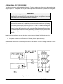
OPERATIONAL TEST PROCEDURE
The following procedure verifies operation of the relay. Terminal numbers are referenced to the operational test
setup in Figure 5-1. Three-phase units may be tested one phase at a time because all phases are OR'd together
at the output.
WARNING
During testing, do NOT apply or generate continuous operate current greater than three
amperes. If the operate current is greater than three amperes, a temperature increase
in the reactor may result and cause insulation breakdown.
NOTE
Because of the reactance of the stabilizing reactors, the burden may be too high for large
values of operate current with solid state test sets. Stabilizing reactor L1 may be shorted
out in single-phase relays by placing a jumper on TP-1 and TP-2 on the lower magnetics
shield board. The jumper should be capable of carrying five amperes of operate current.
Figure 5-2 shows the location of the lower magnetics shield board assembly and Figure
5-3 shows test point locations. In three-phase relays, current sources may be connected
directly to the upper and lower terminals (6-9 and 12-19) to bypass the external reactor
chassis.
Restraint current supplied to any one relay input must not exceed either of the following conditions.
10 amperes continuous or 250 amperes for 1 second (sensing input range one)
2 amperes continuous or 50 amperes for 1 second (sensing input range two)
Whenever this current level is exceeded, provisions must be made to cut off the sensing current as the relay
trips.
Figure 5-1. Operational Test Setup
5-2
BE1-87G - Testing And Setting
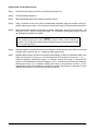
Figure 5-2. Location of Assemblies (Single Phase Only)
NON-COMPONENT SIDE OF LOWER MAGNETICS/SHIELD BOARD
Figure 5-3. TP-1 and TP-2 on Single Phase Relays
BE1-87G - Testing And Setting
5-3
Single-Phase Trip And Dropout Test
Step 1.
Connect the test setup for phase A in accordance with Figure 5-1.
Step 2.
Set the sensitivity switch to A.
Step 3.
Apply appropriate power input voltage to terminals 3 and 4.
Step 4.
Using a regulated current source that is independently adjustable, apply the restraint current (0.1
ampere, sensing input range 1 or 0.02 ampere, sensing input range 2) to phase A terminals 6 and 9.
Step 5.
Slowly increase the operate current source to phase A terminals 6 and 8 until the relay trips. Trip
should occur at (0.1 ampere, sensing input range 1 or 0.02 ampere, sensing input range 2), ±(5% or
25 milliamperes), whichever is greater.
NOTE
Output contacts may be NC or NO, depending on style of relay. Check continuity at
terminals 1 and 10 with relay tripped and not tripped to assure correct response for the
type of contacts specified.
Step 6.
Slowly decrease the operate current source until dropout. Reset must occur at a value of current that
is greater than or equal to 90% of I s (sensitivity switch setting value).
Step 7.
Repeat steps 2 through 6 for the other sensitivity switch settings. If desired, a sufficient number of trip
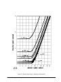
points may be taken to verify any or all of the performance curves shown in Figure 5-4. For I R nominal (5 amperes, sensing input range 1 or 1 ampere, sensing input range 2), the tolerance is
±(0.05 I OP or 25 milliamperes, whichever is greater.) For I R nominal up to a maximum of 20 amperes
(sensing input range 1) or 4 amperes (sensing input range 2), the tolerance is ±0.08 I OP on the
characteristic curve or 150 milliamperes, whichever is greater. See Figures 5-4 through 5-7 for the
operating characteristic curves and trip response timing curve.
5-4
BE1-87G - Testing And Setting
Figure 5-4. Sensing Input Range 1, Operating Characteristics
BE1-87G - Testing And Setting
5-5
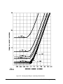
Figure 5-5. Sensing Input Range 2, Operating Characteristics
5-6
BE1-87G - Testing And Setting
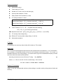
20
RESTRAINT CURRENT (AMPERES)
18
16
14
12
10
8
6
4
2
0
Range 1
0
5
10
15
20
25
30
35
40
Range 2
0
1
2
3
4
5
6
7
8
D2354-14
04-30-96
RESTRAINT CURRENT (AMPERES)
Figure 5-6. Extended Restraint Operating Characteristic
45
RESPONSE TIME (MSEC)
40
35
30
25
20
15
0
10
20
30
40
50
60
70
80
90
MULTIPLES OF PICKUP
Figure 5-7. Pickup Response Timing
BE1-87G - Testing And Setting
5-7
Phases B And C, Trip And Dropout Test
Step 1.
If the relay is a 3-phase relay, repeat steps 1 through 7 for phases B and C.
Target Test
If relay is equipped with targets, check for correct operation of each phase when relay is tripped, and for manual
reset.
NOTE
If option B (current operated) targets are specified, the target is only operable when a
minimum of 0.2 ampere is present in the output circuit (terminals 1 and 10).
Auxiliary Output Test
If an Auxiliary output (Option 3-2 or 3-3) is present, check outputs at terminals 2 and 5 (either NC or NO as
specified) when relay is tripped.
Push To Energize Output Test
If a PUSH TO ENERGIZE switch (Option 2-C) is present, verify correct operation by depressing the switch and
observing that the output and auxiliary relays cycle (terminals 1 and 10 and terminals 2 and 5 respectively.)
Power Supply Status Output Test
Step 1.
If power supply status output (Option 3-6) is present, verify correct operation by applying appropriate
voltage to the power input, placing the unit in a powered-up condition, verifying that the power supply
status output contacts are energized open (terminals 2 and 5).
Step 2.
Remove input power and verify that the power supply status output contacts close.
SETTING THE RELAY
General
This paragraph provides recommendations for selecting the current sensitivity switch setting. Figures 5-4 and
5-5 show how this setting corresponds to the operating current pickup over the restraint current range.
Assuming that the CTs on both sides of the zone (generator, motor or reactor) perform identically, operating
current will be equal to zero. The sensitivity setting serves to accommodate dissimilar CT performance, resulting
from differences in CT quality, burden, and core remanence.
During normal operation, the pickup on the flat part of the operating characteristics (refer to Figures 5-4 and 5-5)
must exceed the difference in steady-state CT errors. The relay must also override the error differences in the
presence of dc components developed by external faults or switching. Currents will be offset during external
faults on generator applications, during motor starting, and during switching of shunt reactors.
Out-of-phase synchronizing of machines will also produce offset components. These so-called dc components
will produce significant CT saturation. For high-current faults, the relay relies on the 50% slope characteristic
to override large operating currents. Significant operating current can also be developed at restraint levels that
fall on the flat part of the characteristic if the offset component persists. The sensitivity setting needs to be above
this operating current.
5-8
BE1-87G - Testing And Setting
Terms for Calculations
I"d
Subtransient current
N
Total number of CT turns
Na
Number of CT turns in use (for multi-ratio type)
Rl
One-way lead resistance, in ohms
Rr
Relay restraint circuit resistance, in ohms
Rw
CT winding resistance, in ohms.
NOTE
Sensing Input Range 1: If R w is unknown, assume R w = 0.003 * N a
Sensing Input Range 2: If R w is unknown, assume R w = 0.01 * N a
Rt
Total CT burden = R l + R r + R w
(for phase faults and switching)
= 2R l + 2R r + R w (for external ground faults)
SFR Saturation factor ratio = [(Vce) 1/(Vce) 2]*[(R t) 2/(R t) 1] (If SFR is < 1, use 1/SFR)
Vc
CT accuracy-class voltage rating
Vce Effective CT accuracy-class voltage rating = Vc (N a/N)
X"d
Subtransient reactance
CT Quality
CTs should have an accuracy class of either C20 or better or T20 or better.
Burden Limit
The CTs should be operating below the knee point under symmetrical current conditions --i.e. no "ac saturation".
For a generator, ac saturation should not occur for the maximum external fault current. For a motor, ac
saturation should not occur during starting. For a shunt reactor, high current fundamental-frequency currents
won't flow unless the reactor becomes faulted.
Assuming a maximum current of 20 times CT rating:
R t < 0.007Vce
(1)
where V knee = 70% of Vce and 20 X 5 A nominal rating = 100 A so that
R t = V knee / I max = 0.7 Vce/ 100 A = 0.007 Vce
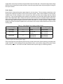
Relative CT Performance
Table 5-1 lists the recommended minimum pickup settings to provide security during external faults and
switching.
BE1-87G - Testing And Setting
5-9
Table 5-1. Recommended Pickup Settings
Vce
(Lower Value)
SFR
1
1.5
2
3
4
20
0.2
0.4
0.5
0.8
1.6
50
0.2
0.4
0.4
0.5
0.8
100
0.2
0.2
0.4
0.4
0.5
200
0.1
0.1
0.2
0.4
0.5
>200
0.1
0.1
0.2
0.4
0.5
Note: Use next higher setting if CTs are a mix of C classification and T classification.
The saturation factor ratio, SFR, represents an index of the relative performance of the two sets of CTs. This
performance is a function of the relative quality of the CTs (Vce), the relative burdens (R t), and neglecting the
remanence. If SFR is < 1, then use 1/SFR for SFR.
Setting Example Number One
Select the pick-up setting for the motor application in Figure 5-8. In this application, the settings need to be
based on the probability of significant dissimilar CT saturation due to the very slowly decaying dc component
of the starting current. Since the motor is not grounded, no ground current can flow during starting of an
unfaulted motor. Therefore, one-way lead burden is used to determine the total CT burden. Each phase CT
carries just the burden for the lead for that phase.
Figure 5-8. Motor Differential Application
(R t) 1 = R l + R w = 0.22 + 0.14 = 0.36 ;
(R t) 2 = 0.09 + 0.10 = 0.19 ;
5-10
(Vce) 1 = 50 ;
(Vce) 2 = 100 ;
R t < 0.007(Vce) 1 = 0.35
R t < 0.007(Vce) 2 = 0.7
BE1-87G - Testing And Setting
Inequality (1) is met with CT #2, but not with CT #1. However, since the locked rotor current is only 4.8 times
CT rating [vs. the assumption of 20 times rated for inequality (1)], the application is suitable.
SFR = (100/50)*(0.36/0.19) = 3.8
Using the SFR 4 column of Table 5-1, a 0.8 ampere setting is indicated. However, based on the note
accompanying this table, choose the next higher setting of 1.6, because CT #1 has a T classification, and CT
#2 has a C classification. The T classification indicates that the CT has significant secondary leakage
inductance which somewhat degrades the transient performance. This is a concern during motor starting
because a slowly decaying offset component develops in at least one phase.
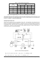
Setting Example Number Two
Select the pick-up setting for the generator application in Figure 5-9. In this application, the settings need to be
based on the probability of significant dissimilar CT saturation during an external fault. Since the generator is
resistance grounded, the three-phase fault current will be much larger than the ground fault level. Moreover,
the resistor will rapidly dampen any offset-current component. Accordingly, determine the subtransient current
(I"d ).
1000
4.16× 3
0.15×200
I d 138.8
4.6 × CT rating
30
Figure 5-9. Generator Differential Application
Since the three-phase fault is involved, one-way lead burden is used to determine the total CT burden. Each
phase CT carries just the burden for the lead for that phase.
(R t) 1 = R l + R w = 0.22 + 0.14 = 0.36 ;
(R t) 2 = 0.09 + 0.10 = 0.19 ;
BE1-87G - Testing And Setting
(Vce) 1 = 50 ;
(Vce) 2 = 100 ;
R t < 0.007(Vce) 1 = 0.35
R t < 0.007(Vce) 2 = 0.7
5-11
Inequality (1) is met with CT #2, but not with CT #1. However, since the maximum external fault current is only
4.6 times CT rating [vs. the assumption of 20 times rated for inequality (1)], the application is suitable.
SFR = (100/50)*(0.36/0.19) = 3.8
Using the SFR 4 column of Table 5-1, a 0.8 ampere setting is indicated. However, based on the note
accompanying this table, choose the next higher setting of 1.6, because CT #1 has a T classification, and CT
#2 has a C classification. The T classification indicates that the CT has significant secondary leakage
inductance which somewhat degrades the transient performance. This is a concern during motor starting
because a slowly decaying offset component develops in at least one phase.
5-12
BE1-87G - Testing And Setting
SECTION 6 • MAINTENANCE
GENERAL
BE1-87G Variable Percentage Differential Relays require no preventive maintenance other than a periodic
operational test (refer to Section 5 for the operational test procedures). If factory repair is desired, contact the
Customer Service Department of the Power Systems Group, Basler Electric, for a return authorization number
prior to shipping.
IN-HOUSE REPAIR
In-house replacement of individual components may be difficult and should not be attempted unless appropriate
equipment and qualified personnel are available.
CAUTION
Substitution of printed circuit boards or individual components does not necessarily mean
the relay will operate properly. Always test the relay before placing it in operation.
Where special components are involved, Basler Electric part numbers may be obtained from the number
stamped on the component or assembly, the schematic, or parts list. These parts may be ordered directly from
Basler Electric. When complete boards or assemblies are needed, the following information is required.
1. Relay model and style number
2. Relay serial number
3. Board or assembly
a) Part number
b) Serial number
c) Revision letter
4. The name of the board or assembly.
STORAGE
This protective relay contains aluminum electrolytic capacitors which generally have a life expectancy in excess
of 10 years at storage temperatures less than 40C. Typically, the life expectancy of the capacitor is cut in half
for every 10C rise in temperature. Storage life can be extended if, at one-year intervals, power is applied to
the relay for a period of thirty minutes.
BE1-87G - Maintenance
6-1
SECTION 7 • MANUAL CHANGE INFORMATION
SUMMARY AND CROSS REFERENCE GUIDE
This section contains information concerning the previous editions of the manual. The substantive changes
to date are summarized in Table 7-1.
Table 7-1. BE1-87G Changes
Revision
Summary Of Changes
ECA/ECO/Date
A
Added qualifications to specifications listing, revised isolation test and
dielectric test.
05-12-86/7820
B
Grammatical changes to specifications, changed comparator
functional description and operational test procedure.
10-07-86/8199
C
Added Power Supply Status Output Option 3-6
03-13-87/8485
D
Physically removed Power ON/OFF switch and added stabilizing
reactor. Added illustrations for typical connections, sensing input
connections, test setup, extended operational characteristics, and
pickup response timing. Added table for current sensing burden and
functional description of stabilizing reactor, setting the relay, and
setting the relay example.
03-0691/11227
E
Changed Figure 1-1 and 1-2, and added Warning pages 1-1 and 4-2.
07-1791/12091
F
Changed pickup accuracy for I R > 5 A from 30 A, ±5% to 20 A, ±8% of
the operate pickup characteristic or 150 mA, whichever is greater.
07-3091/12100
G
Added I 2 t rating of Stabilizing Reactor and new Figure 4-1, Stabilizing
Reactor Impedance Characteristics.
10-1791/12223
H
Added sensing input range 2 (one ampere nominal) to the available
models. Changed high speed operation from 20 milliseconds to 30
milliseconds. Changed all connection diagrams to include ground
connections where applicable. Added internal connection diagrams.
Corrected Table 1-1 Clarified Setting Example for motor differential
application, and added Setting Example Number Two, generator
differential application. Divided Section 4 into two sections. The new
Section 5, is Testing And Setting the relay.
05-0396/15555
J
Reformatted manual to current standards. Page 1-2, corrected Figure
1-2. Page 1-4, last paragraph, changed “Terminals 7, 13, and 14 are
provided for convenience . . .” to “Terminals 7, 13, and 17 are provided
for convenience . . .”. Corrected Figures 4-11 and 4-12. Updated this
section to show changes.
BE1-87G - Manual Change Information
05-12-99/4392
7-1