1
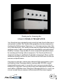
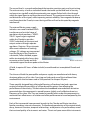
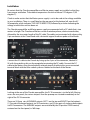
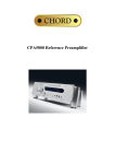
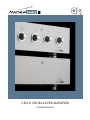
Cello Chorale preamplifier
Owners manual
Thank you for choosing the
Cello Chorale preamplifier
Your Chorale has been individually made, entirely by hand, from the finest parts
and materials available. The Chorale utilizes proprietary circuitry and processes,
developed by Matthew James’ Showroom, L.L.C., that represent true state of the
art in audio electronics. The Chorale contains the most recent thinking in analog
interface circuitry. It offers sonic performance and reliability, and a great deal of
flexibility. It accepts a large number of sources and provides optimized outputs
for recording and listening without compromise. The Chorale and Master are
designed to perform to specification for decades of enjoyment. Please read this
information carefully, and care for your Chorale so that it will retain its value, appearance, and performance.
If you have any questions, contact your authorized Cello representative, or contact Matthew James’ Showroom directly, via phone (860 349-5999) or email
([email protected]). It is our wish to assist you in any way possible to
facilitate your enjoyment. These are the private, home office phone number and
email address of Matthew James’ Showroom’s Managing Partner. As a result, you
can rest assured that your concerns will be treated with the utmost urgency.
WARNING: TO REDUCE THE RISK OF FIRE OR ELECTRIC SHOCK,
DO NOT EXPOSE THIS COMPONENT
TO RAIN OR MOISTURE.
RISK OF ELECTRICAL SHOCK
DO NOT OPEN
CAUTION:
TO REDUCE THE RISK OF ELECTRICAL SHOCK,
DO NOT REMOVE COVER.
NO USER-SERVICEABLE PARTS INSIDE.
REFER SERVICING TO QUALIFIED PERSONNEL.
Marking by the “CE” symbol (shown left) indicates compliance of this
device with the EMC (Electromagnetic Compatibility) and LVD (Low Voltage
Directive) standards of the European Community.
Please read all instructions and precautions carefully and completely
before operating your Cello Encore power amplifier.
1 ALWAYS disconnect the entire system from the AC mains before connecting or disconnecting
any cables, or when cleaning any component.
2 AC extension cords are not recommended for use with this product.
3 NEVER use flammable or combustible chemicals for cleaning audio components.
4 NEVER operate this product with any covers removed.
5 NEVER wet the inside of this product with any liquid, or pour/spill liquids directly onto this unit.
6 NEVER block airflow through ventilation slots.
7 NEVER bypass any fuse or replace any fuse with a value or type other than those specified.
8 NEVER attempt to repair this product. If a problem occurs, contact your Cello retailer.
9 NEVER expose this product to extremely high or low temperatures.
10 ALWAYS unplug sensitive electronic equipment during lightning storms or if the unit
will not be used for a prolonged period.
Product Concept and Description
In the 17th and 18th centuries, Italian master instrument makers developed and virtually
perfected what we regard today as the modern string instruments. The name, Cello,
embodies the spirit and concept of our products. We are dedicated to furthering the art of
music reproduction by designing and building equipment of only the very highest quality,
in limited quantities, by hand. Although we are developing and utilizing new technology,
Matthew James is really continuing a very old, traditional approach used by artisans for
hundreds of years. The justification for a great music system is the same as for a great
instrument: it makes possible a musical experience that cannot be duplicated by lesser
means.
This philosophy is evidenced
completely in the Chorale preamp and
Master power supply. They have been
designed to provide sonic quality,
consistent performance and reliability.
The Chorale preamplifier contains ten
precision audio amplifiers and four
power supply regulators to provide
the ideal analog interface for each
source component’s signal at the input.
It converts the input signal to a high
current, precision output for recording
or listening, with an ideal complement
of circuits and parts for those tasks.
Chorale Preamplifier inside chasis
In the Chorale and Master, low noise, extremely stable parts are used throughout for
highest clarity and maximum resolution. Beyond unsurpassed performance, we demand
reliable implementation and longevity from individual component parts. Following their
initial selection, we subject these parts to rigorous performance and reliability tests before
they are assembled into the components. All printed circuit boards use traces that are
drawn by hand, all parts are inserted into the board by hand, and individually soldered
to the boards by hand, as each of these provide tremendously improved reliability and
absolute maximization of performance. All internal signal cabling is hand-made from solid
silver, and is shielded and grounded with extraordinary care.
The Chorale preamplifier is built on three levels of circuit boards. The first level is a
motherboard that contains the ground and power supply routing. Extensive ground plane
techniques minimize interference from radiated energies. Large printed circuit paths for
DC power reduce detrimental voltage drops caused by resistance and inductance.
The second level is a second motherboard that contains precision parts and circuit wiring.
The active circuitry is built on individual boards that make up the third level of circuitry
and mount on standoffs made from extremely pure copper flashed with silver through
which the signal flows to and from the various boards. This practice minimizes any losses
and distortions of the signal, while improving contact reliability. Non-magnetic hardware,
used throughout the Chorale, insures that signal flow will not be disrupted by magnetic
interference.
The external Master power supply
includes a mu-metal shielded 350VA
transformer and an initial stage of
regulation which produces + 30VDC.
The DC signal is again regulated
within the Chorale to provide +
25VDC individually to the input and
output sections through separate
regulators. Precision 10 turn trimpots
allow exact calibration of tracking
voltages. DC voltages are transported
from the Master to the Chorale via
substantial, Teflon shielded, copper
cables terminated with a heavy duty
connector at the Chorale and with
substantial copper/rhodium spades at the Master.
Master inside chasis
All told, it requires 85 hours of labor to build, assemble and test a completed Chorale and
Master.
The chasses of both the preamplifier and power supply are manufactured with heavy
aluminum plates on all six sides. Front, top and side panels are of the traditional clear
anodized finish that has been used in Cello products for the past 20 years.
Three specially designed feet, utilizing ball bearings of hardened steel and a precision
coating, eliminate the possibility of surface-borne disruptions from affecting the
performance of the circuitry. The feet reduce the broadband intermodulation distortion
generated when the component is moved however slightly, and is effective down to a
Encore
insidepoints
chasis under the components to
frequency of less than .5Hz. They are located at
specific
maximize their effectiveness at isolation and allow performance to be unhampered by the
environment.
Each of the incremental improvements brought to the Chorale and Master transform
familiar recordings into new discoveries. The unaltered reproduction of the original attack,
decay, harmonic structure, temporal relationships, and dynamics of a performance, reveal
the true tonal quality of instruments and voices. The air and space around the instruments
are preserved and the exact location of every performer is discernable. Even the most
complex musical passages are reproduced effortlessly, retaining the most delicate nuances.
This level of performance is only attained by combining advanced technology with a purist’s
approach to design and execution.
In each completed product, superior quality has been assured, first by meticulous
planning and design, next by the choice of the finest materials, then by highly skilled hand
construction of each unit, and finally by exhaustive testing and sonic evaluation.
Music, for thousands of years, has been the inspired expression of human emotion and
possibility. Over the centuries gifted artisans like Amati and Stradivari have enabled
composers to more clearly articulate their vision through the perfection of musical
instruments. The dedicated master musician insists on using an instrument made by a great
craftsman. To reproduce music faithfully and exquisitely requires nothing less than the very
best audio equipment. Each product from Matthew James is a blend of proven principles
from the past and new technological understandings. Something new is added only if it
proves meaningful in performance.
Unpacking
The packing box for the Chorale preamplifier should arrive in good condition. Please
inspect for damage to the carton, although this is unlikely due to the strength of the carton
construction. Open the packing carefully and save all foam pieces and boxes for re-use in
the event the Chorale or Master needs to be shipped in the future. Should the box become
lost, please contact your dealer for replacement carton and packing material.
Each Chorale carton should contain:
(1) one Cello Chorale preamplifier
(1) one DC cable with (5) five color coded connectors
(1) one owner’s information sheet.
An important part of the Cello philosophy is found in the physical separation of the power
supply from the active circuitry of either the preamplifier or the amplifier. The external
Master power supply includes a mu-metal shielded transformer and power supply
regulation. DC voltages are transported from the Master to the Chorale via substantial,
Teflon shielded, copper cables terminated with a heavy duty connector at the Chorale and
with substantial copper/rhodium spades at the Master.
Each Master carton should contain:
(1) one Cello Master power supply
(1) one AC cable.
Installation
Be certain that the Chorale preamplifier and Master power supply are installed so that they
have proper ventilation. The ambient temperature should not exceed 122 degrees F (50
degrees C).
Check to make certain that the Master power supply is set to be used at the voltage available
in your installation. There is a small label on the rear panel, at the bottom left, near the AC
IN receptacle, which indicates THIS UNIT IS WIRED FOR, followed by a sticker indicating the
voltage at which the unit has been set.
The Chorale preamplifier and Master power supply are connected with a DC cable that is two
meters in length. The Chorale and Master can be situated anywhere, relative to each other,
allowed by the two meter length of the DC cable. The cables are terminated with a heavy duty,
5 pin connector at the Chorale and with substantial copper/rhodium spades at the Master.
Connect the DC cable to the Chorale by lining up the 5 pins of the connector, labeled DC
IN, with the matching slots on the receptacle terminating the DC cable. Connect the DC
cable to the Master using the individually colored strands of cable to the screw-connected
terminal block with the color coded system as labeled on the back of the Master.
Looking at the rear of the Chorale preamplifier, the DC IN connector is to the far left. Moving
across the rear panel, the various outputs from the preamp are situated immediately to the
right of the DC IN connector.
There are (3) three sets of VARIABLE outputs (LEFT L on the top and RIGHT R on the bottom):
(1) One pair of balanced outputs via XLR connectors, and (2) two pairs of single-ended outputs
via RCA connectors. The VARIABLE outputs are controlled by the 59-position LEVEL control,
centered on the front panel, in 1dB steps.
The balanced output contains four individual, discrete amplifiers for the plus and minus
signals for each channel, providing Class A, symmetrical output to drive power amplifiers
with balanced inputs.
There are also two pairs of fixed outputs, both via RCA connectors. These can be connected
to the input of a recording device, or as an input to an audio processor, or to another
system.
Moving to the right side of the rear panel, there are the (4) four line level inputs, the
balanced input and the phono input and ground. Connect the source components to the
appropriate inputs on the preamplifier.
Connect the AC line cord from the IEC connector on the rear of the Master power supply to
the power outlet in your home.
Push the rear panel circuit breaker power button to turn the unit on. Your Chorale and
Master should now be functioning and the LED on the front panels should be red in color.
Operation
Looking across the face of the Chorale there are five switches, all controlled by knobs that
are hand milled from solid rods of aluminum and specially processed to offer operational
ease and enduring cosmetic appearance. As a final touch, all nomenclature is laser
engraved for elegance and longevity, imparting a level of craftsmanship reflective of every
other aspect of the product.
These knobs can rather easily displace the set screw which holds them in the correct
position relative to the shaft and the rest of the switch controlled. When adjusting the
INPUT, MONITOR, +dBL and +dBR controls, go slowly and definitively from position to
position when making a change to any of these switches.
LEVEL:
Centered on the face plate is the output level control. The output level is at its lowest position,
no variable output, when the indicator line is centered at the bottom of the knob. Output level is
variable between lower than -40dB of the source signal at the softest level and greater than +10dB
of the source signal at the loudest level.
Only the highest quality parts are used throughout the Chorale preamplifier and it contains
many parts not found in any other preamplifier on the market. Sometimes this has required us
to invent a part that does not have an equal otherwise. For more than 25 years, the 59 position
Cello volume control has set the standard for sonic excellence, reliability, and precision tracking.
Matthew James’ Showroom has changed the contact material of the wiper in this control from
what was used previously to a silver alloy that contains 10% gold and 10% platinum developed for
guidance systems for military hardware and satellite communications. Its resistance to corrosion
and tarnish made it attractive to us and it is guaranteed for 50 years of continual service with stable
contact resistance for low noise. The latest generation of this continues to set the standard for sonic
excellence, reliability, and precision tracking as it has for more than 25 years. Remote control of any
kind diminished performance and so could not be included.
This decision, freeing us from consideration of remote control, in turn led to our being able to
consider the large, hand soldered rotary switches that are used for input selection and monitoring
functions available on the left side of the faceplate, and for the individual balance/gain controls
available on the right side of the faceplate.
These switches offer superior performance and reliability through positive indexing and electrical
contact systems. While other types of switches allow for sources to be selected and volume to be
controlled via remote control, none of these offer the sonic excellence of the switches chosen.
Again, any convenience, which detracted from sonic performance, was not considered for inclusion
in the Chorale.
INPUT:
The control that is farthest left is the INPUT selector. The Chorale has a total of six inputs including
phono (labeled P), a balanced line input (B), and four single-ended line inputs (1, 2, 3, 4).
P (PHONO): P selects the phono input to which the output from a cartridge/tonearm/turntable
should be connected. Within the Chorale preamplifier the gain and input impedance of the phono
section are programmable to accommodate any cartridge.
This preamplifier has been set to 60dB of gain with 50kOhms / 220pf loading in the phono stage.
Instructions for making changes to these settings are contained at the end of this Owner’s Sheet.
Phono performance is enhanced since the RIAA circuitry is buffered from all loading by the
1MegOhms buffer amps. The Chorale may be ordered with or without phono section activated.
B (Balanced): B selects the balanced input which makes possible the major advantages of balanced
lines for any source component. Although balanced outputs provide 6dB more level and other
potential advantages, balanced inputs alone allow common mode rejection. Even with unbalanced
drive they can offer good rejection if used correctly. Within the Chorale preamplifier the gain and
input impedance of the balanced line inputs are programmable to accommodate any source.
This preamplifier has been set to 0dB of gain in the balanced input section and is provided with
10kOhms loading for both the + input impedance and the – input impedance of this signal. This is
how most users will connect a source with a balanced signal to perform to its full potential with the
Chorale.
Instructions for making changes to these settings are contained at the end of this Owner’s Sheet.
1, 2, 3, and 4: Selects the (4) single-ended, line level stereo inputs, all with a 1 MegOhms input impedance, with very small amounts of capacitance in parallel for RF filtering and circuit compensation, are provided. The 1 MegOhms input buffer amplifiers allow all line level sources to perform
with the lowest distortion, maximum clarity and depth of imaging. These buffer amplifiers, which
accept the signal from the input selector and drive the Monitor control switch, also prevent recorders or processors connected to the Chorale’s fixed outputs, from adversely affecting the performance of line level sources.
MONITOR
The Chorale allows for listening directly to a source component, listening to a source component
while recording or processing its audio signal, or listening to the recorded or processed signal.
Next to the INPUT selector is the MONITOR selector through which single-ended inputs 1 and 2
function as monitor inputs in addition to normal inputs. This allows deck to deck dubbing, as well as
simultaneous recording with two machines.
For a recording or processing device that has an analog input (cassette deck, reel-to-reel tape recorder, vcr, dat, cd-r, equalizer, processor), it’s analog input should be connected to the Chorale’s
FIXED outputs. The source component’s analog output should be connected to the Chorale’s singleended inputs labeled 1 or 2.
INPUT should be selected to make a recording of, or otherwise process, the audio signal from the
input selected.
1 or 2 should be selected to listen to the recorded or processed audio signal.
OFF is position selected when you are just listening to the source component in the most straightforward fashion. The fixed outputs are disconnected to prevent loading from recorder or processor
inputs when these components are not turned on.
+dB LEFT and +dB RIGHT
The left and right output amplifiers have switchable gain from 1 to 10dB in 1dB steps, controlled
individually, by channel, from the front panel with the +dBL and +dBR knobs. For the most efficient
systems 0dB line gain is ideal. For systems with less efficiency, or amplifier input sensitivity, 10dB
gain is more appropriate. The ability to add left and right gain individually allows for channel
balance control as well. From a sonic point of view, the individual gain controls permit the
optimization of system performance. The two sets of single-ended fixed outputs, designed to drive
an audio recorder or processor’s inputs, are not affected by the +dBL and +dBR controls.
Service
If you believe your Cello Chorale preamplifier is not functioning properly, please contact your
dealer / distributor. If you need to return your component, you will be given a Return Authorization Number (RA#). This number must appear on the outside of the shipping carton. Returns without RA#s will not be accepted. Returns received in original packing material will be returned in
original packing. Returns received in non-original packing material will be returned in new packing at the owner’s expense. If you need new packing material to return your Chorale or Master,
please contact your dealer / distributor.
Maintenance
The finish of the Cello Chorale preamplifier is machined aluminum that has been brushed (top,
sides, face), and powder coat painted (rear and bottom). Ammonia based glass cleaner, or a (3
to 1) three to one mixture of Grain Alcohol and distilled water, applied with a soft white, lint free
cloth, works well to remove fingerprints and other dirt. Take care when cleaning the rear panel as
excessive rubbing may remove the silk-screened lettering. Be sure that the preamplifier and power
supply are turned off and disconnected from the AC line before cleaning and always try to keep
excess cleaning fluid from getting inside the preamplifier.
Limited Warranty
Matthew James’ Showroom, L.L.C. warranties all mechanical and electrical parts of the Cello Chorale preamplifier and Master power supply for (5) five years from original date of manufacture.
Labor expenses associated with the service of the Cello Chorale preamplifier and Master power
supply are the responsibility of the dealer or distributor, if applicable, except as follows:
Any defect in the Chorale or Master within the first (2) two years from the original date of manufacture shall be repaired by the dealer / distributor with labor expenses paid by Matthew James’
Showroom, according to factory rates for a given repair. At Matthew James’ Showroom’s discretion, or if the dealer / distributor is unable to perform the repair, the unit may be returned to the
factory for service using agreed upon airfreight. After repair the unit will be returned by the same
carrier or equivalent. During years (3-5) three through five, if the dealer / distributor is unable to
perform the repair, Matthew James’ Showroom will pay the return airfreight from the factory by
agreed upon carrier, provided the unit was shipped to the factory with airfreight prepaid.
Matthew James’ Showroom will not pay freight costs if the unit is returned without a Return Authorization Number (RA#).
Matthew James’ Showroom will not pay the freight if the unit is found to be in working order.
There is no reason to register your warranty. It is done so automatically by the factory. We respect
owner’s privacy and don’t try to gather information without the owner’s knowledge and consent.
Warranty is automatically transferred to a subsequent owner who may wish to verify date of manufacture and remaining warranty period. If you want to register to receive product information, or
find out more about Matthew James’ Showroom or Cello products, we invite you to visit our web
page at either www.matthew-james.net or www.cello-audio.net.
Warranty of Repair Work Performed
Any specific repairs or modifications effected by Matthew James’ Showroom, or authorized service
facility, shall be guaranteed for 100% parts and labor for the remainder of the original warranty period for this particular unit, or (1) one year, whatever is longer.
Tampering, Abuse or Misuse
Any unauthorized modifications, repairs or tampering, and/or any indication of owner abuse, negligence or improper usage, as determined by Matthew James’ Showroom, will result in the voiding
of the warranty. There are no user serviceable parts inside the Chorale nor the Master. Any changes
should be made by Matthew James’ Showroom or its authorized representative.
Dimensions:
Chorale: W: 43cm (17.05”) x H 14.5cm (5.70”) x D 39.4cm (15.51”). Weight: 32lbs.
Master: W: 43cm (17.05”) x H 14.5cm (5.70”) x D 41.3cm (16.25”). Weight: 36lbs.
Specifications
We do not print specifications because they really do not provide meaningful information.
However, there is some importance to knowing what we do measure for, and what
adjustments are made to qualify a preamp as ready for shipment.
There are Lower and Upper Limits established for all measurements, and there are typical
measurements that can be determined through production samples. The following are
specifically checked in all Chorales 48 hours after all adjustments have been made, these
adjustments themselves having been made 96 hours (at least 4 days) after initial production:
1) For the line level inputs we check:
GAIN at the FIXED outputs, the Lower Limit (L) is 0.3dB, Upper Limit (U) is 0.1dB. Typical
measurements are 0.0987dB.
INTERMODULATION DISTORTION at the FIXED outputs, the Upper Limit (U) is 0.003%: Typical
measurements are 0.0022%.
CCIF at the FIXED outputs, the Upper Limit (U) is 0.005%: Typical measurements are 0.0002%.
Channel Crosstalk at the FIXED outputs, the Upper Limit (U) is -70dB: Typical measurements
are -74.9dB.
2) For the Phono Stage we check the same parameters: GAIN at each of the 3 available
settings.
At 36dB Gain the Lower Limit (L) is 36.1dB, Upper Limit (U) is 36.5dB: Typical measurements
are 36.2040dB.
At 47dB Gain the Lower Limit (L) is 47.3dB, Upper Limit (U) is 47.7dB: Typical measurements
are 47.4382dB.
At 60dB Gain the Lower Limit (L) is 60.5dB, Upper Limit (U) is 60.9dB: Typical measurements
are 60.6506dB.
INTERMODULATION DISTORTION, the Upper Limit (U) is 0.03%: Typical measurements are
0.0150%.
CCIF, the Upper Limit (U) is 0.1%: Typical measurements are 0.0330%.
Channel Crosstalk, the Upper Limit (U) is -45dB: Typical measurements are -53.5dB.
3) For the Balanced Input we check the same parameters:
GAIN with the Lower Limit (L) at 0.0dB and Upper Limit (U) at 0.4dB: Typical measurements are
0.2739dB.
INTERMODULATION DISTORTION, the Upper Limit (U) is 0.0050%: Typical measurements are
0.0025%.
CCIF, the Upper Limit (U) is 0.02%: Typical measurements are 0.0044%.
Channel Crosstalk, the Upper Limit (U) is -60dB: Typical measurements are -83.5dB.
4) Finally, we check the same parameters for the + and the – legs of both the Left and Right
outputs:
GAIN at the + and - Output with the Lower Limit (L) at 9.6dB and Upper Limit (U) at 10.0dB:
Typical measurements are 9.9056dB for the + output.
Typical measurements are 9.8790dB for the - output.
INTERMODULATION DISTORTION, the Upper Limit (U) is 0.0050%:
Typical measurements are 0.0013% for the + output.
Typical measurements are 0.0014% for the - output.
CCIF, the Upper Limit (U) is 0.02%:
Typical measurements are 0.0120% for the + output.
Typical measurements are 0.0101% for the - output.
Channel Crosstalk, the Upper Limit (U) is -50dB:
Typical measurements are -61.6dB for the + output.
Typical measurements are -61.7dB for the - output.
It is Matthew James’ hope that the Chorale preamplifier and Master power supply provide
evidence of our desire to develop products that are responsive to the audio requirements of
the 21st century marketplace, while maintaining our long-held commitment to the highest
levels of sonic performance, stability under actual real-world conditions, and unsurpassed
long-term reliability.
Making Changes to the Phono and Balanced Input Settings
The chasses of the Chorale preamp and Master power supply are manufactured with heavy
aluminum plates on all six sides. In order to reduce the deleterious effects of vibration, each
individual piece is securely connected to those pieces adjacent. However, the tops/faces/sides
assembly connects to the bottom/back assembly, and so the tops/faces/sides assembly needs to be
removed from the bottom/back assembly in order to access the internal switches.
Push the rear panel power button on the Master power supply to turn the unit OFF. Disconnect
the AC line cord from the power outlet in your home and from the IEC connector on the rear of the
amplifier. The LEDs on the front panels should not be illuminated.
Disconnect the DC IN connector on the rear of the Chorale preamplifier. Lay the Chorale on its top.
As you can see, there are set screws that hold the knobs on the front of the unit to the shaft and the
switch behind the faceplate. In order to take the top/front/side assembly off, the knobs must first be
removed. Loosen the set screw in each of the 5 knobs with an appropriately sized Allen wrench and
remove them from the Chorale.
On the bottom plate of the Chorale, there are four (4) screws across the front of the unit and four (4)
screws down each side. Remove these twelve (12) screws.
On the back plate of the Chorale there are four (4) screws across the top. Remove these four screws.
The red front panel LED that illuminates when the Chorale is powered on, is also connected to the
rest of the unit, but it has an in-line connector to facilitate making changes. Slide the black portion
of the Chorale away from the top/face/side assembly just an inch or two. Once the Level control has
cleared the chassis, disconnect the in-line connection for the front panel LED. You can now freely
remove the black portion of the Chorale, from the top/face/side assembly.
PHONO:
There are two switches for each left and right channel in the phono section, with two on/off rockers
each, mounted to motherboard two, inside the Chorale at the left front. These are labeled, on
motherboard 2, as SW1 and SW2.
The first, SW1, allows for gain of the phono stage to be adjusted.
Rocker 1 OFF and Rocker 2 OFF results in 36dB of gain in the phono stage.
Rocker 1 ON and Rocker 2 OFF results in 47dB of gain the phono stage.
Rocker 1 ON and Rocker 2 ON results in 60dB of gain in the phono stage (unless otherwise specified
when ordered, this is how the factory sets the phono gain when the Chorale is first shipped).
SW2 allows for loading of the cartridge for best electrical performance.
Rocker 1 OFF and Rocker 2 OFF results in 50kOhms/220pf loading of the cartridge in the phono
stage (unless otherwise specified when ordered, this is how the factory sets the loading when the
Chorale is first shipped).
Rocker 1 ON and Rocker 2 OFF results in 10kOhms/220pf loading of the cartridge in the phono
stage.
Rocker 1 OFF and Rocker 2 ON results in 1kOhms/.01uf loading of the cartridge in the phono stage.
BALANCED INPUT:
There is one switch for each left and right channel in the balanced input section, with two on/
off rockers each, mounted to motherboard two, inside the Chorale at the left rear. This switch is
labeled, on motherboard 2, as SW3.
When a balanced line level source signal is connected to the Balanced input (XLR to XLR connectors
on the cable) of the Chorale, a 10kOhms load for both the + input impedance and the – input
impedance is provided for this signal.
Rocker 1 ON and Rocker 2 OFF results in 10kOhms loading (relative to ground) of both the + and
the – portions of the balanced input signal, with no extra gain added to the signal. This is how the
factory sets the balanced line level loading when the Chorale is first shipped, as this is how most
users will connect a source with a balanced signal to perform to its full potential with the Chorale.
However, systems that do not contain a balanced source may want to connect a single ended, line
level source component to the balanced input of the Chorale, to take advantage of a number of
performance related loading and gain options. This will require the cable to be terminated with
RCA type connectors at the output of the source component and with Male XLR connectors at
the Chorale’s balanced input. Pin #2 of the XLR connector should be connected to the “hot” audio
signal and Pin #3 should be short-circuited to Pin#1.
By setting SW3’s Rocker 1 OFF and Rocker 2 OFF the + input impedance is set at 1MegOhms, the –
input impedance is set at 10kOhms, with 7dB of gain added to the signal.
Many audio enthusiasts know that certain types of recordings benefit from additional gain
added to the source signal. Extra gain allows low output, single ended source components to be
converted to studio type output for recording and monitoring. Again, this will require the cable to
be terminated with RCA type connectors at the output of the source component and with Male
XLR connectors at the Chorale’s balanced input.
As mentioned at the beginning of this section, the most likely scenario is for a balanced signal to be
presented to the balanced input, and the source component with balanced output will perform to
its full potential when connected to the balanced input of the Chorale with SW3 set as it is tested
and shipped from the factory.
A balanced signal should never be connected to the Chorale with SW3 set any way other than with
Rocker 1 ON and Rocker 2 OFF.
Cello products are designed and built by hand in
Connecticut, USA by
Matthew James’ Showroom, L.L.C.
84 Long Hill Road
Middlefield, CT 06455
Phone 860 349-5999
Email [email protected]