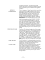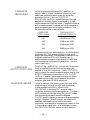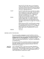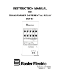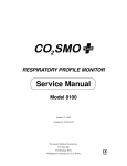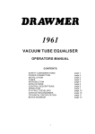
1
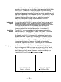
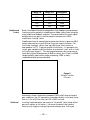
OPERATING AND MAINTENANCE
INSTRUCTION MANUAL
“DAVID-II”
——— MODEL 716 ———
FM-STEREO PROCESSOR / GENERATOR
__________
—– USER’S RECORD —–
Model 716 - Serial No. _______
Date Purchased _____________
Warranty Card Mailed — ¨
OPERATING AND MAINTENANCE
INSTRUCTION MANUAL
DAVID-II
—–—— MODEL 716 ———–
FM-STEREO PROCESSOR / GENERATOR
October, 1995
1305 Fair Avenue, Santa Cruz, CA
95060
TEL: (408) 458-0552 – FAX: (408) 458-0554
TABLE OF CONTENTS
Section I - INTRODUCTION
Model 716 Product Description ........................................................................................... 3
General - Features
Model 716 Technical Specifications..................................................................................... 3
Patent Notice ........................................................................................................................ 4
Block Diagram ...................................................................................................................... 5
Section II - Installation
Unpacking and Inspection ................................................................................................... 6
Mounting ............................................................................................................................... 6
Rack Requirements - Heat Dissipation
AC (Mains) Power ................................................................................................................. 6
As Delivered - Voltage Selector - Power Cord
Radio Frequency Interference (RFI) .................................................................................... 7
Location - Ground Loops
Line Input and Input Range Selection ................................................................................. 7
Input Connections - Balanced Inputs - Unbalanced Inputs Input Gain Range - Gain Jumpers
Pre-Emphasis Selection ....................................................................................................... 9
“Bass-Enhance” Equalization .............................................................................................. 9
“Bass-Enhance” Jumpering
Subcarrier Input................................................................................................................... 11
Composite Output .............................................................................................................. 11
Output Ground Loops
Section III - Setup and Operation
Panel Controls and Indicators ........................................................................................... 12
(All Controls and Indicators Defined According to Function)
Normal Setup Procedure .................................................................................................... 15
Input Gain Calibration - Output Level Adjustment
Average Compression Adjustment .................................................................................... 17
Composite Processing ....................................................................................................... 17
— 1 —
Section IV - Calibration
Calibration .......................................................................................................................... 18
Equipment Required - Power Supply Check - Clock Set Low-Pass Filter Matching - Crosstalk Trim - Separation Trim
Section V - Circuit Descriptions
Circuit Descriptions ............................................................................................................ 23
Component Annotation - A PWM Primer - PWM Ramp
Circuitry - Signal Path Circuitry - Input Stages - AGC Stage Wideband Compression and Limiting - High Frequency
Limiter - Filter Overshoot Compensator - Low-Pass Filter Pilot and Subcarrier Generation - Power Supply
Section VI - Appendix
Parts Lists - Schematics - Warranty .............................................................................. 35
— 2 —
Section I
INTRODUCTION
MODEL 716 PRODUCT DESCRIPTION
General
Inovonics introduced the first “DAVID” (as in David vs. Goliath) FMStereo Processor/Generator in 1992. The original Model 715 was the
hallmark of simplicity, and was intended to answer the more basic of
FM radio broadcasting needs.
The “DAVID-II,” Model 716, includes a redesigned pulse-widthmodulation audio processing section. This improved processing
circuitry extends the applicability of the DAVID-II into broadcast
environments where perceived loudness and modulation density are
considered germane to the broadcaster’s success.
Features
Features of the Inovonics DAVID-II include:
•
Comprehensive stereo audio processing: slow, “gainriding” AGC — Wideband Compression and Peak
Limiting — Independent High Frequency Limiting.
•
Exclusive “Bass Enhance” equalizer (defeatable).
•
Extended-response low-pass filtering with proprietary
overshoot compensation.
•
Digital synthesis of pilot and subcarrier for unexcelled
performance and freedom from drift and routine
adjustment.
•
Internal combining for RDS or SCA subcarriers.
•
Built-in, adjustable Composite Processor.
MODEL 716 TECHNICAL SPECIFICATIONS
Frequency Response (through
appropriate de-emphasis network):
±0.5dB, 20Hz–15kHz; –1dB or
less at 16kHz, –60dB or better at
19kHz.
Stereo Separation (LàR or RàL):
Processing OUT: >65dB,
20Hz–16kHz.
Processing IN: >60dB,
20Hz–16kHz.
— 3 —
Distortion (with full Compression,
1dB below 100% modulation):
<0.25% THD in demodulated
audio above 200Hz.
Noise:
Better than 80dB below 100%
modulation in demodulated audio,
20Hz–16kHz. 38kHz residual and
“digital” noise above 54kHz,
–70dB or better.
Crosstalk (MàS or SàM):
Processing OUT: nonlinear
crosstalk –55dB or better.
Processing IN: overall crosstalk
–50dB or better
Compressor/Limiter:
Fast-acting peak limiter with
secondary “platform” time
constant to compress dynamic
range with average-value
weighting. Independent high
frequency limiter conforms to
selected pre-emphasis
characteristic. Subsequent
program signal clipping is
relegated to non-repetitive limiter
overshoots 1ms or less in duration.
Stereo Pilot:
19kHz, ±1Hz; injection level
adjustable between 6% and 12%,
relative to 100% modulation.
Program Line Inputs:
Active-balanced/bridging;
accommodate nominal “0VU”
input levels between –15dBu and
+15dBu.
Composite (Multiplex) Output:
Adjustable between 1V p-p and
8V p-p; 75-ohm source impedance.
SCA / RDS Input:
10K-ohms, unbalanced; accepts
SCA or RDS subcarrier signal
levels between –20dBu and 0dBu
for nominal 5% to 10% injection.
Composite Processor:
Adjustable from 0dB to 3dB
clipping of the 100%-modulated
multiplex waveform prior to pilot
injection.
Pre-emphasis:
Integral with split-band audio
processing. May be jumpered for
75µs or 50µs characteristic.
Digital Synthesis Sampling Rate:
608kHz (16X subcarrier
oversampling).
Power Requirements:
105–130VAC or 210–255VAC,
50/60Hz; 15 watts.
“Bass-Enhance” Equalizer:
Accentuates “perceived” bass
response at user’s option. (See
Figure 4, Page 10.)
Size and Weight:
1¾”H x 19”W x 7”D (1U);
7lbs (shipping).
AGC Amplifier:
Slow, 0.5dB/sec. correction for
long-term input level variations;
±10dB capture range.
BLOCK DIAGRAM
A simplified Block Diagram of the DAVID-II is shown on the facing
page. Generator circuitry is explained in detail under Circuit
Descriptions, Section V, which references Schematic Diagrams found in
the Appendix, Section VI.
PATENT NOTICE
Low-pass filter overshoot compensation circuitry used in the DAVID-II
is protected under U.S. Patent No. 4,737,725.
— 4 —
Figure 1 - Block Diagram, DAVID-II FM-Stereo Processor/Generator
— 5 —
Section II
INSTALLATION
UNPACKING AND INSPECTION
Immediately upon receipt of the equipment, inspect carefully for any
shipping damage. If damage is suspected, notify the carrier at once,
then contact Inovonics.
It is recommended that the original shipping carton and packing
materials be saved for future reshipment. In the event of return for
Warranty repair, shipping damage sustained as a result of improper
packing for return may invalidate the Warranty!
IT IS VERY IMPORTANT that the Warranty Registration
Card found at the front of this Manual be completed and
returned.
Not only does this assure coverage of the
equipment under terms of the Warranty, and provide some
means of trace in the case of lost or stolen gear, but the user
will automatically receive specific SERVICE OR MODIFICATION INSTRUCTIONS should they be issued by Inovonics.
MOUNTING
Rack
Requirement
Heat Dissipation
Inovonics’ DAVID-II is packaged to mount in a standard 19-inch
equipment rack and requires only 1¾ inches (1U) of vertical rack
space. The use of plastic “finishing” washers is recommended to
protect the painted finish around the mounting holes.
Consuming no more power than a small child’s night-light, heat
generated by the DAVID-II is insignificant. The unit is specified for
operation within an ambient temperature range of freezing to 120°F/
50°C. Because adjacent, less efficient equipment may radiate
substantial heat, be sure that the equipment rack has sufficient
ventilation to keep the temperature below the stated maximum.
AC (MAINS) POWER
As Delivered
Unless specifically ordered for export shipment, the DAVID-II is set at
the factory for operation from 115V, 50/60Hz AC mains. The rearpanel designation next to the fuseholder will confirm both the mains
voltage selected and the value of the fuse supplied.
— 6 —
Voltage Selector
A mains voltage selector switch is located beneath the top cover of the
unit, adjacent to the AC mains connector on the circuit board. With
primary AC power disconnected, slide the red actuator with a small
screwdriver so that the proper mains voltage (115 or 230) is visible.
You must always install an appropriate fuse, and should mark the rearpanel voltage/fuse designation. It is factory practice to cross-out the
inappropriate marking with an indelible black marking pen. You can
remove this strikethrough with solvent to redesignate.
BE SURE that the mains voltage selector setting and primary fuse value are appropriate for the mains supply before
plugging the DAVID-II into the wall outlet.
Power Cord
The detachable power cord supplied with the DAVID-II is fitted with a
North-American-standard male plug. The individual cord conductors
are supposed to be color-coded in accordance with CEE standards:
BROWN = AC “HOT”
BLUE = AC NEUTRAL GRN/YEL = GROUND
If this turns out not to be the case, we offer our apologies (cord vendors
vary) and advise that U.S. color coding applies:
BLACK = AC “HOT”
WHITE = AC NEUTRAL
GREEN = GROUND
RADIO FREQUENCY INTERFERENCE ( R F I )
Location
Ground Loops
Although we have anticipated that the DAVID-II may be operated
adjacent to high-power transmitters, you should exercise care in
locating the unit away from abnormally high RF fields.
In some installations a mains frequency or RF ground loop may be
formed between the input or output cable shield grounds and the AC
power cord ground. Use of a “ground-lifting” AC adapter should
remedy the situation, though the chassis ultimately must be returned
to earth ground for safety. Generally, being screwed-down in the
equipment rack will satisfy this requirement.
LINE INPUT AND INPUT RANGE SELECTION
Input
Connections
Balanced Inputs
The DAVID-II has electronically-balanced (transformerless) left and
right channel PROGRAM LINE INPUTS. These are brought out to a
screw-terminal barrier strip on the rear panel and include chassis
ground connections for cable shields. Please note that the screwterminal barrier block can be unplugged from the chassis! This makes
connection a bit easier and permits quicker removal of the DAVID-II
from the rack should maintenance ever be required.
A balanced program audio feed to the DAVID-II will use both the +
and the – terminals, plus the associated G, for each of the two stereo
channels. Since these are “bridging” (high impedance) inputs, they
— 7 —
channels. Since these are “bridging” (high impedance) inputs, they
provide no termination for the console or other equipment which feeds
the DAVID-II. Please feel at liberty to connect a 600-ohm resistor
across the input terminals should you feel this really necessary. Most
professional equipment nowadays features low output impedances and
high input impedances. The concept of 600-ohm “line-matching” dates
from the age of transformer coupling and is rooted in the mystique of
telephone practices. More often than not, audio line impedance
matching is poo-pooed by today’s hip broadcasters (you) and
equipment manufacturers (us).
Unbalanced
Inputs
Input Gain
Range
In rare instances the DAVID-II may be fed from “semi-pro” gear with
unbalanced outputs. “Disco” mixers fall into this category and are
perfectly serviceable for installations on a tight budget. In such cases,
the single center conductor of the shielded input lead should be
connected to the + terminal, and the shield to G. In addition, a
jumper wire should be installed between the – terminal and G.
The DAVID-II can accommodate line-level program inputs with a
nominal “Zero-VU” value between –15dBu and +15dBu. This 30dB
range is divided into two 15dB ranges by internal jumpering.
As shipped, the DAVID-II is jumpered for professional level inputs
between 0dBu and +15dBu. Most console and STL receiver outputs
fall into this range, +4dBu, +6dBu and +8dBu being typical levels.
Lower levels, between –15dBu and 0dBu, may be encountered when
interfacing with “semi-pro” gear or with feeds via lossy studiotransmitter telephone line circuits. The extra gain for the low level
range is enabled by changing jumpers beneath the top cover.
Gain Jumpers
Under the top cover, and just behind the PROGRAM LINE INPUT
barrier strip, you will find two jumper pin strips, each with a “pushon” jumper. The strips are identified as JMP3 and JMP5 in the circuit
board legend, and each has an H and an L marking to indicate the
proper jumper placement for High level and for Low level inputs,
respectively. Figure 2 illustrates jumpering options.
HIGH LEVEL INPUTS
(0dBu to +15dBu)
LOW LEVEL INPUTS
(–15dBu to 0dBu)
Figure 2 - PROGRAM LINE INPUT Range Selection
— 8 —
PRE-EMPHASIS SELECTION
The DAVID-II supports the 75-microsecond FM broadcasting preemphasis standard, common to the Western Hemisphere and parts of
the Orient, and the 50-microsecond standard used in Europe and Asia.
Pre-emphasis appropriate to the shipping destination is jumpered at the
factory, but this is easily changed if necessary.
Beneath the top cover, locate the second vertical row of integrated
circuits from the right-hand edge of the chassis. This is the row next to
the one behind the input barrier strip. Between the second and third
ICs from the rear panel are two jumper pin strips, each with a push-on
jumper. These are identified as JMP1 and JMP2 in the circuit board
legend, and each is designated with a 75 and a 50 marking to indicate
proper jumper placement for the 75µs and 50µs pre-emphasis
characteristics. Figure 3 illustrates the jumpering options
75-MICROSECOND
50-MICROSECOND
Figure 3 - Pre-emphasis Jumpering
“BASS-ENHANCE” EQUALIZATION
The DAVID-II incorporates a unique bass-boost equalizer which may be
enabled at the user’s option.
Normal DAVID-II low-end response is flat to within 1dB down to 10Hz.
When the equalizer is jumpered into the circuit, response assumes the
shape graphed in Figure 3 on the next page. The effect of this
equalization is to increase the amount of perceived “bottom end,” while
attenuating much of the sub-audible program energy. Very lowfrequency bass notes are lost in nearly all listening situations, only
serving to sabotage modulation efficiency and program density. Even
the megawatt subwoofers in cars with blacked-out windows don’t
respond to frequencies much below 50Hz; rather, they make a lot of
noise in the rather narrow region between 60Hz and 80Hz.
The few dB of boost just before cutoff more than makes up for any lost
legitimate program bass information. This is analogous to the
Rheinfelder Effect, a phenomenon associated with a novel audio noise-
— 9 —
reduction technique which employs a similar boost-before-cutoff at the
high-frequency end of the spectrum.
Figure 4 - “Bass-Enhance” Equalization Curve
“Bass-Enhance”
Jumpering
As delivered from the factory, “Bass-Enhance” equalization is defeated.
To enable the “Bass-Enhance” equalizer, remove the top cover and
locate the first vertical row of integrated circuits closest to the righthand side of the chassis, the one just behind the PROGRAM LINE
INPUT barrier strip. Close to the front panel, and just to the right of
the two INPUT GAIN controls, you’ll find two jumper pin strips, each
with a push-on jumper, labeled JMP4 and JMP6. Each strip is marked
with the letters F and B, indicating jumper placement for Flat and
Bass-Enhance, respectively. Figure 5 illustrates the jumpering options.
FLAT RESPONSE
“BASS-ENHANCE” RESPONSE
Figure 5 - “Bass-Enhance” Jumpering
— 10 —
SUBCARRIER INPUT
Internal combining is provided for an RDS or an SCA auxiliary
subcarrier. The rear-panel SUBCARRIER INPUT connector is an
unbalanced input with a load impedance in the neighborhood of
10K-ohms.
An RDS subcarrier normally accounts for 5% or less of the total
composite multiplex output signal, making it 26dB or more below peak
program modulation. SCA subcarriers typically have a higher injection
level, about 10%, or 20dB below program peak deviation. Subcarrier
inputs ranging in level between –20dBu and 0dBu may be fed to the
SUBCARRIER INPUT connector, and can be regulated to the proper
injection level by the front-panel SUB INJ. level control.
COMPOSITE OUTPUT
The unbalanced COMPOSITE OUTPUT of the DAVID-II has a resistive
source impedance of 75 ohms. This permits runs of moderate length
(about 50 feet, maximum) to the exciter or microwave link input. If the
cable length is more than just a few feet, the cable, itself, should have a
75-ohm characteristic impedance and be terminated in 75 ohms at the
far end.
A Stereo Generator must always be connected to an exciter or link (STL)
input specifically intended for multiplex stereo. This is a “flat” input,
rather than a monaural program input with signal pre-emphasis.
Program signal pre-emphasis is imparted by the DAVID-II.
Output Ground
Loops
Because the Stereo Generator output and the exciter input are both
unbalanced, it is best to locate the DAVID-II near the exciter and
power both from a common AC mains circuit. This will help avoid
ground loops and mains-related hum in the transmitted signal.
— 11 —
Section III
SETUP AND OPERATION
PANEL CONTROLS AND INDICATORS
A brief description of the front-panel controls and indicators is given
here. Do scan this section to at least verify that our terminology agrees
with yours.
PLEASE NOTE that all front-panel multiturn trim controls require
fifteen to twenty complete rotations of the adjusting screw to cover their
total operating range. Depending on the trim-pot manufacturer, the end
of the range may, or may not, be identified by a “click-click” sound or
other audible/tactile sensation.
INPUT GAIN
These two controls, at the far-right end of the front
panel, adjust DAVID-II sensitivity for the nominal
program level applied to the LEFT and RIGHT channel
PROGRAM LINE INPUT barrier strip terminals on the
rear panel. The controls have a 15dB range which is
multiplied by input gain range jumpering to an input
acceptance range of 30dB (see Page 8). The INPUT
GAIN controls are adjusted to maintain AGC gain in
the center of its operating region.
A G C GAIN
This series of five LED indicators displays the amount
of correction in effect for long-term variations in the
program input signal. The AGC circuit is left/right
correlated; that is, the overall circuit gain is controlled
by the greater of the left or right channel signals. This
prevents the stereo image from “wandering.”
The correction rate of the AGC circuit is intentionally
very slow, 10dB of gain correction will take
approximately 20 seconds. With a conscientious
operator on the console, the indicated AGC GAIN will
appear “stuck” at the center, 0dB indicator.
The “safe” operating zone of the circuit is within the
central three green LEDs. If either the +10dB or the
–10dB red indicator is lighted to full brightness, the
input program signal is out of limits and the reason
should be found and corrected.
GATE OPEN
The DAVID-II AGC is “gated.” This means that
during brief pauses in the program AGC gain is locked
to prevent background sounds from increasing to
unnatural proportions. The green GATE OPEN
— 12 —
unnatural proportions. The green GATE OPEN
indicator will remain continuously lighted during most
music programming, but will blink off during pauses
in speech.
AVERAGE
COMPRESSION
This is, in essence, a “drive” control at the input of the
compressor/limiter stage, affording the user control
over program density. When fully counterclockwise
(MIN) the broadcast signal will retain most of the
dynamics of the source material. As the control is
rotated clockwise, compression and limiting will
increase, reducing the program dynamic range and
effectively raising the average modulation by the dB
values shown.
A full-clockwise setting of the AVERAGE COMPRESSION control will be found tolerable for hard rock
music, but a setting of 6dB to 8dB may sound better
with most other “pop” program material. Classical
music will probably demand an even lower setting.
The effect of the AVERAGE COMPRESSION control is
not instantaneous. There is as much as a one-second
delay between adjusting this control and hearing any
change.
COMPRESSOR GAIN
These two LEDs display the gain state of the average
level compression circuitry. With a steady-state tone,
or with no input signal present, the compressor is in
“equilibrium” and both indicators will be lighted to
half-brightness. When the compressor is reducing
circuit gain, the red – LED will grow brighter. When
compressor gain is increasing, the green + indicator
will brighten. This pair of LEDs shows not only in
which direction compressor gain is headed, but can be
interpreted for how hard the compressor is working as
well.
PEAK LIMITING
The W.B. and the H.F. indicators display action of the
wideband and the independent high frequency limiters,
respectively. Relative limiter activity is directly
proportional to the activity of the LEDs.
FILTER COMP.
Proprietary circuitry preceding the primary low-pass
filter inhibits overshoots which would otherwise
compromise full modulation of the carrier. Action of
the overshoot compensation circuitry is displayed by
the FILTER COMP. indicator. It is normal for this LED
to flash almost continuously when “bright” music is
being broadcast.
— 13 —
COMPOSITE
PROCESSING
In the fully-counterclockwise (OUT) position, an
output “safety” clipper catches only those very fast
peaks and overshoots which sneak by the earlier
protection circuitry. As the COMPOSITE
PROCESSING control is rotated clockwise, the level
applied to the safety clipper is increased by the dB
value indicated on the front panel. Composite clipping
will increase apparent loudness, but at the expense of
generating some spurious harmonic products. The
following tabulation is approximate.
COMPOSITE
PROCESSING
PEAK VALUE OF
CLIPPING PRODUCTS
OUT
>60dB below 100%
1dB
50dB below 100%
2dB
45dB below 100%
3dB
40dB below 100%
Composite clipping is performed prior to 19kHz stereo
pilot insertion. This averts clipping or other pilot
amplitude modulation. Nevertheless, crosstalk of the
program audio into RDS or SCA subcarriers is
exacerbated by composite clipping and its inevitable
intermodulation and harmonic generation. Use this
feature sparingly!
COMPOSITE
OUTPUT / PILOT / SUB
The PILOT INJ. and SUB INJ. controls set the injection
levels of the 19kHz stereo pilot and an externallyapplied SCA or RDS subcarrier. The OUTPUT LEVEL
control varies the overall composite output level of the
DAVID-II delivered to the exciter or STL. OUTPUT
LEVEL is a “master” adjustment and does not affect
the relationships (level ratios) between the stereo
program, pilot and RDS/SCA subcarrier.
AUDIO PROCESSING
In the IN position, this switch routes the input audio
program signal through the AGC and compressor/
limiter processing circuitry. When AUDIO
PROCESSING is switched OUT, program audio
completely bypasses the processing section. The green
LED indicates normal operation, the red LED shows
that processing has been manually defeated.
The OUT position defeats program audio pre-emphasis
as well. However, “Bass-Enhance” equalization (if
enabled), low-pass filtering (and its overshoot
correction), and composite processing do remain active
in the program signal path. It is important to leave
the AUDIO PROCESSING switch in the IN position
— 14 —
the AUDIO PROCESSING switch in the IN position
unless outboard provision is made for pre-emphasis
and limiting. Without external pre-limiting, program
material will be driven hard into the clipping circuits
and result in egregious distortion..
PILOT
The PILOT switch lets the user manually turn off the
19kHz stereo pilot for certain tests. Since the 19kHz
pilot is necessary for proper system operation, the
switch should always be left ON. The green LED
indicates normal operation, the red LED lights
whenever the pilot has been turned off.
MODE
Under some circumstances it may be advisable to
broadcast monaurally. For example, should the
station suddenly suffer an emergency power loss,
temporarily reverting to mono transmission would
help regain some of the lost coverage until full power is
restored.
When switched to MONO, the MODE switch removes
both the stereo subcarrier and the 19kHz pilot. The
transmitted signal will consist of L+R, the algebraic
sum of the left and right program channels. The
MODE switch does not remove an RDS or an SCA
subcarrier.
POWER
‘Nuf said.
NORMAL SETUP PROCEDURE
This setup procedure presupposes a normal installation with the
DAVID-II PROGRAM LINE INPUT fed directly from the output of the
audio console and a direct connection of the COMPOSITE OUTPUT to the
wideband input of an exciter/transmitter. Variations from these
conditions, such as an intermediate STL (or other link) in either the
input or the output path of the DAVID-II, may call for considerations
not addressed here.
At this point the DAVID-II should be installed in the program chain
with power applied, and have all front-panel function switches ON.
AVERAGE COMPRESSION should be set at 6dB and COMPOSITE
PROCESSING turned OUT.
Input Gain
Calibration
Left (L) and right (R) INPUT GAIN controls are set individually to
center the AGC operating range at the nominal “Zero-VU” program
line input level. If the following procedure shows control range to be
outside adjustment limits, recheck circuit board jumpering for Line
Input Range Selection as described on Page 8.
— 15 —
1. To the left channel only, apply a 500Hz test tone from the console
at a level 2.5dB above normal reference level. This is simply a
console VU meter indication of +2.5VU.
2. Adjust the left channel (L) INPUT GAIN control so that both the 0dB
and the –5dB AGC GAIN indicators light to equal brilliance.
Remember that the AGC circuit responds slowly to level changes, so
have patience in performing this step of the procedure.
3. Turn off the +2.5VU test signal to the left channel and apply
+2.5VU to the right channel only.
4. Adjust the right channel (R) INPUT GAIN control so that both the
0dB and the –5dB AGC GAIN indicators light to equal brightness.
This completes INPUT GAIN adjustment. The DAVID-II may now be
fed normal stereo program material from the console. If this
procedure has been performed properly, and the operator pays
reasonable attention to console metering, the AGC GAIN indicators will
always remain the green-LED “safe operating” zone between –5dB and
+5dB.
Output Level
Adjustment
Perform this part of the procedure “on-air” under normal operating
conditions, and using typical program material. You also must have
access to the station’s Modulation Monitor. An RDS or SCA subcarrier
should not be connected until Step #6. Be sure that the COMPOSITE
PROCESSING control is OUT; that is, fully counterclockwise.
PLEASE be certain that you understand operation of the ModMonitor, and that it is properly calibrated and connected to the correct
transmitter/exciter RF sample point.
1. Put the Mod-Monitor in its “Total Peak Modulation” measurement
mode with peak flasher(s) set to 100%.
2. Turn the AVERAGE COMPRESSION control fully clockwise (10dB).
With normal program fed to the DAVID-II (at the level which
maintains AGC GAIN in the center of its range), adjust the OUTPUT
LEVEL control for a Mod-Monitor indication of frequent 100%modulation peaks.
3. Back-down the OUTPUT LEVEL control slightly, so that the 100%
peak flasher(s) light only occasionally.
4. Switch the Modulation Monitor to display the injection level of the
19kHz stereo pilot.
5. Adjust the PILOT INJ. control for a 9% Mod-Monitor reading of pilot
injection.
6. (OPTIONAL) If an RDS or an SCA subcarrier is to be broadcast,
connect it to the DAVID-II (or other combining point) at this time.
Using the Mod-Monitor, or other means of reading the auxiliary
subcarrier injection level, adjust the SUB INJ. level control (or other
subcarrier level control) for the proper injection. This is normally
— 16 —
subcarrier level control) for the proper injection. This is normally
about 5% for an RDS subcarrier, 10% for an SCA.
7. Put the Mod-Monitor back into its “Total Peak Modulation”
measurement mode and, if necessary, trim the OUTPUT LEVEL
control so that the peak flasher(s) indicate only occasional 100%
peaks.
NOTE: Depending on current operating rules and practices, when
either an SCA or an RDS subcarrier is broadcast, total peak carrier
deviation may be permitted to exceed the customary 100%-modulation
figure. The station (or consulting) engineer should be aware of legal
guidelines in effect and assume responsibility for any adjustment which
deviates from this procedure.
AVERAGE COMPRESSION ADJUSTMENT
Once the OUTPUT LEVEL has been set for proper carrier peak deviation,
the user may determine a setting for the AVERAGE COMPRESSION
control based on listening tests. A guideline already expressed has
stated that “hard rock” formats may use any AVERAGE COMPRESSION
setting up to 10dB, probably without ill effect. More conservative
practice, particularly on “mellower” formats, would dictate a 6dB to 8dB
maximum setting.
COMPOSITE PROCESSING
This control will have a definite effect on program “loudness,” but not
without some tradeoff for distortion or probable interference between
the main program and any auxiliary subcarriers. Please see the
discussion under COMPOSITE PROCESSING on Page 14.
— 17 —
Section IV
CALIBRATION
The upgrade to PWM processing has greatly simplified calibration of the
DAVID-II when compared with its predecessor, the Model 715 DAVID.
The number of trimmer adjustments under the top cover has been
reduced from nineteen(!) to only eight.
“Routine” calibration of the DAVID-II is never required. The PWM
processing and digital-synthesis circuitry is simple and stable. The only
justification for confirming any of the internal adjustments is out-ofspecification operation, and only after all other possible faults have been
considered and eliminated. It’s worth a call to the factory to discuss any
anomalies before charging-ahead and possibly making things worse.
Equipment
Required
•
Dual-Trace Oscilloscope — 5mV sensitivity, 20Mhz bandwidth,
with two matched 10:1 probes.
•
Audio Generator — 10Hz–1MHz, +20dBm output capability.
•
Digital Multimeter
•
Frequency Counter — capable of accurate frequency
measurement from 1kHz to 2Mhz.
•
“Precision” FM-Stereo Demodulator — station Mod-Monitor
with input for composite baseband signal.
•
Spectrum Analyzer (optional*) — must have good resolution in
the 100Hz to 100kHz (FM composite baseband) display range.
* The Spectrum Analyzer is not required if the “Precision” FMStereo Demodulator is capable of resolving crosstalk, stereo
separation and 38kHz “residual” measurements to a figure of
70dB or better.
Power Supply
Check
Clock Set
1. Apply power to the DAVID-II.
2. Check that the positive and negative 9-volt regulated supplies are
between 8.5V and 9.0V. You can check these on pin 8 (positive) and
pin 4 (negative) of any 8-pin IC.
3. Use one of the low-capacitance ‘scope probes to connect to the input
of the frequency counter. Check the clock frequency on pin 11 of
IC8.
4. Adjust C16, the trimmer capacitor to the right of the crystal, for
exactly 1,216,000Hz.
— 18 —
Low-Pass Filter
Matching
The low-pass filter for the left program channel is not adjustable;
rather, it employs close-tolerance components to meet design
parameters. Since close frequency and phase response matching
between stereo channels is essential to acceptable Stereo Generator
crosstalk performance, trim controls have been included in the right
channel filter so that it may be tuned to match left channel response.
1. Set the AUDIO PROCESSING switch to the OUT position.
Frequency and phase response matching is optimized with all
processing bypassed.
2. Clip the two ‘scope probes to the output of the filter buffer
amplifier, IC20. The most convenient monitor points are the righthand ends of R22 and R27, for the left and right channels,
respectively. The right-hand ends of the resistors are the ends
closest to the COMPOSITE OUTPUT connector.
3. Apply a 10kHz sinewave test signal to both the LEFT and the RIGHT
PROGRAM LINE INPUT. This is most simply done with clip-leads if
the barrier screw-strip is first unplugged from the chassis. Connect
the “hot” side of the oscillator output to both + terminals, the
grounded side of the Audio Generator output to either G. The –
input terminals may be left unconnected for test purposes.
4. Set both ‘scope attenuators at 2V/div. Position the left channel
signal (from R22) above the right.
5. Adjust the Audio Generator amplitude for a 6-volt (3 divisions)
peak-to-peak signal on both ‘scope traces. If necessary, trim either
the L or R front-panel INPUT GAIN control so that both traces are
equal in amplitude.
6. Increase the Audio Generator frequency to the first filter null,
approximately 19.1kHz. Observing the upper (left channel) trace,
down-range both oscilloscope vertical attenuators and fine-tune the
Audio Generator frequency for the deepest null in the left channel
signal.
HINT: When properly nulled, the signal waveform will be very close to
the noise floor. If you find the nulled signal difficult to resolve, try
triggering the ‘scope timebase directly from the Audio Generator. This
will make the waveform “hold still” and stand out from the (random)
noise.
7. When the Audio Generator has been fine-tuned to null the left
channel, adjust R112 (between IC26 and IC27) for a null in the
right channel filter. Both channels should null to the same relative
amplitude.
8. Increase the Audio Generator frequency to the second filter null,
approximately 21.8kHz. Again, fine-tune the Audio Generator
frequency for the deepest null in the left channel signal.
— 19 —
9. Adjust R65 (between IC21 and IC22) for a right-channel null.
NOTE: The third filter null is at approximately 34.5kHz. Rather than
to match frequency response between channels at this point, the third
filter adjustment is used to help match phase response in the next
procedure.
Crosstalk Trim
If your station Mod-Monitor includes a true “precision” FM-stereo
demod (crosstalk/separation resolution of 70dB or better), it may be
used in lieu of a Spectrum Analyzer for this part of the Calibration
Procedure. If a Mod-Monitor of insufficient precision is used, final
Calibration (and performance!) of the DAVID-II will reflect the
inaccuracy.
1. Connect the COMPOSITE OUTPUT of the DAVID-II to the input of
the Spectrum Analyzer (or directly to the Composite Input of the
Mod-Monitor).
2. Turn the output of the Audio Generator completely off.
3. With the DAVID-II MODE switch in STEREO, and PILOT switch
ON, adjust either the front-panel OUTPUT LEVEL control (or the
Spectrum Analyzer or Mod-Monitor input gain attenuator) for a
19kHz pilot reading of –20dB (10% injection).
4. Adjust R20 (between IC12 and IC17) to null the 38kHz secondharmonic-distortion component of the stereo pilot. The Spectrum
Analyzer should display the 38kHz component at the noise floor;
the Mod-Monitor should indicate a 38kHz “residual” reading at the
bottom of its most sensitive scale (–70dB or better).
5. Next, re-apply the Audio Generator test signal to the LEFT and
RIGHT PROGRAM LINE INPUT of the DAVID-II as described in Step
3 of the Low-Pass Filter Matching section of this Procedure. The
Audio Generator frequency should be set to 1kHz, and the level set
the same as before. If in doubt about the level, check for 6-volt p-p
signals on the right-hand ends of R22 and R27.
6. Monitor the “sub channel.” This is the 38kHz double-sideband,
suppressed-carrier component on the Spectrum Analyzer (or an
“L–R” Mod-Monitor reading).
7. Carefully adjust the front-panel INPUT GAIN L control for a null in
the sub channel.
8. Adjust R157 (to the left of IC35) to further null the sub channel.
NOTE: Because the effect of the two preceding adjustments will
appear to interact, it will be necessary to repeat Steps 7 and 8 until no
further improvement in the sub-channel null can be achieved.
9. Increase the Audio Generator frequency to 10kHz. Adjust R111
(between IC24 and IC25) for the best null in the sub channel at
10kHz.
10. Repeat Steps 7, 8 (at 1kHz) and 9 (at 10kHz) until the sub-channel
null at both frequencies is at maximum. You may wish to “split the
difference” to balance crosstalk measurements, sacrificing a null at
— 20 —
difference” to balance crosstalk measurements, sacrificing a null at
one frequency to improve that at the other.
When this part of the Calibration Procedure has been successfully
completed, the sub-channel measurement should remain below –50dB
(relative to 100% modulation) as the Audio Generator is swept from
20Hz to 15kHz.
Because the DAVID-II utilizes digital techniques (instead of analog
multiplication) to generate the subcarrier, crosstalk is symmetrical;
that is, sub-to-main crosstalk will be identical with the main-to-sub,
which was optimized in the foregoing Procedure.
Separation Trim
The traditional method of adjusting and verifying stereo separation is
to visually monitor an oscilloscope display of the composite multiplex
signal (one channel driven and stereo pilot off), and adjust for the
straightest baseline of the DSB waveform. Although this technique
does permit a rough separation calculation, even today’s best ‘scopes
will show baseline distortion when overdriven to the extent necessary
to resolve separations of 40dB or more. For the high figures of
separation which modern stereo generators can achieve, a precision
stereo demodulator will give much greater measurement and,
consequently, adjustment accuracy.
It is entirely feasible to trim the equalization and phase adjustments in
the DAVID-II output circuitry to correct for shortcomings elsewhere in
the transmission system; for instance, in a “composite” STL, or even in
a long run of coax cable. This procedure does not consider this option,
however, assuming instead that, since a chain is only as strong as its
weakest link, it’s better to fix the weak link than to compensate for it
at another point. The procedure which follows will leave the DAVID-II
adjusted for its own best stereo separation.
1. Cable the COMPOSITE OUTPUT of the DAVID-II directly to the
composite input connection of the Mod-Monitor. Use a short cable
of known characteristics, preferably 50-ohm or 75-ohm coax.
2. With the DAVID-II in the STEREO mode and with the PILOT
switched ON, apply a 10kHz sinewave signal to the left channel
input only. The signal level should be identical with that used in
previous procedure steps. If in doubt, check for 6-volts p-p on R22.
3. At this point, check the Mod-Monitor’s display of Total Peak
Modulation. It should read just about 100%. Adjust the DAVID-II
OUTPUT LEVEL control for an exact 100% reading.
4. Also check the Mod-Monitor indication of Pilot Injection Level. If
necessary, adjust the DAVID-II PILOT INJ. control for a 9% reading.
5. Switch the Mod-Monitor to display left and right channel levels.
The left channel should measure about –1dB. Ideally, the right
channel should read –70dB.
— 21 —
6. Adjust the equalization and phase trimmers, R56 and R57, for best
stereo separation. There is some interaction between these two
adjustments, but there will be only one setting of each which will
give best separation. Null one, then the other, and back-and-forth,
etc., until no further improvement can be had. The final
adjustments should yield best separation at all frequencies between
20Hz and 15kHz, left-into-right and right-into-left.
— 22 —
Section V
CIRCUIT DESCRIPTIONS
This section details the circuitry of the Inovonics DAVID-II. Circuit
descriptions refer to the two pages of Schematic Diagrams contained in
the Appendix, Section VI, Pages 39 and 40.
Component
Annotation
DAVID-II Schematics may appear to be annotated in a somewhat
haphazard manner, insofar as component reference designations are
concerned. Rather than annotate the schematic in a logical sequence,
we have instead chosen to designate the components on the circuit
board, top-to-bottom, left-to-right, following the physical placement of
the parts in their neat little rows. It is our expectation that this
practice will aid any required troubleshooting, making it easier to
locate the physical part or test point from an analysis of the circuit
diagram.
The first part of this section covers the general subject of Pulse Width
Modulation (PWM) as it applies to the audio processing circuitry.
Signal path circuitry discussions follow.
A PWM PRIMER
PWM Gain
Control
The DAVID-II utilizes Pulse-Width Modulation techniques rather than
voltage-controlled amplifiers or FET attenuators in its three distinct
processing sections. This technology, as applied to broadcast audio
processing, was pioneered by Inovonics in 1982. PWM is a simple,
colorless, quasi-digital method of linear gain control which avoids the
several hassles associated with more expensive, possibly single-sourced
VCA ICs or matched and balanced FET devices. Our implementation
of PWM utilizes the popular 4000-series CMOS parts which are dirt
cheap and available nearly anywhere.
PWM sets the gain of an analog circuit simply by sampling, or
“chopping,” the analog signal; that is, turning it on and off at a rapid
rate. Consider an audio program signal which can be turned on and off
with a toggle switch. When the switch is on, attenuation is zero. When
off, attenuation is infinite. If we satisfy Dr. Nyquist’s requirement and
toggle this switch at a rate at least twice that of the highest audio
frequency, linear signal attenuation becomes directly proportional to
the OFF time as depicted in the chart on the next page.
The DAVID-II sampling rate is 152kHz, better than ten times the
highest program audio frequency. Since this is well above the Nyquist
rate, anti-aliasing and reconstruction filters can be simple and gentle.
— 23 —
Feedforward
Control
Switch ON
Switch OFF
Attenuation
100%
0%
0dB
50%
50%
6dB
25%
75%
12dB
10%
90%
20dB
1%
99%
40dB
Both the wideband and the independent high frequency compression/
limiting circuits operate in a feedforward mode, rather than using the
more traditional feedback method. The amplitude of the input signal
establishes circuit gain to hold the output constant at a 100%modulation “ceiling” value.
Feedforward control necessitates a conversion factor to give one dB of
output attenuation for each dB that the input signal increases. Put
into linear (voltage), rather than log (dB) terms, this function is
expressed as X=1/Y. Figure 6 graphs this function. X represents the
circuit gain needed to hold the output at a constant 1 volt, with a 1-volt
to 10-volt input signal Y. This technique becomes a bit precarious at
small duty cycles (attenuations of 40dB or more), but in the 0 to 30dB
range typically required for audio processing, PWM is easily
implemented and quite predictable.
Figure 6
Voltage Transfer
Function
Assuming a linear relationship between PWM on/off time and signal
gain reduction, the 1/Y expression translates directly to the duty cycle;
that is, 0.1 is a 10% on time, and 1.0 a 100% on time.
“Soft Knee”
In actual implementation we require a “threshold” level, below which
gain will remain at full value. Just above threshold, the transfer
function will conform to what has become known as a “soft knee”
characteristic. This means that the program signal eases gently into
— 24 —
characteristic. This means that the program signal eases gently into
compression and limiting, avoiding the abrupt change from a linear to
a limited state which characterizes traditional feedback topology. The
“soft knee” is normal behavior for feedforward gain control, and is
credited for the smoother, less fatiguing sound attributed to this
method.
The PWM
“Ramp”
Waveform
Figure 7 shows a “ramp” waveform generated by the DAVID-II to
effect the desired feedforward transfer characteristic. Note the
similarity between this waveform and Figure 6. Allowance has been
made for the “soft knee” compression and limiting threshold, and a
negative-going “pedestal” has been included to keep the CMOS analog
switches active, even when no gain reduction is in effect.
Figure 7
Ramp Waveform
This ramp runs continuously at a 152kHz rate. It is applied to one
input of a comparator, and a DC voltage derived from the input signal
is fed to the other comparator input. The comparator output is the
duty-cycle-modulated squarewave which “chops” the program audio
signal.
PWM RAMP CIRCUITRY
Master Clock
Referring to the second sheet of the Schematic on Page 40, IC8C is the
DAVID-II master “clock” running at 1.216Mhz, 64 times the stereo
pilot frequency. Binary dividers IC7A, IC3A and IC3B derive the
152kHz PWM switching frequency. This is buffered by IC8A and
IC8B, and is capacitor-coupled to the base of Q10. Q10, held in
saturation by R103, is momentarily turned off with each negative transition of the switching waveform. When Q10 turns off, Q9 turns on for
the same brief period. With Q8 serving as an “active pull-up resistor,”
Q9 delivers a stiff negative-going 200ns pulse at the 152kHz rate.
— 25 —
The negative-going pulse from Q9 triggers a similar event with Q6 and
Q7. On the positive transition of the pulse, Q6 is turned off, allowing
Q7 to turn on. C49 and R99 establish the off time for Q6, hence the on
time for Q7.
Compressor/
Limiter Ramp
When Q7 turns on, C52 is charged to very nearly the +9-volt power
supply rail through CR18. As soon as Q7 turns back off, C52 begins to
discharge through three distinct paths.
The cathodes of CR21 and CR22 are held at two different DC levels by
the attendant divider strings. This means that C52 initially discharges
through R134, R135, and the series connection of R113 and R114.
When the charge falls to about +6 volts, CR21 is biased out of the
circuit, removing R135 from the discharge path. As the charge
approaches +1 volt, CR22 removes R134, leaving the R113 and R114 to
discharge C52 the rest of the way. The effect is a quick initial
discharge of C52, slowing as the DC level drops. This yields the
modified X=1/Y waveform slope shown in Figure 7.
“Pedestal”
Because the LM319 fast comparators cannot deal with an input voltage
range which approaches the supply rails, the ramp is taken from the
R113/R114 divider. A fixed amount of the negative-going 200ns pulse
is coupled through R115 to this same point, creating the “pedestal”
mentioned earlier. Q11 is an emitter-follower buffer for the
“composite” ramp waveform, applying the ramp to the + inputs of
comparators IC42A and IC29A. These generate the PWM squarewave
switching waveform for the broadband and the independent high
frequency limiters, respectively.
AGC Ramp
The AGC function of the DAVID-II is a very slow “gain servo”
operating in a feedback rather than a feedforward mode. The AGC
requires a PWM ramp of a different shape; not for a proper gain
transfer characteristic, but to maintain a constant rate of AGC
correction.
Each time Q7 turns on, C84 is charged through CR40. Unlike the
complex discharge path of C52, C84 has a simple RC discharge through
R204 and R234. Since the AGC operates in a feedback mode, the shape
of this ramp is far less critical than the one for the wideband and high
frequency feedforward limiters. The AGC ramp is applied directly to
the + input of the third comparator, IC42B. Though Q7 initiates the
two ramp waveforms, CR18 and CR40 ensure that each can assume its
characteristic discharge shape.
Processor
Bypass
S4, the front-panel AUDIO PROCESSING switch, allows the user to
completely bypass the DAVID-II audio processing system. When S4 is
switched OUT, binary divider IC3B is inhibited. Lack of drive holds Q7
off which stops the AGC and limiting PWM ramps. This drives the
outputs of all three comparators low, opening the signal path at each
PWM attenuator. S4 also switches IC40A and IC40D to route the
program input signal around the processing circuitry.
— 26 —
SIGNAL PATH CIRCUITRY
NOTE: Left and right program channel circuits are identical, so only
the left channel will be described here. A skilled technician should find
it within his capability to extrapolate for the right channel.
INPUT STAGES
Line Input
Balancing
“Bass Enhance”
IC44B is an “active-balancing” stage for the left channel program line
input, affording rejection of unwanted common-mode signals. When
jumper JMP5 connects R268 into the network (H), the Line Input
accepts “High” program levels between 0dBu and +15dBu. With R268
jumpered out (L), “Low” program levels from –15dBu to 0dBu are
accommodated. Input range setup is described on Page 8.
IC50B performs the dual function of a variable-gain stage and the
exclusive “Bass Enhance” equalizer.
With jumper JMP6 closed (F), low frequency response of the stage is
“Flat” to at least 20Hz. With JMP6 open, the stage becomes a high-Q
high-pass filter with a low-end boost. With this jumpering the
response of the stage rises below 500Hz, peaking with about 4dB of
boost at 80Hz, then falling rapidly. (See Figure 4 on Page 10.) The
effect of this special equalization is to accentuate frequencies which are
perceived as “bottom-end,” while attenuating sub-audible program
components which can compromise overall modulation efficiency.
The feedback path of IC50B includes the front-panel INPUT GAIN
control, R242. This affords the 15dB of continuous level adjustment
within each jumpered input gain range.
The “design center” sinewave signal level at the output of IC50B (the
level which will maintain AGC gain at 0dB) is –5dBu.
AGC STAGE
From the output of IC50B, the program signal takes one of two paths.
One path bypasses the audio processing section of the DAVID-II
entirely, with analog switch IC40A re-inserting the program signal
downstream of processing and pre-emphasis. The program normally
encounters IC46C, the first analog-switch PWM attenuator.
IC47B and IC48B comprise a 4-pole low-pass “reconstruction” filter
which removes the 152kHz PWM switching component and restores
the program signal to its original (audio) spectrum. The small amount
of high frequency “shelving” boost provided by C123 and R282 is
important for maintaining compressor/limiter flatness downstream.
This boost is canceled by complimentary equalization in a later stage.
— 27 —
DC Control
Signal Rectifier
IC49B is a simple unity-gain inverter. Along with diodes CR45 and
CR46, it forms a full-wave rectifier for the left channel program signal.
The right channel has an identical rectifier, and the resulting rectified
voltage represents the higher level of the two channels. This voltage is
used by the feedback-mode AGC and the feedforward compressor/
limiter.
The common-cathode rectifier configuration is the equivalent of an
analog OR gate. This causes gain control for the stereo program to
respond to whichever channel happens to have the greater energy.
Slaving the two channels in this manner is essential to preserving the
stereo image.
“PPM”
Response
The full-wave-rectified peak level of the program audio is buffered by
IC28C. For AGC control, the peak value is captured by CR20 and
integrated by R141 and C67. The discharge path of C67 is back to the
buffer output through R116. The net response of this circuit
approximates the ballistics of the European Peak Programme Meter, or
“PPM,” generally judged superior to an American “VU” meter in
accurately representing program dynamic range. With the AGC
emulating a conscientious (but slow-moving!) operator who manually
rides gain while watching a PPM, subsequent processing stages are
presented a uniform level for much more consistent results.
Servo Stage
IC30A compares the integrated peak value of the program signal with a
DC level corresponding to “0dB” AGC gain. When the program level is
too low, the output of IC30A toggles positive. When the program level
is too high, IC30A toggles negative.
Integrator IC30B translates the instantaneous need for more or less
AGC gain into a very slow, constant-slope linear ramp. The output of
IC30B ramps down for a low program level, and up for a high one.
This DC is applied to the – input of AGC PWM comparator IC42B and
compared with the 152kHz PWM ramp from C84. The duty-cyclemodulated squarewave from IC42B switches IC46C to set AGC gain.
The AGC ceaselessly chases the input program peak value in its
attempt to hold the level steady. Though the AGC never actually
reaches equilibrium in normal operator, circuit action is so slow that
this constant correction is not audible.
AGC Metering
Gating
The linear DC ramp from IC30B is also routed to IC43. These four opamp sections drive the five front-panel AGC GAIN indicator LEDs.
Each section is configured for gain and offset bias so that the five LEDs
fade smoothly, one to the next. This gives the indicator string more
display resolution than might be expected for only five LEDs, since
intermediate values of gain become proportional to the difference in
brightness between adjacent indicators.
AGC in the DAVID-II is “gated.” When the input program falls below
a predetermined level, the AGC returns to its normal 0dB “resting”
value, rather than increasing gain and bringing up background noise.
The gating threshold is fixed at about –20dB with respect to the
corrected average program level. Moreover, the gating threshold is
— 28 —
corrected average program level. Moreover, the gating threshold is
frequency-weighted for greatest sensitivity in the voice range.
Gating is based on L+R energy. The left and right channels are
summed by IC36B through R276 and R255. CR30 and CR29 comprise
a full-wave rectifier at the input of comparator IC29B. The output of
IC29B is pulled to ground so long as the corrected program level is
above the gating threshold. This lights the GATE OPEN indicator and
pulls the junction of R138 and R162 to a slightly negative value.
When the program falls below the gating threshold, the output of
IC29B goes positive. A positive DC bias from R138 and R162 passes
through CR24 to the program peak integrator comparator, IC30A. If
the last value of AGC gain is positive, this DC bias toggles IC30A
negative to slowly reduce AGC gain.
The divider at the base of Q12 is scaled to turn the transistor on when
AGC gain reaches 0dB. This will pull the bias from IC29 toward
ground when AGC gain reaches 0dB. If the last value of AGC gain is
negative, Q12 inhibits the DC bias from IC29B until gain reaches the
0dB value.
The gain-corrected program signal at the output of IC48B has a
nominal (sinewave) level of 0dBu at 400Hz.
WIDEBAND COMPRESSION AND LIMITING
Compressor/
Limiter Timing
As discussed in the description of the AGC circuitry, the output of
IC28C is the full-wave-rectified program signal. CR17 passes the peak
value of this signal to a fast integrator consisting of R105 and C53.
Integration is on the order of 1ms and represents limiter attack time.
Assuming the front-panel AVERAGE COMPRESSION control, R145, is
turned fully clockwise (wiper to the output of IC28C), integration
through R117 causes C54 to charge to the average value of the
program waveform. The peak integration capacitor, C53, discharges to
this average value through R106. This time constant, about 50ms,
establishes the initial peak limiter release to the average compression
“platform” value. Platform release, back through R117, is about one
second. In practice, C53 discharging into C54 elevates the platform
when the program material has numerous, repetitive peaks. The
resulting program-controlled, “floating platform” release characteristic
inhibits program self-modulation, or “pumping,” effects.
AVERAGE
COMPRESSION
Control
As R145 is turned counterclockwise, a positive DC bias is added to the
platform value. This introduces a variable attenuation which is
reflected as program signal gain reduction ahead of the
compressor/limiter circuit. Front-panel markings relate to an
equivalent figure of average level compression for typical program
material.
— 29 —
IC28D buffers the DC gain-controlling voltage and delivers it to
comparator IC42A. The PWM squarewave from IC42A drives PWM
attenuator IC46D. IC45B and IC37A comprise another 4-pole low-pass
reconstruction filter to remove the 152kHz PWM switching component.
Gain Reduction
Indicators
IC28C is a slope detector sampling the wideband compressor/limiter
DC control voltage. The output of this op-amp toggles positive,
lighting the W.B. LED, when a rapid voltage increase indicates the
reduction of a program peak.
IC23D performs a similar function for the DC voltage corresponding to
the average program level. Configured as a linear gain stage, the
output normally sits at ground. With no compressor activity, both the
– and the + AVERAGE COMPRESSION indicators will be lighted to
half-brightness. The slope of the DC voltage derived from the average
program level is translated into varying brightness between the two
LEDs, indicating the direction of compressor gain and, to some extent,
the amount.
HIGH FREQUENCY LIMITER
C75, R193/R194 and IC38A constitute an equalizer with a constant
6dB/octave rising characteristic. IC41A sums this equalized signal (via
R198) with “flat” program audio (via R197), to impart proper preemphasis to the program audio. JMP1 may be jumpered for the 75µs
(American) or 50µs (CCIR) pre-emphasis standard.
Independent high frequency limiting is afforded by feedforward gain
control of the equalized program signal. Inverter stage IC39A, with
diodes CR38 and CR39, yield full-wave rectification of the equalized
signal. The resulting DC is integrated by C70. Limiter attack is
established by R181, release by R180. The output of buffer IC36A is
fed to comparator IC29A which switches PWM attenuator IC40B.
IC23A lights the front-panel H.F. indicator for any appreciable high
frequency limiter action.
Pre- and
Post-Limiting
Equalization
Even though the equalized program signal is held constant at a 100%modulation level, an unavoidable level buildup occurs near the preemphasis crossover frequency when it is summed with flat program
audio. To restore proper frequency response, C78 and R202 give the
summing amplifier a shelving roll-off characteristic. This is
complimentary to the shelving boost imparted by IC48B. Net response
conforms to the selected pre-emphasis curve below the high frequency
limiting threshold, and maintains a 100%-modulation level at all
frequencies above it. This limiter “ceiling” value (at the output of
IC41A) is +5dBu.
— 30 —
FILTER OVERSHOOT COMPENSATOR
Sources of
Overshoot
All low-pass filters exhibit a certain amount of overshoot and ringing
when presented with complex input waveforms. Generally, the sharper
the cutoff, the more pronounced the effect. Overshoots result from the
elimination of higher-order input signal components which, prior to
filtering, helped define the signal peak amplitude. Even a fully phasecorrected filter will exhibit overshoots, and a 7-pole “elliptic” filter, as
used in the DAVID-II, can overshoot 3dB or more!
Other systems of overshoot control permit the primary low-pass filter
to overshoot, then isolate and re-introduce the overshoots to cancel
themselves in the signal path. The patented overshoot compensator in
the DAVID-II, on the other hand, so pre-conditions the limited
program signal ahead of the filter that there is little or no tendency for
the filter to generate overshoots.
Input Clipper
Phase-Lag and
Recombining
CR33 and CR34 form a “hard” clipper at the compensator input.
These diodes are biased to a point which represents 100%-modulation.
Since the program signal has already been limited to this same value,
the two diodes rarely clip legitimate program waveshapes. Clipping at
this point is limited to those fast transients which exceed limiter attack
timing, and the clipping of which is judged less obtrusive than a
temporary reduction in overall broadband level.
IC34B includes a phase-lag network which time-displaces the fast
leading and trailing edges of steep waveforms. This means that the
primary characteristic of a program waveform which would normally
excite filter overshoots is instead added to the waveform amplitude.
CR32 and CR31, also biased to the 100%-modulation level, “strip”
these displaced-and-added components from the program signal.
IC32B compares the “stripper” input and output, recovering the
stripped-off components. As these contain much of the program
harmonic (high frequency) information, we cannot afford to simply
throw them away. By recombining these stripped-off program
components with the stripped program signal in opposite phase, the
spectral integrity of the program is maintained. This 180-degree
displacement of certain program overtones is not discernible to the
listener, but is quite effective in inhibiting filter overshoots.
IC19B combines the stripped-off signal components form both the right
and the left channels. This is full-wave rectified by Q8 and Q9 to flash
the front-panel FILTER COMP indicator whenever filter compnesator
action takes place.
LOW-PASS FILTER
The 7-pole, elliptic-function (Cauer) low-pass filter is an active version of
the classic L-C designs worked-out in Germany during the late 1940s
(probably with a slide rule!). The particular active configuration used in
— 31 —
the DAVID-II is sometimes called the “FDNR” because each of the legs
to ground simulates a Frequency-Dependent Negative Resistance.
Referring back to the classic L-C design, resistors in series with the
signal replace series inductors, and each of the active circuits to ground
replaces an inductor/capacitor series-resonant element.
Components in the left channel filter have fixed values. The resonant
frequency of each of the right channel legs is variable over a small range
so that the two channels may be precisely matched in amplitude and
phase response.
A great “cookbook,” with this and other filter circuits which might prove
valuable to the broadcaster, is the Electronic Filter Design Handbook by
Arthur B. Williams, published by McGraw-Hill. The reader is kindly
directed to this source for a more informed discussion of how the FDNR
circuit works than we could possibly muddle-through here.
IC20B buffers the output of the low-pass filter and includes gain, both to
compensate for the 6dB filter loss and to present the proper amplitude
to the digital synthesis circuitry. The signal level corresponding to 100%
modulation is +10dBu at the output of IC20B.
PILOT AND SUBCARRIER GENERATION
Clock
As previously described in the PWM discussion, IC8C is a crystalcontrolled oscillator at 1.216Mhz. IC8D buffers the clock, and IC7A,
the first binary divider, furnishes the 608kHz digital synthesis
sampling frequency.
Pilot Generation
IC6 is an up/down BCD counter clocked at the 608kHz sampling
frequency. 1-of-10 decoder IC11, OR gate IC10C, and binary divider
IC5A work together to keep IC6 continually counting from zero to 8,
back down to zero, etc. Counting logic is decoded by a 1-of-9 demultiplexer (IC14 and IC16C) which samples a resistor string with
sine-weighted values. This generates one-half a sinewave for each
counting cycle. IC7B reverses the DC polarity applied to the top of the
resistor string for every-other up/down count, forming the complete
19kHz pilot sinewave from 32 discrete steps. R20 introduces an offset
to compensate for any difference between the power supply rails and
can be adjusted to null the 38kHz second harmonic component. The
segmented Stereo Pilot is buffered by IC15A
CenterSampling
Analog switch IC16A is controlled directly by the 1.216MHz clock,
turning on for one-half of one clock period precisely at the center of
each stepped pilot waveform sample. This charges C19 to the sample
voltage value, which is held by buffer stage IC17A until the next center
sample is taken. Center-sampling eliminates integration of switching
noise which is concurrent with leading and trailing edges of the
waveform steps.
— 32 —
PILOT Switch
Subcarrier
Generation
In its OFF position, the front-panel PILOT switch, S3, is arranged to
interrupt the pilot sampling sequence and preset IC6 to a zero count.
This stops the stereo pilot at its zero crossing.
The FM-multiplex “composite” waveform consists of a “main” channel,
conveying the L+R stereo sum in its normal audible frequency range,
and a “sub” channel with L–R stereo difference information in the
form of a 38kHz double-sideband, suppressed-carrier subcarrier. The
19kHz pilot is added to enable stereo receivers to reconstruct and reintroduce the 38kHz carrier for difference signal demodulation.
Digital synthesis of the composite waveform is similar to the
generation of the Stereo Pilot previously discussed, but with sinusoidal
commutation between the left and the right stereo program channels at
a 38kHz rate.
Up/down counter IC4 is clocked at the 608kHz sampling rate. The
output is decoded by IC9 and, with gating provided by IC10D and CR7,
IC4 counts continuously from zero to 8, back to zero, etc. A Pulse from
IC12A presets the counter to its center position (count of 4) each time
the pilot reaches the proper phase relationship. This ensures proper
and constant synchronization between pilot and subcarrier.
IC13 and IC16D also decode the count, sequentially sampling each tap
of the resistor divider string which bridges the left and right program
audio signals. Sampled program audio is buffered by IC15B, centersampled by IC16B, and held between samples by C20 and buffer
IC17B. The stereo multiplex signal consists of 16 discrete,
sinusoidally-weighted steps.
When the front-panel MODE switch, S2, is set to MONO, the counting
sequence is halted with the counter preset at the center position (count
of 4). This stops the subcarrier generation, and L+R audio appears at
the DAVID-II output. In the MONO position, S2 also stops the stereo
pilot, regardless of how S3 is switched.
Composite
Processor
Diodes CR8 and CR9 are biased to the same 100%-modulation level as
the clipper diodes in the overshoot compensation circuit. The buffered
composite signal, less the stereo pilot, is presented to this clipper
through front-panel COMPOSITE PROCESSING control R64. When
R64 is set to its fully counterclockwise position (OUT), the two diodes
catch only the occasional program peak which somehow has eluded the
earlier processing and clipping stages. As R64 is cautiously turned
clockwise, program peaks at the 100%-modulation value may be
subjected to as much as 3dB of clipping.
Even though the composite waveform is clipped prior to pilot injection,
good broadcasting practice demands judicious use of this feature. (See
Page 14.)
— 33 —
Combining
Amplifier
Output Filter
IC18A is a combining stage for the main/sub portion of the composite
signal, the stereo pilot, and an optional RDS or SCA subcarrier applied
to the rear-panel SUBCARRIER INPUT jack. The front-panel OUTPUT
LEVEL control, R13, is in the feedback path of IC18A, affording
adjustment over the composite level delivered to the exciter.
Since all components of the composite output are digitally synthesized
at a 608kHz rate, only a simple filter is required to eliminate the
sampling frequency from the DAVID-II output. L2, L1, C31 and C30
form a 4-pole filter with quasi-Butterworth response. This filter is
exceptionally flat to about 100kHz, but effectively attenuates higherorder digital noise components in the DAVID-II output.
Output
Phase and
Equalization
Trimmers
The output amplifier consists of IC18B, IC19A, and transistors Q1 and
Q2. R57 affords variable high frequency tip-up, and R56 varies the
phase response. These two controls can be used together to optimize
stereo separation throughout the transmission system. As adjusted at
the factory, separation is maximized into a resistive load. Using a
precision stereo demodulator, the two pots may be re-tweaked to
compensate for response or phase irregularities in a composite STL or
exciter input circuitry.
POWER SUPPLY
DAVID-II circuitry operates from a bipolar 9-volt supply. The two
supplies are regulated by linear “three-terminal” IC voltage regulators:
IC2 for the +9-volt supply, IC1 for the –9-volt supply. The power
transformer has dual primary windings which may be switched in
parallel or in series for 115V or 230V mains, respectively.
— 34 —
Section VI
APPENDIX
The following section of this Manual contains Parts Lists
for the Inovonics DAVID-II, Schematic Diagrams of all
electronic circuitry, and an explanation of Inovonics’
Warranty Policy.
— 35 —
PARTS LIST
EXPLANATION OF PARTS LISTINGS
This section contains listings of component parts used in the Inovonics
DAVID-II FM-Stereo Processor/Generator. These are listed either enmasse, or by schematic component reference designation, and may, or
may not, specify a particular manufacturer. When no manufacturer is
called-out, the term “open mfgr.” advises that any manufacturer’s
product is acceptable.
If a particular component is not listed at all, this means that we do not
consider it a typical replacement item. Should you need to order an
unlisted part, call, write or FAX the factory with a brief description and
we’ll do our best to figure out what you need and get it on its way to
you.
PARTS LISTING
Unless specifically noted by component reference designation below,
capacitors are specified as follows:
a) Under 100pF are “dipped mica” type, DM-15 (or CM-05 military
series) size designation; “P” value is picofarads, ±5%, 200VDC;
(open mfgr.).
b) 100pF to 0.47µF are of the metalized mylar or polyester variety;
whole number “P” values are picofarads, decimal values are
microfarads, ±5%, 50VDC or better. The style used in the DAVID-II
is the “minibox” package with lead spacing of 0.2 inch. Preferred
mfgr.: Wima, MKS-2 or FKC-2 series. Alternates: CSF-Thompson
IRD series or Roederstein KT-1808 or KT-1817 series.
c) 1.0µF and above are radial-lead electrolytics, value per schematic,
25VDC; (open mfgr.).
C1,2
Capacitor, Ceramic Disc “Safety” Mains Bypass, .0047µF, 440VAC;
Murata/Erie DE7150 F 472M VA1-KC (preferred)
C5,6
Capacitor, Electrolytic, axial leads, 470µF, 35VDC; (open mfgr.)
C7,8,9,11,15,
48,50,62,72,95
C16
C39,40
C23,24,25,36,
37,38,43,44,
45,46,47,56,
57,58, 59,60
Capacitor, Monolithic Ceramic, 0.1µF, 50VDC; (open mfgr.)
Capacitor, Variable, 5-50pF; Mouser 24AA024
Capacitor, Electrolytic, radial leads, 220µF, 6VDC; (open mfgr.)
Capacitor, “High-Q,” .0033µF, 2.5%, 100VDC; Wima FKC-2
(Polycarbonate) preferred, any equivalent must have identical
characteristics.
— 36 —
CR1-6
CR7,10-47
CR8,9
F1
FB1
Diode, Silicon Rectifier; (open mfgr.) 1N4005
Diode, Silicon Signal; (open mfgr.) 1N4151 or equiv.
Diode, Schottky; (open mfgr.) 1N5711
Fuseholder, PC-mounting; Littlefuse 345-101-010 with 345-101-020
Cap for ¼-inch (U.S.) fuses, or 345-121-020 Cap for 5mm
(European) fuses. (Fuse is normal “fast-blow” type in value
specified on rear panel with reference to mains supply.)
Ferrite Bead; Amidon 73-801
I1,3,5,
LED Indicator, diffused pastel red, T-1 package; Stanley MVR 3378S
I2,4,6
LED Indicator, diffused pastel green, T-1 package; Stanley MPG 3878S
I7,9,11,12,
14,15,16
LED Indicator, diffused pastel green, T-1¾ package;
Stanley MPG 5774X
I8,10,13,17
LED Indicator, diffused pastel red, T-1¾ package;
Stanley MVR 5774X
IC1
Integrated Cct.; (open mfgr.) LM337-T (Uses Aavid 574602 B03700
Heat Fin.)
IC2
Integrated Cct.; (open mfgr.) LM317-T (Uses Aavid 574602 B03700
Heat Fin.)
IC3,5,7
Integrated Cct.; (open mfgr.) CMOS 4013B
IC4,6
Integrated Cct.; (open mfgr.) CMOS 4029B
IC8
Integrated Cct.; (open mfgr.) CMOS 4011B
IC9,11
Integrated Cct.; (open mfgr.) CMOS 4028B
IC12
Integrated Cct.; (open mfgr.) CMOS 4081B
IC10
Integrated Cct.; (open mfgr.) CMOS 4071B
IC13,14
Integrated Cct.; (open mfgr.) CMOS 4051B
IC15,17-27,
30-39,41,44,
45,47-49,50
Integrated Cct.; (open mfgr.) LF353N
IC16,40,46
Integrated Cct.; (open mfgr.) CMOS 4066B
IC23,28,43
Integrated Cct.; (open mfgr.) LM324N
IC29,42
Integrated Cct.; National Semi. LM319C
J1
AC Mains Connector, PC-mounting; Switchcraft EAC303
J2
6-Position Barrier Block; PCD Co. ELFH06210 PC-mounting header
with ELFP06210 plug-in screw-terminal block.
J501,502
JMP1-6
L1
Connector, BNC chassis-mounting male; Amphenol 31-221
Shorting “Shunt” for 0.1-inch header strip (open mfgr.)
Inductor, fixed, 560µH; ACT Co. PA2-561K
— 37 —
L2
Inductor, fixed, 220µH; ACT Co. C4-221K
Q1
Transistor, PNP; Motorola MJE350
Q2
Transistor, NPN; Motorola MJE340
Q3,4,8,9,10,11
Transistor, NPN; (open Mfgr.) 2N3904
Q5,6,7
Transistor, PNP; (open mfgr.) 2N3906
Q12
Transistor, NPN; (open mfgr.) 2N5088
Unless specifically noted by component reference designation below,
resistors are specified as follows:
a) Fixed resistors with values carried to decimal places implying a 1%
tolerance (example: 3.01K, 10.0K, 15.0K, 332K) are ¼-watt, 1% metal
film type.
b) Fixed resistors with values typical of 5% tolerance (example: 220,
3.3k, 10K, 270K) are ¼-watt, 5% carbon film type.
c) Multi-Turn Trimming Potentiometers (front-panel adjustable)
are Beckman 89PR series, Tokos RJC097P series, or equivalent
“cermet” types.
d) Single-Turn Trimmers (circuit board) are Beckman 91AR series or
Tokos GF06U1 series.
R64
R145
S1
S2,3,4
S501
Resistor, Variable, 5K; Piher PT-15-YB-5K with Fig. 3 spindle. Uses
Rogan 1R00A110BD001/PT-0-WL knob.
Resistor, Variable, 10K; Piher PT-15-YB-10K with Fig. 3 spindle. Uses
Rogan 1R00A110BD001/PT-0-WL knob.
Switch, DPDT Slide, Voltage Selector; C&K V202-12-MS-02-QA
Switch, SPDT Miniature Toggle; C&K 7101-M-D9-A-B-E
Switch, Power Rocker; Carling RA 911-RB-O-N
T1
Power Transformer, PC-mounting; Signal LP-20-600 or direct crossreference
Y1
Crystal 1.216MHz; SPECIAL - Inovonics Part No. 1242
MAIL-ORDER COMPONENT SUPPLIERS
The following electronic component distributors have proven to be
reputable suppliers of both large and small quantities of parts. Any
semiconductor, IC, capacitor, resistor or connector used in the DAVID-II
is probably available from one or more of these firms. Each supplier
publishes a full-line catalog available free for the asking.
Mouser Electronics — Call (800) 346-6873
Digi-Key Corporation — Call (800) 344-4539
ACTIVE (div. of Future Electronics) — Call (800) 677-8899
— 38 —