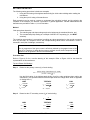
1
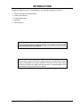
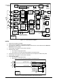
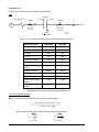
INSTRUCTION MANUAL
FOR
TRANSFORMER DIFFERENTIAL RELAY
BE1-87T
R
BE1-87T
TRANSFORMER DIFFERENTIAL
Style No. D2E A1J D1S0F
Serial No. XXXXXXXXXXXX
PUSH TO
ENERGIZE
OUTPUT
U
P0052-22
R
Publication: 9171300990
Revision: R
09/07
INTRODUCTION
This instruction manual provides information about the operation and installation of the BE1-87T
Transformer Differential relay. To accomplish this, the following information is provided:
• General Information and Specifications
• Controls and Indicators
• Functional Description
• Installation
• Test Procedures
WARNING!
To avoid personal injury or equipment damage, only qualified personnel should
perform the procedures in this manual.
NOTE
Be sure that the relay is hard-wired to earth ground with no smaller than 12 AWG
copper wire attached to the ground terminal on the rear of the unit case. When
the relay is configured in a system with other devices, it is recommended to use a
separate lead to the ground bus from each unit.
9171300990 Rev R
BE1-87T Introduction
i
First Printing: June 1990
Printed in USA
© 1990-1997, 1999-2000, 2003, 2005, 2007 Basler Electric, Highland Illinois 62249 USA
All Rights Reserved
September 2007
CONFIDENTIAL INFORMATION
of Basler Electric, Highland Illinois, USA. It is loaned for confidential use, subject
to return on request, and with the mutual understanding that it will not be used in
any manner detrimental to the interest of Basler Electric.
It is not the intention of this manual to cover all details and variations in equipment, nor does this manual
provide data for every possible contingency regarding installation or operation. The availability and design
of all features and options are subject to modification without notice. Should further information be
required, contact Basler Electric.
BASLER ELECTRIC
ROUTE 143, BOX 269
HIGHLAND IL 62249 USA
http://www.basler.com, [email protected]
PHONE +1 618.654.2341
FAX +1 618.654.2351
ii
BE1-87T Introduction
9171300990 Rev R
REVISION HISTORY
The following information provides a historical summary of the changes made to the BE1-87T instruction
manual (9171300990). Revisions are listed in reverse chronological order.
Manual
Revision and Date
Change
R, 09/07
•
•
•
•
•
Replaced magnetic type targets with electronic type targets.
Updated power supply burden data and output contact ratings.
Updated front panel illustrations to show laser graphics.
Moved content of Section 6, Maintenance to Section 4, Installation.
Added GOST-R certification to Section 1, General Information.
Q, 10/05
•
In Section 1, General Information, Specifications, corrected values for
Maximum Current per Input for 1 Ampere CT Units.
In Section 5, Test Procedures, corrected values inside CAUTION box
for 1 AMP CT on page 5-14.
•
P, 05/03
•
•
•
•
•
•
•
•
N, 09/00
•
•
•
M, 04/99
•
•
•
•
•
•
To delete the part number from the front cover of the manual.
•
•
•
9171300990 Rev R
Corrected Table 1-3 to show power supply ranges.
Changed instruction manual front cover, Figures 4-1, 4-3, and 4-5 to
show new unit case covers.
Changed Figure 4-32 per markup.
Table 3-1 changed mid range nominal volt 125 Vac to 120 Vac.
Corrected Figures 4-24, 4-31a, and A-3
Corrected page 4-38, Step 10; added note to page 4-39, Step 13, and
corrected Steps 14 and 16.
Page A-2, changed 3-Phase fault ratio current to 3-phase fault
current.
Page A-3, corrected formulas for Figure A-3.
Under Section 4, Procedure One, Verify CT Performance, changed
the procedure to the ANSI accuracy class method. This forced
changes in the following steps: 12, 13, 14, 16, 18, 20, and 21.
Under Section 4, Procedure Two, Verify CT Performance, changed
the procedure to the ANSI accuracy class method. This forced
changes in the following steps: 12, 13, 14, and 16.
Added ECO revision information to Table 8-1.
Added Setting Note 7 (ANSI Accuracy Class Method) to Appendix A.
•
L, 05/97
Added a thumbscrew to the figure on the manual front cover.
Added “not all styles” to the Power Supply Output heading on page 34 as well as added “NOTE” and a text box around the second last
paragraph on page 3-4.
Added the new thumbscrew to Figure 4-1 and changed the height
dimensions in Figure 4-2.
Clarified the terminal numbers on Figure 4-6b.
Added a shorting bar between terminals 6 & 7 in Figure 4-11.
Added a shorting bar and normally open contact and normally closed
contact effecting terminals 1, 2, & 5 in Figure 4-12.
Step 13 was corrected on pages 4-31 and 4-39 to include Rw in the
formulas.
Values were changed to Table 5-4 under Option 1-0 for Unrestrained
Trip.
BE1-87T Introduction
iii
Manual
Revision and Date
K, 03/97
Change
•
•
•
•
•
•
•
•
•
•
•
J, 01/96
•
•
•
•
•
I, 01/95
•
•
•
•
•
H, 12/94
•
•
•
•
G, 09/94
•
•
•
•
iv
Deleted all references to Service Manual 9171300620.
Changed the Title of Section 2 from “Controls and Indicators” to
“Human-Machine Interface”.
Replaced the Power Supply Options paragraphs with a new Power
Supply paragraph explaining the new power supply design.
Deleted Figure 3-2 and added Table 3-1, Wide Range Power Supply
Voltage Ranges.
Changed Power Supply Status Output for Type G power supply on
the formerly page 3-6 (now page 3-4) from terminals 9 and 20 to
terminals 9 and 19.
Added information to Section 4 to help the user understand the
procedures better.
Deleted all NOTES FOR USERS OF SENSING INPUT TYPE F
RELAYS and added Section 7, Difference Data.
Changed previous Section 7, Manual Change Information, to Section
8.
Added an Appendix A to clarify the setting procedures.
Added an index to help the user find information easier.
Changed the format of the manual.
Deleted “Difference Data” (formerly Section 7) and included notes for
users of Type F relays.
Moved all information regarding relay settings and checking relay
setting from Section 5, Testing and Setting, to Section 4, Installation.
Section 5 now contains information on test procedures.
Combined 50 and 60 Hz Verification Tests.
Various editorial changes.
Reformatted instruction manual as Windows Help file for electronic
documentation.
Added outline (box) to Figure 5-8 to highlight the figure.
Page 5-42, Step 5, changed, “should be less than 4.45” to, “must be
less than 4.45”.
Added note to page 5-43, Step 10 and corrected the formula in Step
10.
Page 5-45, Step 18, corrected formula and high side results; and
Step 19, changed last sentence from H (13 x tap) to S (21 x tap).
Page 5-46, Steps 20 and 21, corrected figure references.
Page 1-6, changed Specification for Restrained Output, Pickup
Accuracy.
Changed Section 5, Testing and Setting, Verification Tests (all
models): Steps 1, 4, 5, and 8; and Table 5-4.
Page 5-50, Jumper Positions Wye-Delta 1, Step 3: Corrected Input 2
terminal identifications.
Page 5-51, Jumper Positions Delta2-Delta2, Step 2: Corrected
verification statement.
Changed all sections to reflect new Option 1-1.
Added to Section 5 four examples for testing relays to clarify test
procedures.
Added to Section 5 one procedure for setting relays.
Corrected typographical and illustration errors.
BE1-87T Introduction
9171300990 Rev R
Manual
Revision and Date
Change
F, 03/93
•
Changed formula pages 5-4, 5-10, 5-16, and 5-22 from I = the square
root of K over t, to I = K over the square root of t.
E, 01/93
•
Manual was revised to incorporate a revision in the relay that made
sensing input type F obsolete and included the 1 A, 60 hertz and 5 A,
50 hertz model relays.
Section 5, Test Setup, diagrams were changed to clarify relay
connections.
Added three relay Internal Connection diagrams.
Changed unrestrained maximum time to trip, reference old Tables 5-4
and 5-8 (new Tables 5-4, 5-8, 5-12, and 5-16).
Renamed Section 7, Manual Change Information to Section 8,
Manual Change Information and added new Section 7, Difference
Data to support BE1-87T relays with Sensing Input Type F.
•
•
•
•
D, 06/92
•
•
•
C, 03/91
•
•
Manual was revised to include the 1 A, 50 Hz model relay and
reformatted to a new Instruction Manual style.
Additional connection diagrams were included in Section 4 and test
plug information was added to Section 6.
Minor typographical errors were also corrected.
Table 5-1 was expanded and Figure 5-4 Test Setup illustration was
added.
Miscellaneous editing.
B, 03/91
•
Manual (with the exception of Section 2) was rewritten for ease of
use.
A, 06/90
•
•
Figure 3-1 (Functional Block Diagram) corrected.
Formula in caution note (formerly on p. 4-17, now on p. 5-2)
corrected.
Miscellaneous editing.
•
9171300990 Rev R
BE1-87T Introduction
v
This page intentionally left blank.
vi
BE1-87T Introduction
9171300990 Rev R
CONTENTS
SECTION 1 • GENERAL INFORMATION................................................................................................ 1-1
INTRODUCTION................................................................................................................................. 1-1
DESCRIPTION.................................................................................................................................... 1-1
APPLICATION .................................................................................................................................... 1-2
Single-Phase ................................................................................................................................ 1-2
Three-Phase ................................................................................................................................. 1-2
Percentage Restraint.................................................................................................................... 1-2
Second-Harmonic Restraint ......................................................................................................... 1-2
Fifth-Harmonic Restraint............................................................................................................... 1-3
Unrestrained Trip.......................................................................................................................... 1-3
OPTIONS ............................................................................................................................................ 1-3
Push-To-Energize Output Pushbuttons........................................................................................ 1-3
Auxiliary Output Contacts ............................................................................................................. 1-3
Power Supply................................................................................................................................ 1-3
MODEL AND STYLE NUMBER.......................................................................................................... 1-4
Style Number Example................................................................................................................. 1-4
SPECIFICATIONS .............................................................................................................................. 1-5
Current Sensing Inputs................................................................................................................. 1-5
Current Sensing Burden ............................................................................................................... 1-5
Tap Setting Control (Scaling) ....................................................................................................... 1-5
Restrained Output ........................................................................................................................ 1-5
Front Panel Setting %................................................................................................................... 1-6
Unrestrained Output ..................................................................................................................... 1-6
Outputs ......................................................................................................................................... 1-7
Target Indicators........................................................................................................................... 1-7
Harmonic Attenuation ................................................................................................................... 1-7
Timing ........................................................................................................................................... 1-7
Isolation ........................................................................................................................................ 1-9
Power Supply................................................................................................................................ 1-9
Surge Withstand Capability .......................................................................................................... 1-9
Radio Frequency Interference (RFI)............................................................................................. 1-9
UL Recognition ............................................................................................................................. 1-9
GOST-R Certification.................................................................................................................... 1-9
Patent ........................................................................................................................................... 1-9
Shock............................................................................................................................................ 1-9
Vibration........................................................................................................................................ 1-9
Operating Temperature .............................................................................................................. 1-10
Storage Temperature ................................................................................................................. 1-10
Weight......................................................................................................................................... 1-10
Case Size ................................................................................................................................... 1-10
SECTION 2 • CONTROLS AND INDICATORS ....................................................................................... 2-1
LOCATION OF CONTROLS AND INDICATORS............................................................................... 2-1
SECTION 3 • FUNCTIONAL DESCRIPTION........................................................................................... 3-1
GENERAL ........................................................................................................................................... 3-1
DESCRIPTION.................................................................................................................................... 3-1
Current Transformers ................................................................................................................... 3-1
Scaling .......................................................................................................................................... 3-1
Summing....................................................................................................................................... 3-1
30° Internal Phase Shift (Three-Phase Relays ONLY) ................................................................ 3-1
Restrained Trip Output ................................................................................................................. 3-3
Unrestrained Trip Output .............................................................................................................. 3-3
Auxiliary Relay Option .................................................................................................................. 3-4
Power Supply................................................................................................................................ 3-4
Power Supply Status Output (Optional) ....................................................................................... 3-4
Target Indicators (Optional).......................................................................................................... 3-4
% of Trip ....................................................................................................................................... 3-5
9171300990 Rev R
BE1-87T Introduction
vii
SECTION 4 • INSTALLATION.................................................................................................................. 4-1
GENERAL ........................................................................................................................................... 4-1
RELAY OPERATING PRECAUTIONS ............................................................................................... 4-1
MOUNTING......................................................................................................................................... 4-1
DIELECTRIC TEST............................................................................................................................. 4-9
CONNECTIONS.................................................................................................................................. 4-9
RELAY DISASSEMBLY .................................................................................................................... 4-17
Precautions................................................................................................................................. 4-17
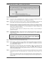
Circuit Board Removal Procedure .............................................................................................. 4-17
DISABLING UNUSED INPUTS......................................................................................................... 4-18
Single-Phase Units ..................................................................................................................... 4-20
Three-Phase Units...................................................................................................................... 4-20
SENSING CONNECTION DIAGRAMS ............................................................................................ 4-20
Single-Phase Input Sensing Connections .................................................................................. 4-20
Three-Phase Input Sensing Connections................................................................................... 4-20
SETTING THE BE1-87T ................................................................................................................... 4-33
Method........................................................................................................................................ 4-33
Procedure One ........................................................................................................................... 4-33
Procedure Two ........................................................................................................................... 4-42
CHECKING THE RELAY SETTINGS AND SYSTEM INPUTS ........................................................ 4-49
MAINTENANCE ................................................................................................................................ 4-50
STORAGE......................................................................................................................................... 4-50
TEST PLUG ...................................................................................................................................... 4-50
SECTION 5 • TEST PROCEDURES ........................................................................................................ 5-1
OVERVIEW ......................................................................................................................................... 5-1
EQUIPMENT REQUIRED................................................................................................................... 5-1
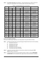
Verification Tests .......................................................................................................................... 5-1
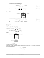
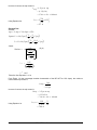
RESTRAINED PICKUP TESTING EXAMPLES ................................................................................. 5-2
Increasing One Input from Balance .............................................................................................. 5-2
Decreasing One Input from Balance ............................................................................................ 5-5
TEST SETUP DIAGRAMS.................................................................................................................. 5-7
VERIFICATION TESTS: 5 AMP CT, 50 OR 60 HZ UNITS ................................................................ 5-9
Restrained Pickup Level Verification ............................................................................................ 5-9
Input (or Tap) Switch Verification ............................................................................................... 5-10
Unrestrained Pickup Verification ................................................................................................ 5-11
Second-Harmonic Restraint Verification .................................................................................... 5-11
Fifth-Harmonic Restraint Verification.......................................................................................... 5-12
Response Time Verification........................................................................................................ 5-13
VERIFICATION TESTS: 1 AMP CT, 50 OR 60 HZ UNITS .............................................................. 5-14
Restrained Pickup Level Verification .......................................................................................... 5-14
Input (or Tap) Switch Verification ............................................................................................... 5-15
Unrestrained Pickup Verification ................................................................................................ 5-16
Second-Harmonic Restraint Verification .................................................................................... 5-16
Fifth-Harmonic Restraint Verification.......................................................................................... 5-17
Response Time Verification........................................................................................................ 5-18
OPERATIONAL TEST PROCEDURES............................................................................................ 5-19
Restrained Pickup....................................................................................................................... 5-19
Unrestrained Pickup ................................................................................................................... 5-19
Second-Harmonic Inhibit ............................................................................................................ 5-19
Fifth-Harmonic Inhibit ................................................................................................................. 5-20
TESTING THREE-PHASE UNITS WITHOUT CHANGING JUMPERS ........................................... 5-20
Jumper Positions Wye-Wye ....................................................................................................... 5-21
Jumper Positions Wye-Delta1 .................................................................................................... 5-21
Jumper Positions Wye-Delta2 .................................................................................................... 5-22
Jumper Positions Delta1-Delta1 ................................................................................................. 5-22
Jumper Positions Delta2-Delta2 ................................................................................................. 5-23
Jumper Positions Delta1-Delta2 ................................................................................................. 5-23
viii
BE1-87T Introduction
9171300990 Rev R
SECTION 6 • DIFFERENCE DATA.......................................................................................................... 6-1
GENERAL ........................................................................................................................................... 6-1
DIFFERENCES................................................................................................................................... 6-1
COMPATIBILITY................................................................................................................................. 6-1
CONNECTIONS.................................................................................................................................. 6-1
APPENDIX A • SETTING NOTES............................................................................................................A-1
INTRODUCTION................................................................................................................................. A-1
SETTING NOTE 1............................................................................................................................... A-1
SETTING NOTE 2............................................................................................................................... A-2
SETTING NOTE 3............................................................................................................................... A-3
SETTING NOTE 4............................................................................................................................... A-4
SETTING NOTE 5............................................................................................................................... A-4
Slope Margin................................................................................................................................. A-4
SETTING NOTE 6............................................................................................................................... A-6
Inrush vs. Unrestraint Tap ............................................................................................................ A-6
SETTING NOT 7 ................................................................................................................................. A-7
CT Performance Evaluation: Saturation Error.............................................................................. A-7
Saturation Factor Defined from the ANSI C Classification........................................................... A-7
Saturation Factor Defined from the CT Excitation Curve ............................................................. A-8
Saturation Factor Definitions Compared ...................................................................................... A-8
Conclusion .................................................................................................................................. A-10
9171300990 Rev R
BE1-87T Introduction
ix
This page intentionally left blank.
x
BE1-87T Introduction
9171300990 Rev R
SECTION 1 • GENERAL INFORMATION
INTRODUCTION
These instructions provide information concerning the operation and installation of BE1-87T Transformer
Differential Relays. To accomplish this, the following is provided:
•
•
•
•
Specifications
Functional characteristics
Mounting information
Setting procedures and examples
WARNING!
To avoid personal injury or equipment damage, only qualified personnel should perform
the procedures presented in these instructions.
These instructions may be used in place of all earlier editions. For change information, see Section 8.
NOTE FOR USERS OF SENSING INPUT TYPE F RELAYS
Users of BE1-87T relays with Sensing Input Type F (three-phases three inputs per
phase) will find Difference Data in Section 6 of this manual that describes features
specific to these relays. The three-phase, three inputs per phase design, previously
available as Sensing Input Type F, has been modified and is now available as Sensing
Input Type G. Due to differences in components and output terminal connections, Type G
relays are not compatible with earlier versions of the BE1-87T with Sensing Input Type F.
There are also differences in the output connections as described in Section 6,
Difference Data.
DESCRIPTION
BE1-87T Transformer Differential Relays provide primary protection for power transformers and are
available in either Single-Phase or Three-Phase configurations. The solid-state BE1-87T compares the
currents entering and leaving the protected transformer. If a fault is detected, the relay initiates a trip
signal to isolate the power transformer. This limits damage to the transformer and minimizes the impact
on the power system.
BE1-87T relays use three types of restraint:
•
•
•
Percentage of through-current
Second harmonic
Fifth harmonic
Selectivity in differential relaying is based on the ability to distinguish between internal and external faults.
This is achieved by comparing the currents into and out of a power transformer. Comparing these
currents often requires more than two inputs. For example:
•
•
Power transformers may have a significant portion (greater than 10 %) of the current flowing in a
third or tertiary winding.
Power transformers can have multiple breakers for a given winding (e.g., ring bus or breakerand-a-half bus).
BE1-87T relays are available with up to five restraint inputs for the single-phase unit and up to three
restraint inputs per phase for the three-phase unit.
9171300990 Rev R
BE1-87T General Information
1-1
APPLICATION
In general, power transformers have different values of current flowing through their primary, secondary,
and tertiary windings. These currents have specific phase relationships depending upon the connections
of the individual windings (e.g., wye/delta). As inputs to a differential relay, these currents must be
compensated or scaled so that the relay can compare the inputs and determine when an unbalance
exists. Under ideal operating conditions, the scaled vector sum of these currents is zero.
Because it is practically impossible to match the magnitudes of these detected currents from the various
power windings using standard CT ratios, the currents are matched within the relay by scaling each of the
applied currents by an appropriate factor called a Tap Setting. This is set by means of the front panel
INPUT dials. By selecting suitable tap ratios, the applied currents are scaled within the relay to achieve
the desired balance for normal operating conditions. BE1-87T relays offer a range of available tap
settings for inputs between 0.4 A to 1.78 A (Sensing Input Range Options 2 and 4 for a 1 A CT) or 2.0 to
8.9 A (Sensing Input Range Options 1 and 3 for a 5 A CT). These settings are independently adjustable in
increments of 0.02 A for Sensing Input Range Options 2 and 4, or 0.1 A for Sensing Input Range Options
1 and 3. These small increments allow more precise scaling of the applied currents and usually eliminate
the need for installing auxiliary ratio-matching CTs.
Single-Phase
BE1-87T Single-Phase relays require phase angle compensation to be accomplished externally by proper
connection of the system CT secondaries. A wye/delta transformer requires that the CT secondaries be
connected in delta for the wye winding and in wye for the delta winding. This type of connection also
eliminates the zero-sequence component of current which could cause a false trip (operation) during
external ground fault conditions on the wye system.
Three-Phase
BE1-87T Three-Phase relays can provide zero-sequence filtering and compensation for phase shifts
introduced by the connections of the power transformer. This 30° Phase Shift compensation (either ±30°
or no compensation) is field selectable. Additionally, this feature allows sharing the transformer differential
relay CTs with other relays or instrumentation.
BE1-87T relays use the highest input current (in per unit values) to operate on maximum restraint. The
relay does not have a conventional operate winding in the internal magnetics. Operating current is
developed within the electronics of the relay.
Percentage Restraint
A primary concern in differential relay applications is security against high current levels caused by faults
outside the protected zone. Inevitable differences in the saturation characteristics between current
transformers require a compensating decrease in relay sensitivity. It is also necessary to be able to adjust
the sensitivity to compensate for transformer voltage taps or CT mismatches. This is accomplished by
providing a restraint factor proportional to the current flowing through the protected zone (throughcurrent).
BE1-87T relays maintain sensitivity at a specified ratio of trip current to through current. This ratio,
generally referred to as slope, is front-panel adjustable in 5 % increments from 15 to 60 %.
Second-Harmonic Restraint
Magnetizing inrush current presents another problem unique to transformer differential relays. Relays
must be capable of detecting the small differences in current caused by the shorting of a limited number
of turns, yet remain secure against the occurrence of magnetizing currents many times the transformer
rating (as seen at one set of terminals).
Although magnetizing inrush is usually associated with the energizing of the transformer, any abrupt
change in the energizing voltage may produce this phenomenon. Common causes are the transients
generated during the onset, evolution and removal of external faults. Desensitizing the relay only during
energization is therefore insufficient.
1-2
BE1-87T General Information
9171300990 Rev R
Magnetizing inrush produces an offset sine wave rich in all harmonics. BE1-87T relays use the second
harmonic to restrain operation because it predominates and because it does not occur in significant
magnitude or duration at other times.
Three-phase BE1-87T relays use second-harmonic sharing. The second-harmonic content of all three
phases is summed together to derive the restraint for each phase. As a result, the second-harmonic
inhibit range and the associated factory setting, is higher than on single-phase relays.
Fifth-Harmonic Restraint
Power transformer overexcitation causes additional exciting current to flow into one set of terminals. This
presents an apparent differential (or operating) current not attributable to an internal fault. Although
potentially damaging, overexcitation is not an internal fault and, therefore, is not an appropriate condition
for transformer differential relay operation. One of the principal components in the complex waveform
produced during overexcitation is the fifth harmonic. BE1-87T relays use fifth-harmonic restraint to inhibit
the differential relay operation.
Unrestrained Trip
Severe internal transformer faults may cause CT saturation. Under such circumstances, harmonicrestraint transformer differential relays may fail to trip because of the extremely high harmonic content in
the waveform. Lack of operation can result in severe transformer damage.
BE1-87T relays provide an independent unrestrained tripping function. When set above the possible
inrush current magnitude, this function provides high-speed protection for the most severe internal faults.
OPTIONS
Push-To-Energize Output Pushbuttons
Two PUSH-TO-ENERGIZE OUTPUT switches are available as a means to verify external output wiring
without the inconvenience of having to test the entire relay. Option 2-S provides a small pushbutton
switch for each isolated output function (Restrained and Unrestrained) and may be actuated by inserting
a thin, non-conducting rod through access holes in the front panel. Refer to Figure 2-1 through 2-4 for
location.
Appropriate power must be applied to Power Supply terminals 3 and 4 (shown in Figures 4-7 through 410) for these pushbuttons to operate the output relays. However, it is not necessary to apply currents to
the sensing inputs of the relay for these switches to function.
Auxiliary Output Contacts
Three types of auxiliary output contacts are available: Normally open, normally closed and SPDT. The
contacts can be made to respond to a restrained trip, an unrestrained trip or both. Refer to the
Functional Description: Auxiliary Relay Option for further information.
Power Supply
Various power supply options are available to allow the BE1-87T to be used with standard supply
voltages. See the Style Number Identification Chart, Figure 1-1, for details.
9171300990 Rev R
BE1-87T General Information
1-3
MODEL AND STYLE NUMBER
The electrical characteristics and operational features of the BE1-87T Transformer Differential Relay are
defined by a combination of letters and numbers that make up its Style Number. The Model Number
together with the Style Number, describe the options included in a specific device and appear on the front
panel, drawout cradle and inside the case assembly.
Upon receipt of a relay, be sure to check the Style Number against the requisition and the packing list to
ensure that they agree.
Style Number Example
The Style Number Identification Chart (Figure 1-1) defines the electrical characteristics and operational
features included in BE1-87T relays. For example, if the Style Number were G1E-A1Y-D1S0F, the device
would have the following:
BE1-87T
Model Number (designates the relay as a Basler Electric, Class 100, Transformer Differential
Relay)
G
Three-phase sensing with three inputs per phase
1
2.0 to 8.9 A Sensing Range at 60 Hz
E
One unrestrained output contact and one restrained output contact
A1
No intentional delay in the outputs
Y
48/125 Vdc switchable
D
Current operated targets
1
Percent IOP display and high-speed trip
S
Push-to-Energize outputs
0
No auxiliary output
F
Semi-flush mounting
Figure 1-1. Style Number Identification Chart
1-4
BE1-87T General Information
9171300990 Rev R
SPECIFICATIONS
The BE1-87T relay is available in either single-phase or three-phase configurations and with the following
features and capabilities.
Current Sensing Inputs
The unit is designed to operate from the secondary of current
transformers rated at either 1 A or 5 A. Frequency range is ±5 Hz of
nominal.
Maximum Current Per Input
1 Ampere CT Units
4 A continuous; 50 A or 50 X tap (whichever is less) for 1 second.
5 Ampere CT Units
20 A continuous; 250 A or 50 X tap (whichever is less) for 1
second.
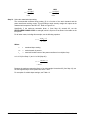
For ratings other than one second, the rating may be calculated as:
K
I=
t
Where:
t is the time (in seconds) that the current flows
K = 50 A or 50 X tap, whichever is less (1 Amp CT Units), or
K = 250 A or 50 X tap, whichever is less (5 Amp CT Models)
Current Sensing Burden
Less than 0.02 ohm per phase.
Tap Setting Control (Scaling)
Front panel rotary switches, labeled INPUT, permit scaling the
sensed input current (or tap setting) over the range of:
1 Ampere CT Units
0 . 4 to 1 . 78 in 0 . 02 A increments.
5 Ampere CT Units
2 . 0 to 8 . 9 A, in 0 . 1 A increments.
Restrained Output
Pickup Range
Front panel thumbwheel switches adjust pickup of the restrained
output as a percentage of the through current. The range is 15 to
60 % of the operating current in 5 % increments.
Pickup Accuracy
±6 % of pickup ±100 mA (5 Ampere Units) or ±20 mA (1 Ampere
units).
Minimum Pickup
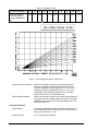
0.35 ±6 % of tap setting. Refer to Table 1-1 and Figure 1-2. Table
1-1 provides calculated intersection points of the slope
characteristic and the minimum pickup (in multiples of tap) as
shown in Figure 1-2. The calculation was derived from the formula:
Maximum I Restraint =
Minimum Pickup
Percent of Slope
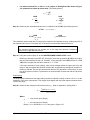
For example:
Minimum Pickup 0.35
= 1.75
=
Percent of Slope 20 %
The relay operates when the per unit difference current (operating
current) is above the 0.35 pu or the slope line in Figure 1-2.
Calculation examples are found in Section 5.
9171300990 Rev R
BE1-87T General Information
1-5
Table 1-1. Multiples of Tap
Front Panel Setting %
Maximum Restraint
Current At Minimum
Pickup In Multiples of
Tap
15
20
25
30
35
40
45
50
55
60
2.33
1.75
1.40
1.17
1.00
0.875
0.778
0.700
0.636
0.583
Figure 1-2. Percentage Restraint Characteristic
Second-Harmonic Restraint
Inhibit of the restrained output occurs when the secondharmonic component exceeds a pickup setting, which is
internally adjustable over the range of 8 % to 15 % of the
operating current for single-phase Units or 11 to 27 % for
three-phase units. The factory setting is 12 % for singlephase units and 18 % for three-phase units.
Fifth-Harmonic Restraint
Inhibit of the restrained output occurs when the fifth-harmonic
component exceeds a pickup setting which has an internally
adjustable range of 25 to 45 % of the operating current. The
factory setting is 35 %.
Unrestrained Output
1-6
Pickup Range
Front panel thumbwheel switches adjust the pickup point of
the unrestrained output over a range of 6 to 21 times the tap
setting in increments of 1 x Tap.
Pickup Accuracy
±3 % of the front panel setting.
BE1-87T General Information
9171300990 Rev R
Outputs
Output contacts are rated as follows.
Resistive
120/240 Vac
Make 30 A for 0.2 seconds, carry 7 A continuously and break
7 A.
250 Vdc
Make and carry 30 A for 0.2 seconds, carry 7 A continuously
and break 0.3 A.
500 Vdc
Make and carry 15 A for 0.2 seconds, carry 7 A continuously
and break 0.1 A.
Inductive
120/240 Vac, 125/250 Vdc
Target Indicators
Make and carry 30 A for 0.2 seconds, carry 7 A continuously
and break 0.3 A, (L/R = 0.04).
Target indicators may be either internally-operated or currentoperated (operated by a minimum of 0.2 A through the output
trip circuit). When the target is current-operated, the
associated output circuit must be limited to 30 A for 0.2
seconds, 7 A for 2 minutes and 3 A continuously.
Single-Phase Units
Either an internally-operated or a current-operated target is
supplied (as selected by the Style Number) for each trip
output (i.e., the restrained and the unrestrained functions).
Three-Phase Units
Either internally operated or current operated targets (as
selected) indicate the function (restrained or unrestrained)
that caused the trip, and the tripped phase (A, B, C).
Harmonic Attenuation
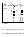
Refer to Table 1-2.
Table 1-2. Harmonic Attenuation
Parameter
(50 Or 60 Hz Models)
Minimum Attenuation at Indicated Fundamental
50/60 Hz
100/120 Hz
150/180 Hz
250/300 Hz
500 Hz
Through Current
0
0
0
0
12 dB
Operating Current
0
0
0
0
12 dB
2nd Harmonic Restraint
12 dB
0
12 dB
12 dB
12 dB
5th Harmonic Restraint
12 dB
12 dB
12 dB
0
12 dB
Timing
(For 60 Hz units only)
9171300990 Rev R
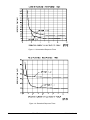
Refer to Figure 1-3 for Unrestrained Response Times and
Figure 1-4 for Restrained Response Times.
BE1-87T General Information
1-7
Figure 1-3. Unrestrained Response Times
Figure 1-4. Restrained Response Times
1-8
BE1-87T General Information
9171300990 Rev R
In accordance with IEC 255-5 and ANSI/IEEE C37.90-1989,
one minute dielectric (high potential) tests, as follows:
Isolation
All circuits to ground: 2121 Vdc
Input to output circuits: 1500 Vac or 2121 Vdc
Refer to Table 1-3.
Power Supply
Table 1-3. Power Supply Specifications
Nominal Input
Voltage
Input Voltage
Range
Burden at
Nominal
(Energized)
Burden at
Nominal
(De-energized)
J (Mid
Range)
125 Vdc
62 – 150 Vdc
9.0 W
6.4 W
120 Vac
90 – 132 Vac
21.0 VA∗
19.8 VA
K (Mid
Range)
48 Vdc
24 - 60 Vdc
8.5 W
6.2 W
L† (Low
Range)
24 Vdc
12 - 32 Vdc
9.0 W
6.4 W
Y (Mid
Range)
48 Vdc
24 - 60 Vdc
8.5 W
6.2 W
125 Vdc
62 – 150 Vdc
9.0 W
6.4 W
250 Vdc
140 – 280 Vdc
9.5 W
6.4 W
240 Vac
190 – 270 Vac
28.0 VA*
26.0 VA
Type
Z (High
Range)
∗
At 55 - 65 Hz.
†
Type L power supply may require 14 Vdc to begin operation. Once
operating, the voltage may be reduced to 12 Vdc.
Surge Withstand Capability
Qualified to ANSI/IEEE C37.90.1-1989, Standard Surge
Withstand Capability (SWC) Tests for Protective Relays and
Relay Systems, and IEC 255-5 Impulse Test and Dielectric
Test.
Radio Frequency Interference
(RFI)
Maintains proper operation when tested in accordance with
IEEE C37.90.2-1987, Trial-Use Standard Withstand
Capability of Relay Systems to Radiated Electromagnetic
Interference from Transceivers.
UL Recognition
UL Recognized per Standard 508, UL File No. E97033. Note:
Output contacts are not UL Recognized for voltages greater
than 250 V.
GOST-R Certification
Gost-R certified, No. POCC US.ME05.B03391; complies with
the relevant standards of Gosstandart of Russia. Issued by
accredited certification body POCC RU.0001.11ME05.
Patent
Patented in U.S., 1991, U.S. Patent No. 5014153.
Patented in Canada, 1993.
Shock
In standard tests, the relay has withstood 15 g in each of
three mutually perpendicular axes without structural damage
or degradation of performance.
Vibration
In standard tests, the relay has withstood 2 g in each of three
mutually perpendicular axes swept over the range of 10 to
500 Hz for a total of six sweeps, 15 minutes each sweep,
without structural damage or degradation of performance.
9171300990 Rev R
BE1-87T General Information
1-9
Operating Temperature
-40°C (-40°F) to 70°C (158°F)
Storage Temperature
-65°C (-85°F) to 100°C (212°F)
Weight
22.3 lbs (10.1 kg) maximum (three-phase unit)
19.5 lbs (8.85 kg) maximum (single-phase unit)
Case Size
1-10
All units are supplied in an M1 case size. See Section 4,
Installation for case dimensions.
BE1-87T General Information
9171300990 Rev R
SECTION 2 • CONTROLS AND INDICATORS
LOCATION OF CONTROLS AND INDICATORS
Table 2-1 lists and briefly describes the operator controls and indicators of the BE1-87T Transformer
Differential Relay. Reference the call-out letters A through M to Figures 2-1 to 2-3; N through Q to Figure
2-5. Exploded views of controls that are mounted inside the relay (call-out letters B, D and I) are shown in
Figure 2-4.
Table 2-1. Controls and Indicators
Letter
A
Control or Indicator
INPUT (or TAP) Switches
Function
Front panel INPUT switches are used to scale the
transformer currents. There are two of these rotary
switches for each input.
1 Ampere CT Units
Each of the upper switches is calibrated to represent
the tenths and units digits (0.4 through 1.6) of tap
value. Each of the lower switches is calibrated to
represent two-hundredths of tap value for each
increment. Always add the setting of the lower switch to
that of the upper switch. For example, if a setting of
1.02 is desired, the upper switch must be at 1.0 and the
lower switch must be at 0.02. The total setting range for
each input is 0.4 to 1.78.
5 Ampere CT Units
Each of the upper switches is calibrated to represent
the units digit (2 through 8) of tap value. Each of the
lower switches is calibrated to represent tenths of tap
value. Always add the setting of the lower switch to that
of the upper switch. For example, if a setting of 5.0 is
desired, the upper switch is set to 5.0, the lower switch
must be at 0.0. The total setting range for each input is
2.0 to 8.9.
B
30° Phase Shift Jumpers
(three-phase units ONLY)
These jumpers control the internal phase shift of the
relay, either +30°, -30°, or 0°, depending upon the
position of the jumpers provided for each input on the
Analog #2 Board, shown in Figure 2-4. Additional
information is in Section 4.
C
UNRESTRAINED PICKUP
LEVEL Switches
This thumbwheel switch establishes the desired pickup
setting for all phases of the unrestrained output. The
adjustment range is from 6 to 21 times the phase tap
setting, in increments of 1.
D
CALIBRATE Switch
(three-phase units ONLY)
A two-position switch is located on each Analog #1
Board and is easily accessible on the right side of the
relay when it is withdrawn from the case. In the
CALIBRATE position, these switches inhibit the
harmonic share feature when calibrating the 2nd
Harmonic Restraint. In the NORMAL position, the relay
will operate normally.
E
POWER Indicator
This LED will illuminate when operating power is
supplied to the internal circuitry of the relay.
9171300990 Rev R
BE1-87T Controls and Indicators
2-1
Letter
F
Control or Indicator
PUSH-TO-ENERGIZE
OUTPUT Switches Option
Function
Two momentary pushbutton switches are accessible by
inserting a 1/8 inch diameter non-conducting rod
through access holes in the front panel. Switch R,
when actuated, closes the Restrained Output Relay
contacts. Switch U, when actuated, closes the
Unrestrained Output Relay contact(s).
NOTE
The optional Auxiliary Relay contacts
(Option 3-1, 3-2 or 3-5) will also be
operated by the PUSH-TO-ENERGIZE
switches if enabled by the two internal
Auxiliary Relay Control Switches.
(Refer to LETTER I.)
G
FUNCTION Targets Option
Electronically-latched LED targets that indicate an
unrestrained or restrained output has occurred.
H
Target Reset Switch
Resets the electronically-latched targets.
I
Auxiliary Relay Control
Switches Option
Two internal slide switches, S1 and S2, enable the
optional Auxiliary Output Relay to close only when a
restrained output occurs (S1 ON), only when an
unrestrained output occurs (S2 ON), or to close when
either output occurs (S1 and S2 ON).
When shipped from the factory, the Auxiliary Relay will
be configured with S1 and S2 ON.
NOTE
The switches are located on the
mother board and are only accessible
by withdrawing the relay case.
J
ELEMENT Targets Option
(three-phase units ONLY)
Electronically-latching LED targets indicate the phase
that caused a trip operation.
K
RESTRAINED PICKUP
LEVEL Switches
Thumb-wheel switches (one per phase element) are
used to adjust the desired percent of allowable
through-current restraint from 15 to 60 % in 5 %
increments. (Through-current is the greatest relative
individual input current.)
The through-current restraint characteristic is
individually adjustable for phases A, B, and C.
In a three-phase unit, all three switches are typically
kept at identical settings.
2-2
L
UNREST. TRIP Indicator
Red LED lights when there is an unrestrained pickup.
M
REST. TRIP Indicator
Red LED lights when there is a restrained pickup.
N
M Indicator
Red LED lights when the % OF TRIP pushbutton P is
pressed and the restraint current is below the slope
characteristic kneepoint as defined in Table 1-1. That
is, the relay will operate at minimum pickup (0.35 times
tap).
BE1-87T Controls and Indicators
9171300990 Rev R
Letter
Control or Indicator
Function
O
S Indicator
Red LED lights when the % OF TRIP pushbutton P is
pressed and the restraint current is above the slope
characteristic kneepoint as defined in Table 1-1. That
is, the relay will operate based on the restraint
characteristic.
P
Percent of Trip Pushbutton
Pushbutton that is used to activate the % of TRIP
LEDs.
Q
% OF TRIP Indicators Option
When the % OF TRIP pushbutton P is pushed, eight
LEDs, shown in Figure 2-5, are used to indicate the
approximate percentage of operating current to:
Minimum pickup (LED M also lights); or
Slope characteristic pickup (LED S also lights).
The eight LEDs represent the following approximate
percentages.
1 LED:
3% (Yellow LED)
2 LEDs: 7% (Yellow LED)
3 LEDs: 11% (Yellow LED)
4 LEDs: 20% (Red LED)
5 LEDs: 40% (Red LED)
6 LEDs: 60% (Red LED)
7 LEDs: 80% (Red LED)
8 LEDs: 100% (Red LED)
A bar chart above the LEDs shows the relative
percentage of trip.
9171300990 Rev R
BE1-87T Controls and Indicators
2-3
INPUT 1
1.00
INPUT 2
1.60
0.40
B
0.06
See Fig. 2-4
1.00
1.60
0.06
1.60
SET
X TAP
A
B
6
7
C
8
D
E
10
F
G
11
12
H
J
13
14
K
L
15
16
M
17
18
0.40
0.40
0.12
INPUT 3
1.00
0.12
0.06
0.12
A
9
N
P
0.00
0.18
0.00
0.18
0.00
0.18
C
19
20
R
S
21
UNRESTRAINED PICKUP LEVEL
REST.
TRIP
UNREST.
TRIP
M
REST.
TRIP
REST.
TRIP
L
UNREST.
TRIP
UNREST.
TRIP
RESTRAINED PICKUP LEVEL
PHASE A
SET
A
B
PHASE B
15
C
20
25
D
30
E
F
35
G
H
PHASE C
% THRU
CURRENT
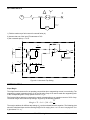
J
K
BE1-87T
TRANSFORMER DIFFERENTIAL
Style No. G4E A1J D0S0F
Serial No. XXXXXXXXXXXX
40
45
50
55
60
D
See Fig. 2-4
E
POWER
R
K
J
F
G
PUSH TO
ENERGIZE
OUTPUT
I
See Fig. 2-4
A
B
C
R
U
P0052-24
H
ELEMENT
FUNCTION
U.S. PATENT 5,014,153
PATENTED IN CANADA, 1993
Figure 2-1. Sensing Input Range 1 or 3 Three-Phase, Three Inputs
2-4
BE1-87T Controls and Indicators
9171300990 Rev R
INPUT 1
1.00
INPUT 2
1.60
1.00
INPUT 3
1.60
1.00
INPUT 4
1.60
1.00
INPUT 5
1.60
1.00
1.60
A
0.40
0.40
0.40
0.40
0.40
0.06
0.12
0.06
0.12
0.06
0.12
0.06
0.12
0.06
0.12
0.00
0.18
0.00
0.18
0.00
0.18
0.00
0.18
0.00
0.18
SETTING
A
B
C
D
E
X TAP
6
7
8
9
10 11 12 13 14 15 16 17 18 19 20 21
F
G
H
J
K
L
M
N
P
R
S
C
UNRESTRAINED PICKUP LEVEL
REST.
TRIP
UNREST.
TRIP
RESTRAINED PICKUP LEVEL
M
SETTING
A
% THRU CURRENT
L
B
C
D
E
F
G
H
J
BE1-87T
TRANSFORMER DIFFERENTIAL
Style No. D4E A1J D0S5F
Serial No. XXXXXXXXXXXX
K
K
15 20 25 30 35 40 45 50 55 60
E
POWER
R
F
G
PUSH TO
ENERGIZE
OUTPUT
I
See Fig. 2-4
R
U
P0052-23
H
FUNCTION
U.S. PATENT 5,014,153
PATENTED IN CANADA, 1993
Figure 2-2. Sensing Input Range 1 or 3, Single-Phase, Five Inputs
9171300990 Rev R
BE1-87T Controls and Indicators
2-5
INPUT 1
1.00
1.60
0.40
B
1.60
SET
X TAP
A
B
6
7
C
8
D
E
10
F
G
11
12
H
J
13
14
K
L
15
16
M
17
18
0.40
0.06
See Fig. 2-4
INPUT 2
1.00
0.12
0.12
0.06
A
9
N
P
0.18
0.00
0.00
0.18
C
19
20
R
S
21
UNRESTRAINED PICKUP LEVEL
UNREST.
TRIP
REST.
TRIP
M
UNREST.
TRIP
REST.
TRIP
UNREST.
TRIP
REST.
TRIP
L
RESTRAINED PICKUP LEVEL
PHASE A
SET
A
B
PHASE B
15
C
20
25
D
30
E
F
35
G
H
PHASE C
% THRU
CURRENT
J
K
BE1-87T
TRANSFORMER DIFFERENTIAL
Style No. E2E A1J D0S0F
Serial No. XXXXXXXXXXXX
40
45
50
55
60
D
See Fig. 2-4
E
POWER
R
K
J
F
G
PUSH TO
ENERGIZE
OUTPUT
I
See Fig. 2-4
A
B
C
R
U
P0052-25
H
ELEMENT
FUNCTION
U.S. PATENT 5,014,153
PATENTED IN CANADA, 1993
Figure 2-3. Sensing Input Range 2 or 4 Three-Phase, Two Inputs
2-6
BE1-87T Controls and Indicators
9171300990 Rev R
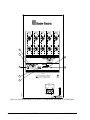
LH EDGE OF ANALOG #2
BOARD (THE 4TH BOARD
DOWN, COUNTING THE
MAGNETIC BOARD.)
BE1-87T
VR2
TP+12V
C1
J1
IN
1
0C
0A
Δ1
Δ2
WYE
0B
J2
IN
2
Δ1
Δ2
WYE
IN
3
Δ1
Δ2
WYE
J9
J10
AR
P0052-26
J11
D
B
2
S2
P6
AUX
UNRES
J2
SECTION OF THE (VERTICAL)
MOTHER BOARD AT LEFT
REAR OF RELAY
ON
CR19
AUX RES
CR7
I
S1
42
Figure 2-4. Controls Mounted Inside the Relay
9171300990 Rev R
BE1-87T Controls and Indicators
2-7
K
L
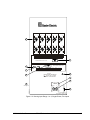
Q
M
P
N
R
BE1-87T
TRANSFORMER DIFFERENTIAL
Style No. D3E A1J D1S0F
Serial No. XXXXXXXXXXXX
O
PUSH TO
ENERGIZE
OUTPUT
U
P0052-27
R
Figure 2-5. Sensing Input Range 2 or 4, Option 1-1, Single-Phase, Five Inputs, % OF TRIP Option
2-8
BE1-87T Controls and Indicators
9171300990 Rev R
SECTION 3 • FUNCTIONAL DESCRIPTION
GENERAL
BE1-87T relays are solid-state devices that protect transformers by providing output contact closure when
the scaled current into the protected transformer does not equal the scaled current out, within defined
limits. These relays are harmonically restrained to prevent tripping during initial energization and external
fault conditions. A through-current restraint also provides security against tripping for external faults. An
unrestrained tripping element is included to provide a high-speed trip in the event of a particularly severe
fault within the transformer.
DESCRIPTION
The functional block diagrams of Figures 3-1 and 3-2 illustrate the overall operation of the BE1-87T
Transformer Differential Relay. (Figure 3-1 shows Phase A or single-phase functions; Figure 3-2 shows
the additional functions for phases B and C.) Since the three phases are functionally similar, only phase A
is shown in detail in Figure 3-1. Note that in a three-phase unit, there may be one restrained output for
each phase (Output Type Option E in the third position of the Style Number), or one restrained output that
serves for all three phases (Option F in the third position). When Target Option C or D is specified for a
three-phase Unit (in the seventh position), an individual target is supplied for each phase.
Current Transformers
In the protected zone of the power system, CTs with a 1 ampere or 5 ampere secondary winding supply
the sensing current for each input. This is not shown in Figure 3-1 or Figure 3-2. Other relays may be
connected ahead of the BE1-87T. Sensing currents are, in turn, applied to relay internal input
transformers. These transformers provide system isolation.
Scaling
Input currents are scaled by the front panel INPUT rotary switches that introduce resistances to the
internal CT secondaries. The switches are calibrated in 0.02 ampere increments from 0.4 to 1.78 ampere
for 1 ampere CT units (Options 2 or 4 in the second position of the Style Number), and in 0.1 ampere
increments from 2.0 to 8.9 amperes for 5 ampere CT models (Options 1 or 3 in the second). The many
graduations of adjustment are provided to allow each input to approach an ideal representation of the
actual operating per unit value.
Summing
Analog signals representing each input contribution are vector summed (shown as Summing in Figure 31). This summing process produces the operating current (IOP) that is the phasor sum of the input
currents.
Ideally, and with perfectly matched CTs, a transformer without an internal fault should cause IOP to be
exactly zero on a continuous basis. When not zero, a fault would be indicated. However, saturation
effects caused by heavy through-current or magnetic inrush can cause a temporary imbalance even
though no internal fault has occurred. To prevent a false trip under such conditions, various types of
restraint are used. Each restraint is specific to a potential cause of misoperation. These are individually
discussed in the topic Restrained Trip Output.
30° Internal Phase Shift (Three-Phase Relays ONLY)
For three-phase units, the inputs to the Summing function are first routed through the 30° Phase Shift
circuit. There the signals may be advanced or retarded by 30° or passed through unchanged.
Compensating phase shift direction (shown as the Phase Shift Setting circuit in Figure 3-1) is determined
by the position of three jumpers on the internal Analog #2 Board. (The location of these jumpers is shown
in Figure 2-4.) The internal phase shift will accomplish the corresponding zero sequence blocking. The
current magnitude will be increased by 3 and must be taken into account in the tap setting (explained
later in detail in Section 4).
9171300990 Rev R
BE1-87T Functional Description
3-1
OPERATING
POWER
POWER
SUPPLY
1
0 SHIFT SETTING:
+30°, -30 °, 0 °
TO INTERNAL
CIRCUITRY
POWER
SUPPLY
SENSOR
POWER
% I max
I max
SCALING
( TAP)
IN. 1,0 B SCALE
IN. 1, 0 C SCALE
30 ° 0
SHIFT
(ONLY ON
30 UNITS)
IN. 2
SCALING
( TAP)
IN. 2, 0B SCALE
IN. 2, 0C SCALE
30 ° 0
SHIFT
(ONLY ON
30 UNITS)
IN. 3
SCALING
( TAP)
IN. 3, 0 B SCALE
IN. 3, 0 C SCALE
IN. 1
0A
OR
10
2
IN. 4
SCALING
( TAP)
2
IN. 5
SCALING
( TAP)
COM.
UNREST
TRIP
(6 TO 21
TIMES TAP)
CALCULATE
MAXIMUM
INDIVIDUAL
CURRENT
30 ° 0
SHIFT
(ONLY ON
30 UNITS)
SUMMING:
ALGEBRAIC
SUM OF
INPUTS =
OPERATING
CURRENT
( Iop )
FIFTH
HARMONIC
RESTRAINT
FILTERS
I op
6
SECOND
HARMONIC
RESTRAINT
FILTERS
UNREST. SETTING
POWER
SUPPLY
STATUS
REST.
PICKUP
T
CONTROL
Iop
8
LEDs
% OF
TRIP
% I max
RESTRAINED
IF Iop
5
>% Imax
THEN TRIP
0B
TARGET
0C
REST.
5TH >
TRIP
S1
SETTING
=INHIBIT
3
OR
2ND >
SETTING
=INHIBIT
AUX.
OPTION
S2
3
IF I op >
UNREST. UNRESTRAINED
SETTING
0B
THEN TRIP
0C
TARGET
UNREST
TRIP
TO OTHER PHASES
(THREE-PHASE ONLY)
OR TARGET
BE1-87T
D741-001a
7-11-94
4
Figure 3-1. Functional Block Diagram
NOTES
1
2
3
4
5
6
7
8
Present in three-phase units ONLY.
Inputs 4 and 5 are available in single-phase units ONLY.
The settings are calibrated to a specified percentage of the harmonic to the fundamental. See Harmonic
Restraints for factory settings.
Phase Targets are supplied on three-phase units ONLY.
Restrained Trip Contact:
•
One contact for single-phase units.
•
One contact or one contact per phase available on three-phase units.
Three-phase units use the sum of the second harmonic from each phase to restrain each phase.
Phase Targets are supplied on three-phase units ONLY.
Restrained Trip Contact:
•
One contact for single-phase units.
•
One contact or one contact per phase available on three-phase units.
0B
0C
IN. 1
IN. 2
IN. 3
COM.
0 B SAME AS 0 A
RESTRAINED
OR
UNRESTRAINED
IN. 1
IN. 2
IN. 3
COM.
0 C SAME AS 0 A
4
RESTRAINED
OR
UNRESTRAINED
BE1-87T
D741-001b
7-11-94
TARGET
0B
TARGET
0C
OPTIONAL
RESTRAINED
CONTACTS
FOR EACH OF
3 PHASES
(SEE NOTE 5
0B
0C
Figure 3-2. Functional Block Diagram, Phase B and Phase C
3-2
BE1-87T Functional Description
9171300990 Rev R
Restrained Trip Output
Restrained trip output contacts are subject to three types of restraint (i.e., inhibit) signals:
•
•
•
Percentage restraint
Second-harmonic restraint
Fifth-harmonic restraint
These signals are developed within the relay in response to external conditions and block the restrained
output contacts from closing.
Percentage Restraint
Percentage restraint developed from the maximum through current and the slope setting determines the
minimum operating current IOP (Figure 3-1) in a comparator where IOP must be greater than %IMAX to
produce a Restraint Trip output. The IOP desired trip level is adjustable on the front panel RESTRAINED
PICKUP LEVEL switches shown in Figures 2-1 through 2-3.
Comparators in the Calculate Max. Individual Current circuit determine which input (of a particular phase)
is receiving the greatest current. That input is chosen and then called the IMAX signal. The IMAX output is
then scaled by the front panel RESTRAINED PICKUP LEVEL switches (shown as the Restrained Pickup
Control in Figure 3-1). The resulting signal (%IMAX ), that represents the percentage of through-current is
extended to the Then Trip comparator and the IOP Divided By %IMAX function.
The Then Trip circuitry compares the operating current (IOP) to %IMAX. If the operating current is greater
than %IMAX (and there is no 5th or 2nd harmonic restraint to cause an inhibit as described below), a
Restrained Trip output is produced.
IOP Divided By %IMAX contains eight comparators and compares IOP to the preset percentage levels of
%IMAX. If IOP is greater than the preset percent of %IMAX for a specific comparator, the LED associated with
that comparator lights. The eight LEDs represent the following approximate percentages:
First LED:
Second LED:
Third LED:
Fourth LED:
Fifth LED:
Sixth LED:
Seventh LED:
Eighth LED:
3%
7%
11%
20%
40%
60%
80%
100%
NOTE
As each successive LED lights, all previous or lesser percentage value LEDs will also
light.
Harmonic Restraints
Development of a restrained trip output may be inhibited by either of two harmonic restraints. These are
generated by bandpass filters tuned to the second and fifth harmonics of the operating current.
Comparators monitor these signals. When the fifth-harmonic content exceeds 35% of the operate current
(indicating overexcitation of the transformer) or when the second-harmonic content exceeds 12% (singlephase) or 18% (three-phase) of the operate current (indicating a magnetic inrush condition), an inhibit
signal is developed that blocks operation of the Restrained Trip output contact. (Stated percentages
represent the factory setting.)
Unrestrained Trip Output
IOP is also compared against a reference established by the front panel UNRESTRAINED PICKUP
LEVEL switch is shown in Figures 2-1 through 2-5. When this reference is exceeded, the Unrestrained
Trip output relay is energized. An unrestrained trip is not affected by through-current or harmonic inhibits.
9171300990 Rev R
BE1-87T Functional Description
3-3
Auxiliary Relay Option
Auxiliary relays (Option 3-1, 3-2 or 3-5 in the tenth position of the Style Number) are accompanied by two
switches, S1 and S2, which allow the relays to respond to a restrained trip (S1 ON) or to an unrestrained
trip (S2 ON), or both (S1 and S2 ON). These switches (letter I of Figure 2-4 and described in Table 2-1)
are located on the mother board and are shipped in the ON position. Auxiliary relays may be disabled by
opening both switches (S1 and S2 OFF).
Power Supply
Relay operating power is developed by a wide-range, isolated, low-burden, switching power supply that
delivers ±12 Vdc to the relay’s internal circuitry. The power supply is not sensitive to the input power
polarity. A front panel LED power indicator lights to indicate that the power supply is functioning properly.
Style number designations and input voltage ranges for the available power supply models are provided
in Section 1, General Information.
Power Supply Status Output (Optional)
The Power Supply Status output relay has normally closed (NC) contacts. The relay is energized by the
presence of nominal voltage at the output of the power supply. Normal operating voltage then keeps the
relay continuously energized and its contacts open. However, if the power supply voltage falls below
requirements, the Power Supply Status output relay will de-energize and close the contacts.
The Power Supply Status output is not associated with any magnetically latched target. The POWER LED
on the front panel provides a visual indication of the normal operating status of the power supply.
NOTE
Sensing Input Types A through E (first position of the Style Number) have paddle-operated
shorting bars included in the relay case (terminals 19 and 20) so that the Power Supply
Status output terminals can provide a remote indication that the BE1-87T has been
withdrawn from its case or that it has been taken out of service by removing the connection
plugs. Sensing Input Type G relays do NOT have shorting bars on the Power Supply
Status output. Sensing Input Type G units use terminal 9 (lower terminal block) and
terminal 19 (upper terminal block) for the Power Supply Status output.
Target Indicators (Optional)
When the Target option is specified as either C or D, shown in the seventh position of the Style Number,
electronically latched indicators, labeled FUNCTION, are incorporated in the front panel. The
electronically latched and reset targets consist of red LED indicators. The appropriate target is tripped
when either a restrained (R) or unrestrained (U) output occurs. Latched targets are reset by operating the
target reset switch on the front panel. If relay operating power is lost, any illuminated (latched) targets are
extinguished. When relay operating power is restored, the previously latched targets are restored to their
latched state.
When targets are specified for three-phase relays, three additional ELEMENT targets are incorporated to
indicate the phase involved. Only the FUNCTION targets, restrained (R) or unrestrained (U) are available
for single-phase units.
Relays can be equipped with either internally operated targets (Type C) or current operated targets (Type
D). Both target types are reset by operating the target reset switch.
• Type C target (referred to as internally operated) is actuated by an integral driver circuit that responds
directly to the relay internal logic. This type of target is tripped regardless of the amount of current
flowing through the associated output contact.
• Type D target (referred to as current operated) is actuated when a minimum of 0.2 A flows through
the associated output contacts. To accomplish this, a special reed relay is placed in series with the
contact to signal the target indicator. (The series impedance of the reed relay is less than 0.1 ohm.)
Current in the output circuit must be limited to 30 amperes for 0.2 seconds, 7 amperes for 2 minutes
and 3 amperes continuously.
3-4
BE1-87T Functional Description
9171300990 Rev R
NOTE
Prior to September 2007, the BE1-87T target indicators consisted of magnetically
latched, disc indicators. These mechanically latched target indicators have been
replaced by the electronically latched LED targets in use today.
% of Trip
When the % of trip pushbutton Q is pushed, eight LEDs, shown in Figure 2-5, are used to indicate the
percentage of operating current to: Minimum pickup (LED M also lights); or Slope characteristic pickup
(LED S also lights). The eight LEDs represent the following percentages:
1 LED:
3% (Yellow LED)
2 LEDs: 7% (Yellow LED)
3 LEDs: 11% (Yellow LED)
4 LEDs: 20% (Red LED)
5 LEDs: 40% (Red LED)
6 LEDs: 60% (Red LED)
7 LEDs: 80% (Red LED)
8 LEDs: 100% (Red LED)
A bar chart above the LEDs shows the relative percentage of trip.
9171300990 Rev R
BE1-87T Functional Description
3-5
This page intentionally left blank.
3-6
BE1-87T Functional Description
9171300990 Rev R
SECTION 4 • INSTALLATION
GENERAL
When not shipped as part of a control or a switchgear panel, the relay is shipped in a sturdy carton to
prevent damage during transit. Immediately upon receipt of a relay, check the model and Style Number
against the requisition and packing list to see that they agree. Visually inspect the relay for damage that
may have occurred during shipment. If there is evidence of damage, immediately file a claim with the
carrier and notify the Regional Sales Office, or contact a sales representative at Basler Electric, Highland,
Illinois.
In the event the relay is not to be installed immediately, store the relay in its original shipping carton in a
moisture- and dust-free environment. For more information, see STORAGE in Section 4. When the relay
is to be placed in service, it is recommended that the VERIFICATION TESTS, shown in Section 5, be
performed prior to installation.
RELAY OPERATING PRECAUTIONS
Before installation or operation of the relay, note the following precautions.
1. A minimum of 0.2 A in the output circuit is required to ensure operation of current-operated
targets.
2. The relay is a solid-state device and has been type tested in accordance with the requirements
defined under Dielectric Test. If a wiring insulation test is required on the panel assembly in
which the relay is to be installed, it is suggested that the connection plugs (or paddles) of the
relay be removed and the cradle withdrawn from the case so as not to produce false readings
during the wiring insulation test.
3. When the connection plugs are removed, the relay is disconnected from the operating circuit
and will not provide system protection. Always be sure that external operating (monitored)
conditions are stable before removing a relay for inspection, testing, or servicing. Be sure that
connection plugs are in place before replacing the front cover.
CAUTION
To prevent possible false tripping, the upper connection plug should be in place prior to
removing or installing the lower connection plug.
4. Thumbwheel switches should not be changed while the relay is in service. Momentary
undesired indications and outputs may occur.
WARNING!
The TEST PROCEDURES require familiarity with solid-state relay circuits. To avoid
personal injury or equipment damage, do not proceed unless qualified in this area.
MOUNTING
Because the BE1-87T, Transformer Differential Relay, is of solid-state design. It does not have to be
mounted vertically. Any convenient mounting angle may be chosen. The BE1-87T relay is supplied in a
standard M1 size drawout case and can be either semi-flush or projection mounted (Option 4). Refer to
Figures 4-1 through 4-6 for outline dimensions and panel drilling diagrams.
NOTE
Several procedures in this manual require the removal of printed circuit boards. Refer to
the topic RELAY DISASSEMBLY before installing the BE1-87T.
9171300990 Rev R
BE1-87T Installation
4-1
Inches (Millimeters)
Figure 4-1. Outline Dimensions, Front View
4-2
BE1-87T Installation
9171300990 Rev R
Inches (Millimeters)
Figure 4-2. Outline Dimensions, Rear View
9171300990 Rev R
BE1-87T Installation
4-3
Inches (Millimeters)
Figure 4-3. Outline Dimensions, Side View (Semi-Flush Mounting)
4-4
BE1-87T Installation
9171300990 Rev R
Inches (Millimeters)
Figure 4-4. Panel Drilling Diagram (Semi-Flush Mounting)
9171300990 Rev R
BE1-87T Installation
4-5
Inches (Millimeters)
Figure 4-5. Outline Dimensions, Side View (Projection Mounting)
4-6
BE1-87T Installation
9171300990 Rev R
0.50
(12.7)
TYP.
1
19
11
20
12
0.25
(6.4)
1.00
(25.4)
2.78
(70.6)
1.75
(44.5)
1.75
(44.5)
7.41
(188.1)
0.69 1.56
(17.5) (39.7)
5.56
(141.3)
6.20
(157.6)
4.16
(105.6)
C
L
C
L
D1427-12[a]
01-16-98
NOTES:
1
OPTIONAL RECTANGULAR CUTOUT MAY REPLACE 10 DRILLED HOLES.
2.
TERMINAL NUMBERS SHOWN ARE AS VIEWED FROM REAR OF RELAY.
3.
BOTTOM HALF OF PANEL DRILLING DIAGRAM (FROM CENTERLINE
DOWN) IS SHOWN IN FIGURE 4-6b.
Inches (Millimeters)
Figure 4-6a. Panel Drilling Diagram-Top Half (Projection Mounting)
9171300990 Rev R
BE1-87T Installation
4-7
Inches (Millimeters)
Figure 4-6b. Panel Drilling Diagram-Bottom Half (Projection Mounting)
4-8
BE1-87T Installation
9171300990 Rev R
DIELECTRIC TEST
In accordance with IEC 255-5 and ANSI/IEEE C37.90-1989, one minute dielectric (high potential) tests
may be performed as follows.
All circuits to ground: 2121 Vdc
Input to output circuits 1500 Vac or 2121 Vdc
Note that this device employs decoupling capacitors to ground at all the output terminals, and at the
power supply terminals (3, 4). Accordingly, a leakage current of approximately 15 milliamperes per 1000
Vac is to be expected.
CONNECTIONS
Incorrect wiring may result in damage to the relay. Be sure to check the model and Style Number against
the options listed in the Style Number Identification Chart (Figure 1-1) before connecting and energizing a
particular relay.
NOTE
Be sure the relay case is hard-wired to earth ground with no smaller than 12 AWG
copper wire attached to the ground terminal on the rear of the relay case. When the relay
is configured in a system with other protective devices, it is recommended to use a
separate lead to the ground bus from each relay.
Except as noted above, connections should be made with a minimum wire size of 14 AWG. Figures 4-7
through 4-10 show case terminals designations for four typical relay configurations. Figures 4-11 through
4-14 show the internal connections of the BE1-87T. Control circuit connections are shown in Figures 4-15
through 4-18.
CAUTION
To prevent possible false tripping, the upper connection plug should be in place prior to
removing or installing the lower connection plug.
BE1-87T
5
AUX N.O.
7
AUX COM
11
12
6
AUX N.C.
14
8
RESTRAINED
COM
4
13
15
9
COMMON
5
16
10
UNRESTRAINED
19
POWER
SUPPLY
STATUS
CONTACTS
POWER
1
INPUTS
1
3
2
3
4
20
1 CONFIGURATION IS DEPENDENT
ON STYLE SELECTED.
OUTPUTS
1
BE1-87T
D437-001
9-23-94
Figure 4-7. Case Terminals: Single-Phase
9171300990 Rev R
BE1-87T Installation
4-9
BE1-87T
POWER
INPUT 1
3
8
RESTRAINED
9
COMMON
10
UNRESTRAINED
19
POWER
SUPPLY
STATUS
CONTACTS
4
0A
11
0B
0C
12
14
COM
13
20
INPUT 2
0A
15
0B
0C
16
COM
1
AUX N.O.
17
2
AUX COM
18
5
AUX N. C.
OUTPUTS
1
BE1-87T
D437-002
9-23-94
1 CONFIGURATION IS DEPENDENT
ON STYLE SELECTED.
Figure 4-8. Case Terminals: Three-Phase, Two Input (Sensing Input Type E), Output Option E
Figure 4-9. Case Terminals: Three-Phase, Two Input (Sensing Input Type E), Output Option F
4-10
BE1-87T Installation
9171300990 Rev R
Figure 4-10. Case Terminals: Three-Phase, Three Input (Sensing Input Type G), Output Option E
9171300990 Rev R
BE1-87T Installation
4-11
Figure 4-11. Internal Connections: Single-Phase, Five Input (Sensing Input Type D), Output Option E
4-12
BE1-87T Installation
9171300990 Rev R
Figure 4-12. Internal Connections: Three-Phase, Two Input (Sensing Input Type E), Output Option E
9171300990 Rev R
BE1-87T Installation
4-13
0 A2
0 C2
19
20
COM2
17
18
0 B2
15
0 C1
13
14
16
0 A1
COM 1
0 B1
PADDLE
OPERATED
SHORTING
BARS
11
12
POWER
SUPPLY
STATUS
EXTERNAL
CASE
GROUND
TERMINAL
INTERNAL CIRCUITRY
TARGET
TARGET
UNREST .
TRIP
9
10
COM
UNREST
POWER
SUPPL Y
0C
REST
TRIP
5
7
8
6
0B
0A
REST REST
TRIP TRIP
3
4
1
2
0B
REST
0C
REST
0A
REST
BE1-87T
D983-025
2-18-93
Figure 4-13. Internal Connections: Three-Phase, Two Input (Sensing Input Type E), Output Option F
4-14
BE1-87T Installation
9171300990 Rev R
PSS
0 C2
0 A2
COM 1
19
17 0 B2
COM2
15
13
COM
20
14
16
18
0 C1
0 A1
11
0 B1
12
PADDLE
OPERATED
SHORTING
BARS
POWER
SUPPLY
STATUS
EXTERNAL
CASE
GROUND
TERMINAL
INTERNAL CIRCUITRY
TARGET
REST
TRIP
TARGET
UNREST
TRIP
9
10
POWER
SUPPLY
8
PSS
0 C3
6
3
4
0 A3
1
2
COM3
0 B3
REST
UNREST
5
7
BE1-87T
D983-023
2-18-93
Figure 4-14. Internal Connections: Three-Phase, Three Input (Sensing Input Type G), Output Option E
87T
87T
9
7
TARGET
(OPTIONAL)
1
TARGET
(OPTIONAL)
87T
RESTRAINED
87T
8
87T
UNREST
87T
10
87T
6
87T
3
87T
POWER
86
87T
86
87T
5
2
87T
19 POWER
SUPPLY
STATUS
87T
20
LEGEND:
87T TRANSFORMER DIFFERENTIAL
RELAY
86
LOCKOUT RELAY
1
OPTIONAL CURRENT-OPERATED
.
TARGETS
2
AUXILIARY OUTPUT OPTION FOR
SINGLE-PHASE: NO, NC, OR SPDT
4
BE1-87T
D240-008
4-21-94
Figure 4-15. Control Circuits: Single-Phase, Output Option E
9171300990 Rev R
BE1-87T Installation
4-15
87T
87T
9
87T
19 POWER
SUPPLY
STATUS
87T
20
2
TARGET
(OPTIONAL)
1
TARGET
(OPTIONAL)
87T
RESTRAINED
87T
8
87T
5
87T
UNREST
87T
10
87T
3
87T
POWER
86
2
LEGEND:
87T TRANSFORMER DIFFERENTIAL
RELAY
86
LOCKOUT RELAY
1
OPTIONAL CURRENT-OPERATED
.
TARGETS
2
AUXILIARY OUTPUT OPTION FOR
SINGLE-PHASE: NO, NC, OR SPDT
87T
4
86
87T
1
BE1-87T
D240-015
4-21-94
Figure 4-16. Control Circuits: Three-Phase, Two Input (Sensing Input E), Output Option E
87T
9
TARGET
(OPTIONAL)
87T
RESTRAINED
PHASE A
87T
1
TARGET
(OPTIONAL)
1
87T
RESTRAINED
PHASE B
87T
2
1
POWER
SUPPLY
STATUS
87T
19
87T
20
87T
3
87T
POWER
86
LOCKOUT RELAY
OPTIONAL CURRENTOPERATED
TARGETS
87T
UNRESTRAINED
87T
10
87T
8
LEGEND:
87T TRANSFORMER
DIFFERENTIAL RELAY
86
87T
RESTRAINED
PHASE C
1
86
87T
4
BE1-87T
D329-004
3-7-91
.
Figure 4-17. Control Circuits: Three-Phase, Two Input (Sensing Input E), Output Option F
4-16
BE1-87T Installation
9171300990 Rev R
Figure 4-18. Control Circuits: Three-Phase, Three Input (Sensing Input G), Output E
RELAY DISASSEMBLY
Precautions
The following procedures require the removal and handling of the internal printed circuit boards. Figure 419 shows the location of major components and assemblies. Because some of the components are
vulnerable to electrostatic charge, the following precautions should be observed.
CAUTION
1. Always remove power from the BE1-87T by removing the connection plugs before
removing or installing a printed circuit board.
2. Always neutralize static body charge before placing a printed circuit board on—or
removing one from—metal surfaces. This can be accomplished by placing your hand
on the metal surface before handling the boards.
3. Never hand a printed circuit board to another person whose static body charge has
not been neutralized.
4. Testing or troubleshooting should always be done on a conductive and grounded
(static-controlled) surface.
5. Never test printed circuit boards with an ohmmeter. The test current from the
ohmmeter may exceed component ratings.
6. Printed circuit boards or integrated circuits should be transported only in electrically
conductive containers. The use of ordinary plastic bags may result in damage from
static charge buildup.
Circuit Board Removal Procedure
Step 1.
Remove the front cover and connection plugs.
CAUTION
To prevent possible false tripping, the upper connection plug should be in place prior to
removing or installing the lower connection plug.
Step 2.
Withdraw the cradle assembly (see Figure 4-19).
9171300990 Rev R
BE1-87T Installation
4-17
Step 3.
Remove the four screws that attach the front panel to the cradle assembly, and remove the
front panel.
Step 4.
With a slight side-to-side rocking motion, withdraw Analog Board #1.
MOTHERBOARD
MOTHERBOARD
UPPER SWITCH BOARD
UPPER SWITCH BOARD
LOWER SWITCH BOARD
LOWER SWITCH BOARD
ANALOG BOARD #2
ANALOG BOARD #2
FRONT
PANEL
ANALOG BOARD #1 0 A
FRONT
PANEL
ANALOG BOARD #1 0 B
ANALOG BOARD #1
ANALOG BOARD #1 0 C
POWER SUPPLY
POWER SUPPLY
SINGLE-PHASE
THREE-PHASE
BE1-87T
D638-003
2-23-93
Figure 4-19. Side View of Cradle Assembly
DISABLING UNUSED INPUTS
To eliminate the possibility of a spurious input from induced currents within the relay, special internal
jumpers have been provided to disable any inputs that are not connected to CT wires.
CAUTION
Disabling unused inputs requires disassembly of the relay and must be done when the
relay has been taken out of service. Access to the input-disabling jumpers requires the
removal of the Analog #1 Board, shown in Figure 4-19. To avoid personal injury or
equipment damage, do NOT proceed unless thoroughly familiar with the instructions in
sections RELAY OPERATING PRECAUTIONS and RELAY DISASSEMBLY:
Precautions.
4-18
BE1-87T Installation
9171300990 Rev R
NOTE:
FOR ALL 2-INPUT RELAYS (BOTH SINGLE- AND
THREE-PHASE), ALL JUMPERS MUST BE IN
THE DISABLE POSITION AT ALL TIMES.
R21
C33
R58
C44
FOR OTHER RELAYS, SEE CHART BELOW.
C45
CR15
OBJECTIVE
AR22
R48 AR21
R29
R59
R60
J3
J2
J1
CR14
U10
3
C21
22
EN
OIS
C34
DISABLE INPUT 3
J3
ENABLE INPUT 3
J3
DISABLE INPUT 5
J2
ENABLE INPUT 5
J2
DISABLE INPUT 4
J1
ENABLE INPUT 4
J1
POSITION
R28
.
R54
AR19
R3
JUMPER
AR18
C18
R49
RIGHT-HAND EDGE OF ANALOG BOARD #1
(LOOKING FROM FRONT OF RELAY.)
BE1-87T
D641-001
9-21-94
Figure 4-20. Unused Input-Disabling Jumpers, Analog #1 Board: Option 1-0
-12V TP1
TP8
TP7
TP2
TP3
J3
J2
J1
R177
C2
TP6
+
J6
TP11
J5
TP10
TP9
R163 J4
TP4
U17
AGND
OBJECTIVE
JUMPER
DISABLE INPUT 3
J1 & J4
ENABLE INPUT 3
J1 & J4
DISABLE INPUT 5
J3 & J6
ENABLE INPUT 5
J3 & J6
DISABLE INPUT 4
J2 & J5
ENABLE INPUT 4
J2 & J5
FACTORY
ADJUSTMENT
J9
POSITION
NOT FIELD
ADJUSTABLE
BE1-87T
D1924-12
9-21-94
J9
AR5
Figure 4-21. Unused Input-Disabling Jumpers, Analog #1 Board: Option 1-1
9171300990 Rev R
BE1-87T Installation
4-19
Single-Phase Units
Single-Phase Units with Option 1-0
Three Input-Disabling Jumpers are located on each Analog Board #1 as shown in Figure 4-20.
Single-Phase Units with Option 1-1
Three additional Input-Disabling Jumpers are also located on each Analog Board #1 as shown in Figure
4-21. J9 is a factory adjustment and is not intended to be changed in the field.
BE1-87T single-phase units are shipped with all inputs enabled.
Three-Phase Units
Three-Phase Units with Option 1-0
Three Input-Disabling jumpers are located on each Analog Board #1 as shown in Figure 4-20.
Three-Phase Units with Option 1-1
Three additional Input-Disabling jumpers are also located on each Analog Board #1 as shown in Figure
4-21. J9 is a factory adjustment and is not intended to be changed in the field.
For Three-Phase Units with Input Sensing Type E (two inputs per phase)
The jumpers shown in Figures 4-20 and 4-21 are shipped in the disabled position and no further
adjustment should ever be necessary.
For Three-Phase Units with Input Sensing Type G (three inputs per phase)
The jumpers shown in Figures 4-20 and 4-21 are shipped with Input 3 enabled, and Inputs 4 and 5
disabled. If only two inputs are actually used (which must be Inputs 1 and 2), it is important to disable the
unused input of each phase by means of the internal Input-Disabling jumpers provided on each of the
three Analog Boards #1 as shown in either Figure 4-20 or Figure 4-21. J9 in Figure 4-21 is a factory
adjustment and is not intended to be changed in the field.
SENSING CONNECTION DIAGRAMS
Each connection diagram provides, as an example, typical transformer terminal markings and voltage
diagrams that might be found on a transformer nameplate with the winding interconnections shown. The
designations for high side and low side windings are for illustrative purposes only. For example, a
diagram for a delta-wye transformer is applicable to a wye-delta transformer if the winding
interconnections are the same. The phase shifts shown in the voltage diagrams assume A-B-C Phase
sequence (rotation).
Each connection diagram shows the CT circuit safety ground located at the switch board panel terminal
block as recommended in ANSI Standard C57.13.3.
Single-Phase Input Sensing Connections
Typical single-phase input sensing connections are illustrated in Figure 4-22.
Single-phase units may also be used in three-phase configurations, one on each phase. Figure 4-23
through Figure 4-26 show several typical three-phase sensing examples using three BE1-87T singlephase relays. Many other configurations are possible.
4-20
BE1-87T Installation
9171300990 Rev R
BE1-87T
D240-003
7-1-92
BREAKER
BREAKER
BREAKER
BREAKER
BREAKER
1
1
1
1
COM
INPUT 5
OPTIONAL
INPUTS
INPUT 4
INPUT 3
1
INPUT 2
1
INPUT
87T
Figure 4-22. Typical Single-Phase Sensing Connections
H3
X3
B
H2
X2
B
A
H1
X1
A
C
C
X0
SWITCH BOARD
TERMINAL BLOCKS
BE1-87T-1
13
C
11
1
2
12
BE1-87T-2
13
C
11
1
2
12
BE1-87T-3
13
C
11
1
2
12
B
X2
H2
D1186-02
03-12-98
X1
H1
A
H3
C
X3
Figure 4-23. Single-Phase Connections, Delta-Wye Configuration
9171300990 Rev R
BE1-87T Installation
4-21
C
B
A
H3
X3
H2
X2
H1
X1
H0
X0
C
B
A
SWITCH BOARD
TERMINAL BLOCKS
BE1-87T-1
13
C
11
1
2
12
BE1-87T-2
13
C
11
1
2
12
BE1-87T-3
13
C
11
1
2
12
H2
B
D1186-20.vsd
04-16-99
X2
X0
H0
A
C
H1
H3
X1
X3
Figure 4-24. Single-Phase Connections, Wye-Wye Configuration
4-22
BE1-87T Installation
9171300990 Rev R
H3
C
H2
B
X3
C
H1
A
X2
X1
Y3
C
B
A
X0
Y2
B
Y1
A
SWICH BOARD
TERMINAL BLOCKS
BE1-87T-1
13
C
12 (2)
(1) 11
14 (3)
BE1-87T-2
13
C
12 (2)
(1) 11
14 (3)
BE1-87T-3
13
C
12 (2)
(1) 11
14 (3)
B
X2
H2
D1186-03
03-12-98
Y2
X1
H1
A
Y1
H3
C
Y3
X3
Figure 4-25. Single-Phase Connections, Delta-Delta-Wye Configuration
9171300990 Rev R
BE1-87T Installation
4-23
C
B
A
H3
X3
H2
X2
H1
X1
C
B
A
X0
C
SWITCH BOARD
TERMINAL BOARDS
BE1-87T-1
C
(2) 12
11 (1)
(3) 14
13
B
A
BE1-87T-1
C
(2) 12
11 (1)
(3) 14
13
BE1-87T-1
C
(2) 12
11 (1)
(3) 14
13
B
X2
H2
BE1-87T B TYPE SENSING
D1186-04
03-12-98
X1
H1
A
C
H3
X3
Figure 4-26. Single-Phase Connections, Delta-Wye Configuration With Two Load Busses
Three-Phase Input Sensing Connections
Phase Shift Compensation
Three-phase units must be connected in a way that will negate any phase shift introduced by the
protected power transformer. This is accomplished by one of two methods:
1. By connecting the system CTs to complement the power transformer connections (i.e., a
wye/delta CT can negate the phase shift of a delta/wye power transformer, and vice versa).
2. By utilizing the internal 30° Phase Shift Compensation that is a feature of three-phase BE1-87T
relays.
Advantages of Internal Phase Compensation
Three-phase units provide for internal phase angle compensation. Among the advantages of this method
is the ability to connect all the CTs in wye. This not only simplifies the connections but also facilitates
sharing the CTs with other devices. Furthermore, the wye connection reduces the burden on the CTs.
A set of movable jumpers (Figure 4-27) determines the direction of the compensating internal phase shift
for each input. Because each jumper can be shifted +30°, -30°, or 0°; a total of 60° is achievable between
two inputs for special applications. In this way, the appropriate direction of phase shift can be matched to
the shift in the protected transformer. This alleviates the need for an extra set of external CTs in most
applications.
Figures 4-28 through 4-32 illustrate the use of internal phase shift in lieu of matching by external CT
connections. These are typical of the many combinations that can occur.
4-24
BE1-87T Installation
9171300990 Rev R
CAUTION
Assigning 30° Phase Shift Compensation requires disassembly of the relay, and must be
done when the relay has been taken out of service. Access to the 30° Phase Shift
jumpers requires the removal of the Analog #2 Board, shown in Figure 4-27. To avoid
personal injury or equipment damage, do NOT proceed unless thoroughly familiar with
the instructions in the sections on RELAY OPERATING PRECAUTIONS and RELAY
DISASSEMBLY: Precautions.
30° Phase Shift Compensation Adjustment Procedure
The position of a set of movable jumpers on Analog Board #2 determines the state of the internal
compensation. To gain access to these jumpers, it is necessary to remove Analog Board #2. Refer to the
topic RELAY DISASSEMBLY for instructions on gaining access to the circuit board then adjust the
jumpers shown in Figure 4-27 as follows:
•
•
In cases where no phase shift is wanted, all three jumpers (φA, φB, and φC) shown in Figure 427 are in the WYE-WYE position. (Relays are shipped with all jumpers in this position.)
If one of the inputs requires a shift in phase, the jumpers for all three phases are moved as
follows:
1. The Δ2 position develops A-B, B-C, C-A.
2. The Δ1 position develops A-C, B-A, C-B.
NOTE
The result of each of these vector differences has a magnitude of the square root of three
times each component.
The internal phase shift compensation is performed electronically as shown in the chart of Figure 4-27.
The internal compensation can apply to any power transformer with any combination of wye, delta or
autotransformer winding connections.
A procedure to check the differential balance is described later in this section, CHECKING THE RELAY
SETTINGS AND SYSTEM INPUTS.
9171300990 Rev R
BE1-87T Installation
4-25
IC
IC
IA-IB (Δ2)
-IB
Compensated IAmagnitude
is 3 × I A
+30°
IA
IA
-30°
Compensated IAmagnitude
is 3 × I A
D638-002
03-12-98
IB
-IC
Δ1 Compensation for A Phase
IB
IA-IC(Δ1)
Δ2 Compensation for A Phase
Figure 4-27. 30° Phase Shift Compensation Jumpers
The transformer in the example shown in Figure 4-28a and 4-28b has a delta connection on the primary
winding. The currents in each winding of the delta are A, B and C respectively as reflected from the wye
connected secondary winding. The delta connection of the transformer windings causes the current
flowing in the phase leads connected to the delta winding to be A-B, B-C and C-A respectively. The CT
currents on the wye side must be combined similarly to provide A-B, B-C and C-A to compensate. This is
done in Figure 4-28a by connecting the wye side CTs in delta such that the currents sent to the relay are
A-B, B-C and C-A. This is shown in Figure 4-28b by selecting phase compensation jumper position Δ2 for
the wye side input.
4-26
BE1-87T Installation
9171300990 Rev R
C
H3
X3
C
B
H2
X2
B
A
H1
X1
A
X0
Switch
board
terminal
blocks
*
D2751-21
03-12-98
B
X1
H1
A
H3
C
BE1-87T
WYE
WYE
Phase shift jumper
position on analog
board #2.
X2
H2
18
17
16
15
13
14
12
11
*An alternative to grounding one corner of the delta
connected CTs is to connect the ground to a lead
connected to terminal 18.
X0
X3
Figure 4-28a. Three-Phase Connections, Delta-Wye Configuration, CT Compensation
C
H3
X3
C
B
H2
X2
B
A
H1
X1
A
X0
Switch
board
terminal
blocks
18
17
16
15
13
14
12
11
D2751-22
02-05-98
BE1-87T
Δ2
WYE
Phase shift jumper
position on analog
board #2.
Figure 4-28b. Three-Phase Connections, Delta-Wye Configuration, Internal Phase Compensation
9171300990 Rev R
BE1-87T Installation
4-27
C
H3
X3
C
B
H2
X2
B
A
H1
X1
A
H0
Switch
board
terminal
blocks
18
17
16
15
13
14
12
11
D2751-23
03-12-98
H2
B
X2
BE1-87T
Phase shift jumper
position on analog
board #2.
X1
H0
A
C H1
H3
X3
Figure 4-29. Three-Phase Connections, Wye-Delta Configuration, Internal Phase Compensation
The transformer in the example shown in Figure 4-29 has a delta connection on the secondary winding.
The currents in each winding of the delta are A, B and C respectively as reflected from the wye
connected primary winding. The delta connection of the transformer windings causes the current flowing
in the phase leads connected to the delta winding to be A-C, B-A and C-B respectively. The CT currents
on the wye side must be combined similarly to provide A-C, B-A and C-B to compensate. This is shown in
Figure 4-27 by selecting phase compensation jumper position Δ1 for the wye side input.
4-28
BE1-87T Installation
9171300990 Rev R
WYE
Δ1
C
H3
X3
C
B
H2
X2
B
A
H1
X1
A
Switch
board
terminal
blocks
18
17
16
15
13
14
12
11
D2751-24
03-12-98
B
H2
H1
A
X1
WYE
WYE
Phase shift jumper
position on analog
board #2.
X2
H3
BE1-87T
X3
C
Figure 4-30. Three-Phase Connections, Delta-Delta Configuration
9171300990 Rev R
BE1-87T Installation
4-29
C
H3
X3
C
B
H2
X2
B
A
H1
X1
A
1
1
Switch
board
terminal
blocks
17
16
15
18
14
12
11
13
H0, X0, OR H0 X0 BUSHING, AS
APPROPRIATE
BE1-87T
C
B
A
N
C
B
A
N
WYE
WYE
D2751-25
04-16-99
B
H2
A
C
H0
H1
Phase shift jumper
position on analog
board #2.
X2
(WITH UNLOADED TERTIARY)
H3
X1
X3
2
H2
OR
X2
X1
NOTES:
H1
H0 X0
X3
H3
1
AN ALERNATIVE TO GROUNDING THE CORNER OF THE THE DELTA CONNECTED CTs
IS TO CONNECT THE GROUND TO LEADS CONNECTED TO TERMINALS 13 AND18.
2
IF THERE IS NOT A DELTA TERTIARY, OR IF THE WYE WINDING IS UNGROUNDED, IT IS
UNNECESSARY TO DELTA SHIFT THE CURRENTS FOR ZERO SEQUENCE BLOCKING.
Figure 4-31a. Three-Phase Connections, Wye-Wye or Autotransformer Configuration, CT Compensation
The Wye-Wye or Autotransformer does not require phase shift compensation. However, it is necessary to
Delta compensate the currents to block zero sequence currents being supplied by the transformer bank.
This is shown in Figure 4-31a by connecting the CTs in Delta. In Figure 31b, compensation is shown by
internal phase compensation jumper setting.
4-30
BE1-87T Installation
9171300990 Rev R
C
H3
X3
C
B
H2
X2
B
A
H1
X1
A
BE1-87T
Switch
board
terminal
blocks
H0, X0, OR H0 X0 BUSHING,
AS APPROPRIATE
D2751-26
03-12-98
17
16
15
18
14
12
11
13
C
B
A
N
C
B
A
N
Δ1 OR Δ2*
Δ1 OR Δ2*
Phase shift jumper
position on analog
board #2.
NOTES:
*THE BE1-87T MUST USE THE SAME PHASE COMPENSATION JUMPER
POSITION ON ALL INPUTS.
Figure 4-31b. Three-Phase Connections, Wye-Wye or Autotransformer Configuration, Internal Phase
Compensation
9171300990 Rev R
BE1-87T Installation
4-31
X3
C
X2
B
X1
A
C
H3
Y3
C
B
H2
Y2
B
A
H1
Y1
A
H0 X0
Switch
board
terminal
blocks
14
12
11
13
5
2
6
7
18
15
16
17
BE1-87T
Δ2
D2751-27.vsd
09-07-00
WYE
Δ2
PHASE COMPENSATION JUMPER POSITION ON ANALOG BOARD #2.
H2
B
Y2
X2
X1
A
C
H1
H0X0
Y3
X3
H3
Y1
Figure 4-32. Three-Phase Connections, Autotransformer With Loaded Delta Tertiary
The transformer in the example shown in Figure 4-32 has a delta connection on the tertiary winding. The
currents in each winding of the delta are A, B, and C respectively as reflected from the wye or auto
connected winding. The delta connection of the transformer windings causes the current flowing in the
phase leads connected to the delta winding to be A-B, B-C and C-A respectively. The CT currents on the
wye or auto windings must be combined similarly to provide A-B, B-C and C-A to compensate. This is
shown in Figure 4-32 by selecting phase compensation jumper position Δ2 for these inputs. This also
provides zero sequence blocking for these inputs since this transformer configuration is a source of zero
sequence currents.
4-32
BE1-87T Installation
9171300990 Rev R
SETTING THE BE1-87T
The following setting procedures include two examples:
1. Using the MVA rating of the highest-rated winding for all the other windings when making the
calculations.
2. Using the top kVA rating of the transformer.
Each procedure can be used as a means to understand the principles involved, and by replacing the
variables of the example, can become a procedure of general application. Variable abbreviations and
definitions are provided in Table 4-1, List Of Variables.
Method
Both procedures determine:
1. The matching tap and slope settings required to implement the restrained function, and
2. The unrestrained pickup setting as a multiple of the BE1-87T tap setting (i.e., the INPUT
switches).
The matching tap procedure is conventional, providing tap values proportional to the normal currents as
seen by the relay. An exception occurs with multiple-winding banks where zero-balance current is
assumed in each pair of windings, successively.
NOTE
The dc component of the input current is effectively blocked by the gapped cores of the
input CTs. Therefore, for offset fault currents or magnetic inrush, the dc component of the
waveform can be ignored in fault current calculations.
Procedure One
Refer to Figure 4-33 for a one-line drawing of this example. Refer to Figure 4-32 for the three-line
representation of this transformer.
Tap and Phase Shift Settings
Step 1.
Determine the primary current (IP) of each winding:
IP =
(MVA rating of transformer) (X 1,000)
( V LINE - LINE ) ( 3 )
Use the MVA rating of the highest-rated winding for all the other windings when making the
calculations. (This procedure assures that the taps follow the voltage ratios. Refer to Appendix
A, Setting Note 1.)
HIGH
TERTIARY
LOW
250,000
250,000
250,000
IP =
IP =
IP =
345 3
138 3
13.2 3
I P = 1,046
I P = 418
I P = 10,935
Step 2.
Determine the CT secondary current (IS)of each winding:
IS =
HIGH
418
IS =
120
.
I S = 349
9171300990 Rev R
IP
CT ratio
TERTIARY
10, 935
IS =
600
I S = 18.22
BE1-87T Installation
LOW
1046
IS =
240
I S = 4.36
4-33
Table 4-1. List of Variables
4-34
DP
The driving input number, a procedural term designating the current input
terminal whose tap is the first selected. (The setting procedure is simplified if
the driving input is the input of least current, IM)
IE
Maximum external fault current in multiples of tap (the larger of three-phase or
line-ground values)
ID
Driving input relay current used for matching in amperes
IF
The larger of IF3 and IFG
IF3
Relay input current at the maximum external three-phase fault level in
secondary amperes
IFG
Relay input current at the maximum external line-ground fault level in
secondary amperes
IM
The input with the least minimum current
IP
CT primary current in amperes
IR
Relay input current in amperes
IS
CT secondary current in amperes
IT
Rated self-cooled current of the power transformer in multiples of tap
MN
Current mismatch, with power transformer on its neutral tap
MR
Multiple rating CT, i.e., a tapped CT
MT
Total mismatch, including the maximum transformer tap excursion
N
Total number of CT turns available
NA
Number of CT turns in use
RL
One-way lead resistance in ohms
RW
CT winding resistance in ohms
RR
Relay resistance in ohms
S
Restrained slope setting (from 15 to 60%)
SF
Saturation factor, which equals VB/VCE
T
Relay current tap (0.4 to 1.78 for 1 A CT, 2 to 8.9 for 5 A CT)
TD
Desired tap, based on the current ratio
VB
The larger of VB3 or VBG
VB3
The CT burden voltage with IF3 flowing
VBG
The CT burden voltage with IFG flowing
VC
Base accuracy class CT voltage rating
VCE
Accuracy class CT effective voltage where not all turns are used, which equals
VC(NA/N)
x TAP
Unrestrained pickup setting, in multiples of tap (6 to 21)
BE1-87T Installation
9171300990 Rev R
WYE (3)
600/5MR
HIGH
SIDE
345 kV
600/5T
WYE (3)
A
3360 A (3 ∅)
3375 A (1 ∅)
(12)
13.2
kV
2000/5MR
1200/5T
138 kV
X
TERTIARY 1
X
3000/5
LOW SIDE
8400 A (3 ∅)
9000 A (1 ∅)
13,280 A (3 ∅)
(12)
(12)
WYE (3)
BE1-87T
D240-004
02-12-98
+10% LTC (11)
Figure 4-33. Application Example: Autotransformer With Tertiary Winding
(See Figure 4-32 for 3-phase connections.)
SPECIFICATIONS
HIGH SIDE
TERTIARY
LOW SIDE
KV
345
13.2
138
MVA
200/250
40/50
200/250
CT Ratio
600/5 (MR)
600/5 (T)
3000/5
2000/5 (MR)
1200/5 (T)
CT Accuracy Class
C400
C800
C400
CT Resistance (ohms)
0.3
1.5
0.6
One-Way Lead Burden (ohms)
0.7
0.7
0.7
CT Connection (Three-Phase)
WYE
WYE
WYE
NOTE
Three-phase is the most common application of the BE1-87T. Using single-phase relays
requires a Delta connection for the High side and Low side CTs (IA-IB to match the
tertiary connection in the example detailed in Figure 4-32).
Step 3.
Three-Phase Units Only: Adjust the phase compensation jumpers on Analog Board #2,
shown in Figure 2-4 and Figure 4-27, (or use the procedure listed in TESTING THREE-PHASE
UNITS WITHOUT CHANGING JUMPERS, in Section 5).
Because of the grounded winding in this example, as shown in Figure 4-33 and 4-32, the highside and low-side zero-sequence currents must be canceled. Δ2 position is selected to align
the High side and Low side secondary current phasors with the tertiary phasors which lead by
30° in this example:
HIGH
TERTIARY
LOW
Jumper
Δ2
Δ2
WYE
Position:
9171300990 Rev R
BE1-87T Installation
4-35
Step 4.
Determine the relay current (IR):
I R = IS × Conversion Factor
Three-Phase Units only: When using either Δ2 or Δ1 jumper positions, shown in Figure 2-4,
multiply the secondary current IS by the conversion factor (square-root of three) just as if the
CTs were connected in delta. Remember that, if system CTs are connected in delta, the same
square-root-of-three conversion factor must be applied.
HIGH
(INPUT 1)
I R = 3.49 3
I R = 6.04
Step 5.
TERTIARY
(INPUT 2)
I R = (18.22) (1)
I R = 18.22
LOW
(INPUT 3)
I R = 4.36 3
I R = 7.55
Determine the spread ratio of the relay currents (largest/smallest):
Spread = 18.22/6.04 = 3.0
Step 6.
Determine the Driving InputError! Bookmark not defined. (DP), which we define as the input
assigned to the smallest current in Step 4:
DP = I M
DP = HIGH (INPUT 1)
Step 7.
Determine the Driving Input Tap (T1), which must be less than the 4.45 capability of the BE187T:
HIGH
T1 = 2 .0
Choosing the 2.0 setting for the minimum inputs will yield maximum sensitivity.
Step 8.
Determine the Desired Tap (TD):
TERTIARY
I
TD2 = T1 R2
I R1
LOW
I
TD3 = T1 R3
I R1
( )
= 2.0
( )
(18.22
)
6.04
= 2.0
= 6.03
Step 9.
= 2.50
Select taps by rounding TD to the nearest tenth:
HIGH
T = 2.0
4-36
7.55
( 6.04
)
TERTIARY
T = 6.0
BE1-87T Installation
LOW
T = 2.5
9171300990 Rev R
Step 10. Determine the CT mismatch (MN):
HIGH − LOW
M N = 100
(II13 )−(TT13 )
(the smaller of the above)
HIGH − TERTIARY
(II21 )−(TT21 )
M N = 100
6.04
2.0
−
7.55
2.5
= 100
(the smaller of the above)
( )( )
0.80 - 0.80
= 100
0.80
= 0%
(the smaller of the above)
18.22
6.0
−
6.04
2.0
= 100
(the smaller of the above)
3.02 - 3.0
= 100
3.0
= 0.6%
(
)( )
LOW− TERTIARY
T
M N = 100
= 100
(I32 ) −(T23 )
(the smaller of the above)
(187..5522)−(62..05)
(the smaller of the above)
2.41-2.40
= 100
2.40
= 0.4%
Step 11. Determine the total mismatch (MT):
MT = M N + LTC
Add the maximum CT mismatch MN (based on the power transformer in the neutral tap
position) to the total permissible tap excursion from neutral. In this example, a ±10% load tap
change (LTC) must be accommodated. Therefore:
MT = 0.6 + 10 = 10. 6 %
Verify CT Performance
NOTE
This procedure uses the ANSI accuracy class method. See Appendix A, Setting Note 7
for more information.
Step 12. Determine the maximum CT secondary fault current for external faults (IF3 for three-phase, and
IFG for line-to-ground). Refer again to Figure 4-33 for this example. The maximum fault current
is recorded for each set of terminals for all combinations of external faults.
HIGH
3360
I F3 =
120
= 28 A
3375
I FG =
120
= 28 A
TERTIARY
13,280
I F3 =
600
= 22 A
LOW
8400
I F3 =
240
= 35 A
9000
I FG =
240
= 38 A
Step 13. Determine the worst case burden voltage for a three-phase fault (VB3).
• For wye-connected CTs:
VB 3 = I F 3 ( RL + RR )
•
For delta-connected CTs, based on a three-phase fault (refer to Appendix A, Setting Note 2):
VB3 = I F3 (R W + 3R L + 3R R )
Where:
IF3
= determined in Step 12
RW = winding burden
9171300990 Rev R
RR = relay resistance in ohms (< 0.05 ohm)
RL = one-way lead resistance in ohms
BE1-87T Installation
4-37
Neglecting RR, use RL from Figure 4-33:
HIGH
VB 3 = 28(0.7)
= 19.6
TERTIARY
VB 3 = 22(0.7)
= 15.4
LOW
VB 3 = 35(0.7)
= 24.5
Step 14. Determine the burden voltage for a line-to-ground fault (VBG).
• For wye-connected CTs:
VBG = IFG (2 RL + RR )
Where:
•
IFG
=
determined in Step 12
RL
=
one-way lead resistance in ohms
RR
=
relay resistance in ohms (< 0.05 ohm)
For delta-connected CTs: VBG is a function of the proportion of positive-sequence to zerosequence currents but may be approximated by the same equation.
Neglecting RR, use RW and RL from Figure 4-33:
HIGH
VBG = 28(2(0.7) )
= 39.2
TERTIARY
NONE
LOW
VBG = 38(2(0.7) )
= 53.2
Step 15. Determine the effective CT accuracy class (VCE):
VCE =
(Base Accuracy) (Number of CT Turns in Use)
= VC
HIGH
600
VCE = (400)
600
= 400
Maximum Ratio
(NN )
A
TERTIARY
3000
VCE = (800)
3000
= 800
LOW
VCE = (400)
1200
2000
= 240
Step 16. Determine the saturation factor (SF):
Note: VB is the largest burden voltage from steps 13 and 14.
VB
SF =
VCE
HIGH
39.2
SF =
400
= 0.1
4-38
TERTIARY
15.4
SF =
800
= 0.02
BE1-87T Installation
LOW
53.2
SF =
240
= 0.22
9171300990 Rev R
NOTE
Maximum recommended SF=0.5.
Instantaneous (Unrestraint) Unit Setting
Step 17. Determine the maximum external fault multiple (IE).
•
For wye-connected CTs and with WYE jumpers on Analog Board #2, shown in Figure 24:
IF
Maximum Relay Fault Current
IE =
=
T
Corresponding Tap
•
For delta-connected CTs, or with Δ1 or Δ2 jumpers on Analog Board #2, shown in Figure
2-4, (and based on a phase-to-phase fault): (Refer to Appendix A, Setting Note 3.)
IE =
HIGH
IE =
IF 3( 3)
T
TERTIARY
22
IE =
6.0
= 3.7
28 ( 3 )
2.0
= 24
LOW
IE =
35 ( 3 )
2.5
= 24
Step 18. Determine the unrestrained pickup level in multiples of tap (X TAP): Refer to Appendix A,
Setting Note 4.
(X TAP) = 0.7 × I E ( Max.)
HIGH
IE not maximum
TERTIARY
IE not maximum
LOW
X TAP = (0.7)24
= 16.8
Note
The restrained element will not operate due to the large 2nd harmonic component
present in the highly distorted current.
Step 19. Using the results of Step 18, set the UNRESTRAINED PICKUP LEVEL control. Referring to
the table on the BE1-87T front panel, select the tap position (X TAP) that is higher than the
result obtained in Step 18. Therefore, for this example, select SET position P (=19 X TAP)
which is higher than the above result of 18.2 A.
Slope Setting
Step 20. Determine the multiples of self-cooled current (IT): Refer to Appendix A, Setting Note 5.
IT =
I R (MVA SELF-COOLED)
T(MVA FORCED-COOLED)
Where:
IR
=
relay current (from Step 4)
T
=
the input tap (from Step 9)
MVA SELF COOLED and MVA FORCED COOLED are given in Figure 4-33.
9171300990 Rev R
BE1-87T Installation
4-39
HIGH
(6.04) (200)
IT =
(2.0) (250)
= 2.42
TERTIARY
(16.8)(40)
IT =
(6.0)(50)
=2.24
LOW
(7.55)(200)
IT =
(2.5)(250)
=2.42
Step 21. Select the restrained slope setting.
The recommended restrained slope setting (S) is a function of the total mismatch and the
power transformer exciting current. This provides an ample security margin with respect to the
characteristic kneepoint of the BE1-87T. Refer to Figure 4-34.
I op
I
N
60%
M
U
L
T
I
P
L
E
S
15%
MARGIN
MARGIN
O
F
T
A
P
TOTAL MISMATCH
XMFR EXCITING CURRENT
MAXIMUM IR IN MULTIPLES OF TAP
BE1-87T
D610-010
3-2-91
Figure 4-34. Slope Needed to Accommodate Total Mismatch with Adequate Margin
Specifically, if the maximum saturation factor SF (from Step 16) exceeds 0.5, set the
RESTRAINED PICKUP LEVEL to setting K which is equal to 60 as shown in the table on the
front panel.
For all other cases including this example, use the following equation:
S = 3+
35(MT + 3)
23 − 4 IT
Where:
S
=
restrained slope setting
MT
=
total mismatch in percent
IT
=
rated self-cooled current of the power transformer in multiples of tap
For a three-winding transformer application, such as this example, the maximum of the three
values of MT and of IT is used.
MT is 10.6 (from Step 11) and IT is 2.42 (Step 20):
4-40
BE1-87T Installation
9171300990 Rev R
S = 3+
35(10.6 + 3)
23 − 4(2.42)
= 38.8
Because the maximum saturation factor SF for this example is less than 0.5 (from Step 16), use
the next highest slope. Select position F which = 40%.
For examples of suitable slope settings, see Table 4-2.
Table 4-2. Examples of Suitable Slope Settings
Maximum
Mismatch in %
(MT)
Current Rating of Power
Transformer in
Multiples of TAP (IT)
Recommended Minimum
RESTRAINED PICKUP
LEVEL Setting* (Slope)
2.5
1.5
15
2.5
2
20
5
2
25
10
1.5
30
12.5
1.5
35
15
1.5
40
15
2
45
15
2.5
50
20
1.5
55
20
2
60
* SF=VB/VCE
If SF>0.5, set the RESTRAINED PICKUP LEVEL setting (slope) to S=60%.
9171300990 Rev R
BE1-87T Installation
4-41
Procedure Two
Refer to Figure 4-35 for a one-line drawing of this example.
Data
12/20MVA
ZS=2%@100MVA
69 kV
12.47 kV
600/5MR
1200/5MR
F
300/5T
S
(3)
1916 (3 ∅)
1171 (1 ∅)
LOAD
800/5T
(3)
10,603 (3 ∅)
11,231 (1 ∅)
+10%LTC
ZT=5%@12MVA
D1873-21
03-12-98
Figure 4-35. Two Winding Transformer Relay Setting Calculation Example
SPECIFICATIONS
HIGH SIDE
LOW SIDE
69
12.47
12/20
12/20
CT Ratio
600
1200
CT Tap
300
800
CT Accuracy Class
400
800
CT Resistance (ohms)
0.18
0.48
One-Way Lead Burden
(ohms)
0.7
0.7
DELTA
WYE
WYE
WYE
1
2
Fault Current (ThreePhase)
1,916
10,603
Fault Current (SinglePhase)
1,171
11,231
KV
MVA
XFMR Connection*
CT Connection
Input #
* Standard connection: High voltage leads low voltage by 30°.
Tap and Phase Shift Settings
Step 1.
Determine the full load primary current (IP) of each winding:
IP =
( MVA ratingof transformer)(× 1,000)
( VLINE - LINE ) ( 3 )
Use the top kVA rating of the transformer when making the calculations:
HIGH
LOW
20,000
20,000
IP =
IP =
12 .47 3
69 3
I P = 167.35
I P = 925 . 98
4-42
BE1-87T Installation
9171300990 Rev R
Step 2.
Determine the CT secondary current (IS):
IS =
IP
CT ratio
HIGH
167.35
IS =
60
IS = 2.79
Step 3.
LOW
925.98
IS =
160
IS = 5.79
Three-Phase Units Only: Adjust the phase compensation jumpers on Analog Board #2,
shown in Figure 2-4 (or use the procedure listed in TESTING THREE-PHASE UNITS
WITHOUT CHANGING JUMPERS, in Section 5). Because of the grounded winding in this
example, as shown in Figure 4-35, the high-side and low-side zero-sequence currents must be
canceled. Because the CTs are connected in wye and the high-side currents lead the low-side
currents by 30°, select the Δ2 position. This connection advances the low side phasors by 30°
to match the phasors from the high-side.
Jumper Position:
HIGH
LOW
WYE
Δ2
On single-phase units, the zero-sequence currents must be canceled by connecting the low
side CTs in delta.
Step 4.
Determine the relay current (IR):
IR=IS x Conversion Factor
Three-Phase Units Only: When using either Δ1 or Δ2 jumper positions, shown in Figure 2-4,
multiply the secondary current IS by the conversion factor (square root of three) just as if the
CTs were connected in delta. If the system CTs are connected in delta (either three-phase or
single-phase units), the same square root-of-three conversion factor must be applied.
HIGH
I R = (2. 79) (1)
I R = 2 .79
Step 5.
LOW
I R = 5.79 3
I R = 10. 02
Determine the spread ratio of the relay currents (largest/smallest) which must be less than the
4.45 capability of the BE1-87T:
Spread = 10.02/2.79 = 3.59
If the spread exceeds 4.45, consider changing CT ratios or use auxiliary CTs.
Step 6.
Determine the Driving Input (DP) which we define as the input assigned to the smallest current
in Step 4.
DP=IM
DP=HIGH (INPUT 1)
9171300990 Rev R
BE1-87T Installation
4-43
Step 7.
Determine the Driving Input Tap (TI).
If both relay currents are between 2.0 and 8.9 amperes, the tap settings can be set equal to the
relay currents (to the nearest 0.1 ampere). However, choosing the 2.0 tap setting for the
minimum input will yield maximum sensitivity.
T1 = 2.00
Step 8.
Determine the desired Tap (TD ) for Input 2:
I
TD2 = (T1) R2
I R1
= 2.0
(10.02
)
2.79
= 7.18
Step 9.
Select taps by rounding TD to the nearest tenth:
T1 = 2.0
T2 = 7.2
Step 10. Determine the CT mismatch (MN):
Current Ratio - Tap Ratio
the smaller of the above
M N = 100
I R1 T1
I R2 T2
= 100 Smaller
= 100
2.79 - 2.0
10.02
7.2
Smaller
= 100
0.2784 - 0.2778
0.2778
= 0.216 or 0 . 22 %
Step 11. Determine the total mismatch (MT):
MT = MN + LTC
Add the maximum CT mismatch MN (based on the power transformer in the neutral tap
position) to the total permissible tap excursion from neutral. In this example, a ±10 % load-tap
change (LTC) must be accommodated. Therefore:
MT =0.22 + 10 = 10.22%
4-44
BE1-87T Installation
9171300990 Rev R
Verify CT Performance
NOTE
This procedure uses the ANSI accuracy class method. See Appendix A, Setting Note 7
for more information.
Step 12. Determine the maximum CT secondary fault current for external faults at F (IF3 for three-phase,
and IFG for single-phase). Refer again to Figure 4-35 for this example:
HIGH
LOW
1916
10603
I F3 =
I F3 =
60
160
= 32 A
= 66 A
11231
1171
I FG =
I FG =
160
60
= 70 A
= 19.5 A
Step 13. Determine the worst case CT burden voltage for a three-phase fault (VB3).
•
For wye-connected CTs:
VB3 = IF3(RL + RR)
•
For delta-connected CTs, for three-phase fault:
VB3 = IF3(RW + 3RL + 3RR)
Note that the wye connection produces a lower burden on the CTs (see Appendix A, Note 2).
Where:
IF3
= determined in Step 12
RW = winding burden
RL = one-way lead resistance in ohms
RR = relay resistance in ohms (< 0.05 ohm)
Neglecting RR, use RW and RL from Figure 4-35:
HIGH
LOW
VB3 = (32)(0.7)
VB3 = (66)(0.7)
= 22.4 V
= 46.2 V
Step 14. Determine the worst case burden voltage for a line-to-ground fault (VBG).
•
For wye-connected CTs:
VBG = IFG(2RL + RR)
Where:
•
IFG
=
determined in Step 12
RL
=
one-way lead resistance in ohms
RR
=
relay resistance in ohms
For delta-connected CTs:
VBG is a function of the proportion of positive-sequence to zero-sequence currents but may be
approximated by the same equation (for worst case).
9171300990 Rev R
BE1-87T Installation
4-45
Neglecting RR, use RW and RL from Figure 4-35:
HIGH∗
VBG =19.5(0.7)
= 13.6 V
LOW
VBG = 70 (2(0.7))
= 98.0 V
NOTE∗
Since a phase-to-ground fault looks like a phase-to-phase fault on the delta side of a
delta/wye transformer, each CT only has to carry one times the one way lead burden.
Step 15. Determine the effective CT accuracy class (VCE):
(Base Accuracy) (Number of CT Turns in Use)
Maximum Ratio
NA
= VC
N
VCE =
( )
HIGH
LOW
300
VCE = (400)
600
= 200
VCE = (800)
800
2000
= 5333
.
Step 16. Determine the saturation factor (SF):
VB is the largest of the burden voltages calculated in steps 13 and 14.
VB
SF =
VCE
HIGH
22.4
SF =
200
= 0.11
LOW
98.0
SF =
533.3
= 0.18
NOTE
Maximum Recommended SF = 0.5.
Larger saturation factors will make the relay insecure for external faults. The only solution is to increase
the CT quality.
Instantaneous (Unrestraint) Unit Setting
Step 17. Determine the maximum external fault multiple (IE).
•
For wye-connected CTs and with WYE jumpers on Analog Board #2, shown in Figure 24:
IE =
IF
T
4-46
=
Maximum Relay Fault Current
Corresponding Tap
BE1-87T Installation
9171300990 Rev R
•
For delta-connected CTs, or with Δ1 or Δ2 jumpers on Analog Board #2, shown in Figure
2-4, (and based on phase-to-phase fault): (See Setting Note 3.)
IE =
IF3 ( 3 )
T
HIGH
32
IE =
2. 0
= 15.96
LOW
66( 3 )
IE =
7.2
= 15.9
Step 18. Determine the unrestrained pickup level in multiples of tap (X TAP): (See Setting Note 4.)
( X TAP) = 0.7 x I E ( Max.)
HIGH
X TAP = (0.7)15.96
= 11.17
LOW
IE not maximum
This calculation assumes that the CTs carrying the maximum fault saturate severely, yielding only 30% of
the expected ratio current. This leaves 70% of the fault current as a false differential current.
NOTE
The restrained element will not operate due to the large 2nd harmonic component
present in the highly distorted current.
Step 19. Using the results of Step 18, set the UNRESTRAINED PICKUP LEVEL control.
Referring to the table on the BE1-87T front panel, select the tap position (X TAP) that is higher
than the result obtained in Step 18. Therefore, for this example, select SET position G (=12 X
TAP) which is higher than the above result of 11.17 X TAP.
If this value exceeds 21 (max setting), raise the tap settings toward the upper end of the tap
range. If after the highest tap has been reached the unrestrained trip settings still exceeds 21,
security is affected. The user should remember that the 70% saturation is conservative. A close
look at the system L/R and CT performance is recommended. Chances are that the risk will be
tolerable.
Slope Setting
The slope equation determines the slope setting required to maintain a margin of about 12% of IOP at the
breakpoint of the slope characteristic. This margin varies slightly with the actual taps but remains secure
over the tap range.
Step 20. Determine the multiples of self-cooled current (IT): Refer to Appendix A, Setting Note 5.
IT =
IR (MVA SELF-COOLED )
T ( MVA FORCED-COOLED )
Where:
IR
=
relay current (from Step 4)
T
=
the input tap (from Step 9)
MVASELF COOLED and MVAFORCE COOLED are given in Figure 4-35.
9171300990 Rev R
BE1-87T Installation
4-47
HIGH
LOW
(2.79)(12)
IT =
(2.0)(20)
(10.02)(12)
IT =
(7.2)(20 )
= 0.84
= 0.84
Step 21. Select the restrained slope setting.
The recommended restrained slope setting (S) is a function of the total mismatch and the
power transformer exciting current. This provides an ample security margin with respect to the
characteristic kneepoint of the BE1-87T. Refer to Figure 4-34.
Specifically, if the maximum saturation factor SF (from Step 16) exceeds 0.5, set the
RESTRAINED PICKUP LEVEL to setting K, which is equal to 60 as shown in the table on the
front panel.
For all other cases, including this example, use the following equation:
S =3+
35 (MT + 3)
23 - 4 IT
Where:
S
=
restrained slope setting
MT
=
total mismatch in percent
IT
=
rated self-cooled current of the power transformer in multiples of tap
MT is 10.2 (from Step 11) and IT is 0.84 (Step 20):
35(10.2 + 3)
23 - 4(0.84)
= 26.5%
S=3 +
Because the maximum saturation factor SF for this example is less than 0.5 (from Step 16), use
the next highest slope. Select position D, which = 30%.
For examples of suitable slope settings, see Table 4-2.
4-48
BE1-87T Installation
9171300990 Rev R
CHECKING THE RELAY SETTINGS AND SYSTEM INPUTS
Steps 1 and 2 check that the current inputs from the power transformer are correct and consistent with
the BE1-87T settings. The remaining steps check that the relay settings are within acceptable
parameters.
CAUTION
Do NOT install connection plugs, apply power, remove circuit boards or carry out any of the other
instructions given unless you are thoroughly familiar with the instructions in the sections on RELAY
OPERATING PRECAUTIONS on page 4-1 and RELAY DISASSEMBLY: Precautions on page 4-11.
Step 1.
Insert the cradle assembly into the relay case, then:
Three-Phase Units with Sensing Input Type G: Remove the lower connection plug first.
Then remove the upper connection plug. Insert two Test Plugs (P/N 10095 or equivalent) in
place of the top and bottom connection plugs. For further information, refer to TEST PLUG in
Section 6, MAINTENANCE. Terminal 20 (trip output common) shown in Figure 4-10, must be
isolated for this test.
All other styles: Replace the top connection plug with a Test Plug (P/N 10095 or equivalent).
For further information, refer to TEST PLUG in Section 6, MAINTENANCE. Terminal 9 (trip
output common) shown in Figures 4-7 through 4-9 must be isolated for this test.
Step 2.
Using an ammeter and phase angle meter, measure the magnitude and phase angle of each
current input, testing two inputs at a time. Begin with Inputs 1 and 2.
CAUTION
When more than two inputs are present, all inputs not being tested must be shorted to
ground.
Single-Phase Units: Relay must not trip when the current to each input (of the pair being
tested) is equal to the other in magnitude and the two currents are 180° out of phase (e.g.,
Inputs 1 and 2 measured, with Inputs 3, 4 and 5 shorted). For input terminal numbers, see
Table 4-3.
Three-Phase Units: Relay must not trip when the current to Input 1 is equal to that of Input 2 in
magnitude and the phase angle is as shown in Table 4-4. If there are three inputs per phase,
interchange Inputs 2 and 3 and repeat the procedure, this time with magnitudes and phase
angles as shown in Table 4-4. (Testing may require six synchronized current sources.)
Step 3.
Using the Test Plug, reestablish all input connections and verify that the front panel REST.
TRIP and UNREST. TRIP LEDs are extinguished.
This assures that the X TAP settings and jumper settings (refer to Figures 4-20, 4-21 and 4-27)
are within acceptable parameters and that the differential current is below pickup.
If the REST. TRIP or UNREST. TRIP LEDs light, recheck the system current inputs and relay
settings.
If actual waveforms, as sensed by the BE1-87T are desired, a procedure using a circuit board
Extender Card shown in Figure 5-1 and an oscilloscope is available.
Table 4-3. Single-Phase Input Terminals
Terminals:
9171300990 Rev R
Input 1
Input 2
Input 3
Input 4
Input 5
11 & 13
12 & 13
14 & 13
15 & 13
16 & 13
BE1-87T Installation
4-49
Table 4-4. Input Conditions For Non-Trip Three-Phase Sensing
30° Phase Shift
Compensation Jumper
Settings
(Ref. Figure 4-27)
Input 1 *
Phase Terminals
Phase Angle
Input 2 *
Terminals
Phase Angle
WYE-WYE, Δ1-Δ1, or Δ2Δ2.
A
11 & 13
I θ
15 & 18
I θ +180
B
12 & 13
I θ + 240
16 & 18
I θ +60
(In these cases, input
currents are equal and
180° out-of-phase.)
C
14 & 13
I θ + 120
17 & 18
I θ + 300
Input 1 is Δ1, Input 2 is
WYE.
A
11 & 13
I θ
15 & 18
I ( 3 ) θ + 150
B
12 & 13
I θ + 240
16 & 18
I( 3 ) θ + 30
C
14 & 13
I θ + 120
17 & 18
A
11 & 13
I θ
15 & 18
I ÷ ( 3 ) θ + 210
B
12 & 13
I θ + 240
16 & 18
I ÷ ( 3 ) θ + 90
C
14 & 13
I θ + 120
17 & 18
A
11 & 13
I θ
15 & 18
I ( 3 ) θ + 210
B
12 & 13
I θ + 240
16 & 18
I ( 3 ) θ + 90
C
14 & 13
I θ + 120
17 & 18
A
11 & 13
I θ
15 & 18
I ÷ ( 3 ) θ + 150
B
12 & 13
I θ + 240
16 & 18
I ÷ ( 3 ) θ + 30
C
14 & 13
I θ + 120
17 & 18
Input 1 is WYE, Input 2 is
Δ1.
Input 1 is Δ2, Input 2 is
WYE.
Input 1 is WYE, Input 2 is
Δ2.
I ( 3 ) θ + 270
I ÷ ( 3 ) θ + 330
I ( 3 ) θ + 330
I ÷ ( 3 ) θ + 270
NOTES:
1. Table 4-4 is for reference only and applies to three-phase units with Input 3 at zero amperes.
2. * For A-B-C rotation.
MAINTENANCE
BE1-87T relays require no preventative maintenance other than a periodic operational check. If the relay
fails to function properly, contact Technical Sales Support at Basler Electric to coordinate repairs.
STORAGE
This protective relay contains aluminum electrolytic capacitors which generally have a life expectancy in
excess of 10 years at storage temperatures less than 40°C (104°F). Typically, the life expectancy of a
capacitor is cut in half for every 10°C rise in temperature. Storage life can be extended if, at one-year
intervals, power is applied to the relay for a period of 30 minutes.
TEST PLUG
Test plugs (Basler p/n 10095) provide a quick, easy method of testing relays without removing them from
their case. Test plugs are simply substituted for the connection plugs. This provides access to the
external stud connections as well as to the internal circuitry.
4-50
BE1-87T Installation
9171300990 Rev R
Test plugs consist of a black and red phenolic molding with 20 electrically separated contact fingers
connected to 10 coaxial binding posts. The 10 fingers on the black side are connected to the inner
binding posts (black thumbnuts) and tap into the relay internal circuitry. The 10 fingers on the red side of
the test plug are connected to the outer binding posts (red thumbnuts) and also connect to the relay case
terminals.
When testing circuits connected to the bottom set of case terminals, the test plug is inserted with the
numbers 1 through 10 facing up. When using the test plug in the upper part of the relay, the numbers 11
through 20 are face up. It is impossible, due to the construction of the test plug, to insert it with the wrong
orientation.
9171300990 Rev R
BE1-87T Installation
4-51
This page intentionally left blank.
4-52
BE1-87T Installation
9171300990 Rev R
SECTION 5 • TEST PROCEDURES
OVERVIEW
BE1-87T Transformer Differential Relays are calibrated and tested for correct operation at the factory and
all calibration pots are sealed.
Immediately upon receipt of the relay, or after extended service, it is recommended that the Verification
Tests provided in this section be performed. These comprehensive tests verify all operating parameters
including calibration.
BE1-87T relay Verification Tests are divided into two groups based on the current CT ampere rating and
the nominal operating frequency: (See the first position of the Style Number and the Sensing Input Range
Option as shown in Figure 1-1.)
Five Amperes CT, 60 Hz Units (Range 1) and Five Amperes CT, 50 Hz Units (Range 3)
One Ampere CT, 60 Hz Units (Range 4) and One Ampere CT, 50 Hz Units (Range 2)
Within each group are separate tests that can be performed individually to make it easier to focus on a
particular problem. However, all of these tests should be performed prior to putting the relay into service.
To help field users understand the verification procedures, four examples for restrained pickup testing are
provided before the actual Verification Tests begin. Two examples are for increasing one input from
balance and two examples are for decreasing one input from balance. These examples are not a
necessary part of verification testing, but are provided for clarification.
For routine assurance that the BE1-87T is operating correctly, the simplified OPERATIONAL TESTS may
be performed.
Before starting a test program, check the Style Number of the relay against the Style Number
Identification Chart, Figure 1-1, to identify the specific features and options to be tested. For location of
the switches and controls, refer to Figures 2-1 and 2-2 for Input Range 1 or 3, and Figures 2-3 and 2-4 for
Input Range 2 or 4.
NOTE
LEDs and targets (if provided) should be checked for proper operation and targets reset
after they have been tripped. Current-operated (Type D) targets will only operate when a
minimum of 0.2 A is present in the trip circuit.
Similarly, the auxiliary contacts (if present) should be checked for proper operation.
Switches S1 and S2, located on the mother board and shown in Figure 2-4 allow the
auxiliary output to operate in conjunction with a restrained trip, an unrestrained trip, or
both.
EQUIPMENT REQUIRED
The following test equipment (or equivalent) is required for either the Operational Tests or the
Verification Tests:
1. Two current sources with independently regulated current outputs. Must be able to produce
outputs 180° out of phase. If harmonic testing is desired, harmonic capability is also required.
2. Counter, 0 to 0.5 second range.
3. Two Test Plugs, Basler p/n 10095 (see Test Plug in Section 4, Installation).
4. Extender Card, Basler p/n 9165500100, as shown in Figure 5-1.
5. Phase angle meter or oscilloscope with an ungrounded plug or ground isolation transformer.
9171300990 Rev R
BE1-87T Test Procedures
5-1
CAUTION
If an oscilloscope or meter is to be connected to the internal relay circuitry, it must be
isolated from ground. The internal circuits are not grounded to the case or isolated from
the power inputs source.
EXTENDER CARD
CIRCUIT BOARD
BE1-87T
D439-001
1-31-94
Figure 5-1. Illustrating Use of Extender Board
RESTRAINED PICKUP TESTING EXAMPLES
Increasing One Input from Balance
The formula to determine the unbalance value at which the restrained trip occurs is:
slope
unbalance >
(maximum restraint)
100
or 0.35 pu, whichever is greater
Where:
unbalance = absolute value of (I1 - I2) in per unit (pu) i.e.
I1
−
I2
T1 T 2
slope = the RESTRAINED PICKUP LEVEL setting (15 to 60)
I1
I2
maximum restraint = larger of I1 or I2 in pu i.e.
or
T1 T 2
By increasing the I1 input current from balance: (The balance current is I 1 = I 2 ×
1)
T1
Amps
T2
When:
I 1balance >
0.35
⎛ slope ⎞
⎜
⎟
⎝ 100 ⎠
⎛ slope ⎞
1− ⎜
⎟
⎝ 100 ⎠
OR
I2
>
T2
0.35
(in pu)
⎛ slope ⎞
⎜
⎟
⎝ 100 ⎠
⎛ slope ⎞
1− ⎜
⎟
⎝ 100 ⎠
This means the pu restraint current is to the right of the intersection of the slope characteristic with the
0.35 MPU horizontal line (see Figure 1-2).
5-2
BE1-87T Test Procedures
9171300990 Rev R
the minimum trip point is established as:
I1trip min =
I 1trip min =
OR
2)
I1balance
slope
1(100)
I2
T1
×
1− s T 2
(in pu)
(Equation 1)
(in Amps)
(Equation 1a)
When:
I1balance <
0. 35
(in pu)
slope
100
slope
1100
(
)
(
)
the minimum trip point is established as:
(in pu)
(Equation 2)
(in Amps)
(Equation 2a)
I 1trip min = I1balance + 0.35
⎞
⎛ I2
I 1trip min = T 1⎜ + 0.35⎟
⎠
⎝ T2
OR
Example One:
Assume:
tap1 = 2 , tap2 = 3.8, slope = 15%
⎛ I1 2
⎞
Inputs: I 1 = 2 A (1 pu) ⎜ = = 1 pu⎟
⎝ T1 2
⎠
38
2
I
.
⎛
⎞
I 2 = 38
=
= 1 pu⎟
. A (1 pu) ⎜
⎝ T 2 38
⎠
.
Check:
I 1balance < >
0.35
(
)
(
1 < >
(in pu)
slope
100
slope
1−
100
0.35
0.15
1 - 0.15
(
)
)
1 < 1.983
Therefore: Use Equation 2 or 2a.
From Figure 1-2 (the percentage restraint characteristic of the BE1-87T at 15% slope), the minimum
current where trip occurs is:
I 1trip = 1 pu + 0.35
= 1.35 pu
9171300990 Rev R
BE1-87T Test Procedures
5-3
In terms of current, the trip current is:
I1trip = 1.35 pu x tap
= (1.35) (2 . 0)
= 2 . 70 A ± 6% ± 100 mA
⎛ 3.8
⎞
I 1trip = 2⎜
+ 0.35⎟
⎝ 3.8
⎠
= 2.7 A
Using Equation 2a:
Example Two:
Assume:
tap1 = 2 , tap2 = 3.8, slope = 15%
⎞
⎛ I1 6
Inputs: I 1 = 6 A (3 pu ) ⎜ = = 3 pu⎟
⎠
⎝ T1 2
⎞
⎛ I 2 11.4
=
= 3 pu⎟
I 2 = 11.4 A (3 pu ) ⎜
⎠
⎝ T2
3.8
Check:
0.35
slope
100
slope
1100
I1balance < >
(
)
(
3 < >
(in pu)
)
0.35
0.15
1 - (0.15)
(
)
3 > 1.983
Therefore: Use Equation 1 or 1a.
From Figure 1-2 (the percentage restraint characteristic of the BE1-87T at 15% slope), the minimum
current where trip occurs is:
3 pu
1 - 0.15
= 3.53 pu
I1 trip =
In terms of current, the trip current is:
I1 trip = 3.53 pu x tap
= (3.53) (2.0)
= 7.06 A ± 6% ± 100 mA
Using Equation 1a:
5-4
11.4
2
×
1 − 0.15 3.8
= 7.06 A
I 1trip min =
BE1-87T Test Procedures
9171300990 Rev R
Decreasing One Input from Balance
The formula to determine the unbalance value at which the restrained trip occurs is:
slope
(maximum restraint)
100
or 0.35 pu, whichever is greater
unbalance >
Where:
unbalance - absolute value of I1 - I2 in per unit (pu)
slope = the RESTRAINED PICKUP LEVEL setting (15 to 60)
maximum restraint = larger of I1 or I2 in pu =Ir
By decreasing the I2 input current from balance:
The balance current is I 2 = I 1 ×
1)
T2
T1
When:
I 2balance >
0.35
(in pu)
⎛ slope ⎞
⎜
⎟
⎝ 100 ⎠
I1
0.35
>
T 1 ⎛ slope ⎞
⎜
⎟
⎝ 100 ⎠
OR
the value of I2 trip max. is defined as:
I 2 trip = I 2 balance 1 OR
2)
(slope
100 )
(in pu)
slope ⎞
T2
⎛
I 2trip max = ⎜ 1 −
⎟ × I1 ×
⎝
100 ⎠
T1
(Equation 3)
(Equation 3a)
When:
I 2 balance <
(
0 . 35
slope
100
)
(in pu)
the maximum trip point is established as:
I 2 trip = I 2 balance - 0.35
OR
(in pu)
⎞
⎛ I1
I 2trip max = T 2⎜ − 0.35⎟
⎠
⎝ T1
(Equation 4)
(Equation 4a)
Example Three:
Assume:
tap1 = 2, tap1 = 3.8, slope = 15%.
Inputs: I1 = 2 A (1 pu)
I 2 = 3.8 A (1 pu)
9171300990 Rev R
BE1-87T Test Procedures
5-5
Check:
I 2 balance < >
0.35
slope
100
(in pu)
( )
1 < >
0.35
0.15
1 < 2.333
Therefore: Use Equation 4 or 4a.
From Figure 1-2 (the percentage restraint characteristic of the BE1-87T at 15% slope), the minimum
current where trip occurs is:
I 2 trip = 1 pu - 0.35
= 0.65 pu
In terms of current, the trip current is:
I 2 trip = (0.65 pu) (Tap)
= (0.65) (3.8)
= 2.47 A ± 6% ± 100 mA
⎛2
⎞
I 2trip = 38
. ⎜ − 0.35⎟
⎝2
⎠
= 2.47 A
Using Equation 4a:
Example Four:
Assume:
tap1 = 2, tap 2 = 3.8, slope = 15%.
Inputs: I1 = 6 A (3 pu)
I 2 = 11.4 A (3 pu)
Check:
I 2 balance < >
3 < >
0.35
slope
100
(
(in pu)
)
0 . 35
0 .15
3 < 2.333
Therefore: Use Equation 3 or 3a.
From Figure 1-2 (the percentage restraint characteristic of the BE1-87T at 15% slope), the minimum
current where trip occurs is:
I 2 trip = 3 pu (1 - 0.15)
= 2.55 pu
In terms of current, the trip current is:
I 2 trip = 2.55 pu (Tap)
= (2.55) (3.8)
= 9.69 A ± 6% ± 100 mA
5-6
BE1-87T Test Procedures
9171300990 Rev R
Using Equation 3a:
I 2trip = (1 − 015
. )×6×
= 9.69 A
38
.
2
NOTE
The relay operates on maximum restraint. By reducing the current of one input, the
published trip/non-trip regions are as defined by Figure 1-2.
TEST SETUP DIAGRAMS
Refer to the appropriate test setup diagram under “Related Topics.”
Figure 5-2. Test Setup: Single-Phase
Figure 5-3. Test Setup: Three-Phase, Sensing Input Type E, Output Option E
9171300990 Rev R
BE1-87T Test Procedures
5-7
Figure 5-4. Test Setup: Three-Phase, Sensing Input Type E, Output Option F
Figure 5-5. Test Setup: Three-Phase, Sensing Input Type G, Output Option E
5-8
BE1-87T Test Procedures
9171300990 Rev R
VERIFICATION TESTS: 5 AMP CT, 50 OR 60 HZ UNITS
CAUTION
Current supplied to the BE1-87T input terminals must not exceed 20 A continuous or 250
A for 1 second. Whenever 20 A must be exceeded, provisions must be made to cut off
the sensing current automatically after a suitable time interval. Sensing current can be
calculated by using the following equation:
I=
K
t
Where: K = 250 or 50 x tap, whichever is less
t = the time (in seconds) that the current flows
Restrained Pickup Verification
Step 1.
Connect the relay as appropriate (refer to Figures 5-2 through 5-5) beginning with input
terminals 11 and 13 for the initial tests. Do not apply power at this time.
Step 2.
Observing the precautions provided in Section 4, RELAY DISSASSEMBLY, remove the relay
from its case. Then remove the front panel to gain access to the printed circuit boards.
Step 3.
Remove the Analog #1 board (one per phase) as shown in Figure 4-19. Connect the InputGrounding jumpers to the disabled position. Refer to Figure 4-20 for relays with Option 1-0 and
Figure 4-21 for relays with Option 1-1 for correct positioning. For further information, see
Grounding Unused Inputs in Section 4.
After testing is complete (and prior to placing the relay in service), it may be necessary to
reposition the jumpers.
Step 4.
Three-Phase Units Only: Check that all of the 30° Phase Shift Compensation jumpers on the
Analog Board #2, shown in Figure 4-27, are in the WYE position. If not, reposition these
jumpers accordingly.
NOTE
It is possible to test three-phase units without changing the 30° Phase Shift
Compensation jumpers from the in-service positions. Refer to Testing Three-Phase
Relays without Changing Jumpers, at the end of this section.
Step 5.
Replace all circuit boards and reassemble the relay.
Step 6.
Refer to Table 1-1 and Figure 1-2 for multiples of tap and percentage restraint characteristics.
Set the RESTRAINED PICKUP LEVEL switches and the INPUT 1 and INPUT 2 tap switches
to the values shown in Table 5-1.
Step 7.
Apply power to the relay. Apply input current as indicated in Table 5-1 for each input, then
reduce the Input 2 current or increase the Input 1 current until the REST. TRIP LED lights. This
should occur as the input current being adjusted reaches the level given in the Trip Amperes
column for the respective input.
Step 8.
If the relay has more than two inputs, reconnect the relay by substituting the Input 3 terminals
for the Input 2 terminals. Then repeat Steps 6 and 7, using the Input 2 values of Table 5-1 for
Input 3.
If there are more than three inputs (as in some single-phase units), continue substituting every
higher-numbered input for Input 2, each time comparing the input under test against Input 1 as
in Steps 6 and 7.
9171300990 Rev R
BE1-87T Test Procedures
5-9
Step 9.
Three-Phase Units Only: Repeat Steps 6, 7 and 8 for phases B and C. (Refer to Figures 5-2
through 5-5, as appropriate, for the terminal numbers of the phase B and C inputs.)
Table 5-1. Restrained Pickup Test: 5 A, 50 or 60 Hz
Input 1, Tap = 2.0
Input 2, Tap = 3.8
Increasing Input 1
Decreasing Input 2
% Slope
Amperes
X Tap
Amperes
X Tap
Trip Amperes
Trip Amperes
15
2.0
1
3.8
1
2.70 ±0.26
2.47 ±0.25
15
4.0
2
7.6
2
4.71 ±0.38
6.27 ±0.48
15
6.0
3
11.4
3
7.06 ±0.52
9.69 ±0.68
15
10.0
5
19.0
5
11.76 ±0.81
16.15 ±1.07
25
2.0
1
3.8
1
2.70 ±0.26
2.47 ±0.25
25
4.0
2
7.6
2
5.33 ±0.42
5.70 ±0.44
25
6.0
3
11.4
3
8.00 ±0.58
8.55 ±0.61
25
10.0
5
19.0
5
13.33 ±0.90
14.25 ±0.96
50
2.0
1
3.8
1
4.00 ±0.34
1.90 ±0.21
50
4.0
2
7.6
2
8.00 ±0.58
3.80 ±0.33
50
6.0
3
11.4
3
12.00 ±0.82
5.70 ±0.44
50
10.0
5
19.0
5
20.00 ±1.30
9.50 ±0.67
30
2.0
1
3.8
1
2.86 ±0.27
2.47 ±0.25
30
6.0
3
11.4
3
8.57 ±0.61
7.98 ±0.58
35
2.0
1
3.8
1
3.08 ±0.28
2.47 ±0.25
35
6.0
3
11.4
3
9.23 ±0.65
7.41 ±0.54
40
2.0
1
3.8
1
3.33 ±0.30
2.28 ±0.24
40
6.0
3
11.4
3
10.00 ±0.70
6.84 ±0.51
60
2.0
1
3.8
1
5.00 ±0.40
1.52 ±0.19
60
6.0
3
11.4
3
15.00 ±1.00
4.56 ±0.37
Input (or Tap) Switch Verification
Each input is scaled using a combination of two rotary switches. Verify the switches as follows.
Step 1.
Determine the Sensing Input Type (the first digit of the Style Number shown on the front panel):
A
Single-phase, two inputs
B
Single-phase, three inputs
C
Single-phase, four inputs
D
Single-phase, five inputs
E
Three-phase, two inputs each phase
G
Three-phase, three inputs each phase
Step 2.
Connect the input being tested to the current source, as shown in the appropriate TEST
SETUP, Figures 5-2 through 5-5.
Step 3.
Set the input under test to the 3.9 tap position as shown in Table 5-2. Set the RESTRAINED
PICKUP LEVEL switch to position A (15%). Apply current to the input under test, increasing
5-10
BE1-87T Test Procedures
9171300990 Rev R
the current until the REST. TRIP LED lights. At this point, the input current should be 1.36 A
±6% ±100 mA.
Step 4.
Repeat Step 3 for the additional tap positions shown in Table 5-2. This verifies the accuracy of
all the binary combinations of the rotary switches.
Step 5.
Test the other inputs by reconnecting to the next pair of terminals for your relay and repeating
Steps 3 and 4. (The successful completion of these tests will verify the electrical integrity of all
the tap switches.)
Table 5-2. Input Verification∗: 5 A, 50 or 60 Hz
∗
†
Tap† Position
Input Current Range at Pickup
3.9
1.18 - 1.55 A
4.3
1.31 - 1.70 A
6.4
2.01 - 2.47 A
7.8
2.47 - 2.99 A
Pickup occurs at 0.35 x Tap. See Figure 1-2.
The setting of the upper and lower INPUT switches of the input being tested.
(Reference LOCATION OF CONTROLS AND INDICATORS.)
Unrestrained Pickup Verification
Step 1.
Set the INPUT 1 (tap) switches to the 2.0 A position. Connect the relay as appropriate (refer to
Figures 5-2 through 5-5) using terminals 11 & 13 (Input 1 for both single-phase and threephase units).
Step 2.
Set the UNRESTRAINED PICKUP LEVEL switch to position A (6 x TAP). Increase the input
current until the UNREST. TRIP LED lights (disregard the REST. TRIP LED). This should occur
at 12.0 A ±3% as indicated in Table 5-3.
Step 3.
Repeat Step 2 using the other UNRESTRAINED PICKUP LEVEL switch positions given in
Table 5-3.
Step 4.
For Three-Phase Units Only: Repeat Steps 1 through 3 for phase B of input 1 (terminals 12 &
13) and Phase C of input 1 (terminals 14 & 13).
Table 5-3. Unrestrained Pickup Verification: 5 A, 50 or 60 Hz
Unrestrained
Pickup Level
Input 1 Tap
Position
Input Current at
Pickup ±3%
A (6 x TAP)
2.0
12.0 A
J (14 x TAP)
2.0
28.0 A
S (21 x TAP)
2.0
42.0 A
Second-Harmonic Restraint Verification
Step 1.
Set the INPUT 1 (tap) switches to the 2.0 A position. Connect the relay as appropriate (refer to
Figures 5-2 through 5-5) using terminals 11 & 13 (Input 1 for both single-phase and threephase units).
9171300990 Rev R
BE1-87T Test Procedures
5-11
Step 2.
Three-Phase Units Only: Set the Calibrate toggle switch S2 (letter D of Figure 2-4) to the
CAL position on each of the three Analog #1 boards. These three toggle switches are readily
accessible on the right side of the relay when withdrawn from the case. (It is not necessary to
pull out the circuit boards.)
NOTE
With two current sources in parallel, apply the fundamental frequency and then add the
required harmonic.
Step 3.
Apply 2.0 A at 50 or 60 Hz, as appropriate for the style, to Input 1. The REST. TRIP LED
should be illuminated.
Step 4.
Increase the second-harmonic current until the REST. TRIP LED extinguishes, indicating that
the inhibit point has been reached. Note the magnitude of the second-harmonic component at
the inhibit point.
Step 5.
To calculate the second-harmonic inhibit percentage, divide the second-harmonic current
measured in Step 4 by the current applied in Step 3. (Divide the harmonic current by the
fundamental current.) Factory setting is 12.0 ±3% for single-phase units and 18.0 ±3% for
three-phase units.
Step 6.
Three-Phase Units Only: Repeat Steps 1 through 5 for phase B (terminals 12 & 13) and
phase C (terminals 14 & 13).
Step 7.
Three-Phase Units Only: Upon completion of above testing, return the three calibrate toggle
switches S2 (letter D of Figure 2-4) to the NORM position.
Fifth-Harmonic Restraint Verification
Step 1.
Set the INPUT 1 (tap) switches to the 2.0 A position. Connect the relay as appropriate (refer to
Figures 5-2 through 5-5) using terminals 11 & 13 (Input 1 for both single-phase and threephase).
Step 2.
Apply 2.0 A at 50 or 60 Hz, as appropriate for the style, to Input 1. The REST. TRIP LED
should be illuminated.
Step 3.
Increase the fifth-harmonic current until the REST. TRIP LED extinguishes indicating that the
inhibit point has been reached. Note the magnitude of the fifth-harmonic component at the
inhibit point.
Step 4.
To calculate the fifth-harmonic inhibit percentage, divide the current measured in Step 3 by the
current applied in Step 2. (Divide the harmonic current by the fundamental current.) Factory
setting is 35.0 ±3% for both single-phase and three-phase units.
Step 5.
Three-Phase Units Only: Repeat Steps 1 through 4 for phase B (terminals 12 & 13) and
phase C (terminals 14 & 13).
5-12
BE1-87T Test Procedures
9171300990 Rev R
Response Time Verification
Step 1.
Connect the relay as appropriate (refer to Figures 5-2 through 5-5).
Step 2.
Set the RESTRAINED PICKUP LEVEL switch (phase A) to A (15%). Place all of the INPUT
switches on the 2.0 A tap position.
Step 3.
Apply 2.0 A at 50 or 60 Hz, as appropriate for the style, to Input 1 (terminals 11 & 13 on both
single- and three-phase styles) and to Input 2 (terminals 12 & 13 on Single-Phase and
terminals 15 & 18 on three-phase).
Step 4.
Perform a restrained trip at 2 x Pickup by stepping the Input 2 current 3.4 A. Note the time
interval between initiation of the simulated fault and the closure of the restrained output contact.
The trip time should be less than that shown in Table 5-4.
Step 5.
Repeat Step 4 at IOP = 10 x Pickup. Note that, with Input 1 at 2.0 A, Input 2 current should be
stepped to 9.0 A. The trip time should be less than that shown in Table 5-4.
Step 6.
Three-Phase Units Only: Repeat Steps 1 through 5 for Phases B and C.
Step 7.
Place the UNRESTRAINED PICKUP LEVEL switch to the A setting (6 X TAP). Place all of the
INPUT switches to the 2.0 A tap position.
Step 8.
With 0.0 A at Input 1 (terminals 11 & 13), apply 24 A (2 x Pickup) to Input 2 (terminals 12 and
13 on single-phase and terminals 15 & 18 on three-phase). Note the time interval between
initiation of the simulated fault and the closure of the unrestrained output contact. The interval
should be less than that shown in Table 5-4.
Step 9.
Repeat Steps 7 and 8 at 10 x Pickup. Note that, with Input 1 at 0.0 A, it will be necessary to
step the Input 2 current to 120.0 A for an unrestrained trip. The trip time should be less than
that shown in Table 5-4.
Step 10. Three-Phase Units Only: Repeat Steps 8 and 9 for phases B and C.
Table 5-4. Timing: 5 A, 50 or 60 Hz
Option 1-0
Timing Maximum
Function
Option 1-1
Timing Maximum
Differential Current
50 Hz
60 Hz
50 or 60 Hz
Restrained Trip
2 x Pickup
81 ms
70 ms
49 ms
Restrained Trip
10 x Pickup
73 ms
67 ms
37 ms
Unrestrained Trip
2 x Pickup
70 ms
57 ms
57 ms
Unrestrained Trip
10 x Pickup
32 ms
28 ms
10 ms
9171300990 Rev R
BE1-87T Test Procedures
5-13
VERIFICATION TESTS: 1 AMP CT, 50 OR 60 HZ UNITS
CAUTION
Current supplied to the BE1-87T input terminals must not exceed 4 A continuous or 50 A
for 1 second. Whenever 4 A must be exceeded, provisions must be made to cut off the
sensing current automatically after a suitable time interval. This can be calculated by
using the following equation:
I=
K
t
Where: K = 50 or 50 x tap, whichever is less
t = the time (in seconds) that the current flows
Restrained Pickup Verification
Step 1.
Connect the relay as appropriate (refer to Figures 5-2 through 5-5) beginning with input
terminals 11 and 13 for the initial tests. Do not apply power at this time.
Step 2.
Observing the precautions provided in Section 4, RELAY DISASSEMBLY, remove the relay
from its case. Then remove the front panel to gain access to the printed circuit boards.
Step 3.
Remove the Analog #1 board (one per phase) shown in Figure 4-19. Connect the InputGrounding jumpers to the disabled position. Refer to Figure 4-20 for relays with Option 1-0 and
Figure 4-21 for relays with Option 1-1 for correct positioning. For further information, see
Grounding Unused Inputs in Section 4.
After testing is complete (and prior to placing the relay in service), it may be necessary to
reposition the jumpers.
Step 4.
Three-Phase Units Only: Check that all of the 30° Phase Shift Compensation jumpers on the
Analog Board #2, shown in Figure 4-27, are in the WYE position. If not, reposition these
jumpers accordingly.
NOTE
It is possible to test three-phase units without changing the 30° Phase Shift
Compensation jumpers from the in-service positions. Refer to Testing Three-Phase
Relays without Changing Jumpers at the end of this section.
Step 5.
Replace all circuit boards and reassemble the relay.
Step 6.
Refer to Table 1-1 and Figure 1-2 for multiples of tap and percentage restraint characteristics.
Set the RESTRAINED PICKUP LEVEL switches and the INPUT 1 and INPUT 2 tap switches
to the values shown in Table 5-5.
Step 7.
Apply power to the relay. Apply input current as indicated in Table 5-5 for each input. Then
reduce the Input 2 current or increase the Input 1 current until the REST. TRIP LED lights. This
should occur as the input current being adjusted reaches the level given in the Trip Amperes
column for the respective input.
Step 8.
If the relay has more than two inputs, reconnect the relay by substituting the Input 3 terminals
for the Input 2 terminals. Then repeat step 6 and 7 using the Input 2 values of Table 5-5 for
Input 3.
If there are more than three inputs (as in some single-phase units), continue substituting every
higher-numbered input for Input 2, each time comparing the input under test against Input 1 as
in Steps 6 and 7.
5-14
BE1-87T Test Procedures
9171300990 Rev R
Step 9.
Three-Phase Units Only: Repeat Steps 6, 7 and 8 for phases B and C. (Refer to Figures 5-2
through 5-5, as appropriate, for the terminal numbers of the phase B and C inputs of the relay
under test.)
Table 5-5. Restraint Pickup Test: 1 A, 50 or 60 Hz
Input 1, Tap = 2.0
Input 2, Tap = 3.8
Increasing Input 1
Decreasing Input 2
% Slope
Amperes
X Tap
Amperes
X Tap
Trip Amperes
Trip Amperes
15
0.4
1
0.76
1
0.540 ±0.052
0.494 ± 0.050
15
0.8
2
1.52
2
0.941 ±0.076
1.254 ± 0.095
15
1.2
3
2.28
3
1.412 ±0.105
1.938 ± 0.136
15
2.0
5
3.8
5
2.353 ±0.161
3.230 ± 0.214
25
0.4
1
0.76
1
0.540 ±0.052
0.494 ± 0.050
25
0.8
2
1.52
2
1.067 ±0.084
1.140 ± 0.088
25
1.2
3
2.28
3
1.600 ±0.116
1.710 ± 0.123
25
2.0
5
3.8
5
2.667 ± 0.180
2.850 ± 0.191
50
0.4
1
0.76
1
0.800 ± 0.068
0.380 ± 0.043
50
0.8
2
1.52
2
1.600 ± 0.116
0.760 ± 0.066
50
1.2
3
2.28
3
2.400 ± 0.164
1.140 ± 0.088
50
2.0
5
3.8
5
4.00 ± 0.260
1.900 ± 0.134
30
0.4
1
0.76
1
0.571 ± 0.054
0.494 ± 0.050
30
1.2
3
2.28
3
1.714 ± 0.123
1.596 ± 0.116
35
0.4
1
0.76
1
0.615 ± 0.057
0.494 ± 0.050
35
1.2
3
2.28
3
1.846 ± 0.131
1.482 ± 0.109
40
0.4
1
0.76
1
0.667 ± 0.060
0.456 ± 0.047
40
1.2
3
2.28
3
2.000 ± 0.140
1.368 ± 0.102
55
0.4
1
0.76
1
0.889 ± 0.073
0.342 ± 0.041
55
1.2
3
2.28
3
2.667 ± 0.180
1.026 ± 0.082
Input (or Tap) Switch Verification
Each input is scaled using a combination of two rotary switches. Verify the switches as follows.
Step 1.
Determine the Sensing Input Type (the first digit of the Style Number shown on the front panel):
A
Single-phase, two inputs
B
Single-phase, three inputs
C
Single-phase, four inputs
D
Single-phase, five inputs
E
Three-phase, two inputs each phase
G
Three-phase, three inputs each phase
Step 2.
Connect the input being tested to the current source as shown in the appropriate diagram,
Figures 5-2 through 5-5.
Step 3.
Set the INPUT under test to the 0.78 tap position as shown in Table 5-6. Set the RESTRAINED
PICKUP LEVEL switch to position A (15%). Apply current to the input under test, increasing
the current until the REST. TRIP LED lights. At this point, the input current should be 0.273 A
±6% ±20 mA.
9171300990 Rev R
BE1-87T Test Procedures
5-15
Step 4.
Repeat Step 3 for the additional tap positions shown in Table 5-6. This verifies the accuracy of
all the binary combinations of the rotary switches.
Step 5.
Test the other inputs by reconnecting to the next pair of terminals for your relay and repeating
Steps 3 and 4. (The successful completion of these tests will verify the electrical integrity of all
the tap switches.)
Table 5-6. Input Verification∗: 1 A, 50 or 60 Hz
∗
†
Tap† Position
Input Current Range
at Pickup
0.78
0.24 - 0.31 A
0.86
0.26 - 0.34 A
1.28
0.40 - 0.49 A
1.56
0.49 - 0.60 A
Pickup occurs at 0.35 x Tap. See Figure 1-2.
The setting of the upper and lower INPUT switches of the input being
tested. (Reference Figures 2-1 to 2-4.)
Unrestrained Pickup Verification
Step 1.
Set the INPUT 1 (tap) switches to the 2.0 A position. Connect the relay as appropriate (refer to
Figures 5-2 through 5-5, as appropriate) using terminals 11 & 13 (Input 1 for both single-phase
and three-phase units).
Step 2.
Set the UNRESTRAINED PICKUP LEVEL switch to position A (6 X TAP). Increase the input
current until the UNREST. TRIP LED lights (disregard the REST. TRIP LED). This should occur
at 2.4 A ±3% as indicated in Table 5-7.
Step 3.
Repeat Step 2 using the other UNRESTRAINED PICKUP LEVEL switch positions given in
Table 5-7.
Step 4.
For Three-Phase Units Only: Repeat Steps 1 through 3 for Phase B of input 1 (terminals 12 &
13) and Phase C of input 1 (terminals 14 & 13).
Table 5-7. Unrestrained Pickup Verification, 1 A, 50 or 60 Hz
Unrestrained
Pickup Level
Input 1 Tap
Position
Input Current at
Pickup ±3%
A (6 X TAP)
0.4
2.4 A
J (14 X TAP)
0.4
5.6 A
S (21 X TAP)
0.4
8.4 A
Second-Harmonic Restraint Verification
Step 1.
Set the INPUT 1 (tap) switches to the 0.4 A position. Connect the relay as (refer to Figures 5-2
through 5-5, as appropriate) using terminals 11 & 13 (Input 1 for both single-phase and threephase units).
Step 2.
Three-Phase Units Only: Set the Calibrate toggle switch S2 (letter D of Figure 2-4) to the CAL
position on each of the three Analog #1 boards. These three toggle switches are readily
5-16
BE1-87T Test Procedures
9171300990 Rev R
accessible on the right side of the relay when withdrawn from the case. (It is not necessary to
pull out the circuit boards.)
NOTE
With two current sources in parallel, apply the fundamental frequency and then add the
required harmonic.
Step 3.
Apply 0.4 A at 50 or 60 Hz, as appropriate for the style, to Input 1. The REST. TRIP LED
should be illuminated.
Step 4.
Increase the second-harmonic current until the REST. TRIP LED extinguishes indicating that
the inhibit point has been reached. Note the magnitude of the second-harmonic component at
the inhibit point.
Step 5.
To calculate the second-harmonic inhibit percentage, divide the second-harmonic current
measured in Step 4 by the current applied in Step 3. (Divide the harmonic current by the
fundamental current.) Factory setting is 12.0 ±3% for single-phase units and 18.0 ±3% for
three-phase units.
Step 6.
Three-Phase Units Only: Repeat Steps 1 through 5 for phase B (terminals 12 & 13) and
phase C (terminals 14 & 13).
Step 7.
Three-Phase Units Only: Upon completion of above testing, return the three calibrate toggle
switches S2 (letter D of Figure 2-4) to the NORM position.
Fifth-Harmonic Restraint Verification
Step 1.
Set the INPUT 1 (tap) switches to the 0.4 A position. Connect the relay as appropriate (refer to
Figures 5-2 through 5-5) using terminals 11 & 13 (Input 1 for both single-phase and threephase).
Step 2.
Apply 0.4 A at 50 or 60 Hz, as appropriate for the style, to Input 1. The REST. TRIP LED
should be illuminated.
Step 3.
Increase the fifth-harmonic current until the REST. TRIP LED extinguishes indicating that the
inhibit point has been reached. Note the magnitude of the fifth-harmonic component at the
inhibit point.
Step 4.
To calculate the fifth-harmonic inhibit percentage, divide the current measured in Step 3 by the
current applied in Step 2. (Divide the harmonic current by the fundamental current.) Factory
setting is 35.0 ±3% for both single-phase and three-phase styles.
Step 5.
Three-Phase Units Only: Repeat Steps 1 through 4 for phase B (terminals 12 & 13) and
phase C (terminals 14 & 13).
9171300990 Rev R
BE1-87T Test Procedures
5-17
Response Time Verification
Step 1.
Connect the relay as appropriate (refer to Figures 5-2 through 5-5).
Step 2.
Set the RESTRAINED PICKUP LEVEL switch (phase A) to A (15%). Place all of the INPUT
switches on the 0.4 A tap position.
Step 3.
Apply 0.4 A at 50 or 60 Hz, as appropriate for the style, to Input 1 (terminals 11 & 13 on both
single- and three-phase styles) and to Input 2 (terminals 12 & 13 on single-phase and terminals
15 & 18 on three-phase).
Step 4.
Perform a restrained trip at 2 x Pickup by stepping the Input 2 current to 0.68 A. Note the time
interval between initiation of the simulated fault and the closure of the restrained output contact.
The trip time should be less than that shown in Table 5-8.
Step 5.
Repeat Step 4 at I OP = 10 x Pickup. Note that, with Input 1 at 0.4 A, Input 2 current should be
stepped to 1.8 A. The trip time should be less than that shown in Table 5-8.
Step 6.
Three-Phase Units Only: Repeat Steps 1 through 5 for Phases B and C.
Step 7.
Place the UNRESTRAINED PICKUP LEVEL switch to the A setting (6 X TAP). Place all of the
INPUT switches to the 0.4 A tap position.
Step 8.
With 0.0 A at Input 1 (terminals 11 & 13), apply 4.8 A (2 x Pickup) to Input 2 (terminals 15 & 18
on three-phase). Note the time interval between initiation of the simulated fault and the closure
of the unrestrained output contact. The interval should be less than that shown in Table 5-8.
Step 9.
Repeat Steps 7 and 8 at 10 × Pickup. Note that, with Input 1 at 0.0 A, it will be necessary to
step the Input 2 current to 24 A for an unrestrained trip. The trip time should be less than that
shown in Table 5-8.
Step 10. Three-Phase Units Only: Repeat Steps 8 and 9 for phases B and C.
Table 5-8. Timing, 1 A, 50 or 60 Hz
Option 1-0
Timing Maximum
Function
5-18
Option 1-1
Timing Maximum
Differential Current
50 Hz
60 Hz
50 or 60 Hz
Restrained Trip
2 x Pickup
81 ms
70 ms
49 ms
Restrained Trip
10 x Pickup
73 ms
67 ms
37 ms
Unrestrained Trip
2 x Pickup
64 ms
52 ms
57 ms
Unrestrained Trip
10 x Pickup
32 ms
28 ms
10 ms
BE1-87T Test Procedures
9171300990 Rev R
OPERATIONAL TEST PROCEDURES
The functional tests given below provide a simplified method of checking the relay trip performance
relative to the front panel settings, and indirectly, the calibration. Individual steps of the procedure are
designed as a series of tests that are performed in the sequence shown (rather than stand alone). For a
more comprehensive test, refer to Verification Tests: 5 Amp CT or Verification Tests: 1 Amp CT earlier in
this section.
CAUTION
Do not proceed unless familiar with the Relay Operating Precautions, the procedures
described in Relay Disassembly and the procedures listed in the RESTRAINED
PICKUP TESTING EXAMPLES at the beginning of this section.
These tests may be performed by removing the BE1-87T to a test station or with the relay installed.
CAUTION
If testing an installed relay, be sure to isolate the current inputs and the relay outputs
from the system. Basler electric test plugs (p/n 10095) are recommended for this purpose
to isolate the relay as well as simplify the test setup. (For further information, see Test
Plug in Section 4, INSTALLATION.
Restrained Pickup
NOTE
When making restrained pickup tests, always decrease one current starting from a
balanced input. Since percentage restraint is derived from the maximum current at any
one input, an increase of any current increases restraint. By contrast, a decrease of one
current has no effect on restraint.
Step 1.
Connect the relay as appropriate (refer to Figures 5-2 through 5-5). Apply the tap value to Input
1 and to Input 2.
Step 2.
With Input 1 constant, decrease Input 2 until the REST. TRIP LED lights. Ensure that this
measurement is within ±6% of the calculated current. Return Input 2 to tap value.
Step 3.
With Input 2 constant, decrease Input 1 until the REST. TRIP LED lights. Ensure that this
measurement is within ±6% of the calculated current. Return Input 1 to tap value.
Unrestrained Pickup
Step 4.
Set the front panel UNREST PICKUP LEVEL switch to the desired multiple of the tap setting
(X TAP) which is the pickup level.
Step 5.
Increase the input test current until the UNREST. TRIP LED lights. Ensure that this
measurement is within ±3% of calculated pickup. Do NOT exceed the thermal rating!
Second-Harmonic Inhibit
Step 6.
For 50 and 60 Hz Units: Apply tap value (1 pu) to Input 1. The REST. TRIP LED should be
illuminated.
For Three-Phase Units: Set CALIBRATE switch S2 to CAL Position (see Figure 2-4).
9171300990 Rev R
BE1-87T Test Procedures
5-19
Step 7.
For 50 Hz Units: Holding the 50 Hz current constant at tap value, add a 100 Hz (I100) current in
parallel with I50. Increase I100 until the REST. TRIP LED extinguishes. The inhibit percentage is
100 ×
I 100
at the point where the LED extinguishes.
I 50
Expected Values:
12"3% for single-phase
18"3% for three-phase
For 60 Hz Units: Holding the 60 Hz current constant at tap value, add a 120 Hz (I120) current in
parallel with I60. Increase I120 until the REST. TRIP LED extinguishes. The inhibit percentage is
100 ×
I 120
at the point where the LED extinguishes.
I 60
Expected Values:
12"3% for Single-Phase
18"3% for Three-Phase
Fifth-Harmonic Inhibit
Step 8.
For 50 and 60 Hz Units: Apply tap value (1 pu) to Input 1. REST. TRIP LED should be
illuminated.
For Three- Phase Units: Return S2 to the NORMAL position.
Step 9.
For 50 Hz Units: Holding the 50 Hz current constant at tap value, add a 250 Hz (I250) current in
parallel with I50. Increase I250 until the REST. TRIP LED extinguishes. The inhibit percentage is
100 ×
I 250
at the point where the LED extinguishes.
I 50
Expected Values: 35"3% for single-phase or three-phase units.
For 60 Hz Units: Holding the 60 Hz current constant at tap value, add a 300 Hz (I300) current in
parallel with I60. Increase I300 until the REST. TRIP LED extinguishes. The inhibit percentage is
100 ×
I 300
at the point where the LED extinguishes.
I 60
Expected Values: 35"3% for single-phase or three-phase units.
TESTING THREE-PHASE UNITS WITHOUT CHANGING JUMPERS
The simplest way to test three-phase units using only two test currents is to set all jumpers to the WYE
position. Then each comparison circuit is tested independently when the respective phase currents are
applied. This is not acceptable from two points of view:
•
•
Requires changing the relay settings (jumpers) from the in-service position.
Does not verify that the jumpers have been properly set.
It is possible to completely test the BE1-87T with the jumpers set to the in-service position and still use
only two input current sources. When the jumpers are in the positions shown in Table 5-9, the respective
current inputs are compared.
5-20
BE1-87T Test Procedures
9171300990 Rev R
Table 5-9. Input Signals to Comparison Circuits Based On Jumper Positions
Cin
Jumper
Ain
Bin
WYE
IA
IB
IC
Jumper
Ain
Bin
Cin
Δ1
IA-IC
IB-IA
IC-IB
Δ2
IA-IC
IB-IC
IC-IA
The following connections can be used to verify proper relay jumper positions on a three-phase unit or to
test an in-service relay without changing the jumpers. These tests only require two input current sources
(180° out of phase). In most cases, the specified input pair will properly test only two of the three phases
within the relay. In order to test all three of the relay phases, two of the three connection pairings should
be tested. This confirms relay operation.
Jumper Positions WYE-WYE
Step 1.
Connect Input 1 current to terminals A and B.
Connect Input 2 current to terminals A and B.
This verifies the A- and B-phase differential circuits which respond together, as provided earlier
in the Verification Tests: 5 Amp CT or Verification Tests: 1 Amp CT in this section. The Cphase differential circuit sees no current and does not respond.
Step 2.
Connect Input 1 current to terminals A and C.
Connect Input 2 current to terminals A and C.
This verifies the A- and C-phase differential circuits which respond together as provided earlier
in the Verification Tests: 5 Amp CT or Verification Tests: 1 Amp CT in this section. The Bphase differential circuit sees no current and does not respond.
Step 3.
Connect Input 1 current to terminals B and C.
Connect Input 2 current to terminals B and C.
This verifies the B- and C-phase differential circuits which respond together, as provided earlier
in the Verification Tests: 5 Amp CT or Verification Tests: 1 Amp CT in this section. The Aphase differential circuit sees no current and does not respond.
Jumper Positions WYE-Δ1
Step 1.
Connect Input 1 current to terminals A and B.
Connect Input 2 current to terminals A and N.
This verifies the A- and B-phase differential circuits which respond together, as provided earlier
in the Verification Tests: 5 Amp CT or Verification Tests: 1 Amp CT in this section. The Cphase differential circuit sees no current and does not respond.
Step 2.
Connect Input 1 current to terminals A and C.
Connect Input 2 current to terminals N and C.
9171300990 Rev R
BE1-87T Test Procedures
5-21
This verifies the A- and C-phase differential circuits which respond together as provided earlier
in the Verification Tests: 5 Amp CT or Verification Tests: 1 Amp CT in this section. The Bphase differential circuit sees no current and does not respond.
Step 3.
Connect Input 1 current to terminals B and C.
Connect Input 2 current to terminals B and N.
This verifies the B- and C-phase differential circuits which respond together as provided earlier
in the Verification Tests: 5 Amp CT or Verification Tests: 1 Amp CT in this section. The Aphase differential circuit sees no current and does not respond.
Jumper Positions WYE-Δ2
Step 1.
Connect Input 1 current to terminals A and B.
Connect Input 2 current to terminals N and B.
This verifies the A- and B-phase differential circuits which respond together as provided earlier
in the Verification Tests: 5 Amp CT or Verification Tests: 1 Amp CT in this section. The Cphase differential circuit sees no current and does not respond.
Step 2.
Connect Input 1 current to terminals A and C.
Connect Input 2 current to terminals A and N.
This verifies the A- and C-phase differential circuits which respond together, as provided earlier
in the Verification Tests: 5 Amp CT or Verification Tests: 1 Amp CT in this section. The Bphase differential circuit sees no current and does not respond.
Step 3.
Connect Input 1 current to terminals B and C.
Connect Input 2 current to terminals N and C.
This verifies the B- and C-phase differential circuits which respond together as provided earlier
in the Verification Tests: 5 Amp CT or Verification Tests: 1 Amp CT in this section. The Aphase differential circuit sees no current and does not respond.
Jumper Positions Δ1-Δ1
Step 1.
Connect Input 1 current to terminals A and N.
Connect Input 2 current to terminals A and N.
This verifies the A- and B-phase differential circuits which respond together. The C-phase
differential circuit sees no current and does not respond.
Step 2.
Connect Input 1 current to terminals B and N.
Connect Input 2 current to terminals B and N.
This verifies the B- and C-phase differential circuits which respond together as provided earlier
in the Verification Tests: 5 Amp CT or Verification Tests: 1 Amp CT in this section. The Aphase differential circuit sees no current and does not respond.
Step 3.
Connect Input 1 current to terminals C and N.
Connect Input 2 current to terminals C and N.
5-22
BE1-87T Test Procedures
9171300990 Rev R
This verifies the A- and C-phase differential circuits which respond together as provided earlier
in the Verification Tests: 5 Amp CT or Verification Tests: 1 Amp CT in this section. The Bphase differential circuit sees no current and does not respond.
NOTE
The same test connections are used for Δ1-Δ1 and Δ2-Δ2. The proper jumper position is
confirmed by which relay differential circuits respond for the specific condition.
Jumper Positions Δ2-Δ2
Step 1.
Connect Input 1 current to terminals A and N.
Connect Input 2 current to terminals A and N.
This verifies the A- and C-phase differential circuits which respond together as provided earlier
in the Verification Tests: 5 Amp CT or Verification Tests: 1 Amp CT in this section. The Bphase differential circuit sees no current and does not respond.
Step 2.
Connect Input 1 current to terminals B and N.
Connect Input 2 current to terminals B and N.
This verifies the A- and B-phase differential circuits which respond together as provided earlier
in the Verification Tests: 5 Amp CT or Verification Tests: 1 Amp CT in this section. The Cphase differential circuit sees no current and does not respond.
Step 3.
Connect Input 1 current to terminals C and N.
Connect Input 2 current to terminals C and N.
This verifies the B- and C-phase differential circuits which respond together as provided earlier
in the Verification Tests: 5 Amp CT or Verification Tests: 1 Amp CT in this section. The Aphase differential circuit sees no current and does not respond.
Jumper Positions Δ1-Δ2
Step 1.
Connect Input 1 current to terminals A and N.
Connect Input 2 current to terminals N and B.
This verifies the A- and B-phase differential circuits which respond together as provided earlier
in the Verification Tests: 5 Amp CT or Verification Tests: 1 Amp CT in this section. The Cphase differential circuit sees no current and does not respond.
Step 2.
Connect Input 1 current to terminals C and N.
Connect Input 2 current to terminals N and A.
This verifies the A- and C-phase differential circuits which respond together as provided earlier
in the Verification Tests: 5 Amp CT or Verification Tests: 1 Amp CT in this section. The Bphase differential circuit sees no current and does not respond.
Step 3.
Connect Input 1 current to terminals B and N.
Connect Input 2 current to terminals N and C.
9171300990 Rev R
BE1-87T Test Procedures
5-23
This verifies the B- and C-phase differential circuits which respond together as provided earlier
in the Verification Tests: 5 Amp CT or Verification Tests: 1 Amp CT in this section. The Aphase differential circuit sees no current and does not respond.
5-24
BE1-87T Test Procedures
9171300990 Rev R
SECTION 6 • DIFFERENCE DATA
GENERAL
This section provides the information necessary to support BE1-87T, Transformer Differential Relays,
with sensing input type F (three-phases, three inputs each phase). Sensing input type F relays have a
style number with the first character F (refer to Style Number Identification Chart, Figure 6-1). Sensing
input type F relays require the lower connection plug to be removed before the upper connection plug.
This procedure prevents false trips. During installation, the lower connection plug should be installed last.
DIFFERENCES
Revision P to BE1-87T relays made sensing input type F obsolete and created sensing input type G, for
three-phase, three inputs for each phase. Primary differences between sensing input types F and G are:
•
•
•
•
•
Sensing input type G relays do not require a specific procedure for removing and installing
connection plugs.
Sensing input type F relays have the normally closed power supply status (PSS) output at terminals
19 and 20 and have shorting bars across the PSS terminals (refer to Figure 6-2).
Sensing input type F relays have terminal 9 for the common terminal on restrained and unrestrained
outputs.
Sensing input type G relays have the normally closed PSS output at terminals 9 and 19 and have
NO shorting bars across the PSS terminals (refer to Figure 4-7).
Sensing input type G relays have terminal 20 for the common terminal on restrained and
unrestrained outputs.
COMPATIBILITY
Revision P relays with sensing input type G are NOT compatible with previous versions of the relays with
sensing input type F.
CONNECTIONS
Sensing input type F relays (three-phase, three inputs per phase) provide protection for transformers
requiring three differential inputs per phase. Be sure to check the model and style number against the
options listed in the Style Number Identification Chart before connecting and energizing a particular relay.
NOTE
Be sure the relay case is hard-wired to earth ground with no smaller than 12 AWG
copper wire attached to the ground terminal on the rear of the relay case. When the relay
is configured with other protective devices, it is recommended to use a separate lead to
the ground bus for each relay.
Connections should be made with 14 AWG stranded wire or better except as noted for the ground wire.
Figure 6-3 shows case terminal designations for sensing input type F relays. And Figure 6-4 shows the
test setup. Refer to the test procedures in Section 4 for testing sensing input type F relays. Testing
procedures are the same with the exception of terminal connections and the procedures for removing
connection plugs.
9171300990 Rev R
BE1-87T Difference Data
6-1
Figure 6-1. Style Number Identification Chart
6-2
BE1-87T Difference Data
9171300990 Rev R
Figure 6-2. Typical Internal Connections, Three-Phase, Sensing Input Type F, Output Option E
9171300990 Rev R
BE1-87T Difference Data
6-3
Figure 6-3. Case Terminals, Sensing Input Type F, Output Option E
Figure 6-4. Test Setup, Sensing Input Type F, Output Option E
6-4
BE1-87T Difference Data
9171300990 Rev R
APPENDIX A • SETTING NOTES
INTRODUCTION
These setting notes are to clarify several of the settings steps in Section 4, Installation.
SETTING NOTE 1
The procedure outlined in Step 1 assumes that S2 or S3 is zero and yields the correct magnitude and ratios.
This note is to point out that the relay taps are determined by the windings turn ratios. The use of the MVA
rating is only a convenient way of calculating the currents (i.e. taps) in proportion to their voltage rating. It
does not mean that the windings will necessarily carry the maximum rating.
I2
S2 = 3 V 2I 2
V2
V1
I3
S 3 = 3 V 3I 3
I1
V3
S 1 = 3 V 1I 1
D2751-16
01-30-98
S1 = S 2 + S 3
V 1I 1 = V 2 I 2 + V 3 I 3
V2
V3
× I2 + × I3
V1
V1
S1
=
3 V1
I1 =
S = Winding Rating (MVA)
Figure A-1. Multi-winding Transformer
9171300990 Rev R
BE1-87T Setting Notes
A-1
SETTING NOTE 2
IA
RW
IA- IC
RL
A
RR
V
IB- I A
RW
B
RL
IB
RR
IC- I B
RW
C
RL
IC
RR
D2751-17
01-30-98
IA+IB+IC=0
IA=-(IB+IC)
V=IARW+(IA-IC)(RL+RR)-(IB-IA)(RL+RR)
=IA(RW+RL+RR+RL+RR)-IB(RL+RR)-IC(RL+RR)
=IA(RW+2RL+2RR)-(IB+IC)(RL+RR)
Since IA=-(IB+IC)
V=IA(RW+3RL+3RR)
Where:
IA = 3-Phase fault current
RR = Relay burden
RL = Lead burden
RW = Winding burden
Figure A-2. CT Burden-Delta Connected CTs 3-Phase Fault
A-2
BE1-87T Setting Notes
9171300990 Rev R
SETTING NOTE 3
87T
IA
I
1
I
IB
2I
2
2I
3
I
I
(0)
D2779-01
04-16-99
Assuming Z1=Z2, Iφφ =
3
× I 3φ
2
Phase 2 carries twice the fault current returning from the relay to the CTs. Therefore, the maximum current
is:
I MAX = 2 × I φφ
⎛ 3
I
= 2×⎜
⎜ 2 3φ
⎝
I MAX =
⎞
⎟
⎟
⎠
3 × I 3φ
Figure A-3. Phase-Phase Fault Delta Connected CTs
9171300990 Rev R
BE1-87T Setting Notes
A-3
SETTING NOTE 4
F
S
D2751-18
02-03-98
87T
1) Find the maximum pu fault current for external faults (ie).
2) Assume that one of the input CTs saturates to 70%.
3) Set unrestraint pickup >.7 X IE.
IFH/RCL
IFH
RCH × TH
-
IFH
+
IOP
TRIP
TH
RCH
UNRESTRAINT
MPU SETTING
0.3IFL/RCL
IFL
RCL
TL
0.3 × IFL
RCC × TL
D2751-19
03-12-98
Figure A-4. Unrestraint Tap Setting
SETTING NOTE 5
Slope Margin
The slope formula accounts for an operating current bias due to magnetizing current in one winding. The
magnetizing current is assumed to be 4% of the OA rating. Step 20 is used to scale this magnetizing ratio
to the corresponding ratio of relay operate current: 4 x IT%.
The formula further assumes a conservative margin corresponding to an operation current of 23% of tap.
The actual margin varies with the tap settings, as given by the following equation:
Margin = 35 − 4 × IT − ( MT + 3) ×
35
S
The margin variations for different tap settings (IT) can be evaluated with this equation. The following plots
show the calculated slope and the resulting margin for MT varying from 1 to 11% and IT varying from .5 to
2 (plot shows 10 × IT ).
A-4
BE1-87T Setting Notes
9171300990 Rev R
30
10
0
MT
5
5
10
10
15
20
SLOPE
20
0
0
IT
D2751-28
02-12-98
Figure A-5. BE1-87T Slope vs. MT and IT
15
5
0
5
MT
5
10
10
20
15
MARGIN
10
0
0
IT
D2751-29
02-12-98
Figure A-6. BE1-87T Margin vs. MT and IT
9171300990 Rev R
BE1-87T Setting Notes
A-5
SETTING NOTE 6
Inrush vs. Unrestraint Tap
RCH
RCL
N
LOAD
XT
D2751-20
02-03-98
87T
Compare the unrestraint pickup setting defined in NOTE 4 to the transformer in rush current.
⎛
⎝
The UR tap is set at 70% of IE, the maximum pu through fault current. ⎜ IE =
IF 3 ⎞
⎟
T × RCH ⎠
The worst case 3-Phase fault occurs when the source impedance is negligible (XS=0):
1
pu at the transformer OA base.
XT
1
I
F =
For a XT=6%,
.06
= 16.7 PU
The unrestraint tap MPU would be set for 0.7 × 16.7 = 117
. pu . (Note that 11.7 pu value is different from
Then IF =
the relay UR tap setting.) The inrush current is generally assumed to be less than 10 times the nominal
transformer current (10 pu on the OA base).
For this worst case example, the maximum inrush current is below the UR threshold. For significant
source impedance values, we assume that the inrush current will decrease in proportion to the decrease
in the fault current and thus maintain security with the recommended settings.
A-6
BE1-87T Setting Notes
9171300990 Rev R
SETTING NOTE 7
CT Performance Evaluation: Saturation Factor
The secondary current delivered by a current transformer to a relay circuit is always less than the current
available from an ideal CT. The ideal or ratio current (Ist=IP/RCT) is reduced by the excitation current
(Ie) to yield the actual current (Is). This relationship is illustrated in the CT equivalent circuit shown in
Figure 1.
Is
IP
Ist
Rs
Rl
Rr
Ie
Ve
VT
Figure 1. CT Equivalent Circuit
For relaying applications, the CT performance is considered acceptable if the ratio correction is less than
10%. The ratio error is defined in C57.13-1993, Section 8.1.10 as Ie/Is. This criterion is expressed in the
ANSI C accuracy class which is defined in the following sentence. Under steady state (symmetrical
current) conditions, the excitation current must be less than 10 amperes for a relay current of 100
amperes into the specified standard burden. Since fault currents necessarily start with some degree of
transient DC offset, good design practice requires that the ratio error remain below 10% during the initial
transient offset period, if possible, particularly when fast tripping is in effect. It has been generally accepted
that a design for a saturation factor (SF) of 0.5 or less is acceptable. The following analysis provides two
definitions of the saturation factor using a C200 application as an example.
Saturation Factor Defined from the ANSI C Classification
In Figure 2, the CT terminal voltage increases linearly with the secondary current along the V=ZBxI line
where ZB is the total CT burden (leads plus relays for a particular fault and connection). A terminal voltage
(VT) corresponds to the maximum fault current. This voltage is lower than the maximum voltage (VC) that
the C200 CT can support. Saturation will occur (i.e. ratio error will exceed 10%) for secondary currents in
excess of IFs where the corresponding terminal voltage crosses the accuracy class limit VC (point C in
Figure 2). We can define a measure of the degree of saturation with the saturation factor (SF):
SF =
IF
IFs
By examination of triangles OAB and OCD, the same saturation factor can be expressed as:
SF =
9171300990 Rev R
VT
VC
BE1-87T Setting Notes
A-7
CT TERMINAL VOLTAGE
EXCITATION VOLTAGE
R
V10
Vk
V10`
400
C400
ZB
Q
VK`
Rs.100
Ve
200
Rs.IF
VC
C200
C
VT
VT
A
B
P
O
10A
20
40
EXCITATION CURRENT
IF
D
100
IFs
RELAY CURRENT
Figure 2. CT Terminal and Excitation Voltages
This first definition of saturation relates the CT terminal voltage to the accuracy class of the CT (effective
class in the case of multi-ratio CTs). It is practical and easy to calculate since it requires only readily
available data. An application is considered reasonably secure when SF is less than 0.5
Saturation Factor Defined from the CT Excitation Curve
The definition of the saturation factor given above appears to be conservative because it assumes the
worst case ratio error. However, a closer look is required since it neglects the CT internal resistance. It
corresponds to an excitation voltage on a curve passing through point Q in Figure 2 at which the excitation
current is 10 amperes (the maximum error allowed by the accuracy class definition). The Rsx100 term
represents the voltage drop across the CT internal resistance. A new SF which takes the internal CT
resistance into account can be defined on the excitation curve, as:
SF `=
Ve
V 10`
Where Ve is the internal excitation voltage (VT+Rs.IF) at the maximum fault current IF and V10` is the
voltage of the curve passing through point Q where the exciting is 10A. This voltage is practically close to
the knee-point voltage VK` which would yield nearly the same (a slightly more conservative) result.
Since in all likelihood, the excitation voltage capability of the CT will be higher ( passing through point R in
Figure 2 for instance), the saturation factor defined on the excitation curve appears to be lower, i.e. - more
favorable. A detailed analysis can be performed to compare the two saturation factor definitions.
Saturation Factor Definitions Compared
Using the equivalent circuit in Figure 1 and the ANSI Accuracy Class definition that the CT must be able to
source 20 times nominal current into a standard burden Zc, we now develop a comparative analysis
between the two definitions:
SF =
SF =
A-8
VT
VC
SF `=
ZB.IF
100.Zc
SF `=
BE1-87T Setting Notes
Ve
V 10`
IF .( ZB + Rs)
100.( Zc + Rs)
9171300990 Rev R
To compare the two expressions, we take the ratio SF`/SF
SF ` Zc ( ZB + Rs)
=
.
SF ZB ( Zc + Rs)
Since this expression varies with the ratio of the actual relay circuit burden (ZB) to the accuracy class
burden (Zc) and the CT internal resistance (Rs), it is best visualized with a surface plot showing
simultaneous variations of the parameters. The following example is based on a C200 (Zc=2) with Rs
varying from 0.1 to 0.8 ohms and ZB varying from 0.1 to 2 times ZC ohms. (Load angles are neglected).
0
2
4
3
6
8
2
10
12
1
14
16
18
20
4
2
0
6
0
8
Figure 3. SF`/SF Ratio
The 0 to 20 axis represents the variations X10 of ZB (20 is 2xZC). The 0 to 8 axis represents the
variations x10 of Rs in ohms. The vertical axis (0 to 4) shows that for ZB values equal to or greater than
the burden value Zc, the two saturation factor equations are nearly identical. The ANSI Accuracy Class
method yields the larger, more conservative result. For low values of ZB and large values of Rs, the
Excitation Curve method yields a larger saturation factor. Since the Excitation Curve method is closely
following the CT characteristics, it may be said that the ANSI Class method which neglects the CT internal
resistance, is too optimistic in this range and should be discarded in favor of the Excitation Curve method.
The absolute values of SF and SF` are compared in Figure 4 for the particular case where Zc=2, ZB=0.5
and Rs=0.8 when IF varies from 0 to 100A.
SF and SF` for Zc=2, ZB=0.5, Rs=0.2
0.4
SF
IF
SF'
IF
0.2
0
0
20
40
60
80
100
IF
Figure 4. Comparing SF and SF`
9171300990 Rev R
BE1-87T Setting Notes
A-9
Figure 5 illustrates how a lower Rs value reduces the difference between SF and SF`.
SF and SF` for Zc=2, ZB=0.5, Rs=0.2
0.4
SF
IF
SF'
IF
0.2
0
0
20
40
60
80
100
IF
Figure 5. Reducing the Difference between SF and SF’
Conclusion
This analysis shows that the easy to apply SF based on the ANSI Accuracy Class may yield optimistic
results in cases where the CT internal resistance is significant. The Excitation curve method, requiring
more data, yields more accurate results and should be used when the SF is marginal.
A-10
BE1-87T Setting Notes
9171300990 Rev R
ROUTE 143, BOX 269
HIGHLAND, IL 62249 USA
http://www.basler.com, [email protected]
PHONE +1 618-654-2341
FAX +1 618-654-2351