1
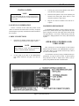
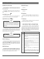
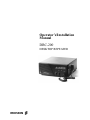
Operator’s/Installation
Manual
DRC-200
DESKTOP REPEATER
ERICSSONZ
AE/LZT 123 1899 R1B
REVISION HISTORY
REVISION
DATE
REASON FOR CHANGE
R1A
June - 96
Original
R1B
Sept - 96
Correct Figure 1 and update DCG codes. Minor corrections to text.
NOTICE!
This manual covers Ericsson and General Electric products manufactured and sold by Ericsson Inc.
NOTICE!
Repairs to this equipment should be made only by an authorized service technician or facility designated by the supplier. Any
repairs, alterations or substitution of recommended parts made by the user to this equipment not approved by the manufacturer
could void the user’s authority to operate the equipment in addition to the manufacturer’s warranty.
NOTICE!
The software contained in this device is copyrighted. Unpublished rights are reserved under the copyright laws of the
United States.
This manual is published by Ericsson Inc., without any warranty. Improvements and changes to this manual necessitated by
typographical errors, inaccuracies of current information, or improvements to programs and/or equipment, may be made by
Ericsson Inc., at any time and without notice. Such changes will be incorporated into new editions of this manual. No part of
this manual may be reproduced or transmitted in any form or by any means, electronic or mechanical, including photocopying
and recording, for any purpose, without the express written permission of Ericsson Inc.
Copyright© June 1996, Ericsson Inc.
2
AE/LZT 123 1899 R1B
TABLE OF CONTENTS
Page
DESCRIPTION . . . . . . . . . . . . . . . . . . . . . . . . . . . . . . . . . . . . . . . . . . . . . . . . .
4
INSTALLATION . . . . . . . . . . . . . . . . . . . . . . . . . . . . . . . . . . . . . . . . . . . . . . . .
5
LOCATION CONSIDERATION . . . . . . . . . . . . . . . . . . . . . . . . . . . . . . . . . . . . .
5
CABLE CONNECTIONS . . . . . . . . . . . . . . . . . . . . . . . . . . . . . . . . . . . . . . . . .
5
HANDHELD MICROPHONE . . . . . . . . . . . . . . . . . . . . . . . . . . . . . . . . . . . . . .
5
OPERATING CONTROLS AND INDICATORS . . . . . . . . . . . . . . . . . . . . . . . . . . . . . . .
5
POWER ON/OFF Switch . . . . . . . . . . . . . . . . . . . . . . . . . . . . . . . . . . . . . . . . .
6
VOLUME Control . . . . . . . . . . . . . . . . . . . . . . . . . . . . . . . . . . . . . . . . . . . . .
6
SQUELCH Control . . . . . . . . . . . . . . . . . . . . . . . . . . . . . . . . . . . . . . . . . . . .
6
MONITOR Button . . . . . . . . . . . . . . . . . . . . . . . . . . . . . . . . . . . . . . . . . . . . .
6
REPEAT Button . . . . . . . . . . . . . . . . . . . . . . . . . . . . . . . . . . . . . . . . . . . . . .
6
BZ Indicator . . . . . . . . . . . . . . . . . . . . . . . . . . . . . . . . . . . . . . . . . . . . . . . .
6
TX Indicator . . . . . . . . . . . . . . . . . . . . . . . . . . . . . . . . . . . . . . . . . . . . . . . .
6
MULTIFUNCTION CONNECTOR . . . . . . . . . . . . . . . . . . . . . . . . . . . . . . . . . . . . . .
6
MULTIPLE CG/DCG DECODE . . . . . . . . . . . . . . . . . . . . . . . . . . . . . . . . . . . . . . . .
7
OPERATION . . . . . . . . . . . . . . . . . . . . . . . . . . . . . . . . . . . . . . . . . . . . . . . . . .
7
INITIAL . . . . . . . . . . . . . . . . . . . . . . . . . . . . . . . . . . . . . . . . . . . . . . . . . .
7
GENERAL . . . . . . . . . . . . . . . . . . . . . . . . . . . . . . . . . . . . . . . . . . . . . . . . .
7
PTT OPERATION . . . . . . . . . . . . . . . . . . . . . . . . . . . . . . . . . . . . . . . . . . . . .
7
MAINTENANCE . . . . . . . . . . . . . . . . . . . . . . . . . . . . . . . . . . . . . . . . . . . . . . . .
8
SIMPLIFIED TROUBLESHOOTING . . . . . . . . . . . . . . . . . . . . . . . . . . . . . . . . . . . . .
8
SUMMARY OF DEALER’S PROGRAMMING OPTIONS . . . . . . . . . . . . . . . . . . . . . . . . .
8
Channel Guard Tones (CTCSS) . . . . . . . . . . . . . . . . . . . . . . . . . . . . . . . . . . . . . .
9
Digital Channel Guard Codes . . . . . . . . . . . . . . . . . . . . . . . . . . . . . . . . . . . . . . .
10
ACCESSORIES . . . . . . . . . . . . . . . . . . . . . . . . . . . . . . . . . . . . . . . . . . . . . . . . .
10
LIMITED WARRANTY . . . . . . . . . . . . . . . . . . . . . . . . . . . . . . . . . . . . . . . . . . . .
12
FIGURES
Figure 1 - Front Panel Details . . . . . . . . . . . . . . . . . . . . . . . . . . . . . . . . . . . . . . . . . .
4
Figure 2 - Rear Panel Details . . . . . . . . . . . . . . . . . . . . . . . . . . . . . . . . . . . . . . . . . .
5
Figure 3 - DB15 Connector Pin Positions - Rear Panel View . . . . . . . . . . . . . . . . . . . . . . . . . .
7
3
AE/LZT 123 1899 R1B
DESCRIPTION
NOTE
The DRC-200 is a state-of-the-art Desktop Repeater for
operation in the Land Mobile UHF (450-470 MHz) frequency band.
The repeater operates in the UHF band with a 25 watt
(without duplexer connected) RF output. Low power operation of 2 Watts is also available (Dealer programmable). The
built-in switching power supply automatically configures itself for operation on 120 VAC or 240 VAC, 50/60 Hz.
The unit features built-in Digital Channel Guard (DCG)
and standard Channel Guard (CG) tone squelch. In addition,
an external encoder and decoder can be utilized. A programmable CW Identifier is also included.
The radio has been programmed by the dealer. A list of
items determining the radio’s configuration should be available from the dealer. See page 8 for a list of Dealer Programming Options and page 13 for a blank form for
recording the Unit’s configuration. The radio’s program is
stored in non-volatile memory, which does not require a battery back-up.
In this manual, the words repeater, radio and unit are
used interchangeably.
See Figure 1 below for Repeater Front Panel details.
The Unit comes with the following standard accessories:
• Duplexer, installed
• Microphone Hang-up Clip with mounting hardware
• Operator’s/Installation Manual AE/LZT 123 1899
• Duplexer Tuning Manual AE/LZB 119 1910
Optional accessories include:
• Handheld Microphone with Coiled Cable
• Heavy Duty Desk Microphone
Figure 1 - Front Panel Details
4
AE/LZT 123 1899 R1B
INSTALLATION
NOTE
3.
If used, plug in the External Speaker. This disconnects the Unit’s internal speaker.
4.
Install the microphone’s cable in the modular jack
located on the front panel. There will be a click
when the connector is fully seated.
5.
Plug the AC cord into a suitable 120 or 240 AC receptacle.
It is recommended that the repeater and antenna installations be performed by a technician qualified in
2-way radio.
LOCATION CONSIDERATION
HANDHELD MICROPHONE
Choose a location for the radio that permits several
inches of clearance all around. This is necessary for proper
heat dissipation, especially around the heat sink mounted on
the rear panel.
CABLE CONNECTIONS
1.
Install the TX and RX antenna cables on their respective N type connectors. See Figure 2 below.
If a handheld microphone is used, a hang-up clip (supplied) can be mounted on the Unit’s right side near the front
panel. Using the one screw at the upper front corner and the
one approximately 2 1/2" below it, install the clip so that the
microphone’s hang-up button can be easily slid downward
in place.
OPERATING CONTROLS AND
INDICATORS
NOTE
When duplexer is used, antenna connection is
made to connector labeled ANTENNA.
2.
If used, plug in the cable to the Multifunction
Port’s DB15 connector. See page 6 for more details.
This section gives a brief description of each control,
button and status indicator. The OPERATION section provides more details on each of these and how they relate to
the unit’s overall operation.
As each button is pressed, a beep (if enabled; dealer programmable; see Page 8) will be heard. A high frequency
beep indicates the ON or enabled state, while a low frequency beep indicates the OFF or disabled state.
Figure 2 - Rear Panel Details.
5
AE/LZT 123 1899 R1B
POWER ON/OFF Switch
Power ON/OFF is a rocker switch. Press in at the top
end to turn the unit ON. Press in at the bottom end of it to
turn the radio OFF.
The indicator (LED) at the left end of the window (labeled POWER) should be lighted green when the unit is
ON.
REMOTE Button
Not used.
REM Indicator
Not used.
BZ Indicator
VOLUME Control
Use this knob to vary the receiver’s audio output level.
This also varies the audio level to an external speaker.
This green LED labeled BZ will be lighted whenever a
signal is received. In other words, the channel is busy (in
use).
SQUELCH Control
TX Indicator
NOTE
Do not turn the knob to maximum clockwise position. Turning the SQUELCH control significantly
past (clockwise) the threshold of quieting may adversely reduce receiver sensitivity and communications range.
Use this knob to eliminate speaker noise when not receiving a transmission. For proper operation, turn the knob
counter-clockwise until noise is heard. Then turn the knob
clockwise until the noise just disappears.
When the repeater’s transmitter section is activated, the
red indicator labeled TX will be lighted.
MULTIFUNCTION CONNECTOR
The female DB15 connector, labeled MULTIFUNCTION PORT and located on the rear panel, provides for interfacing to a remote control device (DC, Tone or Local), an
Interconnect Control panel or for RS232 data input. See
Figure 3 for pin configuration. The purpose and/or specification of each pin is as follows:
Pin No.
NOTE
When adjusting the squelch control, the Radio
should be in the MONITOR Mode.
1
Ground
2
Remote PTT; a low (ground) will cause the Unit to
transmit with User No. 1’s tone and the Remote TX
Audio (Pin 7).
3
Remote RX Audio Output; buffered de-emphasized
receiver audio.
4
Data PTT; a low (ground) will cause the Unit to
transmit with Data In audio (Pin 11).
5
Interconnect PTT; a low (ground) will cause the Unit to
transmit with User #16 tone and the Interconnect TX
Audio (Pin 14).
6
Switched +13.8 VDC; provides a low current (less than
1 A) voltage source.
7
Remote TX Audio Input; is pre-emphasized by the
Unit.
8
Carrier Operated Signal (COS); output will be low
(transistor turned on) when the Repeater’s squelch
opens (breaks), regardless if Repeater’s audio is muted
or not.
MONITOR Button
Pressing this button toggles the unit into and out of the
Monitor Mode. When the unit is in the Monitor Mode, the
yellow LED labeled MON will be lighted. Also, any input
signal to the unit’s receiver can be heard, even if it has tone
coding such as CG or DCG.
REPEAT Button
Pressing this button toggles the unit into and out the Repeater Mode. The yellow LED labeled REP is lighted when
the Repeater Mode is enabled. The unit will NOT transmit
as a repeater unless the Repeater Mode is enabled.
Purpose/Specification
Continued
6
AE/LZT 123 1899 R1B
Continued
erated as No. 18, it then cannot also be re-generated as No.
23 .
Pin No.
Purpose/Specification
9
Discriminator’s Audio Output; buffered unprocessed
(not de-emphasized) audio.
10
Interconnect RX Audio
emphasized receiver audio.
Output;
buffered
de-
11
Data In; 4800 BAUD (2400 Hz) Maximum.
12
Remote Audio B. Not Applicable
13
External
CG/DCG
Input;
modulates
the
VCO/Reference Oscillator; External Encoding must be
selected for the Encode Tone.
14
Interconnect TX Audio Input; is pre-emphasized by the
Unit.
15
Interconnect Control Output; goes Low when User #16
tone is decoded (or if the External Decode pin is low).
One of the 16 different tones or codes can be an input
from an external encoder. The external encoder signal has
priority over the Unit’s built-in encoder.
OPERATION
INITIAL
Turn on the unit. If squelch hasn’t been set yet, put the
unit into the Monitor Mode. If the yellow MON LED is not
lighted, press the MONITOR button. Set the Volume Control approximately to its 9 o’clock position. Then turn the
Squelch Control counter-clockwise until "noise" is heard.
At this time, the Volume Control can now be set for the
desired audio listening level. It can also be set later, when an
actual signal is being received. The Volume Control has no
effect on the transmitter audio.
Figure 3 - DB15 Connector Pin Positions
- Rear Panel View.
MULTIPLE CG/DCG DECODE
The unit’s built-in decoder can be programmed to accept
up to 16 different user’s CG tones or DCG codes and properly decode each one. There can be any combination of
tones or codes as long as the total is not more than 16. User
No. 16’s tone or code is always associated with Interconnect
Control.
The tone or code that is actually transmitted is not the
original one received, but one that is re-generated by the
unit. The generated tone or code can be a different tone or
code, as determined by the unit’s configuration programmed
by the dealer. For example, if the CG tone received is No.
12 (100.0 Hz), the Unit can be programmed to transmit No.
18 (123.0 Hz) or even a DCG code. However, a received
tone (or code) cannot be re-generated for more than one
tone (or code), whether it is the same or different tone
(code). For example, if received tone No. 12 is to be re-gen-
Now turn the Squelch knob clockwise slightly past the
point where the noise just disappears. This is the proper position for all normal squelched operations. If "noise" is occasionally heard, turn the Squelch Control slightly more
clockwise. If desired, the unit can now be taken out of the
Monitor Mode by pressing the MONITOR button. The
MON indicator should turn off.
GENERAL
If the unit is to be used as a self-controlling (receiver operation) repeater, press the REPEAT button to light the REP
LED.
PTT OPERATION
The operation of the radio’s PTT function has 5 priority
levels (1 being the highest) as follows:
1.
Local (front panel jack) microphone.
2.
Remote, if enabled (REM LED on).
3.
DATA (via DB15 connector).
4.
Interconnect Control panel.
5.
Receiver, if REPEAT Mode enabled (REP LED
on).
7
AE/LZT 123 1899 R1B
Although no repeater set-up would likely be configured
to accept all 5 PTTs, it is quite possible that at least two of
the five would be utilized. For example, the receiver’s PTT
action and the front panel’s PTT would probably be used
during the repeater’s initial installation and its checkout.
What the effect of prioritizing the various PTTs means is
that the TX audio of the PTT with the higher priority will
always be transmitted. For example, if the unit is receiving a
mobile unit, the audio being transmitted (repeated) is from
the receiver. Then if a remote control PTT is activated, the
audio from the remote is now transmitted (repeated).
NOTE
For In-Warranty service information, refer to the
Limited Warranty And Repair Information paragraph.
For future reference, please record:
Product Code ________________________________
FCC Identifier________________________________
MAINTENANCE
Serial No.____________________________________
NOTE
Date Purchased________________________________
All adjustments affecting transmitter power output,
carrier frequency or modulation MUST be performed by a qualified electronics technician.
Dealer_______________________________________
CAUTION
SUMMARY OF DEALER’S
PROGRAMMING OPTIONS
Do NOT tamper with internal adjustments. Damage to
the equipment and/or improper operation may result.
1.
Service Reminder
Have the Repeater checked periodically by a qualified
electronics technician. A Maintenance Manual, AE/LZB
119 1882, is available.
It should be noted that if no user tones (or codes)
are selected, the unit will respond to any carrier received. In other words, if the unit is in the Repeater
Mode it will repeat any carrier received, regardless
if the carrier is tone (or code) encoded or not.
SIMPLIFIED TROUBLESHOOTING
Perform the simple checks indicated below prior to returning the Unit for service.
Trouble
Check antenna connections.
No sound.
AC power cord.
Volume control setting.
Check External speaker connection.
Doesn’t repeat mobile’s Is REP indicator lighted?.
transmission.
If not, press REPEAT button.
8
2.
Channel Guard Tones – any one of 50 CG Tones
can be programmed for any user. The Tone used for
a User’s decode (receive) tone can either be the
same, or different, from the user’s encode (transmit) tone. The same decode tone can not be used
for more than one user. However, the same encode
tone could be used for all 16 users if desired.
3.
Digital Channel Guard Codes – any one of 104
DCG Codes can be programmed for any user. The
Code used for a user’s decode (receive) code can
either be the same, or different, from the user’s encode (transmit) code. The same decode code can
Check
No reception.
Users – 1 to 16 users can be uniquely defined by:
their decode/encode tone or code; whether or not
there will be a courtesy beep; whether or not there
will be an encoding tone or code transmitted during Hang Time. User No. 1 is frequently referred to
as the "Boss tone". User No. 16 is reserved for Interconnect Control applications. A user may consist of one or many subscribers (or mobile units)
assigned to the same tone or code.
AE/LZT 123 1899 R1B
not be used for more than one user. However, the
same encode code could be used for all 16 users if
desired.
4.
5.
6.
7.
External Encoder/Decoder – any one of the 16 user
tones or codes can be programmed for using an external encoder.
Courtesy Beep – each user can be programmed to
provide a beep for 100 milliseconds after the originating transmission is stopped. This signals the receiving unit(s) that the originating unit has quit
transmitting.
Button Beep – the unit can be programmed to
either beep or not beep whenever one of the buttons (REPEAT, MONITOR) is pressed. A high frequency beep indicates the button’s associated
function is enabled. A low frequency beep indicates the function is disabled. Error beeps are not
affected by this Option’s selection.
Low RF Power – the unit can be set to High (Normal) RF Power Out or Low RF Power Out. Low
Power Out can be manually adjusted to approximately 2 Watts.
Channel Guard Tones (CTCSS)
8.
Time-Out Timer – the unit’s Time-Out (carrier control) Timer can either be disabled or set to allow a
transmission of 15, 30 or 60 seconds or 2, 4, 8 or
16 minutes duration.
9.
Hang Time – the unit’s Hang Time (drop-out delay) can be disabled (0 seconds) or set from 1 to 15
seconds, in 1 second increments. Hang Time is the
duration of time starting either with the release of
any PTT Switch or when the unit’s received carrier
drops while in the Repeater Mode.
10. Encoded Hang Time – the unit’s transmission during Hang Time can be either encoded or not, depending upon the user’s configuration.
11. CW Ident – the unit can be programmed to transmit a Continuous Wave (CW) Morse Code Identification (Ident) consisting of 1 to 8 characters
comprised of any of the 26 letters (standard English alphabet) and any number 0 through 9.
12. CW Ident Interval – the unit can be programmed to
send its CW Ident upon activation of any PTT (except DATA PTT) after every 15, 30, 60 or 90 minutes of activity. The unit will also automatically
send its CW Ident upon the first PTT (except
DATA PTT) after power up and after every 10 minutes of inactivity.
50 Tones
CTCSS tones are specified by a code number in the PC programmer. The following is the relationship between the code
number and the resulting CTCSS tone frequency in Hz.
Code
000 = No Tone = Carrier Squelch
001 = 67.0
011 = 97.4
021 = 136.5
031 = 192.8
041 = 165.5
002 = 71.9
012 = 100.0
022 = 141.3
032 = 203.5
042 = 171.3
003 = 74.4
013 = 103.5
023 = 146.2
033 = 210.7
043 = 177.3
004 = 77.0
014 = 107.2
024 = 151.4
034 = 218.1
044 = 183.5
005 = 79.7
015 = 110.9
025 = 156.7
035 = 225.7
045 = 189.9
006 = 82.5
016 = 114.8
026 = 162.2
036 = 233.6
046 = 196.6
007 = 85.4
017 = 118.8
027 = 167.9
037 = 241.8
047 = 199.5
008 = 88.5
018 = 123.0
028 = 173.8
038 = 250.3
048 = 206.5
009 = 91.5
019 = 127.3
029 = 179.9
039 = 69.4
049 = 229.1
010 = 94.8
020 = 131.8
030 = 186.2
040 = 159.8
050 = 254.1
9
AE/LZT 123 1899 R1B
Digital Channel Guard Codes
104 codes
CDCSS codes are specified by a code number in the PC programmer. The following is the relationship between the PC
programming code number and the resulting TIA/EIA CDCSS code and its inverted equivalent.
Code
DCS
Inv.
DCS
Code
DCS
Inv.
DCS
Code
DCS
Inv.
DCS
Code
DCS
Inv.
DCS
Code
DCS
Inv.
DCS
051
023
047
072
131
364
093
251
165
114
371
734
135
532
343
052
025
244
073
132
546
094
252
462
115
411
226
136
546
132
053
026
464
074
134
223
095
255
446
116
412
143
137
565
703
054
031
627
075
143
412
096
261
732
117
413
054
138
606
631
055
032
051
076
145
274
097
263
205
118
423
315
139
612
346
056
036
172
077
152
115
098
265
156
119
431
723
140
624
632
057
043
445
078
155
731
099
266
454
120
432
516
141
627
031
058
047
023
079
156
265
100
271
065
121
445
043
142
631
606
059
051
032
080
162
503
101
274
145
122
446
255
143
632
624
060
053
452
081
165
251
102
306
071
123
452
053
144
654
743
061
054
413
082
172
036
103
311
664
124
454
266
145
662
466
062
065
271
083
174
074
104
315
423
125
455
332
146
664
311
063
071
306
084
205
263
105
325
526
126
462
252
147
703
565
064
072
245
085
212
356
106
331
465
127
464
026
148
712
114
065
073
506
086
223
134
107
332
455
128
465
331
149
723
431
066
074
174
087
225
122
108
343
532
129
466
662
150
731
155
067
114
712
088
226
411
109
346
612
130
503
162
151
732
261
068
115
152
089
243
351
110
351
243
131
506
073
152
734
371
069
116
754
090
244
025
111
356
212
132
516
432
153
743
654
070
122
225
091
245
072
112
364
131
133
523
246
154
754
116
071
125
365
092
246
523
113
365
125
134
526
325
ACCESSORIES
The following accessories are available:
10
KRD 103 121/11
PC Programming Kit (consists of the following)
KRD 103 121/12
Programming Software
KRD 103 121/13
Instruction Sheet
KRD 103 121/14
Interface Adapter
KRD 103 121/15
Programming Cable
KRD 103 121/31
Handheld Microphone
AE/LZT 123 1899 R1B
You may use this form to record the Unit’s configuration.
User
Memo
Decode
Tone (Hz)
or Code
Encode
Tone (Hz)
or Code
Encode
During
Hang Time
Courtesy
Beep
Y/N
Y/N
Notes/Comments
1
2
3
4
5
6
7
8
9
10
11
12
13
14
15
16
Receive Frequency:
MHz
Transmit Frequency:
MHz
RF Output Power:
(High/Low
or record Watts)
Beep on Button Press:
(Yes/No)
Time-Out Timer:
❑ Seconds❑ Minutes
Hang Time:
Seconds
CW Ident Interval:
Minutes
CW Ident:
(up to 8 characters)
NOTE: This page only may be copied without violating copyright.
11
AE/LZT 123 1899 R1B
LIMITED WARRANTY
A.
Ericsson Inc. (hereinafter “Seller”) warrants to the original purchaser for use
(hereinafter “Buyer”) that the Equipment manufactured by Seller shall be free
from defects in material, workmanship and title and shall conform to its published
specifications. With respect to any Equipment not manufactured by Seller (except
for integral parts of Seller’s Equipment to which warranties set forth above shall
apply), Seller gives no warranty and only the warranty, if any, given by the manufacturer shall apply. Batteries are excluded from this warranty but are warranted
under a separate Nickel-Cadmium Battery Warranty.
B.
Seller’s obligations set forth in Paragraph C below shall apply only to failures to
meet the above warranties (except as to title) occurring within the following periods of time from the date of sale to the Buyer and are conditioned on Buyer’s giving written notice to Seller within thirty (30) days of such occurrence:
1. for fuses, incandescent lamps, vacuum tubes and non-rechargeable batteries,
operable on arrival only.
2. for parts and accessories (except as noted in B.1) sold by Seller’s Service
Parts Operation, ninety (90) days.
3. for all other Equipment of Seller’s manufacture, one (1) year.
C.
If any Equipment fails to meet the foregoing warranties, Seller shall correct the
failure by repairing Buyer’s Equipment or providing Buyer, at Seller’s option, with
either a new or reconditioned unit of Equipment. Any repaired or replacement
unit furnished by Seller hereunder shall be warranted for the remainder of the
warranty period of the original Equipment purchased by Buyer.
D.
Seller’s obligations under Paragraph C shall not apply to any Equipment, or part
thereof, which: (i) has been modified or otherwise altered other than pursuant to
Seller’s written instructions or written approval; or (ii) is not properly stored, installed, used, maintained or repaired; or (iii) has been subjected to any other kind
of misuse or detrimental exposure or has been involved in an accident; or (iv) is
incorporated into another product; or (v) is purchased or serviced outside the
United States.
E.
The preceding paragraphs set forth the exclusive remedies for claims (except as
to title) based upon defects in the Equipment, whether the claim is in contract,
warranty, tort (including negligence), strict liability or otherwise, and however instituted. Upon the expiration of the warranty period, all such liability shall terminate.
The foregoing warranties are exclusive and in lieu of all other warranties, whether
oral, written, expressed, implied or statutory. NO IMPLIED OR STATUTORY
WARRANTIES OF MERCHANTABILITY OR FITNESS FOR PARTICULAR PURPOSE SHALL APPLY. IN NO EVENT SHALL THE SELLER BE LIABLE FOR
ANY INCIDENTAL, CONSEQUENTIAL, SPECIAL, INDIRECT OR EXEMPLARY
DAMAGES.
F.
This warranty applies only within the United States.
ECR-5473
Ericsson Inc.
Private Radio Systems
Mountain View Road
Lynchburg, Virginia 24502
1-800-528-7711 (Outside USA, 804-528-7711)
AE/LZT 123 1899 R1B
Printed in U.S.A.