1
Handbook for Siemens Integral Monitoring Unit
667/HB/22380/002
SIEMENS PLC,
Sopers Lane,
POOLE, Dorset
BH17 7ER
SYSTEM/PROJECT/PRODUCT: Siemens IMU
HANDBOOK FOR THE
SIEMENS T400, ST700 AND ST800
INTEGRAL MONITORING UNIT
PREPARED: Paul Cox
FUNCTION: Software Engineer
This Document is Electronically Held and Approved in Meridian
A ‘Paper Insert’ Appendix is held in the Registry – See Page 2
ISSUE:
01.00A
01.00B
01.00C
01.00D
01.00
02.00A
02.00B
02.00
03.00
04.00
05.00
CHANGE REF.:
ANL00311
ANL00760
TS000545
TS002377
DATE:
06/10/93
29/03/94
26/04/94
23/09/94
24/04/95
11/04/96
15/08/96
10/12/96
22/08/97
18/09/01
09/12/04
This is an unpublished work the copyright in which vests in Siemens PLC. All rights
reserved.
The information contained herein is the property of Siemens PLC and is supplied
without liability for errors or omissions. No part may be reproduced or used, except as
authorised by contract or other written permission. The copyright and the foregoing
restriction on reproduction and use extend to all media in which this information may be
embodied.
Issue 05.00 – Page 1
Handbook for Siemens Integral Monitoring Unit
667/HB/22380/002
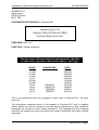
ISSUE STATE
Note: Source of documents is shown under Type as below.
1=Paper, 2=VAX, 3=Microfilm, 4=Caltext Disc, 5=DECmate Disc, 6=Paper
Insert, 7=MAC Disc, 8=Lifespan, 9=SUN, 10=Other, 11=Meridian
The document comprises the following components:
Pages
Current Issue
Type
Part ID
1 to 47
1 to 6
05.00
1
11
6*
667/HB/22380/002
667/HB/22380/002
* TCSU Technical Instruction No. 26
Issue 05.00 – Page 2
Handbook for Siemens Integral Monitoring Unit
667/HB/22380/002
SAFETY WARNING
In the interests of Health and Safety, when using or servicing this equipment, the
following instructions must be noted and adhered to:
i) Only skilled or instructed personnel with relevant technical knowledge and
experience, who are also familiar with the safety procedures required when
dealing with modern electrical / electronic equipment are to be allowed to use
and / or work on the equipment. All work shall be performed in accordance with
the Electricity at Work Regulations 1989.
ii) Such personnel must take heed of all relevant notes, cautions and warnings in
this handbook and any other document or handbook associated with the Traffic
Controller.
a) The equipment must be correctly connected to the specified incoming
power supply.
b) The equipment must be disconnected / isolated from any incoming power
supply before removing any protective covers, or working on any part from
which protective covers have been removed.
c) The Integral Facilities PCB contains a Lithium Battery that should be
disposed of in a safe manner. For further details, refer to Siemens Code
of Practice CP526.
TELECOMMUNICATIONS APPROVAL WARNING
The Siemens Integral Monitoring Unit connects to the PSTN using an external modem
that is Approved for connection to British Telecommunications PSTN lines as defined in
BS6305.
The Integral Monitoring Unit is covered by the General Approval for indirect connection
of apparatus under Section 22 of the 1984 Telecommunications Act, Approval Number
NS/G/1234/J/100003. The mark of approval for the external modem must not be
applied to the Integral Monitoring Unit / Traffic Controller as a whole.
Issue 05.00 – Page 3
Handbook for Siemens Integral Monitoring Unit
667/HB/22380/002
CONTENTS
1.
INTRODUCTION..................................................................................................... 7
1.1
Purpose ............................................................................................................ 7
1.2
Scope ............................................................................................................... 7
1.3
Related Documents .......................................................................................... 7
1.4
Definitions......................................................................................................... 8
1.5
Issue History..................................................................................................... 8
2.
GENERAL DESCRIPTION...................................................................................... 9
2.1
Overview........................................................................................................... 9
2.2
UTC Controllers And ‘TC8 Mode’ ..................................................................... 9
2.3
Modem.............................................................................................................. 9
2.4
Lamp Monitoring............................................................................................... 9
2.5
Last Gasp Dial .................................................................................................. 9
2.6
General Purpose Inputs / Outputs .................................................................. 10
2.7
Handset Access.............................................................................................. 10
2.8
Interfaces........................................................................................................ 10
2.9
Power Supply ................................................................................................. 10
2.10 Size................................................................................................................. 10
3.
INSTALLING THE IMU RETRO-FIT KIT............................................................... 11
3.1
General........................................................................................................... 11
3.2
Check Controller Processor PCB ................................................................... 11
3.2.1 T400 Controllers ......................................................................................... 11
3.2.2 ST700 and ST800 Controllers..................................................................... 12
3.3
Configuring The Integral Facilities PCB .......................................................... 13
3.3.1 Configuring the Switches and Links on the PCB......................................... 14
3.4
Installing The Integral Facilities PCB .............................................................. 16
3.5
Installing The Modem (Not UTC Controllers).................................................. 16
3.6
Installing The Battery (Not UTC Controllers) .................................................. 16
3.7
Connecting The IMU....................................................................................... 17
3.7.1 Extended System Bus................................................................................. 19
3.7.2 Power and Local I/O Cable ......................................................................... 19
3.7.3 RS232 Cable (Not UTC Controllers) ........................................................... 20
3.7.4 Modem Telephone Connection (Not UTC Controllers)................................ 22
3.7.5 Modem Power Connection (Not UTC Controllers) ...................................... 22
3.7.6 Battery Connections (Not UTC Controllers) ................................................ 22
3.7.7 Lamp Monitoring Inputs (T400 Only)........................................................... 23
4.
COMMISSIONING ................................................................................................ 26
4.1
General........................................................................................................... 26
4.2
Initialisation..................................................................................................... 26
4.2.1 Power on the Controller .............................................................................. 26
4.2.2 Switch on the LGD Battery (Not UTC Controllers) ...................................... 26
4.2.3 Check the Power LED on the IMU is illuminated......................................... 26
4.2.4 Operate the RESET Switch on the IMU ...................................................... 26
4.3
Configure The IMU ......................................................................................... 27
4.3.1 Connect the Maintenance Terminal to the Controller Handset Port ............ 27
4.3.2 Enable TC8 Mode (At UTC Controllers)...................................................... 27
4.3.3 Initiate a Local Loopback Test of the Modem (Not UTC Controllers) .......... 28
Issue 05.00 – Page 4
Handbook for Siemens Integral Monitoring Unit
667/HB/22380/002
4.3.4 Switch to the Controller Handset Commands ............................................. 28
4.3.5 Perform Normal Controller Commissioning Sequence................................ 28
4.3.6 Check IMU Current Fault Log ..................................................................... 29
4.3.7 Load IMU Software (Not UTC Controllers).................................................. 29
4.3.8 Confirm IMU Operation (Not UTC Controllers)............................................ 29
4.4
Commission The IMU ..................................................................................... 29
4.4.1 Set Commissioning Flag on IMU (Not UTC Controllers) ............................. 29
4.4.2 Lamp Monitoring (T400 Only) ..................................................................... 29
4.4.3 Local IMU Digital Inputs / Outputs (Not UTC Controllers) ........................... 30
4.5
Clear IMU Fault Log........................................................................................ 30
4.5.1 Clear Commissioning Flag (Not UTC Controllers)....................................... 30
4.5.2 Check IMU Fault Log .................................................................................. 30
5.
MAINTENANCE .................................................................................................... 31
5.1
Status LED’s................................................................................................... 31
5.2
Effect Of Incorrect Switch / Link Settings........................................................ 32
5.3
Fault Finding After Installation ........................................................................ 32
Fuses.............................................................................................................. 33
5.4
5.5
Lithium Battery................................................................................................ 33
5.6
Nickel-Cadmium Battery ................................................................................. 33
6.
HANDSET COMMANDS....................................................................................... 34
6.1
Miscellaneous Maintenance Commands ........................................................ 34
6.2
TC8 Mode Handset Commands .....................................................................35
6.3
Input / Output Handset Commands ................................................................ 36
6.4
Lamp Supply Monitoring Commands.............................................................. 36
6.5
Lamp Monitoring Commands – Maintenance ................................................. 37
6.6
Lamp Monitoring Commands – Configuration ................................................ 38
6.7
Engineering Handset Commands ...................................................................38
6.8
Additional Information On Certain Handset Commands ................................. 39
6.8.1 Battery Test Time (BTT).............................................................................. 39
6.8.2 Green State Locations (LCP) ...................................................................... 40
6.8.3 Learn Status Bits (KAS and KLS) ............................................................... 41
6.8.4 Current Profile Store (LMR) ........................................................................ 42
6.8.5 Fault Log Commands (FLC and FLH) ......................................................... 43
6.9
Fault Display Codes and Text......................................................................... 45
Last Page of the Handbook ........................................................................................... 47
TCSU Technical Instruction No. 26 .......................................................................... 1 to 6
Table of Figures
Figure 1 – Layout of Switches and Links on Integral Facilities Processor ..................... 13
Figure 2 – 8V / 12V Links for Modem Supply ................................................................ 14
Figure 3 – Lithium Battery Switch Setting ...................................................................... 15
Figure 4 – Last Gasp Dial Battery Switch ...................................................................... 15
Figure 5 – Overview of Components ............................................................................. 17
Figure 6 – IMU Connector PL5 ...................................................................................... 19
Figure 7 – Short Length Serial Cable to GEMINI Bus Processor................................... 21
Issue 05.00 – Page 5
Handbook for Siemens Integral Monitoring Unit
667/HB/22380/002
Figure 8 – Status LED’s on the Integral Facilities Processor Card ................................ 31
Issue 05.00 – Page 6
Handbook for Siemens Integral Monitoring Unit
667/HB/22380/002
1. INTRODUCTION
1.1 PURPOSE
The purpose of this document is a guide to the Siemens Integral Monitoring Unit
for the T400, ST700 and ST800 Traffic Controllers. It is intended to provide
professional Installation and Maintenance personnel with information on how to
install, commission and maintain the Integral Monitoring Unit.
1.2 SCOPE
This document provides a general description of the Integral Monitoring Unit
fitted to various controller outercases, along with the details required for
Installation, Commissioning and Maintenance of the Unit.
1.3 RELATED DOCUMENTS
a) Engineering Specification for TCSU Integral Monitoring
Unit ................................................................................. 667/SA/20652/001
b) Full Functional Specification for the TCSU T400 Pelican
Integral Monitoring Unit ..................................................667/UH/25073/000
c) Full Functional Specification for the TCSU T400
Intersection Integral Monitoring Unit ...............................667/UH/25075/000
d) Full Functional Specification for Part Time Operation on
Individual Streams ..........................................................667/UH/25076/000
e) Full Functional Specification for ST700 / ST800
Controllers ......................................................................667/UH/25083/000
f) Circuit Diagram for T400 Integral Facilities Processor...667/DA/25169/ETC
g) T400 General Handbook ................................................667/HB/20200/000
h) T400 Installation & Commissioning Handbook ...............667/HE/20200/000
i) T400 Maintenance Handbook.........................................667/HA/20200/000
j) T400 Handset Handbook................................................667/HH/20200/000
k) ST800 General Handbook ..............................................667/HB/27000/000
l) ST800 Installation and Maintenance Handbook .............667/HE/27000/000
m) ST700 and ST800 Handset Handbook...........................667/HH/27000/000
n) ST700 Handbook............................................................667/HB/27880/000
o) GEMINI Traffic Outstation Handbook .............................667/HB/30600/000
Issue 05.00 – Page 7
Handbook for Siemens Integral Monitoring Unit
1.4 DEFINITIONS
DoT
IMU
LGD
LMU
MOVA
OMU
PSTN
PSU
STCL
ST700
ST800
T400
TCSU
TCUG
TfL
667/HB/22380/002
Department of Transport
Integral Monitoring Unit
Last Gasp Dial
Lamp Monitor Unit
Microprocessor Optimised Vehicle Actuation.
Outstation Monitor Unit
Public Switched Telephone Network
Power Supply Unit
Siemens Traffic Controls Ltd
Siemens Type 700 Pedestrian Controller
Siemens Type 800 Traffic Controller
STCL T400 Traffic / Pelican Controller
Traffic Control Systems Unit
Traffic Control User Group
Transport for London (the new name for TCSU-London)
1.5 ISSUE HISTORY
01.00A First Draft (Pelican IMU).
01.00B Review Draft.
01.00C Post review Draft.
01.00D Further Clarifications.
01.00
Incorporates comments from TCSU dated 6/2/95.
02.00A Document modified to include information on the intersection IMU
so that the document applies to both the T400 pelican and
intersection controllers.
02.00B Comments from STCL review included.
02.00
Incorporates changes requested by TCSU in FAX dated 21/11/96.
03.00
Incorporates changes for the Part Time on Individual Streams
Facility and the new fault codes FC59 and FC60 and use of the TfL
TCUG outercase.
04.00
Details of the ST700 and ST800 added.
05.00
Document modified to include information on configuring the IMU
for connecting to a GEMINI Bus Processor via the modem serial
link.
Issue 05.00 – Page 8
Handbook for Siemens Integral Monitoring Unit
667/HB/22380/002
2. GENERAL DESCRIPTION
2.1 OVERVIEW
The Integral Monitoring Unit is used with the Siemens T400, ST700 and ST800
Traffic Controllers to perform a multitude of different monitoring and control
functions such as lamp monitoring, monitoring the status of the controller for
faults, modifying values of timings in the controller etc.
The IMU consists of an Integral Facilities Processor PCB, a Modem, a
rechargeable Nickel-Cadmium Battery and a Mounting Panel. For a detailed
description of the Integral Monitoring Unit please refer to the Full Functional
Specification 667/UH/25073/000 (plus the various /UH/ supplements, see section
1.3) and the Engineering Specification for the TCSU Integral Monitoring Unit
667/SA/20652/001.
2.2 UTC CONTROLLERS AND ‘TC8 MODE’
For UTC sites where an OTU is connected to the telephone line rather than the
IMU, the IMU has a special ‘TC8 Mode’ (also see section 6.2 on page 35). In this
mode, it no longer uses its modem or its rechargeable battery (and both should
be disconnected from the IMU and removed from the controller outercase). If
required, two digital outputs from the IMU can be connected to the OTU to
provide two reply bits – ‘lamp fault’ and ‘any fault’ (see section 3.7.2 on page 19).
2.3 MODEM
An RS232 Serial Interface on the Integral Facilities Processor Card is used to
communicate with a modem external to the PCB itself. This allows the IMU to
use any modem suitable for the application.
2.4 LAMP MONITORING
On the T400, the IMU provides a Lamp Monitoring facility by means of 24
analogue inputs to the Integral Facilities Processor PCB. These allow for the
connection of up to 23 Current Monitoring Torroids and 1 Voltage Monitoring
Transformer.
On the ST700 and ST800, the controller provides the lamp monitoring with the
information passed from the controller to the IMU over the Extended System Bus
Interface. Therefore Current Monitoring Torroids and the Voltage Monitoring
Transformer are no longer connected to the Integral Facilities Processor PCB.
2.5 LAST GASP DIAL
A Last Gasp Dial facility is available using an external Nickel Cadmium battery to
provide power to the PCB. If there is a mains failure, this supports several dial
attempts to inform the instation of the mains power failure. The processor is able
to monitor the condition of the battery with a periodical test to ensure that it is
operating correctly.
Issue 05.00 – Page 9
Handbook for Siemens Integral Monitoring Unit
667/HB/22380/002
2.6 GENERAL PURPOSE INPUTS / OUTPUTS
The Integral Facilities Processor has four inputs and four outputs which is
additional to the normal I/O available on the controller. The inputs are standard
TR0141 type digital inputs and the outputs are voltage free relay contacts.
2.7 HANDSET ACCESS
Handset access to the Integral Monitoring Unit is carried out using an 80character terminal. This is connected to the handset port on the controller with
data passed to / from the Integral Monitoring Unit using the Extended System
Bus Interface.
2.8 INTERFACES
The Integral Facilities Processor PCB has five connectors to provide physical
connections to the following devices. Refer to Figure 1 on page 13 for the
position of the connectors on the PCB.
PL1
40-way IDC Header to Controller (Extended System Bus)
PL2
50-way IDC Header to Lamp Monitoring Sensors
PL3
25-way D Connector to Modem or GEMINI Bus Processor
PL4
16-way IDC Header (Proprietary Serial Link for Future Use)
PL5
34-way IDC Header to Power Supply and I/O Terminal block
2.9 POWER SUPPLY
The Integral Monitoring Unit requires the following power:
12V
@ 700mA (Max)
The 12V supply is regulated on board to provide
±5V required by the PCB circuitry (and some
modems). It is also regulated to provide 8V for
powering some modems.
24V
@ 80mA (Max)
The 24V supply is used for powering the digital input
circuits and for the Last Gasp battery charger.
The power requirements are supplied using the standard controller power
supplies, although the ST700 and ST800 are fitted with a DC/DC converter on
the modem-mounting panel to provide the 12V supply from the controller’s 24V
since the ST700/ST800 power supplies no longer provide 12V directly.
2.10 SIZE
The Integral Monitoring Unit is a Double Extended Euro Card size PCB
(233.4mm x 220mm). It fits in a standard T400 and ST800 Logic PCB rack and
has components no higher than 18mm from the surface of the PCB.
Issue 05.00 – Page 10
Handbook for Siemens Integral Monitoring Unit
667/HB/22380/002
3. INSTALLING THE IMU RETRO-FIT KIT
Note that the normal situation would be for the controller to be delivered with the
Integral Monitoring Unit already installed. However, in the event of failure in one
or more of the components of the IMU, it would be necessary to replace those
components. This section has therefore been written as though only the
Mounting Panel for holding the Modem (modem only fitted if required) and LGD
battery etc., and the LMU Current and Voltage Transformers are already fitted.
To replace or install any of the other components, follow the appropriate
instructions in this section.
3.1 GENERAL
Installation of the Integral Monitoring Unit is carried out in the following order:
• Section 3.2: Check controller processor PCB
• Section 3.3: Configure the IMU PCB via switches / links:
- Selection of the external modem supply (PL5 and PL9) where a modem
is fitted.
- Lithium Battery Switch (S2)
- Last Gasp Dial Battery Switch (S3)
• Section 3.4: Install the PCB into the Controller
• Section 3.5: Install the Modem. This step is required where a modem is to be
installed and not when the IMU is connected to a GEMINI Bus Processor via
a direct serial link.
• Section 3.6: Install the LGD Battery
• Section 3.7: Connect the necessary cabling
3.2 CHECK CONTROLLER PROCESSOR PCB
Operation of the IMU in a controller will not be possible until the correct
firmwares are fitted and the correct controller configuration is loaded.
3.2.1 T400 CONTROLLERS
The IMU requires a T400 Main Processor PCB that is at Issue 9 or greater. The
Issue of the PCB is marked on the bottom edge of the PCB viewed from above.
If the Issue of the Main Processor is 8 or less, then it must be replaced before
operation of the IMU can commence.
For the Pelican IMU firmware PB580, the T400 Controller must be fitted with
PB322 firmware issue 2 (or higher).
For the Pelican and Intersection IMU firmware PB581, the T400 Controller must
be fitted with PB322 issue 5 (or higher).
If the Part Time on Individual Streams Facility is required then the T400
Controller must be fitted with PB322 firmware issue 7 (or higher), and the IMU
must be fitted with PB581 firmware issue 2 (or higher).
Issue 05.00 – Page 11
Handbook for Siemens Integral Monitoring Unit
667/HB/22380/002
Important: The IMU firmware PB581 issue 2 should not be used with T400
firmware issue 6 (or earlier). Other issues of PB581 can be used with these
issues.
Pelican T400 Controllers must include Configuration and Conflict EPROM’s that
support the Integral Monitoring facility as listed below:
- DT064 and DT065 Single MCE1025 Pelican Controller (EM23208)
- DT066 and DT067 Dual MCE1025 Pelican Controller (EM23209)
- DT068 and DT069 Single MCE0145 Pedestrian Controller (EM23210)
NB: In each case, the first ‘DT’ number is the configuration EPROM and the
second ‘DT’ number is the conflict EPROM.
Intersection T400 Controllers must be configured using the Configurator IC3
issue 12 (or later) and the ‘Integral OMU’ facility must be enabled. The
Configurator IC3 Issue 14 (or higher) is required to configure the Part Time on
Individual Streams Facility.
3.2.2 ST700 AND ST800 CONTROLLERS
The controller must be fitted with the firmware PB800 issue 18 (or higher) and
the IMU must be fitted with PB581 issue 5 (or higher).
The ST700P Pedestrian and ST800 Intersection configurations require the
‘London IMU’ facility to be enabled and thus require IC4 version 6.2 (or later).
The TfL versions of the standard ST700P Pedestrian configurations are listed
below:
• E60710 – TfL ST700P Single or Dual Pelican
• E60711 – TfL ST700P Single or Dual Near-Side Pedestrian Crossing
• E60712 – TfL ST700P Single or Dual Pedestrian Blackout Crossing
Refer to the special instructions within these configurations for installation and
commissioning details for those ST700P pedestrian controllers.
Confirm that these are the correct configurations required for the site before
loading them into the ST700P.
Issue 05.00 – Page 12
Handbook for Siemens Integral Monitoring Unit
667/HB/22380/002
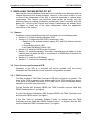
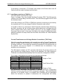
3.3 CONFIGURING THE INTEGRAL FACILITIES PCB
Figure 1 below shows the layout of the Integral Facilities PCB. The position of
the links, switches, fuses, connectors and status LED’s is shown.
PL4
(Future Use)
Active Fault LED
Comms Data LED
Call Status LED
12V Power Present LED
Unused LED
Watchdog Fail LED
PL1
Controller
Extended
System
Bus
Reset Switch
Off
On
PL3
Modem
RS232
Lithium Battery & Switch S2
1.6A QB
PL5
Power And
Local I/O
FS3
PL9 – Link for 8/12V Modem
500mA QB FS1 50mA QB
PL2
LMU
Inputs
FS2
LGD Battery Switch S3
Off
On
Unused PCB Area
Figure 1 – Layout of Switches and Links on Integral Facilities Processor
Ensure that the correct variant (667/1/25169/001) of the PCB has been supplied.
For details on the connections on PL5 see Figure 6 on page 19, and for details of
the connections on PL2 see section 3.7.7 (which starts on page 23). More
information on the status LED’s can be found in section 5.1 on page 31.
Safety Warning
The Integral Monitoring Unit PCB contains a Lithium Battery. Care must be taken
with the use and disposal of this battery. The handling precautions in Siemens
code of practice CP526 must be followed.
Issue 05.00 – Page 13
Handbook for Siemens Integral Monitoring Unit
667/HB/22380/002
3.3.1 CONFIGURING THE SWITCHES AND LINKS ON THE PCB
The voltage required by the modem is clearly labelled on the modem itself.
The IMU can supply any one of three different DC voltages 5V, 8V or 12V to the
modem from the connector PL5 on the front of the IMU (see Figure 6 on page
19).
To select 5V, fit the power cable to the modem to pin 22 of PL5.
To select 8V or 12V, fit the power cable to the modem to either pin 23 or 24 and
then select either 8V or 12V using PL9 below.
8V / 12V Modem Supply Link (PL9)
Link PL9 is a three-way link with two positions. These are used to select 8V or
12V operation for the external modem (see
Figure 2 below). The setting of this is dependent on the type of modem fitted with
the Integral Monitoring Unit.
12V
PL9
8V
Figure 2 – 8V / 12V Links for Modem Supply
Linking the centre pin on PL9 to the pin labelled 8V or the pin labelled 12V sets
the supply voltage to the external modem. This is done using the shorting link
supplied on the Integral Facilities PCB. This link is normally set in the 8V position
unless 12V operation is required.
Lithium Battery Switch (S2)
The Lithium Battery Switch S2 must be switched on to allow backup of the Data
RAM in the event of a power failure. Moving Switch S2 to the “ON” position (see
Figure 3 below) does this.
Issue 05.00 – Page 14
Handbook for Siemens Integral Monitoring Unit
667/HB/22380/002
Note: Due to the position of the switch on the PCB, it is very difficult to turn this
switch on after the board has been installed.
S2
OFF
Battery ON
Battery OFF
Figure 3 – Lithium Battery Switch Setting
Last Gasp Dial Battery Switch (S3)
The Last Gasp Dial Battery Switch (S3) should be set to the “OFF” position for
installation. It is located in the bottom left hand corner of the PCB with the “ON”
position marked in the silk-screen. This switch can be operated with the board in
position in the controller.
Battery
OFF
S3
ON
Battery
ON
Figure 4 – Last Gasp Dial Battery Switch
Issue 05.00 – Page 15
Handbook for Siemens Integral Monitoring Unit
667/HB/22380/002
3.4 INSTALLING THE INTEGRAL FACILITIES PCB
The Controller should be switched off before any insertion / removal of PCBs
takes place. It should only be switched on again after the insertion / removal is
complete and all connections have been made to any PCBs that have been
changed.
When all the necessary switches and links have been configured, the Integral
Facilities PCB should be installed as in
Figure 5 on page 17.
3.5 INSTALLING THE MODEM (NOT UTC CONTROLLERS)
The Modem used in the Integral Monitoring Unit is installed on the modem panel
mounted in the controller. The restraining bar should then be fastened down over
the modem to secure it firmly to the panel.
Where the modem has an On / Off Switch, this should be set to the ‘ON’ position
for normal operation. If it has a three position switch, i.e. ‘On/Auto/Off’, then the
switch should be set to the ‘auto’ position.
3.6 INSTALLING THE BATTERY (NOT UTC CONTROLLERS)
The Nickel-Cadmium Battery used with the Integral Monitoring Unit is also
mounted on the modem panel.
The battery clamp should be removed from the panel and the battery fitted to the
clamp with the battery leads freely available at the ends of the clamp. The clamp
should then be replaced on the modem panel and the nuts tightened to secure
the battery pack firmly to the modem panel.
Care should be taken when tightening the battery clamp to ensure that it is just
sufficient to prevent the battery from moving.
Issue 05.00 – Page 16
Handbook for Siemens Integral Monitoring Unit
667/HB/22380/002
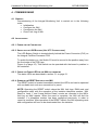
3.7 CONNECTING THE IMU
When the modem (as required), battery and Integral Facilities Processor have
been installed into the Controller the following connections must be made:
• Section 3.7.1: Extended System Bus Cable (PL1)
• Section 3.7.2: Power and Local I/O Cable (PL5)
• Section 3.7.3: RS232 Cable (PL3)
• Section 3.7.4 and 3.7.5: Modem Connections. This step is required where
a modem is installed and not when the IMU is connected to a GEMINI Bus
Processor via a direct serial link.
• Section 3.7.6: Battery Connections
• Section 3.7.7: LMU Inputs (PL2)
All the cable designators given in this section refer to the connections on the
Integral Facilities Processor PCB. Where appropriate, these are marked on the
cableforms used.
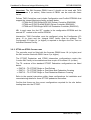
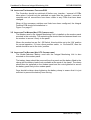
T400 SMALL OUTERCASE
T400 LARGE OUTERCASE
BT Socket
FRONT
IMU
CABLES
TO REAR
LGD Battery
Modem
Voltage
Transformer
IMU PCB
REAR
IMU PCB
Modem Mounting Panel
Figure 5 – Overview of Components
(See overleaf for the TfL TCUG Outercases)
Issue 05.00 – Page 17
Handbook for Siemens Integral Monitoring Unit
667/HB/22380/002
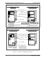
(THE LARGE AND SMALL TfL TCUG OUTERCASES ARE NOT SHOWN TO SCALE)
TfL TCUG SMALL OUTERCASE
T400 PELICAN
TfL TCUG LARGE OUTERCASE
T400 INTERSECTION
Modem Mounting Panel
LGD Battery
Modem
Voltage Transformer
PCBs
BT Socket
Current Transformers
Veh
Veh
Ped
Wait
Ped
Wait
Ped
R&G
Ped
R&G
First Pelican Stream
A
A
B
B
C
C
D
D
E
E
F
F
G
G
H
H
Second Pelican Stream
(Dual Pelicans Only)
?
I
I
J
J
K
K
L
L
M M
N
N
O
O
P
P
Additional sensor to monitor the
pedestrian wait indicators of phase ‘?’.
(THE LARGE AND SMALL TfL TCUG OUTERCASES ARE NOT SHOWN TO SCALE)
TfL TCUG SMALL OUTERCASE
ST700 PEDESTRIAN
TfL TCUG LARGE OUTERCASE
ST800 INTERSECTION
Modem Mounting Panel
ST700
LGD Battery
Modem
ST800
IMU PCB
BT Socket
Ped
R&G
Ped
Wait
First Pelican
Stream
Ped
R&G
Ped
Wait
Second Pelican
Stream (Dual
Pelicans Only)
Current Transformers for
ST700 Pedestrian Phases
(The Current Transformers for
other phases on the ST700
and all phases on the ST800
are built in to the Controllers)
Figure 5 – Overview of Components (Continued)
Issue 05.00 – Page 18
Handbook for Siemens Integral Monitoring Unit
667/HB/22380/002
3.7.1 EXTENDED SYSTEM BUS
The Extended System Bus is a ribbon cable that links all the logic PCBs of the
controller together. This should be plugged into PL1 (see
Figure 1 on page 13) and the latches closed.
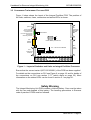
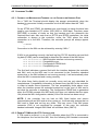
3.7.2 POWER AND LOCAL I/O CABLE
The Power and Local I/O Cable is connected to PL5 (see
Figure 1 on page 13) on the Integral Facilities PCB. The Berg Connector housing
should be plugged into PL5 and the latches closed to secure it into position.
1
12V 0V
0V
12V 0V
24V
IMU
Supply
(12V)
IMU
Supply
(24V)
fused
8V 0V
12V
8V 5V
12V
0V
–
0V
IN3 IN1 R4
R3
R2
R1
0V
+
0V
IN4 IN2 R4
R3
R2
R1
Battery
33
4 Digital
4 Digital
Inputs + Output Relays
2 Returns
Modem
Power
Figure 6 – IMU Connector PL5
See section 3.3.1 for details on the “Modem Power” connections.
See sections 2.9 and 5.4 for details on the “IMU Supply” connections.
The four general purpose inputs and four outputs for the IMU are then normally
available on the T400 controller I/O terminal blocks as detailed below. Note that
the same terminal block names and terminal numbers are used in the T400
Outercase and the TfL TCUG Outercase.
Input 1:
Input 2:
Input 3:
Input 4:
Output 1:
Output 2:
Output 3:
Output 4:
Single Pelican
TBD 13
TBD 14
TBD 15
TBD 16
TBD 17 & 18
TBD 19 & 20
TBD 21 & 22
TBD 23 & 24
Dual Pelican
Intersection
(TC8 Outputs*)
TBE 9
TBAA 1
–
TBE 10
TBAA 2
–
TBE 11
TBAA 3
–
TBE 12
TBAA 4
–
TBD 17 & 18 TBAA 5 & 6
–
TBD 19 & 20 TBAA 7 & 8
–
TBD 21 & 22 TBAA 9 & 10
‘Lamp Fault’
TBD 23 & 24 TBAA 11 & 12
‘Any Fault’
* See section 2.2 on page 9
The Work Specification for the controller should be checked. It may detail any
changes to this as well as identifying the terminal blocks used for the controller’s
I/O.
Issue 05.00 – Page 19
Handbook for Siemens Integral Monitoring Unit
667/HB/22380/002
3.7.3 RS232 CABLE (NOT UTC CONTROLLERS)
TO MODEM
The RS232 Cable to the modem is a single moulded cable (part number
667/7/25175/000).
The RS232 Cable connects the Integral Facilities Processor PCB to the modem.
It connects to PL3 (see Figure 1 on page 13) on the PCB and the 25-way D
Connection on the modem.
If the modem is provided with a 9-way D socket then it will have a 9-way to 25way Converter fitted such that the RS232 cable can be plugged into the 25-way
socket on the Converter.
The RS232 Cable should be connected to the Integral Facilities PCB and the
upper screwlock on the right angle connector tightened to the PCB connector.
The RS232 Cable should then be connected to the modem (or Converter) and
both screwlocks tightened to the modem connector (or Converter connector).
For routing of the RS232 and the Power and Local I/O Cables in the T400
cabinet, refer to
Figure 5 on page 17 and the notes below.
In a small T400 outercase (i.e. a Pelican T400), the cables are routed along the
side of the top PCB module to the back of the cabinet and the modem panel.
In a large T400 outercase (i.e. an Intersection T400), they are routed by the side
of the PCB modules to the panel at the rear.
In the T400 and ST800 Intersection Controller Large TfL TCUG Cabinets the
RS232 cable leaves the IFC and passes under the PCB rack before crossing the
controller and connecting to the modem. The Power and I/O Cable is passed
between the IFC and the PCB to its left, exiting the back of the PCB rack.
In the T400 Pelican Small TfL TCUG Cabinet the RS232 cable leaves the IFC
and is fed through a cut-out in the right hand side of the front panel before
crossing the controller to the modem. The Power and I/O Cable is passed
between the IFC and the PCB to its right, exiting at the back of the PCB rack.
In the ST700 Pelican Small TfL TCUG Cabinet the IFC cables run along the top
of the rack from the IFC card on the right to the modem mounting panel on the
left.
All cables should be secured into position using cable ties.
Issue 05.00 – Page 20
Handbook for Siemens Integral Monitoring Unit
667/HB/22380/002
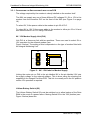
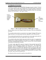
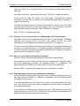
TO GEMINI BUS PROCESSOR
The RS232 connection to the GEMINI Bus Processor is a pair of cables. The first
is the single moulded cable (part number 667/7/25175/000) used for connection
to a modem. The second is a short length (15cm) ribbon cable with a 25-way Dtype connector and an 18-way IDC connector at opposite ends of the cable (part
number 667/1/26579/003) – see Figure 7 below.
D-type
connector
mated to
moulded
RS232
cable
IDC
connector
to GEMINI
Bus
Processor
Figure 7 – Short Length Serial Cable to GEMINI Bus Processor
The two cables connect the Integral Facilities Processor PCB to the GEMINI Bus
Processor.
The moulded cable should be connected to the Integral Facilities PCB and the
upper screwlock on the right angle connector tightened to the PCB connector.
The moulded cable should then be connected to the short length cable and both
screwlocks tightened to the short length cable D-type connector.
The combined cable should initially be routed inside the cabinet in a manner that
complies with a modem installation. Since there is no modem, the GEMINI Bus
Processor end of the cable should be routed to the rear of the 3U rack assembly
containing the GEMINI Bus Processor.
The short length cable IDC connector should be firmly inserted into the PL4
connector on the GEMINI Bus Processor PCB card. NOTE : The GEMINI Bus
Processor must be unpowered before this connection can be made. The
peripheral cards on the GEMINI Bus Processor must be removed to gain clear
access to the PL4 connector on the PCB card. Once the connection has been
made, the peripheral cards must be reattached to the GEMINI Bus Processor.
See GEMINI Traffic Outstation Handbook 667/HB/30600/000 for details of Bus
Processor card removal and replacement.
All cables should be secured into position using cable ties.
Issue 05.00 – Page 21
Handbook for Siemens Integral Monitoring Unit
667/HB/22380/002
3.7.4 MODEM TELEPHONE CONNECTION (NOT UTC CONTROLLERS)
The Telephone cable supplied with the modem should be connected from the
modem to the BT Socket in the controller outercase.
In controllers in TfL TCUG Outercases the BT Socket is in the BT Compartment
on the side of the controller.
In other outercases, the BT socket is mounted on the modem-mounting panel.
The Telephone cable is polarised to ensure the connection can only be made in
the correct manner. Any slack remaining in the telephone cable should be coiled
up and secured to the modem-mounting panel.
Where an existing installation is being modified so that the IMU is connected to a
GEMINI Bus Processor via a direct serial link, then the telephone cable is not
required. The telephone cable should either be removed from the cabinet or
disconnected from the modem. If the telephone cable is retained within the
cabinet, any slack should be coiled up and secured to the modem-mounting
panel.
3.7.5 MODEM POWER CONNECTION (NOT UTC CONTROLLERS)
The power connection to the modem is dependent on the type of modem that
has been supplied.
Care should be taken to ensure that the contacts of the plug do not short with the
modem mounting panel or the controller case. If the modem is removed in ‘TC-8
mode’ the power connector (if fitted) should be neatly insulated and tied back.
Note: Some modems have a small compartment to hold a 9v battery. This
should be checked, as this battery is not required and should be removed.
When connecting the modem power, it is advisable to have the modem
switch in the ‘off’ position to prevent accidental blowing of the modem
supply fuse, FS1 on the Integral Facilities Processor PCB.
The power connection is made using the jack plug connected to the Power and
Local I/O Cable from the Integral Facilities Processor PL5, see Figure 6 on page
19.
Where an existing installation is being modified so that the IMU is connected to a
GEMINI Bus Processor via a direct serial link, then the modem is not required.
The modem should either be removed from the cabinet or the modem power
connector be disconnected from the modem. In either case, the modem power
connector should be secured to the modem-mounting panel.
3.7.6 BATTERY CONNECTIONS (NOT UTC CONTROLLERS)
The battery connections are made using bullet crimps installed on the battery.
These are polarised and should be mated with the corresponding crimp on the
Power and Local I/O Cable connection on the modem panel.
Issue 05.00 – Page 22
Handbook for Siemens Integral Monitoring Unit
667/HB/22380/002
If the battery is removed in ‘TC-8 Mode’ the crimps on the Power and Local I/O
Cable should be neatly insulated and tied back.
3.7.7 LAMP MONITORING INPUTS (T400 ONLY)
The LMU Inputs connect to PL2 (see
Figure 1 on page 13) on the Integral Facilities Processor PCB. The LMU sensors
connect to a 54-way Berg Connector Shell. This should be plugged into PL2 and
the latches closed.
If the IMU is fitted to an ST700 or ST800 then the lamp monitoring is provided by
the controller so PL2 on the Integral Facilities Processor card unused.
If the IMU is fitted to an Intersection T400 Controller with Red Lamp Monitoring,
the LMU connector will be a 64-way Berg which should be a plugged into the
T400 Integral RLM card’s PLB socket, with PL2 on the Integral Facilities
Processor card unused. In this case, the LMU of the Integral Facilities Processor
obtains information on lamp loads from the RLM card across the T400 Extended
System Bus.
Current Transformers and Voltage Monitor Connections (T400 Only)
When the controller reaches site it will normally have all its Current Transformers
and the Voltage Monitor installed and connected to the appropriate positions on
the Berg connector. In this case the remaining information in this section will not
be required, and can be skipped. It is included here for assistance if any
problems are encountered.
The IMU board contains an IDC connector that allows 23 current sensors (46
pins) and the one voltage sensor (2 pins) to be attached. The LMU sensors or
‘Channels’ are allocated automatically from the controller configuration PROM.
For a single / dual pelican the channels are allocated as follows:
Channel 1
PL2 Pins 1 & 2
Vehicle 1
\
Channel 2
PL2 Pins 3 & 4
Pedestrian 1
Single or Dual
Channel 3
PL2 Pins 5 & 6
Wait Indicator 1 /
Channel 4
PL2 Pins 7 & 8
Vehicle 2
\
Channel 5
PL2 Pins 9 & 10
Pedestrian 2
Dual Pelican Only
Channel 6
PL2 Pins 11 & 12
Wait Indicator 2 /
⋅⋅⋅
⋅⋅⋅
⋅⋅⋅
Channel 24 PL2 Pins 47 & 48
Voltage Monitor – Single or Dual
For intersection controllers, the allocation is specified when the configuration
PROM is created using IC3 (the T400 configurator package). The recommended
allocation is as follows. Since it is possible that controllers will be assembled
before the allocation of phases is determined, the configuration will initially
Issue 05.00 – Page 23
Handbook for Siemens Integral Monitoring Unit
667/HB/22380/002
default to one sensor per phase starting with sensor/channel 1, so that the first
‘N’ phases are monitored on the first ‘N’ channels as shown below:
Channel 1
Channel 2
Channel 3
Channel 4
⋅⋅⋅
⋅⋅⋅
PL2 Pins 1 & 2
PL2 Pins 3 & 4
PL2 Pins 5 & 6
PL2 Pins 7 & 8
⋅⋅⋅
⋅⋅⋅
Phase A
Phase B
Phase C
Phase D
⋅⋅⋅
⋅⋅⋅
The additional sensors for monitoring wait indicators will be added later. To
facilitate the addition of new phases at a later date and to make it easier to locate
the pins on connector, the ‘wait sensors’ will be allocated down from channel 23.
Note that the KAD handset command (see section 6.6 on page 38) will indicate
the phase monitored by each sensor, including these ‘wait sensors’ at the end.
⋅⋅⋅
⋅⋅⋅
Channel 22
Channel 23
Channel 24
⋅⋅⋅
⋅⋅⋅
PL2 Pins 43 & 44
PL2 Pins 45 & 46
PL2 Pins 47 & 48
⋅⋅⋅
⋅⋅⋅
2nd wait indicator
1st wait indicator
Voltage monitor
For example, a complex sixteen-phase controller including six pedestrian phases
should be configured with the 1st wait indicator (Phase C) on channel 23, etc.:
Phase: A
Type: V
1
LMU:
B
G
2
C D
P P
3 4
23 22
E
V
5
F
V
6
G H
I
J K L M N O P
P P P V V G V V V P
7 8
9 10 11 12 13 14 15 16
21 20 19
18
(Channel 17 is not required)
Phase - the 16 phases of the T400, ‘A’ to ‘P’
Type - the phase type: V = Vehicle, P = Pedestrian or G = Green-Arrow
LMU - the channel number used to monitor the phase
(plus the channel number used to monitor wait indicators if Ped phase)
Issue 05.00 – Page 24
Handbook for Siemens Integral Monitoring Unit
667/HB/22380/002
The diagram to the right shows the Positions of the Current
Transformers at the back of a T400 Intersection Controller in
a Large T400 Cabinet only.
Phase
E/M
Phase
A/I
See
Figure 5 on page 17 for the location of the Current
Transformers in other cabinets.
Wait
E/M
Wait
A/I
Phase
F/N
Phase
B/J
The Current Transformers for a phase are only fitted if the
phase is configured.
Wait
F/N
Wait
B/J
The Current Transformers for the Wait Indicators are only
fitted if it is a Pedestrian phase.
Phase
G/O
Phase
C/K
Wait
G/O
Wait
C/K
Phase
H/P
Phase
D/L
Wait
H/P
Wait
D/L
The two columns of Current Transformers will be duplicated
if there are more than 8 phases. The first double column
covers phases A to H and the second double column covers
phases I to P.
The following diagram shows how the Current Transformers and the Voltage
Monitor are connected to the Berg, in the case where the Berg is plugged into
the Integral Facilities Processor PCB or into the RLM PCB.
Voltage
Monitor
BN
1st Wait Current
Sensor (if fitted)
Phase A Current
Monitoring
Transformer
W
Pin 47
Pin 1
Red Wires
White Wires
Note:- Pins 49 & 50
are not connected
IMU Berg
View From Wiring Side
Pin 47
Pin 1
Red Wires
White Wires
Note:- Pins 49 - 60
are not connected
RLM Berg
View From Wiring Side
Issue 05.00 – Page 25
Handbook for Siemens Integral Monitoring Unit
667/HB/22380/002
4. COMMISSIONING
4.1 GENERAL
Commissioning of the Integral Monitoring Unit is carried out in the following
order:
• Initialisation
• Configure the IMU
• Commission the IMU
• Clear Fault Log of IMU
4.2 INITIALISATION
4.2.1 POWER ON THE CONTROLLER
4.2.2 SWITCH ON THE LGD BATTERY (NOT UTC CONTROLLERS)
The LGD Battery Switch is located directly behind the Power Connector (PL5) on
the Integral Facilities Processor PCB.
To switch the battery on, the Switch S3 must be moved to the position away from
the front edge of the PCB (see
Figure 4 on page 15). This Switch can be operated with the board in position in
the controller.
4.2.3 CHECK THE POWER LED ON THE IMU IS ILLUMINATED
The status LEDs are described in section 5.1 on page 31.
4.2.4 OPERATE THE RESET SWITCH ON THE IMU
The RESET switch is located immediately behind the LED’s and can be operated
with a suitable tool such as a screwdriver or pencil.
NOTE: Operating the RESET switch clears the IMU fault logs, RAM code and
configuration data, with the exception of the instation telephone number. ‘IMU
Reset to Level 1’ and ‘Lamp Monitor Reset’ events are recorded in the IMU’s
fault log as NAK reports. When the reset is complete, the IMU will dial the
instation, if a telephone number has been configured previously, in order to
report its condition. After operation of the RESET switch, the IMU operating code
and configuration will have to be downloaded from the instation.
Issue 05.00 – Page 26
Handbook for Siemens Integral Monitoring Unit
667/HB/22380/002
4.3 CONFIGURE THE IMU
4.3.1 CONNECT THE MAINTENANCE TERMINAL TO THE CONTROLLER HANDSET PORT
On a T400 the Terminal should display the prompt automatically when the
handset is connected. Initially connection is to the IMU rather than the T400:
IMU>
On an ST700 and ST800, the handset port ‘auto-bauds’ to match the baud rate
used by your handset or PC (either 1200, 9600 or 19200 bps). Therefore, press
[RETURN] a number of times so that the handset port can determine the
required baud rate. Also note that on ST700 and ST800 controllers, the initial
connection is always to the controller, unlike the T400 where the initial
connection is to the IMU. Therefore, the controller prompt will always appear
initially:
SIEMENS
>
Connection to the IMU can be achieved by entering “IMU↵”.
If IMU is not operating correctly, the fault log flag ‘FLF59’ should be set and fault
log data (FLD82) can be examined to determine the cause of the IMU failure:
FLD 82:00000010 - IMU/Controller interface not running correctly.
FLD 82:00010000 - Compatibility error.
FLD 82:01000000 - Configuration PROM fault.
FLD 82:10000000 - Compatibility error.
The first fault indicates a general fault with the interface between the controller
and IMU, such as the IMU card is not connected to the Controller extended
system bus or the IMU software is not running correctly. It will automatically clear
once the IMU is connected and running correctly.
The other three faults should not normally occur and are only described for
completeness. Compatibility information is passed from the IMU to the controller
in order to handle future expansion. The two compatibility faults above occur
when the interface across the extended system bus or the ‘type’ of IMU card is
not what the controller is expecting. The configuration PROM fault is generated
when the PROM requests the IMU facility but does not indicate that the upper
16k (where the IMU configuration resides) of the 32k device has been set-up.
NOTE: If the controller has not had an IMU fitted before and cannot
communicate with an IMU card at all on power up, it will naturally assume that no
IMU card is fitted and not log any faults. This may occur if the IMU power
connector (PL5) is not connected for example. In this case, the controller
handset command ‘Integral OMU fitted’ will still show false (OMF:0).
4.3.2 ENABLE TC8 MODE (AT UTC CONTROLLERS)
If TC8 mode is required, i.e. at a UTC controller where the OTU is connected to
the telephone line and not the IMU, then the following IMU handset commands
Issue 05.00 – Page 27
Handbook for Siemens Integral Monitoring Unit
667/HB/22380/002
(also see section 6.2 on page 35) need to be entered to initiate that mode of
operation:
Use KME to get level 2 access and then enter “TCE=88” to enable the facility.
At this point the IMU will ‘reboot’ into ‘TC8 mode’. Therefore the handset
connection with the IMU will need to be re-established and KME re-entered to
regain level 2 access.
The IMU will attempt to set its clock from the controller. However, since the T400
controller does not hold the date, this needs to be set-up manually in the IMU
using the IMU handset command “TOD=10JAN94” for example.
Enter “TCM=1” to enable monitoring.
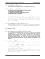
4.3.3 INITIATE A LOCAL LOOPBACK TEST OF THE MODEM (NOT UTC CONTROLLERS)
Use KME to get level 2 access and then set LTS=1. Check that the LTS display
indicates test running (LTS:2) and then test passed (LTS:0). For more
information on these handset commands, see section 6.1 on page 34.
This test is still applicable to installations where there is no modem installed and
the IMU is connected directly to a suitably configured GEMINI Bus Processor.
The Bus Processor emulates the modem provided that it has been configured to
operate a direct serial link to an IMU.
4.3.4 SWITCH TO THE CONTROLLER HANDSET COMMANDS
Entering ‘CON↵’ will switch the handset from the IMU to the controller.
Upon switching to the controller for the first time, a password is requested. When
the correct password is entered, the controller prompt “>” is displayed. The
default password is ‘ZZZZ’, but consult TCSU for the current password.
Entering ‘IMU↵’ will switch the handset from the controller to the IMU.
4.3.5 PERFORM NORMAL CONTROLLER COMMISSIONING SEQUENCE
If the Controller firmware and configuration have not been changed and only the
IMU has been be modified (i.e. replaced or upgraded), then the controller does
not need to be fully reset.
If the controller has been fully reset, then it must be commissioned in the usual
way. This should include any special configuration requirements, as detailed in
the works specification.
If the controller includes its own lamp monitor (e.g. T400 Intersection with Red
Lamp Monitoring or any ST700 or ST800) then this should be commissioned as
detailed in the relevant controller documentation.
Issue 05.00 – Page 28
Handbook for Siemens Integral Monitoring Unit
667/HB/22380/002
4.3.6 CHECK IMU CURRENT FAULT LOG
There should be no unexpected entries in the current fault log (FLC).
4.3.7 LOAD IMU SOFTWARE (NOT UTC CONTROLLERS)
Dial the IMU from the Instation and carry out the following:
a) Download the operating software
b) Load the correct time into the IMU and Controller
c) Download the IMU Configuration
d) Reset IMU to Operating Level 2 (i.e. the downloaded code is executed and
monitoring of the controller commences).
Note: The IMU will change automatically to operating level 2 once the call from
the Instation is terminated. During the change, the IMU will perform a restart,
which will re-initialise any maintenance terminal connection that was established
at that time. The handset command RIR can also be checked to indicate that the
IMU is in Level 2 (RIR:1).
4.3.8 CONFIRM IMU OPERATION (NOT UTC CONTROLLERS)
Re-dial the IMU from the Instation and confirm that the change to operating level
2 is reported and that there are no active faults. Terminate the call to the IMU.
4.4 COMMISSION THE IMU
4.4.1 SET COMMISSIONING FLAG ON IMU (NOT UTC CONTROLLERS)
The “Commissioning in Progress” Flag must be set on the IMU using the handset
command ‘CHK 2=1’. This is checked with the Instation as the IMU should dial
up and inform the Instation of the change. Once the call to the Instation is
completed, examine the entry in the current fault log to ensure that the NAK
indication has been removed. This shows that the call was successful as the
NAK indication is only removed when the fault has been acknowledged by the
Instation.
4.4.2 LAMP MONITORING (T400 ONLY)
Before entering KLR=1 to reset the IMU lamp monitor, check that all lamps are
on and working correctly.
Note that on an ST700 or ST800, the controller performs the lamp
monitoring and this should have been checked as part of the normal
controller commissioning procedure.
Reset the IMU Lamp Monitor (KLR=1).
Note: If the IMU is fitted to an Intersection T400 Controller with Red Lamp
Monitoring, ensure that the T400 Integral RLM card is functioning normally by
checking the controller fault log.
Issue 05.00 – Page 29
Handbook for Siemens Integral Monitoring Unit
667/HB/22380/002
Force the controller to cycle continuously and use the KAC or KES handset
commands (see section 6.5 on page 37) on the IMU to check that the lamp
currents and voltage are as expected.
After four controller cycles, use the KLS command to check that the LMU has
learnt the lamp loads. When all the lamp loads have been learnt, all the bits in
the KLS display will be cleared, i.e. KLS:00000000.
Note that if the site is fitted with dimming, then once the LMU has learnt the lamp
loads in either dim or bright, it will set Bit 3 to indicate that it is waiting for a
dim/bright changeover and hence commissioning is complete when the display
shows KLS:00001000.
Restore the Controller to normal demand operation.
4.4.3 LOCAL IMU DIGITAL INPUTS / OUTPUTS (NOT UTC CONTROLLERS)
If any of the four digital inputs on the IMU are used, then toggle the states of the
inputs and check, using the KDI command, that the IMU input port bits are
updated correctly.
If any of the four digital outputs on the IMU are used, then toggle the states of
the outputs using the DOP command and check that the IMU output lines
change state correctly.
See section 6.3 on page 36 for more information on these handset commands.
4.5 CLEAR IMU FAULT LOG
4.5.1 CLEAR COMMISSIONING FLAG (NOT UTC CONTROLLERS)
Before leaving site, the “Commissioning in Progress” flag must be cleared using
the CHK command (CHK 2 = 0). The IMU will then dial the instation to report this
change.
4.5.2 CHECK IMU FAULT LOG
Check the IMU current fault log (FLC) and ensure that there are no fault entries.
Issue 05.00 – Page 30
Handbook for Siemens Integral Monitoring Unit
667/HB/22380/002
5. MAINTENANCE
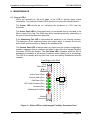
5.1 STATUS LED’S
LED’s are included on the front edge of the PCB to provide basic status
information. The position of these LED’s and their functions are detailed below…
The Power LED should be on, indicating the presence of +12V from the
Controller.
The Active Fault LED is illuminated when an uncleared fault is recorded in the
IMU’s current Fault Log. The OMU may still be operating normally; depending on
the type of failure that has been detected.
If the Watchdog Fail LED is illuminated the software is not running correctly.
The operation of the watchdog forces the output relays to release to the nonactive state and the modem to hang-up the telephone line.
The Comms Data LED is flashed when any data (such as modem configuration,
instation message data or loopback test data) is sent from the Integral Facilities
Processor PCB to the Modem. The Call State LED is flashed while the IMU is
attempting to establish a call with the instation (either dialling out or answering).
The LED is on steady while the IMU has a call successfully established with the
instation.
Front Edge of the PCB
PL4
(Not Used)
Active Fault (Red)
Comms Data (Grn)
Call State (Grn)
12V Power Present (Grn)
Reset
Switch
Unused (Grn)
Watchdog Fail (Red)
Modem
Connector
Figure 8 – Status LED’s on the Integral Facilities Processor Card
Issue 05.00 – Page 31
Handbook for Siemens Integral Monitoring Unit
667/HB/22380/002
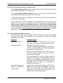
5.2 EFFECT OF INCORRECT SWITCH / LINK SETTINGS
If the Lithium Battery Switch (S2) is off the Active Fault LED will be illuminated
and the failure recorded in the Fault Log*.
If the Last Gasp Dial Battery Switch (S3) is off, the Active Fault LED will be
illuminated and the failure recorded in the Fault Log*.
* These faults will only be recorded in the Fault Log if the IMU is operating at
level 2 and is monitoring.
In the event that a modem is installed, if the modem power is set incorrectly (see
section 3.3.1) there are two possible outcomes. If the modem is being supplied
with a higher voltage it will probably work for a time, but the internal voltage
regulator may eventually go into thermal shutdown. If the modem is supplied with
a lower voltage than is nominally required, it may operate correctly. In both cases
of incorrect setting, correct operation of the modem is not guaranteed and BABT
approval for the Modem is invalidated.
5.3 FAULT FINDING AFTER INSTALLATION
The list below details some possible faults that may occur after the Integral
Monitoring Unit has been installed and commissioned, along with possible
remedies for the faults.
Symptom
Possible Reason
Active Fault LED On
Use the Handset to access the Fault Log for
information on the type of fault that has occurred.
Watchdog LED On
Software is not running correctly.
If the IMU cannot be accessed using the handset,
use the controller OMS and OMH commands to
record any error information.
Switch off the LGD battery and, if safe to do so,
turn the controller power off and on again to
restart the IMU software.
If the watchdog LED is still on, then Reset the
Processor and clear the IMU RAM by using a
suitable tool to depress the Reset Button on the
front edge of the PCB behind the LED’s. The IMU
operating code will need to be reloaded, as
described in section 3.7.7.
Inputs Not Functioning
Check Fuse protecting 24V supply on PCB (FS2)
Modem not Operating
Check Fuse protecting 8/12V supply to modem
(FS1) and check that the RS232 cable, the
Telephone Line and the Power connector to the
modem are all connected properly.
(where fitted)
Issue 05.00 – Page 32
Handbook for Siemens Integral Monitoring Unit
667/HB/22380/002
5.4 FUSES
The Integral Facilities Processor is fitted with three fuses (FS1, FS2 and FS3)
which are located just behind the Power and Local I/O Connector on the front
edge of the PCB (see
Figure 1 on page 13).
Fuse FS1 is used to protect the supply voltage to the modem. It is a 500mA
250V Quick Blow 20x5mm fuse - Part No: 518/4/90285/004
Fuse FS2 is used to protect the digital input supply. It is a 50mA 250V Quick
Blow 20x5mm fuse - Part No: 518/4/90285/000
The IMU may be fitted with an external fuse on the +12V supply. The external
fuse is included in the cableform that connects to PL5 from the Controller Power
supply. This fuse is rated at 3A, Part no: 518/4/90286/006
Fuse FS3 is also available to protect the +12v supply to the PCB without
requiring an external fuse. It is a 1.6A 250V Quick Blow 20x5mm fuse - Part No:
518/4/97023/009. If the on board fuse is used, the +12V supply should be
connected to pin 34 rather than pin 33 of connector PL5 (see Figure 6 on page
19).
5.5 LITHIUM BATTERY
The Integral Monitoring Unit is fitted with a Lithium Battery (B1 - Part No:
418/4/97186/000). The position of this battery is shown in see
Figure 1 on page 13.
The battery is dated on manufacture of the PCB and should be replaced six
years after the date shown on the label attached to the battery.
Warning:
Care should be taken when handling or disposing of Lithium Batteries. Refer to
Siemens Plessey Code of Practice CP526 for full instructions.
5.6 NICKEL-CADMIUM BATTERY
The Integral Monitoring Unit uses a Nickel-Cadmium Battery to provide power
when the mains’ power fails (Part Number 667/7/25176/000).
This battery is tested approximately every 30 days by the software and should be
replaced when a battery test failure is reported to the instation by the IMU (see
the BTT handset command).
Issue 05.00 – Page 33
Handbook for Siemens Integral Monitoring Unit
667/HB/22380/002
6. HANDSET COMMANDS
This section describes all of the IMU’s handset commands and identifies when the
commands are applicable.
The right-hand column shows the ‘access level’ of the handset command where R =
read only, O = open access, 2 = level 2 (enabled using KME).
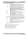
6.1 MISCELLANEOUS MAINTENANCE COMMANDS
BTT BTT : {1 to 254, or 0 or 255}
2
Number of days until the next Last Gasp Dial battery test. See section
6.8.1 on page 39. No function in TC8 mode since the battery is removed.
CHK CHK 1 = {0 or 1}
O
Set to ‘1’ to suspend all monitoring, including lamp monitoring. On an
ST700 or ST800, the controller continues to perform lamp monitoring but
the IMU will not pick up any lamp faults or replacements until monitoring
is re-enabled.
CHK CHK 2 = {0 or 1}
O
Set to ‘1’ to indicate “commissioning is in progress” to the instation
although monitoring by the IMU is unaffected. No function in TC8 mode.
CHK CHK 3 = {0 or 1}
O
Set to ‘1’ to suspend lamp monitoring. Has no effect on an ST700 or
ST800 since the controller performs lamp monitoring.
CON CON
O
Switch the handset to the controller. Also see the command “IMU”.
FLC FLC : fault log entry
R
Examine the IMU Current Fault Log. See section 6.8.5 on page 43.
FLH FLH : fault log entry
R
Examine the IMU Historic Fault Log. See section 6.8.5 on page 43.
IMU IMU
O
Switch the handset to the IMU. Also see the command “CON”.
KME KME = {0 to 255}
O
Controls ‘Level 2’ handset access.
LCP LCP {0 to 23} = {0 to 255}
2
Location for up to 24 ‘confirm signals’ for real time green updates, see
section 6.8.2 on page 40. No function in TC8 mode or on ST700 / ST800
controllers.
Issue 05.00 – Page 34
Handbook for Siemens Integral Monitoring Unit
667/HB/22380/002
LTS LTS : {0, 1, 2 or 255}
2
Modem Local Loop Back Test. Use “LTS=1↵” to manually request a test
on the modem. No function in TC8 mode since no modem is fitted.
LTS:1 – Test Requested
LTS:0 – Last Test Passed
LTS:2 – Test Running
LTS:255 – Last Test Failed
PIC
PIC : issue string
R
PROM firmware identity & issue.
RIC RIC : issue string
R
Downloaded (RAM) firmware identity & issue.
RIR
RIR : {0 or 1}
R
Running in RAM flag:
0 = IMU operating from PROM
1 = IMU operating from RAM.
TOD TOD
2
Shows/Sets the current date and time held in the IMU in the form “10JAN-94 12:15:30”.
Also allows the date to be set in TC-8 mode, e.g. “TOD=10JAN94”.
For test purposes only, the time may be set, e.g. “TOD=12:15:30”.
6.2 TC8 MODE HANDSET COMMANDS
TCE
TCE = {0 or 88}
2
TC-8 Mode Enable/Disable: 0 = IRM mode, and 88 = TC8 mode.
Starting or ending TC8 Mode causes complete re-initialisation of the IMU
firmware - fault logs, downloaded firmware and the current time and date
are all cleared.
TCM TCM = 1
2
TC-8 Mode - Enable Monitoring. Set to ‘1’ to enable monitoring.
TCR TCR = 1
2
TC-8 Mode - Reset fault log (clears all events from log).
Resets the ‘miscellaneous monitors’ causing controller fault log
monitoring and dim/bright checking faults to be cleared and only rereported when re-confirmed. Note that lamp monitoring is unaffected by
TCR.
Also see KDL, KDM and KDP in section 6.4) Lamp Supply Monitoring Commands.
Issue 05.00 – Page 35
Handbook for Siemens Integral Monitoring Unit
667/HB/22380/002
6.3 INPUT / OUTPUT HANDSET COMMANDS
DOP DOP {0 to 3} = {0 or 1}
2
Display/Change settings for the general purpose outputs where 1 is
active (closed circuit). No function in TC8 mode.
ICC
ICC {0-11} : integer
R
Displays the current count for each input counter. The first ‘n’ counters
are normally configured to monitor demands from the ‘n’ bus priority units
(if any). Note that the counters require a scaling factor set by the
instation. Only available with PB581 firmware on Intersections with
instation access (i.e. not TC8 mode).
ICL
ICL {0-11} = {0-95 / 255}
2
Displays/Changes the input counter’s input line number or 255 if the
counter is unused. Also see the command ICC.
KDI
KDI 0 : binary
R
Displays the IMU’s digital inputs (bit 0-3) and outputs (bits 4-7). No
function in TC8 mode.
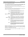
6.4 LAMP SUPPLY MONITORING COMMANDS
KDB KDB 0 : integer
R
Displays the dim/bright state: 0=undefined, 1=dim or 2=bright.
KDL
KDL = {0 to 255} (Default = 64)
2
Maximum dim/bright changes in 24-hour period. Only used in TC8 mode
since this is normally configured from the instation. A fault is recorded (at
the end of the 24-hour period) if the number of changes exceeds this
number. Note that this check is not disabled by KDP:0.
KDM KDM = {0 to 255} (Default = 1)
2
Minimum dim/bright changes in 24-hour period. Only used in TC8 mode
since this is normally configured from the instation. A fault is recorded if
this number is not reached. Note that this check is disabled by KDP:0.
KDP
KDP = { 0 or 1} (Default = As Controller Is Configured)
2
Controls whether dimming is present at this site. Only used in TC8 mode
to inform the LMU that dimming is not present at a UTC (TC8) site, since
this is normally configured from the instation. If dimming is not present,
the check for KDM is not performed and the LMU does not wait for a
dim/bright change when initially learning the lamp loads.
KEV
KEV : {Volts}
R
Displays the lamp supply voltage in volts. Not available with PB580 IMU
firmware, use KAC instead (see section 6.5).
Issue 05.00 – Page 36
Handbook for Siemens Integral Monitoring Unit
667/HB/22380/002
6.5 LAMP MONITORING COMMANDS – MAINTENANCE
KAC
KAC {1-23} {0-1} : integer
R
Displays ADC current and volts (in ADC counts) for each sensor, e.g.
KAC 3 0:50 (≈ 200mA ≈ 50W)
KAC 3 1:732 (≈240V).
The handset commands KES and KEV provide this information in ‘mA’
and ‘Volts’. These are available in PB581 IMU firmware, see below…
KAS
KAS {1 to 23} {0 to 6} : binary
R
Displays the lamp monitor aspect learn status for each current sensor
and aspect state (i.e. colour). See section 6.8.3 on page 41.
Use the controller handset command KAS on ST700 / ST800 controllers.
KES
KES {1 to 23} : mA + state
R
Displays the current in milliamps for each sensor. Also indicates ‘ON’ if
the phase monitored by the sensor is at green, otherwise it displays
‘OFF’. For sensors monitoring wait lamps, ‘ON’ indicates that the wait is
illuminated.
Not available with PB580 IMU firmware, use KAC instead. Use the
controller handset command KES on an ST700 / ST800 controllers.
KEV
See section 6.4) Lamp Supply Monitoring Commands on page 36.
KLM KLM 0 : {integer}
R
R
Displays: 6 = Lamps Off, 7 = Lamps On, and 8 = change in progress.
KLR
KLR = 1
2
Request lamp monitor reset and re-learn by entering “KLR=1”. This
command must always be used after changing the LMU configuration
using the handset. This command does not reset the controller lamp
monitor.
KLS
KLS : binary
R
Lamp monitor overall learn status. Section 6.8.3 on page 41 details the
bits. Use the controller handset command KLS or KML on ST700 / ST800
controllers.
LMR LMR {1 to 5} {A to P}
R
Displays the record for the given ‘fault level’ (1-5) and phase (A-P) from
the current profile store, see section 6.8.4 on page 42. On T400 pelicans,
phases A and B apply to the first pelican and phases E and F to the
second pelican of a dual.
Not available with PB580 IMU Firmware nor on ST700 / ST800
controllers. On ST700 / ST800 controllers, use the controller command
KEL which shows the learnt load in watts.
Issue 05.00 – Page 37
Handbook for Siemens Integral Monitoring Unit
667/HB/22380/002
6.6 LAMP MONITORING COMMANDS – CONFIGURATION
Note that these IMU handset commands are ignored on ST700 / ST800 controllers
since the controller is performing the lamp monitoring, not the IMU…
KAD KAD {1 to 23} = {0 to 255} (Default from Controller Configuration)
2
Aspect drives for each current sensor, where 0 = Phase A, 1 = Phase B
and 15 = Phase P. For sensors monitoring green arrows, add 32 to these
values.
KLC
KLC = {1 to 255} (Default = 60)
2
Lamp monitor ‘confirm time’ in seconds. Only used in TC8 mode since
this limit is normally configured from the instation.
KLE
KLE = {0 or 1} (Default = 1)
2
LMU enabled (KLE:1) or disabled (KLE:0).
Note that the IMU handset command CHK3 (on page 34) should be used
in preference to using KLE=0 to disable the lamp monitor facility.
KPT
KPT {1 to 23} = {0 to 255} (Default from Controller Configuration)
2
Phase types for each current sensor:1: Intersection Vehicle Phase
2: MCE125 Vehicle Phase (flashing amber)
3: Intersection Pedestrian Phase
4: MCE125 Ped Phase (flashing green man)
5: 40 Watt Wait Indicators
6: 60 Watt Wait Indicators
8: Switched Bulb (used for Green Arrows)
255: Sensor Not Used
6.7 ENGINEERING HANDSET COMMANDS
KDC KDC {0 to 3} = {0 to 255} ........................................ Dummy routine control
KEB
2
KEB = {0 to 2} ..................................................... Engineering display base O
KEG KEG {0-N} {0-255} : {0-255}..........Display/Change engineering data items
2
KER KER {0-FFFFF} : {0-255} .............. Display/Change engineering RAM data
2
KFE
KFE {0-3} = {0-100} .................................................% Processor free time
2
KPU
KPU {0 to 5} = {0 to 255} .....................................................Power up data
2
KRT
KRT {0 to 7} = {0 to 255}........................................ Run time monitor items
2
KSC
KSC : Integer ......................................................... Soft error current count R
OMH OMH : Integer ....................................................................Hard error code R
OMS OMS {0 to 2} : Hex............................................................ Soft error codes R
Issue 05.00 – Page 38
Handbook for Siemens Integral Monitoring Unit
667/HB/22380/002
6.8 ADDITIONAL INFORMATION ON CERTAIN HANDSET COMMANDS
6.8.1 BATTERY TEST TIME (BTT)
BTT [ = {0, 1 to 254, or 255} ]
Displays the time interval remaining (in days) before the next battery test for the
LGD battery and can be used to force an immediate test or battery discharge
cycle.
The battery test time will be 1.5 hours during which time the BTT command will
show ‘0’. When the IMU has completed the test, the battery will be discharged to
avoid any “memory” effect. The battery will be discharged for 3.5 hours (giving 5
hours total discharge time), or until the battery voltage has dropped below the
test threshold.
The last battery discharge time will be stored in the IMU and made available to
the operator via the KEG command (KEG 30 0). This will show the discharge
time in minutes (i.e. the normal 3.5 hour discharge time would be displayed as
210 minutes).
During the battery discharge period, the BTT command will show ‘255’. Once the
battery discharge is complete, the BTT command will return to ‘30’, i.e. the
number of days to the next battery test.
If a battery test is invoked manually, by the operator setting BTT to 0, then the
1.5 hour test is carried out as normal. However, at the end of the test no battery
discharge is started and the BTT display returns to ‘30’.
If the operator sets the BTT command to 255, then the battery discharge cycle is
invoked.
Setting the BTT command to any other value (i.e. 1 to 254) aborts a battery test
or discharge cycle which may have been in progress and the IMU will perform
the next automatic battery test after the set number of days (as entered by the
operator). The BTT value would normally be set to 30 to resume the standard
battery test interval.
Issue 05.00 – Page 39
Handbook for Siemens Integral Monitoring Unit
667/HB/22380/002
6.8.2 GREEN STATE LOCATIONS (LCP)
The values used for the phase location handset command (LCP) identify which
colour of which phase is to be returned to the instation during real time green
update. The items are returned in the order in which they are defined in the LCP
list. This handset command allows the engineer to alter the default settings that
the IMU obtained from the controller. Note that this command is ignored on
ST700 / ST800 controllers.
The basic values are as follows:
• the values 0 to 15 identify the red colour on the 16 phases A to P,
• the values 16 to 31 identify the amber colour on the 16 phases A to P,
• the values 32 to 47 identify the green colour on the 16 phases A to P,
• the value 255 marks the end of the list (see the example below).
If the colour flashes (e.g. flashing amber or green man) then three options exist:
• ‘True Lamp State’ - the real lamp state is sent to the instation so that the
instation will ‘see’ the colour turning off and on repeatedly - use the numbers
above,
• ‘Flashing as ON’ - during the flashing period, the instation will just see that the
colour is on and so is indistinguishable from the steady state - add 100 to the
numbers above (to give 100-115,116-131,132-147),
• ‘Flashing as OFF’ - during the flashing period, the instation will not see that
colour on (a flashing amber will not be seen while a green man will appear to
end when it starts to flash) - add 200 (to give 200-215,216-231,232-247).
For example, the default settings for a single pelican are:
LCP 0:32
Phase A green (vehicle green)
LCP 1:233 Phase B green with flashing as OFF (steady green man only)
LCP 2:2
Phase C red (audio confirm indictor on T400)
LCP 3:255 End of List Marker - only 3 phases are to be sent to instation.
In addition, the following values will be defined for the second stream on a dual
pelican:
LCP 12:36 Phase E green (vehicle green)
LCP 13:237 Phase F green with flashing as OFF (steady green man only)
LCP 14:6
Phase G red (audio confirm indictor on T400)
LCP 15:255 End of List Marker - only 3 phases are to be sent to instation.
Issue 05.00 – Page 40
Handbook for Siemens Integral Monitoring Unit
667/HB/22380/002
6.8.3 LEARN STATUS BITS (KAS AND KLS)
Bit 0
AWAIT_DIM - Aspect not yet appeared in DIM:
This bit is set if the current state is known to be Bright and
Await_Dim_Change is set. It is cleared when dim / bright
state is dim and Await_Dim_Change is clear.
Bit 1
AWAIT_BRIGHT - Aspect not yet appeared in BRIGHT:
This bit is set if the current state is known to be Dim and
Await_Dim_Change is set. It is cleared when dim / bright
state is bright and Await_Dim_Change is clear.
Note: Under certain conditions both Await_Dim and
Await_Bright can be set for an aspect. If this occurs neither
bit will be cleared until the LMU has learnt the aspect in both
dim and bright states.
Bit 2
AWAIT_ASPECT - Aspect not yet appeared:
Set on LMU Initialisation. Cleared when aspect is first learnt.
Bit 3
AWAIT_DIM_CHANGE - First Dim / Bright Change
assessment enabled:
Set on LMU Initialisation if dim / bright changeover
monitoring is enabled. Cleared after the first dim / bright
change assessment for the aspect has been completed.
The following bits are only set in the KAS display and not the KLS display:
Bit 4
CONF_LOAD - Aspect being assessed for load change:
Set when either the ‘rise’ or ‘fall’ load change counter is nonzero. Cleared when both the ‘rise’ and ‘fall’ load change
counters are zero. (KAS only)
Bit 5
CONF_DIM - Aspect being assessed for dim / bright
change:
Set when either the ‘dim’ or ‘bright’ load change counter is
non-zero. Cleared when both the ‘dim’ and ‘bright’ load
change counters are zero. (KAS only)
Bits 6 & 7
Not Used
The aspect states for each type of sensor are listed here:
Vehicle Phases: 0=Red, 1=Green, 2=Amber
Pedestrian Phases: 0=RedMan, 1=GreenMan
Wait Indicators: 0=LampsOff, 1=LampsOn
Green Arrows: 0=LampsOff, 1=LampsOn
Issue 05.00 – Page 41
Handbook for Siemens Integral Monitoring Unit
667/HB/22380/002
6.8.4 CURRENT PROFILE STORE (LMR)
The LMU keeps a ‘current profile store’ for all the lamp currents of the controller.
The store consists of five ‘levels’ starting at level 1. Level 1 of the current profile
initially holds the present currents of all the lamps and is marked as ‘No Fault (no
more levels)’. To view all the currents, enter ‘LMR 1 A’ and then use the ‘+’ key
to scroll through the list.
When the LMU confirms a lamp fault (or colour conflict), it records the current
from before the failure occurred in level 1 of the current profile and marks that
level with either ‘Fault (see next level)’ or ‘Conflict (see next level)’. In other
words, the currents in level 1 remain at the initial level, i.e. are ‘frozen’ and the
status changed to indicate that a fault has occurred. Now level 2 will show a
status of ‘No Fault (no more levels)’ and the new present current, which will be
lower in the case of lamp failure and higher in the case of a colour conflict.
For example:
LMR 1 A: Fault
(see next level) R:0.51 A:0.52 G:0.50 W:-.-LMR 1 B: No Fault (no more levels) R:-.-- A:-.-- G:0.26 W:-.-LMR 1 C: Conflict (see next level) R:0.51 A:-.-- G:0.50 W:0.40
LMR 2 A: No Fault (no more levels) R:0.25 A:0.52 G:0.24 W:-.-LMR 2 B: No Fault (no more levels) R:-.-- A:-.-- G:0.26 W:-.-LMR 2 C: No Fault (no more levels) R:0.51 A:-.-- G:1.01 W:0.40
In this example, Phase A is a vehicle phase with lamp failures on both red and
green. Phase B is a green arrow (hence no red or amber currents). Phase C is a
pedestrian phase with a large current increase (colour conflict) on the green man
(e.g. the red man is stuck on).
Note that failures on different colours of the same phase are ‘combined’ in the
same level (see phase A). If the failure on the green had been a colour conflict
(current increase), then the fault status would show ‘Conflict’ and not ‘Fault’ since
the fault status displayed is for the last colour with a fault reading left to right, and
so the fault status for the green is shown.
If a second lamp failure (or colour conflict) is confirmed on the same phase and
colour, the currents in level 2 are ‘frozen’ and the status changed accordingly.
Now level 3 will show the new even lower (or higher) current. This process
continues until level 4 indicates a fault. After that, no more ‘old’ currents are
stored and level 5 always shows ‘No fault (no more levels)’ and the present
currents.
Issue 05.00 – Page 42
Handbook for Siemens Integral Monitoring Unit
667/HB/22380/002
6.8.5 FAULT LOG COMMANDS (FLC AND FLH)
The current fault log contains entries for currently active faults (and those events
not yet reported to the instation). If the IMU is running firmware PB580 in TC8
mode, events remain in the current fault log until cleared by TCR=1.
The historic fault log holds all fault occurrences and clearances and all events in
the order that they occurred.
There are three alternative ways of initially entering the handset commands that
display the current and historic fault log as described below:
FLC
Entering the command with no index displays the most
recent entry from the current fault log.
FLH
Entering the command with no index displays the most
recent entry from the historic fault log.
FLC n
On entering “FLC n”, entry number “n” from the current
fault log is displayed, where 0 is the most recent entry
and 31 is the oldest. If the log is not full, entering FLC
31 will display the oldest existing entry in the current
fault log.
(where n = 0 to 31)
FLH n
(where n = 0 to
255)
On entering “FLH n”, entry number “n” from the historic
fault log is displayed, where 0 is the most recent entry
and 255 is the oldest. If the log is not full, entering FLH
255 will display the oldest existing entry in the historic
fault log.
FLC ?
The entry being viewed when the FLC command was
last used is re-displayed. This allows the user to use
other handset commands and then re-enter the fault
log at the same point.
FLH ?
The entry being viewed when the FLH) command was
last used is re-displayed. This allows the user to use
other handset commands and then re-enter the fault
log at the same point.
Whichever command option is used, the “+” key can be used to step back
through the log, displaying older entries. When the end of the log is reached,
using the “+” key re-displays the last entry. The “-” key can be used to step
forward again, displaying more recent entries.
The fault log command will return “FAULT LOG IS EMPTY” if there are no
entries to be displayed.
Issue 05.00 – Page 43
Handbook for Siemens Integral Monitoring Unit
667/HB/22380/002
The display format which is used for the maintenance terminal connected to the
IMU is:
DD-MMM-YY HH:MM:SS Code:F/C <fault entry text> NAK
where:
DD
MMM
YY
HH
MM
SS
F/C
<fault entry text>
NAK
=
=
=
=
=
=
=
=
=
day of month: 00 to 31
month: JAN, FEB etc.
year: 00 to 99 (99 = 1999, 00 = 2000 etc.)
hours: 00 to 23
minutes: 00 to 59
seconds: 00 to 59
Fault Code 1 to 255 as defined by TCSU
Text description of fault, see below
‘NAK’ for an unacknowledged fault or blank.
The report for a red lamp fail on the vehicle phase of the first pelican, where this
report has not yet been acknowledged by the instation, would therefore appear
as follows:
10-MAR-93 08:44:03 Code 41: Lamp failure - vehicle red, ctlr 1 NAK
A complete list of fault log codes and displays is given in section 6.9 starting on
page 45.
Issue 05.00 – Page 44
Handbook for Siemens Integral Monitoring Unit
667/HB/22380/002
6.9 FAULT DISPLAY CODES AND TEXT
This section contains all the fault log codes and associated text, as seen when
using the FLC and FLH commands.
The variable values used in the reports are explained below:
The new operating level:level ‘n’
1 = running from PROM
2 = running from downloaded code in RAM
‘colour’
The failed lamp colour: Red, Amber, Green, or Wait.
Phase ‘x’
The phase on which the colour has failed (Phases A to P)
The controller reference:ctlr ‘n’
1 = first pelican, 2 = second pelican of a dual
Changes=‘n’ The number of dim/bright changes in the 24-hour period.
The failed detector number (controller input line number 0
line ‘n’
to 95).
Maintenance flag number:1 = monitoring suspended
CHK ‘n’
2 = monitoring enabled (but commissioning in progress)
3 = lamp monitoring suspended
The IMU general-purpose digital input number, range 1 to
Input ‘n’
4.
stream ‘n’
Stream number where ‘n’ denotes stream 0 onwards.
This table details the Fault codes and the text associated with the faults. Note
that the inverted commas shown around ‘n’ and ‘x’ etc. in the tables are for clarity
and are not displayed on the handset.
Code
Code
Code
Code
Code
Code
Code
Code
Code
Code
Code
Code
Code
Code
Code
Code
Code
Code
Code
Code
Code
Code
Code
Code
1
3
5
6
9
11
13
15
16
15
16
17
18
17
18
17
18
21
23
25
27
29
31
39
IMU has been reset to level ‘n’
Lamp monitor has been reset
IMU is not monitoring (TCM:0)
IMU is running normally (TCM:1)
Controller has been reset to PROM
Controller fault log has been reset
Detector monitor has been reset
Telephone communications fault
Telephone communications fault clear
Modem configuration fail
Modem configuration successful
Link level communications failure
Link level communications failure cleared
Periodic local loopback test failed
Periodic local loopback test passed
Bad message received
Bad message fault cleared
IMU RAM configuration area sum check fail
IMU RAM instruction area sum check fail
IMU PROM instruction area sum check fail
Software logical check fail (soft error)
Watchdog check fail
Miscellaneous monitor has been reset
Outstanding fault in log
Issue 05.00 – Page 45
Handbook for Siemens Integral Monitoring Unit
Code
Code
Code
Code
Code
Code
Code
Code
Code
Code
Code
Code
Code
Code
Code
Code
Code
Code
Code
Code
Code
Code
Code
Code
Code
Code
Code
Code
Code
Code
Code
Code
Code
Code
Code
Code
Code
Code
Code
Code
Code
Code
Code
Code
Code
*
†
‡
40
41
41
41
42
42
42
43
43
43
44
44
44
45}*
46}
59}†
60}
61
62
63
64
65
66
65
66
67
68
69
69
70
70
71
72
131
132
133
134
135
139}‡
140}
139}
140}
141
141
141
667/HB/22380/002
Outstanding fault cleared
Lamp failure - veh ‘colour’ - ctlr ‘n’
Lamp failure - ped ‘colour’ – ctlr ‘n’
Lamp failure - phase ‘x’, ‘colour’
Lamp replaced - veh ‘colour’ – ctlr ‘n’
Lamp replaced - ped ‘colour’ – ctlr ‘n’
Lamp replaced - phase ‘x’, ‘colour’
Colour conflict - veh ‘colour’ – ctlr ‘n’
Colour conflict - ped ‘colour’ - ctlr ‘n’
Colour conflict - phase ‘x’, ‘colour’
Colour conflict clear - veh ‘colour’ - ctlr ‘n’
Colour conflict clear - ped ‘colour’ - ctlr ‘n’
Colour conflict clear - phase ‘x’, ‘colour’
Undecided lamp failure – phase ‘x’
Undecided lamp fail clear – phase ‘x’
Lamps off, 2nd RL fail, stream ‘n’
Lamps on, 2nd RL fail - clear, stream ‘n’
Lamp supply failed, ctlr ‘n’
Lamp supply restored, ctlr ‘n’
Mains power failed
Mains power restored
LGD battery supply failed
LGD battery supply restored
RAM battery supply failed
RAM battery supply restored
Dimmer sequence failed: Changes = ‘n’
Dimmer sequence restored: Changes = ‘n’
Veh detector DFM fail - line ‘n’
Ped push-button DFM fail - line ‘n’
Veh detector DFM restored - line ‘n’
Ped push-button DFM restored - line ‘n’
Audio tone inoperable fault
Audio tone inoperable fault clear
FLF nn: ‘Controller FLF fault’
FLF nn: ‘Controller FLF fault’ - clear
Controller communications failed
Controller communications restored
Controller invalid reply
Controller time check failed
Controller time failure cleared
Clock fault - IMU is ‘fast by HH:MM:SS’
Clock fault - cleared
Controller clock data changed
Controller fixed veh periods changed
Controller min times changed
‘Undecided lamp faults’ are only reported on ST800 Controllers when the Controller
and the IMU are unable to determine whether the confirmed lamp fault is a pedestrian
red lamp or a pedestrian wait lamp.
Indications of ‘Lamps off due to second red lamp failures’ are not provided before
T400 firmware PB322 issue 7 and IMU firmware issue 2.
PB581 firmware displays the time discrepancy held within the fault data. PB580
firmware did not.
Issue 05.00 – Page 46
Handbook for Siemens Integral Monitoring Unit
Code
Code
Code
Code
Code
Code
Code
Code
Code
Code
Code
Code
Code
Code
Code
Code
Code
Code
Code
Code
Code
Code
Code
Code
Code
Code
Code
Code
Code
Code
Code
Code
Code
Code
Code
Code
Code
Code
Code
Code
Code
Code
Code
Code
Code
Code
Code
Code
141
141
141
141
141
141
141
141
141
141
141
141
141
141
141
141
141
141
141
141
141
141
141
141
141
141
141
141
141
141
141
141
141
141
141
141
141
141
141
141
141
141
149
150
151
152
153
154
667/HB/22380/002
Controller max times changed
Controller ext times changed
Controller all red times changed
Controller ped green times changed
Controller phase delay periods changed
Controller ped black-out changed
Controller conditioning timers changed
Controller intergreen times changed
Controller misc intergreen data changed
Controller SDE/SA data changed
Controller hurry delay periods changed
Controller hurry hold periods changed
Controller hurry prevent periods changed
Controller call delay periods changed
Controller cancel delay periods changed
Controller bus extension periods changed
Controller bus maximum periods changed
Controller bus inhibit periods changed
Controller bus priority demands changed
Controller bus revertive demands changed
Controller bus revertive inhibits changed
Controller bus allowed VA demands changed
Controller bus enforced demands changed
Controller bus compensation data changed
Controller bus miscellaneous data changed
Controller detector data changed
Controller timetable data changed
Controller plan 0 data changed
Controller plan 1 data changed
Controller plan 2 data changed
Controller plan 3 data changed
Controller plan 4 data changed
Controller plan 5 data changed
Controller plan 6 data changed
Controller plan 7 data changed
Controller plan miscellaneous data changed
Controller fault log reset
Controller DFM reset
Controller plan influence data changed
Controller fixed time data changed
Controller general data changed
Controller local link data changed
Site engineer logged on - CHK ‘n’
Site engineer logged off - CHK ‘n’
Input monitor alarm - Input ‘n’
Input monitor alarm clear - Input ‘n’
Input monitor overload
Input monitor overload clear
Issue 05.00 – Page 47