1
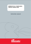
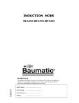
GAS HOBS
USER AND INSTALLATION
INSTRUCTIONS
B72TCBL-BX
B72BL
B77TCBL-BX
B77BL
AS9.1TCAL-BX
AS9.1AL
INSTALLATION INSTRUCTIONS
For future reference please record the following information which can be
found on the Rating Plate and the date of purchase which can be found in the
invoice:
Model Number
…………………….
Serial Number
…………………….
Date of Purchase
…………………….
CONTENTS
General Information
page 3
Warning and Safety Instructions
page 4
Instructions for Use
Instructions for Installation
Technical Data
Conditions of Guarantee
2
pages 4-6
Pages 6-10
Pages 10
Back cover
INSTALLATION INSTRUCTIONS
GENERAL INFORMATION
Please read this booklet thoroughly before you use this appliance. It is important that you
understand all the control functions before commencing to cook with your Baumatic appliance.
Please remember the advice and warnings shown on page 4, which is headed
‘IMPORTANT – Warning and Safety Instructions’.
This appliance is designed for domestic household use when built into a kitchen worktop.
NOTE: The housing, adjacent furniture and all materials used in the installation must be able to
withstand a minimum temperature rise of 85°C above ambient during periods of operation. This
information is for guidance only and the actual withstand temperature will depend on the
performance rating for the surface finish of the worktop.
Certain types of kitchen furniture surface finishes are particularly prone to heat damage or
discoloration at temperatures lower than the above guidelines.
Installing the appliance in contravention of the guidance given, will be at the liability of the
owner.
For use in Leisure Accommodation Vehicles, notice must be taken of the appropriate statement in
the Installation Instructions (see page 7 – Important Note 5).
The use for any other purpose or in any other environment without the express agreement of
Baumatic Ltd, would invalidate any warrantee or liability claim
Your new appliance is guaranteed against electrical or mechanical defects subject to certain
exclusions noted in Baumatic Ltd Conditions of Guarantee.
The aforegoing does not affect your statutory rights.
The Warrantee applies to Great Britain and Northern Ireland only.
In the event that you require any After Sales Service or advice, please contact the Baumatic
Service Department on telephone number – 0118 933 6911.
Before using this appliance ensure that any protective packaging or coatings have been removed.
To aid the protection of the environment, please sort the packing materials into different types
and dispose of them in accordance with the local waste disposal laws.
Any further information can be obtained from your local Environment Agency office.
When first used, an odour may be emitted by any residual protective finish or moisture, which
will cease after a short period of time.
This appliance has been constructed and distributed in compliance with the essential requirements
of the following EEC DIRECTIVES and EUROPEAN NORMS :CE Marking – 93/68 Low Voltage – 73/23 Gas Products – 90/396
Materials that can touch food – 89/109.
Safety Standards – EN 60 335-1, EN 60 335 – 2 – 6, EN 30-1-1.
EMC – 89/336
As Baumatic have a policy of continued product improvement, the right is reserved to adjust and
make any modifications deemed necessary without notification.
3
INSTALLATION INSTRUCTIONS
IMPORTANT NOTE – WARNING and SAFETY INSTRUCTIONS
This appliance complies with all current European safety legislation, however Baumatic do wish
to emphasise that compliance does not remove the fact that surfaces will become hot during use
and retain heat after operation.
Baumatic therefore strongly advise that babies and young children are prevented from being near
or touching the appliance at any time.
If it is necessary for younger family members to be in the kitchen, that they are kept under close
supervision at all times.
We also advise that great care is taken during use and cleaning operations.
Do make sure that the pan handles are always correctly positioned to avoid accidental contact.
Do not leave heated oil or fat unattended as there is a risk of fire.
Do use pans that are flat bottomed and the correct size for the heating area to be used (never
smaller).
Do not allow electrical fittings or cables to be in contact with hot areas of the appliance.
Do not use the appliance for space heating or to dry clothes.
Do not install the appliance next to curtains or soft furnishings.
NOTE: This appliance must be correctly installed by a suitably qualified person, strictly in
accordance with the manufacturer’s instructions. For gas installations, the Installer must be
Corgi registered (all Baumatic Engineers are Corgi registered) and for electrical
installations, NICEIC registration is recommended.
Baumatic Ltd declines any responsibility for injury or damage to persons or property as a
result of improper use or installation of this appliance.
Heat, steam and moisture will be created during use, take care to avoid injury and ensure
that the room is adequately ventilated. If prolonged use occurs, additional ventilation may
be required – please consult your Qualified Installer if you are in any doubt about the
amount required.
INSTRUCTIONS FOR USE
These User Instructions should be retained for future reference and for use by a person who is
perhaps unfamiliar with the appliance.
The following models are covered by these instructions:
AS9.1TCAL-BX
B72TCBL-BX
B77TCBL-BX
4
INSTALLATION INSTRUCTIONS
USING THE HOB
The symbols on the Control Panel fascias show which burner the Control Knob operates.
Dependent on the model there are two methods for igniting the burners.
1. Auto Ignition
After pressing in and turning the appropriate knob anti-clockwise to the large flame symbol,
the ignition spark will operate as long as the knob is pressed down..
When a flame has been established the knob can be released.
2. Manual Ignition
After pressing in and turning the appropriate knob anti-clockwise to the large flame symbol,
press the ignition button located on the control panel.
The ignition spark will operate as long as the button is held down. When a flame has been
established, release the button.
To regulate the flame, continue turning anti-clockwise to the required setting between the large
and small flame symbols.
To turn the burner off, turn fully clockwise.
NOTE:
When a Thermocouple Safety Device is incorporated in the appliance, it is necessary for the knob
to be continuously held down for a further period of approximately 10 seconds after the flame has
been established to enable the thermocouple to function.
The Safety Device is designed to stop the flow of gas to the burner head in the event of a flame
out situation.
HELPFUL HINTS
Always use the correct diameter pan, one that is the same or slightly larger than the flame ring.
The flame should never exceed the diameter of the pan.
The bottom of the pan should be flat and wherever possible, keep the lid on the pan when
cooking.
Depending on the model the following burners are provided:
Large (Rapid or Triple Crown) – for rapid cooking or boiling large quantities of liquid
Wok – for rapid cooking or boiling large quantities of liquid
Medium (Semi-rapid) – for general cooking
Small (Auxiliary)– for slow or simmer cooking
Fish Kettle – for specialised cooking
All burners are variable between full and low positions
WARNING
Do not use commercial simmering aids as these can create excessive heat, which can damage the
appliance.
5
INSTALLATION INSTRUCTIONS
CLEANING THE APPLIANCE
Always allow the appliance to cool down before cleaning to avoid a burn injury.
Do not use caustic or abrasive agents, coarse wire wool or hard tools as these can damage the
surface finishes.
Normally, wiping with a soft cloth dampened with hot detergent solution is sufficient but for
stubborn marks the following is recommended:
Vitreous Enamel parts – use only a cleaner that is recommended for this type of material.
Burner Assemblies – remove from the hob and soak for about 10 minutes in hot detergent
solution. Rinse off and dry checking that the burner holes are not clogged, then reassemble in the
correct order.
INSTRUCTIONS FOR INSTALLATION
This appliance must be installed by a competent person in accordance with the current
versions of the following UK (United Kingdom) or ROI (Republic of Ireland)
Regulations and Safety Standards or their European Norm Replacements.
Irish Standard for Domestic Gas Installations
NOTE: UK law stipulates that gas appliances must be installed and repaired by a CORGI
Registered Installer (all Baumatic Engineers are CORGI Registered).
Gas safety Regulations (Installation & Use)
Building Regulations (issued by the Department of Environment)
Building Standards (Issued by the Scottish Development Department)
IEE Wiring Regulations
Electricity at Work Regulations
BS 6172 Installation of Domestic Gas Cooking Appliances
(if necessary, BS 5482 Installation of Domestic LPG Appliances)
BS 5440 Installation of Flues and Ventilation for Gas Appliances
Baumatic Ltd Installation Instructions
POSITIONING THE APPLIANCE
This appliance is classified as Class 3 and therefore is to be built into a kitchen unit (depending
on size) or 600mm wide worktop, providing the following minimum distance is allowed:
- 700mm between the top surface and the underside of any horizontal surface above it.
- 50mm clearance around the appliance and combustible materials.
The surface finish of any adjacent unit must be capable of withstanding a minimum temperature
of 85°C.
PRE-COMMISSIONING THE APPLIANCE
When unpacked, check that the following parts are included with the appliance:• Baumatic Ltd Instruction and Installation Book
• Pan Supports
• Burner Assemblies
• Adhesive sealing strip and fixing clamps & screws
• ½ BSP Elbow & Seal
• LPG conversion kit comprising an LPG jet for each burner and a self-adhesive label for
amending Gas Category on the appliance Rating Label.
6
INSTALLATION INSTRUCTIONS
INSTALLATION NOTES
1. Cut the aperture to the dimensions shown below or use the template if printed on the
packaging.
2. Invert the Hob and apply the sealing agent provided to match the outer perimeter edge.
3. If the sealing agent is a strip type, the protective covering must be removed from both sides.
Do not leave a gap in the sealing agent or overlap the thickness.
NOTE: do not use any Silicone based sealant, as this can damage the worktop surface if
repairs are required.
4. Insert the appliance into the aperture and fix in position via the clamps & screws, tightening
the screws evenly (see Fig. 1 below).
5. If the appliance is to be installed in a Leisure Accommodation Vehicle, the requirements of
EN 721 must be applied.
Fig. 1
HOB APERTURE DIMENSIONS
MODEL
A
B
C
D
580 510 565 492
B72TCBL-BX
680 510 560 480
B77TCBL-BX
AS9.1TCAL-BX 680 510 560 480
E
50
50
50
7
INSTALLATION INSTRUCTIONS
VENTILATION OF ROOMS
The room in which this appliance is installed must be well ventilated by natural or mechanical
means, or a combination of both to ensure correct combustion and the removal of spent air.
The minimum quantity of air for combustion will depend on the room volume, number of
appliances and their total power rating.
The power rating of your appliance can be found by reference to the Rating Plate.
Note: The actual ventilation requirements must be determined by reference to the Statutory
Regulations in force.
GAS CONNECTION
The gas supply must be connected by use of the ½ BSP Elbow, Seal and copper pipe and an
isolation tap fitted in an easily accessible position.
The appliance as supplied is for use with Natural Gas, if it is to be adapted for LPG proceed as
follows:
• Isolate the appliance from the electricity and gas supplies.
• Remove the pan supports and burner assemblies.
• Replace the injectors with the alternative type supplied.
• Use the appropriate thread sealant and check for gas soundness.
• Affix the self-adhesive label to the Rating Plate to amend the Gas Category.
Fig 2
Fig 3
GAS FLOW ADJUSTMENT
In order to adjust the minimum gas flow proceed as follows:
• Ignite the burner and turn down to the minimum setting.
• Remove the control knob from the gas tap.
• Adjust the flow either clockwise to decrease or anti-clockwise to increase the flame. Use a
screwdriver inserted down the gas tap rod or via the screw head adjacent to the rod for
models fitted with a Flame Supervision Device.
• Check that the flame is 3- 4 mm in length, bluish in colour, stable and noiseless, and does not
extinguish when changing from maximum to minimum flow.
• Replace the control knob and check that all components have been reassembled correctly.
8
INSTALLATION INSTRUCTIONS
ELECTRICAL CONNECTION
Before connecting the appliance, make sure the supply voltage marked on the rating Plate
corresponds with the mains supply voltage.
WARNING – THIS APPLIANCE MUST BE EARTHED
This appliance should be wired into a double pole Switched Fused Spur Outlet having 3 mm
contact separation and the fuse rating reduced to 3 Amps.
IMPORTANT
The wires in the main supply lead are coloured in accordance with the following code:Green and Yellow
– Earth
Blue
– Neutral
Brown
– Live
The connections must be made as follows:The wire coloured Green and Yellow must be connected to the terminal marked ‘E’ or the earth
symbol (⊥) or coloured green and yellow.
The wire coloured Blue must be connected to the terminal marked ‘N’ or coloured blue or Black.
The wire coloured Brown must be connected to the terminal marked ‘L’ or coloured brown or
red.
NOTE: The terminals marked ‘SUPPLY’ are for the mains supply wires and the terminations
marked ‘LOAD’ are for the appliance wires.
The electrical outlet is to be positioned in an easily accessible position adjacent to the appliance.
In the event that it is necessary to replace the mains supply lead, the replacement must conform to
the specification listed in the Technical Data. Ensure that the colour code connection is correct
and that all screws are tightened correctly.
MAINTENANCE
During the guarantee period, in case of need all service intervention should be referred
back to the Baumatic Ltd Service department. Please note that intervention or repair by
any unauthorised personnel will invalidate such guarantee,
Before carrying out any maintenance, disconnect the appliance from the gas and electricity
supplies.
If a gas tap becomes stiff to operate, proceed as follows:
• Remove the control knobs, pan supports, burners and hob fixing screws & clamps.
• Remove the Hob from the worktop and remove any underside protective covers.
• Disconnect the fixings holding the tap to the fascia panel, separate the assembly, then clean
the cone and seating with a cloth dampened with solvent.
• Lightly smear the cone with high temperature grease, reassemble into position and rotate a
few times. Remove the cone again and remove any excess grease making sure that the gas
ducts are not obstructed with grease.
• Carefully reassemble the components and check for gas soundness.
9
INSTALLATION INSTRUCTIONS
If it becomes necessary to replace the gas tap, proceed as follows:
• Disconnect the appliance as described above.
• Disconnect the gas pipe from the gas tap, disassemble from the gas rail by removing the
fixing screws.
• When fitting a new tap, ensure that a new gasket is used.
• Re-connect the gas tap, check for gas soundness and reassemble the hob.
TECHNICAL DATA
ELECTRICAL DETAILS
Rated Voltage
Supply Connection
Power Input
Mains supply lead
230V ac 50Hz
13A (double pole switched fused outlet with 3mm contact gap)
0.008 to 0.02kW (depending on model)
3 x 0.75mm2 Type RR-F <HAR> marked
GAS DETAILS
Connection
Type
Rp ½ (ISO R7)
Natural Gas (20.9 mbar) – alternative LPG G30 (28-30 mbar)
[Town Gas G110 – 120 (8 mbar) to order]
BURNER TYPES AND POWER INPUTS : kW
Model
AS9.1TCAL-BX
B72TCBL-BX
B77TCBL-BX
Large
Medium
Small
Wok
Fish
Total
Max / Min
Max / Min
Max / Min
Max / Min
Max / Min
KW
3.0 / 0.7
3.0 / 0.7
1.75 / 0.4
1.75 / 0.4
1.75 / 0.4
1.0 / 0.35
1.0 / 0.35
1.0 / 0.35
3.5/1.7
3.5/1.7
3.5/1.7
-
11.0
8
11.0
JET SIZING CONVERSION TABLE: NATURAL GAS / LPG
Model
AS9.1TCAL-BX
B72TCBL-BX
B77TCBL-BX
10
Large
Medium
Small
Wok
NG / LPG
NG / LPG
NG / LPG
NG / LPG
Fish
NG / LPG
1.15 / 0.85
1.15 / 0.85
0.97 / 0.65
0.97 / 0.65
0.97 / 0.65
0.72 / 0.50
0.72 / 0.50
0.72 / 0.50
1.35/0.72
1.35/0.72
1.35/0.72
-
BAUMATIC Ltd
CONDITIONS OF GUARANTEE
Dear Customer,
Included with your new Baumatic appliance is a guarantee registration card, please complete this
and return and your earliest convenience.
This guarantee is in addition to your statutory legal rights and will not in any way hinder
any legal rights.
The conditions of the guarantee, which applies, to your Baumatic appliance are as follows:
All ‘Work’ in relation to the Guarantee must be carried out by Baumatic Ltd or an approved
service agent of Baumatic Ltd. Any claims made under the terms of the guarantee must be
supported by the original invoice / bill of sale issued at the time of purchase.
The guarantee period starts from the date of the original purchase and the manufacturer will
provide the parts and labour required to repair the appliance should breakdown occur as a result
of mechanical / electrical failure. This service will be given Free of charge within the Guarantee
period. An additional Insurance scheme is available should you wish to extend the warranty
period.
For UK mainland and Northern Ireland only, an additional Insurance scheme is available
should you wish to extend the warranty period.
This guarantee applies to UK mainland, Northern Ireland and ROI (Republic of Ireland)
only.
THIS GUARANTEE DOES NOT COVER:
•
•
•
•
•
•
•
•
•
•
•
Any damage caused by transit, misuse, or neglect.
Cosmetic and perishable parts: plugs, fuses, light bulbs, light covers, cosmetic trims, cables,
filters and attachments, knobs, any rubber and seals, ceramic or glass surfaces, dents,
scratches, paintwork.
Attachments / Accessories, trivets and handles, griddles, pan stands, shelves, burner caps and
collars, oven liners. Plus any additions thereafter.
Periodic maintenance, the repair or replacement of parts due to natural wear and tear.
Material discoloration, corrosion.
Incorrect installations, modifications or repair by any unauthorised personnel.
Use of non-Baumatic parts.
Damage caused by foreign objects or substances.
Appliances used for non-domestic use.
Operation on unsuitable voltage, water or gas supplies.
Accidents, Civil war, acts of God or any cause beyond the control of Baumatic Ltd.
PLEASE NOTE ALL GUARANTEES ARE NON TRANSFERABLE
SALES
TEL 0118 933 6900
FAX 0118 931 0035
SERVICE
TEL 0118 933 6911
FAX 0118 986 9124
SPARES
TEL 0118 933 6922
For UK mainland and Northern Ireland, please contact one of the above numbers for
further information or any other query you may have.
For ROI (Republic of Ireland), please contact one of the numbers as below:
Tel: 01 – 4030501 Fax: 014030503
For further information or any other query you may have please contact one of the above
numbers.
Thank you for buying Baumatic.