1
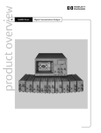
User's Guide
HP 83485A/B
Optical/Electrical
Plug-In Module
HP part number: 83485-90056
Printed in USA June 1999
Notice. The information contained in this document is subject to change
without notice. Hewlett-Packard makes no warranty of any kind with regard
to this material, including but not limited to, the implied warranties of
merchantability and tness for a particular purpose. Hewlett-Packard shall
not be liable for errors contained herein or for incidental or consequential
damages in connection with the furnishing, performance, or use of this
material.
Restricted Rights Legend. Use, duplication, or disclosure by the U.S.
Government is subject to restrictions as set forth in subparagraph (c) (1) (ii)
of the Rights in Technical Data and Computer Software clause at DFARS
252.227-7013 for DOD agencies, and subparagraphs (c) (1) and (c) (2) of the
Commercial Computer Software Restricted Rights clause at FAR 52.227-19 for
other agencies.
c Copyright Hewlett-Packard Company 1999
All Rights Reserved. Reproduction, adaptation, or translation without prior
written permission is prohibited, except as allowed under the copyright laws.
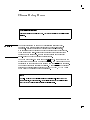
Safety Symbols
CAUTION
WARNING
The following safety symbols are used throughout this manual. Familiarize
yourself with each of the symbols and its meaning before operating this
instrument.
The caution sign denotes a hazard to the instrument. It calls attention to a
procedure which, if not correctly performed or adhered to, could result in
damage to or destruction of the instrument. Do not proceed beyond a caution
sign until the indicated conditions are fully understood and met.
The warning sign denotes a life-threatening hazard. It calls attention to a
procedure which, if not correctly performed or adhered to, could result
in injury or loss of life. Do not proceed beyond a warning sign until the
indicated conditions are fully understood and met.
L
Instruction
Manual
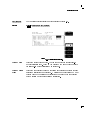
The instruction manual symbol. The product is marked with this symbol when it is necessary
for the user to refer to the instructions in the manual.
iii
General Safety Considerations
WARNING
Before this instrument is switched on, make sure it has been properly
grounded through the protective conductor of the ac power cable to a
socket outlet provided with protective earth contact.
Any interruption of the protective (grounding) conductor, inside or
outside the instrument, or disconnection of the protective earth terminal
can result in personal injury.
WARNING
There are many points in the instrument which can, if contacted, cause
personal injury. Be extremely careful.
Any adjustments or service procedures that require operation of the
instrument with protective covers removed should be performed only by
trained service personnel.
WARNING
If this instrument is not used as specied, the protection provided by the
equipment could be impaired. This instrument must be used in a normal
condition (in which all means for protection are intact) only.
CAUTION
Before this instrument is switched on, make sure its primary power circuitry
CAUTION
has been adapted to the voltage of the ac power source.
Failure to set the ac power input to the correct voltage could cause damage to
the instrument when the ac power cable is plugged in.
Electrostatic discharge (ESD) on or near input connectors can damage circuits
inside the instrument. Repair of damage due to misuse is not covered under
warranty.
Before connecting any cable to the electrical input, momentarily short the
center and outer conductors of the cable together. Personnel should be
properly grounded, and should touch the frame of the instrument before
touching any connector.
iv
Assistance
Product maintenance agreements and other customer assistance agreements
are available for Hewlett-Packard products.
For assistance, contact your nearest Hewlett-Packard Sales and Service Oce.
Hewlett-Packard Sales and Service Oces
U.S. FIELD OPERATIONS
Headquarters
California, Northern
California, Southern
Colorado
Georgia
Illinois
New Jersey
Texas
Hewlett-Packard Company
19320 Pruneridge Avenue
Cupertino, CA 95014 U.S.A.
(800) 752-0900
Hewlett-Packard Company
24 Inverness Place, East
Englewood, CO 80112
(303) 649-5000
Hewlett-Packard Company
150 Green Pond Road
Rockaway, NJ 07866
(201) 586-5400
Hewlett-Packard Company
301 East Evelyn
Mountain View, CA 94041
(415) 694-2000
Hewlett-Packard Company
2000 South Park Place
Atlanta, GA 30339
(404) 955-1500
Hewlett-Packard Company
1421 South Manhatten Ave.
Fullerton, CA 92631
(714) 999-6700
Hewlett-Packard Company
5201 Tollview Drive
Rolling Meadows, IL 60008
(708) 342-2000
Hewlett-Packard Company
930 East Campbell Road
Richardson, TX 75081
(214) 231-6101
EUROPEAN FIELD OPERATIONS
Headquarters
Hewlett-Packard S.A.
150, Route du Nant-d'Avril
1217 Meyrin 2/Geneva
Switzerland
(41 22) 780.8111
France
Hewlett-Packard France
1 Avenue Du Canada
Zone D'Activite De Courtaboeuf
F-91947 Les Ulis Cedex
France
(33 1) 69 82 60 60
Germany
Hewlett-Packard GmbH
Hewlett-Packard Strasse
61352 Bad Homburg
Germany
(+49 6172) 16-0
Great Britain
Hewlett-Packard Ltd.
Eskdale Road, Winnersh Triangle
Wokingham, Berkshire RG11 5DZ
v
Hewlett-Packard Sales and Service Oces (continued)
INTERCON FIELD OPERATIONS
Headquarters
Australia
Canada
China
Japan
Singapore
Hewlett-Packard Company
3495 Deer Creek Rd.
Palo Alto, California 94304-1316
(415) 857-5027
China Hewlett-Packard Company
38 Bei San Huan X1 Road
Shuang Yu Shu
Hai Dian District
Beijing, China
(86 1) 256-6888
Taiwan
Hewlett-Packard Taiwan
8th Floor, H-P Building
337 Fu Hsing North Road
Taipei, Taiwan
(886 2) 712-0404
vi
Hewlett-Packard Australia Ltd.
31-41 Joseph Street
Blackburn, Victoria 3130
(61 3) 895-2895
Yokogawa-Hewlett-Packard Ltd.
1-27-15 Yabe, Sagamihara
Kanagawa 229, Japan
(81 427) 59-1311
Hewlett-Packard Ltd.
17500 South Service Road
Trans-Canada Highway
Kirkland, Quebec H9J 2X8
Canada
(514) 697-4232
Hewlett-Packard Singapore Ltd.
Pte. Ltd.
Alexandra P.O. Box 87
singapore 9115
(65) 271-9444
Warranty
This Hewlett-Packard instrument product is warranted against defects in
material and workmanship for a period of one year from date of shipment.
During the warranty period, Hewlett-Packard Company will, at its option,
either repair or replace products which prove to be defective.
For warranty service or repair, this product must be returned to a service
facility designated by Hewlett-Packard. Buyer shall prepay shipping charges
to Hewlett-Packard and Hewlett-Packard shall pay shipping charges to return
the product to Buyer. However, Buyer shall pay all shipping charges, duties,
and taxes for products returned to Hewlett-Packard from another country.
Hewlett-Packard warrants that its software and rmware designated by
Hewlett-Packard for use with an instrument will execute its programming
instructions when properly installed on that instrument. Hewlett-Packard
does not warrant that the operation of the instrument, or software, or
rmware will be uninterrupted or error-free.
Limitation of Warranty
The foregoing warranty shall not apply to defects resulting from improper
or inadequate maintenance by Buyer, Buyer-supplied software or
interfacing, unauthorized modication or misuse, operation outside of the
environmental specications for the product, or improper site preparation
or maintenance.
NO OTHER WARRANTY IS EXPRESSED OR IMPLIED. HEWLETT-PACKARD
SPECIFICALLY DISCLAIMS THE IMPLIED WARRANTIES OF
MERCHANTABILITY AND FITNESS FOR A PARTICULAR PURPOSE.
Exclusive Remedies
THE REMEDIES PROVIDED HEREIN ARE BUYER'S SOLE AND EXCLUSIVE
REMEDIES. HEWLETT-PACKARD SHALL NOT BE LIABLE FOR ANY
DIRECT, INDIRECT, SPECIAL, INCIDENTAL, OR CONSEQUENTIAL
DAMAGES, WHETHER BASED ON CONTRACT, TORT, OR ANY OTHER
LEGAL THEORY.
vii
Contents
1. The Instrument at a Glance
Ordering information . . . . . . . . . . . . . .
Menu and Key Conventions . . . . . . . . . . . .
The HP 83485A/B Optical/Electrical Plug-In Module
Front panel of the plug-in module . . . . . . . .
Getting the best performance . . . . . . . . . .
Installing the plug-in module . . . . . . . . . .
Trigger . . . . . . . . . . . . . . . . . . . .
Cleaning Connections for Accurate Measurements . .
To clean a non-lensed connector . . . . . . . . .
To clean an adapter . . . . . . . . . . . . . .
To test insertion loss . . . . . . . . . . . . . .
To test return loss . . . . . . . . . . . . . . .
2. Channel Setup Menu
.
.
.
.
.
.
.
.
.
.
.
.
.
.
.
.
.
.
.
.
.
.
.
.
1-4
1-6
1-8
1-10
1-11
1-11
1-12
1-13
1-15
1-16
1-16
1-17
.
.
.
.
.
.
.
.
.
.
.
.
.
.
.
.
.
.
.
.
.
.
.
.
.
.
.
.
.
.
.
.
.
.
.
.
.
.
.
.
.
.
.
.
.
.
.
.
.
.
.
.
.
.
.
.
.
.
.
.
.
.
.
.
2-4
2-5
2-6
2-7
2-7
2-9
2-9
2-11
Factory Calibrations . . . . . . . . . .
Mainframe Calibration . . . . . . . .
O/E Factory Wavelength Calibration .
User Calibrations|Optical and Electrical
O/E User-Wavelength Calibration . . .
Plug-in Module Vertical Calibration . .
Oset Zero Calibration . . . . . . . .
Dark Calibration . . . . . . . . . .
Channel Skew Calibration . . . . . .
.
.
.
.
.
.
.
.
.
.
.
.
.
.
.
.
.
.
.
.
.
.
.
.
.
.
.
.
.
.
.
.
.
.
.
.
.
.
.
.
.
.
.
.
.
.
.
.
.
.
.
.
.
.
.
.
.
.
.
.
.
.
.
3-4
3-4
3-6
3-7
3-9
3-11
3-12
3-14
3-15
Displaying the Channel Setup menus
Display . . . . . . . . . . . .
Scale . . . . . . . . . . . . .
Offset . . . . . . . . . . . .
Bandwidth/Wavelength. . . . .
Channel autoscale . . . . . .
External scale . . . . . . . .
Calibrate . . . . . . . . . . .
NNNNNNNNNNNNNNNNNNNNNNN
NNNNNNNNNNNNNNNNN
NNNNNNNNNNNNNNNNNNNN
NNNNNNNNNNNNNNNNNNNNNNNNNNNNNNNNNNNNNNNNNNNNNNNNNNNNNNNNNNNNNNNNNNNNNNNNNNNNN
NNNNNNNNNNNNNNNNNNNNNNNNNNNNNNNNNNNNNNNNNNNNNNNNNNNNN
NNNNNNNNNNNNNNNNNNNNNNNNNNNNNNNNNNNNNNNNNNNNNNNNNNNNNNNNNNNNNN
NNNNNNNNNNNNNNNNNNNNNNNNNNNNN
3. Calibration Overview
.
.
.
.
.
.
.
.
Contents-1
Probe Calibration . . . . . . . . . . . . . . . . .
External Scale . . . . . . . . . . . . . . . . . . . .
Complete Calibration Summary . . . . . . . . . . . .
4. Specications and Regulatory Information
3-16
3-18
3-20
.
.
.
.
.
.
4-3
4-3
4-9
4-10
4-10
4-11
If the mainframe does not operate . . . . . . . . . . .
If the plug-in does not operate . . . . . . . . . . . .
Error Messages . . . . . . . . . . . . . . . . . . .
5-3
5-4
5-6
Specications . . . . . . . .
Vertical specications . . .
Environmental specications
Characteristics . . . . . . .
Trigger input characteristics
Declaration of Conformity . .
5. In Case of Diculty
Index
Contents-2
.
.
.
.
.
.
.
.
.
.
.
.
.
.
.
.
.
.
.
.
.
.
.
.
.
.
.
.
.
.
.
.
.
.
.
.
.
.
.
.
.
.
.
.
.
.
.
.
.
.
.
.
.
.
.
.
.
.
.
.
.
.
.
.
.
.
Figures
1-1.
2-1.
2-2.
2-3.
3-1.
3-2.
3-3.
3-4.
3-5.
3-6.
Front panel of the plug-in module.
Optical Channel Setup menu. . . .
Electrical Channel Setup menu. . .
A typical Cal Status display. . . .
Current Frame 1Temp condition .
Plug-in calibration menu . . . . .
Oset Zero Calibration . . . . . .
Dark calibration menu . . . . . .
Electrical Channel Calibrate Menu .
External Scale Menu . . . . . . .
.
.
.
.
.
.
.
.
.
.
.
.
.
.
.
.
.
.
.
.
.
.
.
.
.
.
.
.
.
.
.
.
.
.
.
.
.
.
.
.
.
.
.
.
.
.
.
.
.
.
.
.
.
.
.
.
.
.
.
.
.
.
.
.
.
.
.
.
.
.
.
.
.
.
.
.
.
.
.
.
.
.
.
.
.
.
.
.
.
.
.
.
.
.
.
.
.
.
.
.
.
.
.
.
.
.
.
.
.
.
.
.
.
.
.
.
.
.
.
.
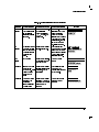
Factory Calibration Summary . . . . . . . . . . . . .
Optical and Electrical Channel User Calibration Summary
Miscellaneous User Calibration Summary . . . . . . . .
Complete Calibration Summary . . . . . . . . . . . .
.
.
.
.
. 3-4
. 3-8
. 3-9
. 3-20
1-10
2-3
2-4
2-13
3-5
3-10
3-13
3-15
3-17
3-19
Tables
3-1.
3-2.
3-3.
3-4.
Contents-3
Contents
1
The Instrument at a
Glance
The Instrument at a Glance
What you'll nd in this chapter
This chapter describes:
options and accessories
the key conventions used in this manual
the front panel, rear panel and keys that do
not
display menus on the screen
lightwave connector care
Understanding the information in this chapter will help you successfully operate the instrument.
CAUTION
The input circuits can be damaged by electrostatic discharge (ESD).
Therefore, avoid applying static discharges to the front-panel input
connectors. Before connecting any coaxial cable to the connectors,
momentarily short the center and outer conductors of the cable together.
Avoid touching the front-panel input connectors without rst touching
the frame of the instrument. Be sure that the instrument is properly
earth-grounded to prevent buildup of static charge.
The HP 83485A optical/electrical plug-in module incorporates two
measurement channels, one optical and one electrical. Each channel has two
selectable bandwidth settings. In the lower bandwidth modes of 12.4 GHz,
oscilloscope noise performance is excellent, while the 20 GHz mode allows
greater delity for high speed signals.
The HP 83485B optical/electrical plug-in module incorporates a 30 GHz
optical measurement channel and a 40 GHz electrical channel. The electrical
channel also has a reduced-bandwidth setting of 18 GHz for improved noise
performance.
The integrated optical channel reduces mismatch loss variation by eliminating
signal distorting cables and connectors associated with the use of external
receivers in order to accurately characterize optical waveforms. The optical
1-2
The Instrument at a Glance
channel is calibrated at 1310 nm and 1550 nm to provide both accurate
display of the received optical waveform in optical power units and
measurement of the signal's average power. In addition, the User Cal feature
provides for consistent accuracy at any wavelength between 1200 nm and
1600 nm using a source and power meter.
The HP 83485A optical/electrical plug-in module also is a calibrated
SONET/SDH reference receiver that is measured to comply to ITU-TS
(formerly CCITT) G.957 and Bellcore GR-253-CORE frequency response
requirements for transmitter compliance testing. By either pressing
a front-panel button or issuing an HP-IB command, a fourth-order
Bessel-Thomson lter is inserted into or removed from the measurement
channel by a very repeatable HP microwave switch. The switch removes the
potential variability and the time wasted by manually inserting and removing
the lter when alternating between high-delity waveform characterization
and SONET/SDH compliance testing.
The HP 83485B optical/electrical plug-in module includes a reference receiver
path, similar to the HP 83485A, for 10 Gb/s transmitter test. Although
no industry standards exist for 10 Gb/s testing, the HP 83485B has been
designed to meet anticipated future standards.
The electrical measurement channel may be used to perform measurements
on tributary electrical signals, to evaluate receiver performance in transceiver
testing, for measurements with HP's wide range of external optical receivers,
or for general purpose measurements.
The HP 83485A optical/electrical plug-in module provides:
12.4 GHz and 20 GHz optical channel
12.4 GHz and 20 GHz electrical channel
Switchable SDH/SONET lter for transceiver compliance testing
Trigger channel input to the mainframe
The HP 83485B optical/electrical plug-in module provides:
30 GHz optical channel
18 GHz and 40 GHz electrical channel
Switchable SDH/SONET lter for transceiver performance testing
Trigger channel input to the mainframe
1-3
Ordering information
HP 83485A options
Option 030 Built-in STM-1/OC-3 155 Mb/s SDH/SONET reference receiver
Option 032 Built-in STM-4/OC-12 622 Mb/s SDH/SONET reference receiver
Option 034 Built-in STM-16/OC-48 2.488 Gb/s SDH/SONET reference
receiver
Option 0BW HP 83485A/B Service Guide
Option 0B1 Additional set of user documentation
Option 0B0 Deletes the user documentation
Option UK6 Measured performance data
HP 83485B options
Option 001 Latest operating system rmware for the HP 83480A mainframe
Option 002 Latest operating system rmware for the HP 54750A mainframe
Option 040 Fourth order lter/10 Gb/s reference receiver
Option 050 Fifth order lter/10 Gb/s reference receiver
Optical connector
interface options
Option 011 Diamond HMS-10/HP
Option 012 FC/PC
Option 013 DIN 47256
Option 014 ST
Option 015 Biconic
Option 017 SC
1-4
The Instrument at a Glance
Ordering information
Optional accessories
HP 54006A 6 GHz divider probe
HP 54008A 22 ns delay line
HP 54118A 500 MHz to 18 GHz trigger
HP 10086A ECL terminator
SMA (f-f) adapter, HP part number 1250-1158
SMA 50
termination, HP part number 1810-0118, 1 each
APC 3.5 (f-f) adapter, HP part number 1250-1749
APC 2.4 (f-f) adapter, HP 11900B
APC 2.4 to 3.5 (f-f) adapter, HP 11901B
HP 81000AI Diamond HMS-10/HP connector interface
HP 81000FI FC/PC/SPC/APC connector interface
HP 81000KI SC connector interface
HP 81000SI DIN 47256/4108.6 connector interface
HP 81000VI ST connector interface
HP 81000WI Biconic
1-5
Menu and Key Conventions
The keys labeled Trigger, Disk, and Run are all examples of front-panel keys.
Pressing some front-panel keys accesses menus of functions that are displayed
along the right side of the display screen. These menus are called softkey
menus.
Softkey menus list functions other than those accessed directly by the
front-panel keys. To activate a function on the softkey menu, press the
unlabeled key immediately next to the annotation on the screen. The
unlabeled keys next to the annotation on the display are called softkeys.
Additional functions are listed in blue type above and below some of the
front-panel keys. These functions are called shifted functions. To activate a
shifted function, press the blue front-panel Shift key and the front-panel key
next to the desired function.
Throughout this manual front-panel keys are indicated by a box around the
key label, for example, 4Timebase5. Softkeys are indicated by shading on the
key label, for example, Mask Align . The softkeys displayed depend on
the front-panel key pressed and which menu is selected. Shifted functions
are indicated by the front-panel 4Shift5 key followed by the shaded shifted
function, for example the Local function (above the 4Stop/Single5 front-panel
key) will be shown as 4Shift5, 4Local5.
A softkey with On and O in its label can be used to turn the softkey's
function on or o. To turn the function on, press the softkey so On is
highlighted. To turn the function o, press the softkey so O is highlighted.
An On or O softkey function will be indicated throughout this manual as:
Test On.
NNNNNNNNNNNNNNNNNNNNNNNNNNNNNNNN
NNNNNNNNNNNNNN
A softkey such as Sweep Triggered Freerun oers you a choice of
functions. In this case you could choose Triggered by pressing the softkey
until Triggered is highlighted, or choose Freerun by pressing the softkey until
Freerun is highlighted. A choices softkey will be indicated throughout this
manual as: Sweep Triggered Freerun Triggered.
NNNNNNNNNNNNNNNNNNNNNNNNNNNNNNNNNNNNNNNNNNNNNNNNNNNNNNNNNNNNNNNNNNNNNNN
NNNNNNNNNNNNNNNNNNNNNNNNNNNNNNNNNNNNNNNNNNNNNNNNNNNNNNNNNNNNNNNNNNNNNNN
When some softkeys, such as Calibrate probe , are pressed the rst time,
a measurement will be made and the result will be provided. Some softkeys,
such as Offset require the entry of a numeric value. To enter or change the
NNNNNNNNNNNNNNNNNNNNNNNNNNNNNNNNNNNNNNNNNNNNNNN
NNNNNNNNNNNNNNNNNNNN
1-6
The Instrument at a Glance
Menu and Key Conventions
value, use the general purpose knob located below the front-panel Measure
section.
1-7
The HP 83485A/B Optical/Electrical Plug-In Module
The HP 83485A/B optical/electrical plug-in modules are two of several plug-in
modules available for the HP 83480A, 54750A mainframes. Their main
features are:
Integrated, calibrated optical channel.
Optical channel includes switchable SONET/SDH lter.
Electrical measurement channel.
2.5 GHz trigger channel.
Both optical and electrical measurement channels have user selectable
bandwidths of 12.4 or 20 GHz. (HP 83485A only)
30 GHz optical channel bandwidth and user selectable 18 or 40 GHz
electrical channel bandwidth. (HP 83485B only)
3.5 mm (m) connectors on electrical measurement channel and trigger
channel. (2.4 mm (m) connector on electrical channel of HP 83485B.)
One probe power connector.
One auxiliary power connector.
Optical channel has an HP universal adapter for 9/125 m single-mode ber
input.
NOTE
If you wish to use the HP 83485A/B optical plug-in module in an HP 54750A digitizing oscilloscope,
a rmware upgrade must rst be installed. Order the HP 83480K communications rmware kit and
follow the installation instructions.
1-8
The Instrument at a Glance
The HP 83485A/B Optical/Electrical Plug-In Module
The purpose of the plug-in module is to provide measurement channels,
including sampling, for the mainframe. The plug-in module scales the input
signal, sets the bandwidth of the system, and allows the oset to be adjusted
so the signal can be viewed. The output of the plug-in module is an analog
signal that is applied to the ADCs on the acquisition boards inside the
mainframe. The plug-in module also provides a trigger signal input to the
time base/trigger board inside the mainframe.
1-9
The Instrument at a Glance
The HP 83485A/B Optical/Electrical Plug-In Module
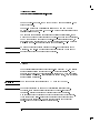
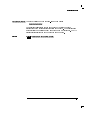
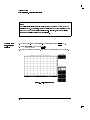
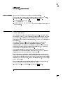
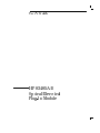
Front panel of the plug-in module
The plug-in module takes up two of the four mainframe slots. The optical
channel provides calibrated measurement of optical waveforms in power
units. Bandwidths are selectable on both channels to optimize sensitivity and
bandwidth. The front panel of the plug-in module has two channel inputs
and an external trigger input. The front panel also has two Probe Power
connectors for HP 54700-series probes, Aux Power connector for general
purpose use, and a key for each channel that displays the softkey menu. The
softkey menu allows you to access the channel setup features of the plug-in
module.
The front-panel Probe Power connectors allow automatic channel scaling and
probe calibration with HP 54700 series probes. The front-panel Aux Power
connector provides only power to HP 54700 series probes for use as a trigger
input. Probe calibration and scaling are not required for a trigger input.
Figure 1-1. Front panel of the plug-in module.
1-10
The Instrument at a Glance
The HP 83485A/B Optical/Electrical Plug-In Module
Getting the best performance
To ensure you obtain the specied accuracy, you must perform a plug-in
module vertical calibration. The calibration must also be performed when you
move a plug-in module from one slot to another, or from one mainframe to
another. Refer to Chapter 3 for information on performing a plug-in module
vertical calibration.
Installing the plug-in module
You do not need to turn o the mainframe to install or remove the plug-in
modules.
NOTE
If you wish to use the HP 83485A/B optical plug-in module in an HP 54750A digitizing oscilloscope,
a rmware upgrade must rst be installed. Order the HP 83480K communications rmware kit and
follow the installation instructions.
1-11
The Instrument at a Glance
The HP 83485A/B Optical/Electrical Plug-In Module
To use the plug-in module, the HP 83480A/54750A rmware revision 3.0 or
higher is required.
The plug-in module can be installed in slots 1 and 2 or 3 and 4 on the
HP 83480A, 54750A mainframe. The plug-in module will not function if it is
installed in slots 2 and 3.
To make sure the analyzer meets all of the published specications, there
must be a good ground connection from the plug-in module to the mainframe.
The RF connectors on the rear of the plug-in module are spring loaded, so
nger-tighten the knurled screw on the front panel of the plug-in module to
make sure the plug-in is securely seated in the mainframe.
CAUTION
Do not use extender cables to operate the plug-in module outside of the
mainframe. The plug-in module using extender cables can be damaged by
improper grounding when using extender cables.
Trigger
The external trigger level range for this plug-in module is 61 V. The trigger
source selection follows the slots the plug-in module is installed in. For
example, if the plug-in module is installed in slots 1 and 2, then the trigger
source is listed as trigger 2. If it is installed in slots 3 and 4, then the trigger
source is listed as trigger 4.
CAUTION
The maximum safe input voltage is 62 V + peak ac (+16 dBm).
CAUTION
The input circuits can be damaged by electrostatic discharge (ESD).
Therefore, avoid applying static discharges to the front-panel input
connectors. Before connecting any coaxial cable to the connectors,
momentarily short the center and outer conductors of the cable together.
Avoid touching the front-panel input connectors without rst touching
the frame of the instrument. Be sure that the instrument is properly
earth-grounded to prevent buildup of static charge.
1-12
Cleaning Connections for Accurate Measurements
CAUTION
Accurate and repeatable measurements require clean connections. Use the
following guidelines to achieve the best possible performance when making
measurements on a ber-optic system:
Keep connectors covered when not in use.
Use dry connections whenever possible.
Use the cleaning methods described in this section.
Use care in handling all ber-optic connectors.
When inserting a ber-optic connector into a front-panel adapter, make
sure that the ber end does not touch the outside of the mating connector
or adapter.
Because of the small size of cores used in optical bers, care must be used to
ensure good connections. Poor connections result from core misalignment, air
gaps, damaged ber ends, contamination, and improper use and removal of
index-matching compounds.
Use dry connections. Dry connectors are easier to clean and to keep clean.
Dry connections can be used with physically contacting connectors (for
example, Diamond HMS-10/HP, FC/PC, DIN, and ST). If a dry connection
has 40 dB return loss or better, making a wet connection will probably not
improve (and can degrade) performance.
Hewlett-Packard strongly recommends that index matching compounds NOT
be applied to their instruments and accessories. Some compounds, such as
gels, may be dicult to remove and can contain damaging particulates. If
you think the use of such compounds is necessary, refer to the compound
manufacturer for information on application and cleaning procedures.
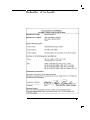
Cleaning Accessories
Item
Isopropyl alcohol
Cotton swabs
Small foam swabs
Compressed dust remover (non-residue)
HP Part Number
8500-5344
8520-0023
9300-1223
8500-5262
1-13
The Instrument at a Glance
Cleaning Connections for Accurate Measurements
Dust Caps Provided with Lightwave Instruments
Item
Laser shutter cap
FC/PC dust cap
Biconic dust cap
DIN dust cap
HMS10/HP dust cap
ST dust cap
HP Part Number
08145-64521
08154-44102
08154-44105
5040-9364
5040-9361
5040-9366
Inspecting Fiber-Optic Consistent measurements with your lightwave equipment are a good
indication that you have good connections. However, you may wish to know
Cables
the insertion loss and/or return loss of your lightwave cables or accessories. If
you test your cables and accessories for insertion loss and return loss upon
receipt, and retain the measured data for comparison, you will be able to tell
in the future if any degradation has occurred.
Connector (or insertion) loss is one important performance characteristic of a
lightwave connector. Typical values are less than 1 dB of loss, and sometimes
as little as 0.1 dB of loss with high performance connectors. Return loss
is another important factor. It is a measure of reection: the less reection
the better (the larger the return loss, the smaller the reection). The best
physically contacting connectors have return losses better than 50 dB,
although 30 to 40 dB is more common.
You can visually inspect your cables
Although it is not necessary, visual inspection of ber ends can be helpful. Contamination or
imperfections on the cable end face can be detected as well as cracks or chips in the ber itself. Use
a microscope (100X to 200X magnication) to inspect the entire end face for contamination, raised
metal, or dents in the metal as well as any other imperfections. Inspect the ber for cracks and chips.
Visible imperfections not touching the ber core may not aect performance (unless the imperfections
keep the bers from contacting).
1-14
The Instrument at a Glance
Cleaning Connections for Accurate Measurements
To clean a non-lensed connector
CAUTION
Do not use any type of foam swab to clean optical ber ends. Foam swabs
can leave lmy deposits on ber ends that can degrade performance.
1. Apply isopropyl alcohol to a clean lint-free cotton swab or lens paper.
Cotton swabs can be used as long as no cotton bers remain on the ber
end after cleaning.
2. Before cleaning the ber end, clean the ferrules and other parts of the
connector.
3. Apply isopropyl alcohol to a new clean lint-free cotton swab or lens paper.
4. Clean the ber end with the swab or lens paper. Move the swab or lens
paper back and forth across the ber end several times.
Some amount of wiping or mild scrubbing of the ber end can help
remove particles when application of alcohol alone will not remove
them. This technique can remove or displace particles smaller than one
micron.
5. Immediately dry the ber end with a clean, dry, lint-free cotton swab or
lens paper.
6. Blow across the connector end face from a distance of 6 to 8 inches using
ltered, dry, compressed air. Aim the compressed gas at a shallow angle to
the ber end face.
Nitrogen gas or compressed dust remover can also be used.
CAUTION
Do not shake, tip, or invert compressed air canisters, because this releases
particles in the can into the air. Refer to instructions provided on the
compressed air canister.
7. As soon as the connector is dry, connect or cover it for later use.
1-15
The Instrument at a Glance
Cleaning Connections for Accurate Measurements
To clean an adapter
1. Apply isopropyl alcohol to a clean foam swab.
Cotton swabs can be used as long as no cotton bers remain after
cleaning. The foam swabs listed in this section's introduction are small
enough to t into adapters.
Although foam swabs can leave lmy deposits, these deposits are very
thin, and the risk of other contamination buildup on the inside of
adapters greatly outweighs the risk of contamination by foam swabs.
2. Clean the adapter with the foam swab.
3. Dry the inside of the adapter with a clean, dry, foam swab.
4. Blow through the adapter using ltered, dry, compressed air.
Nitrogen gas or compressed dust remover can also be used.
CAUTION
Do not shake, tip, or invert compressed air canisters, because this releases
particles in the can into the air. Refer to instructions provided on the
compressed air canister.
To test insertion loss
Use an appropriate lightwave source and a compatible lightwave receiver to
test insertion loss. Examples of test equipment congurations include the
following equipment:
HP 71450A or 71451A optical spectrum analyzers with Option 002 built-in
white light source
HP 8702 or 8703 lightwave component analyzer system
HP 83420 lightwave test set with an HP 8510 network analyzer
HP 8153 lightwave multimeter with a source and power sensor module
1-16
The Instrument at a Glance
To test return loss
Use an appropriate lightwave source, a lightwave receiver, and lightwave
coupler to test return loss. Examples of test equipment congurations include
the following equipment:
HP 8703 lightwave component analyzer
HP 8702 analyzer with the appropriate source, receiver, and lightwave
coupler
HP 8504 precision reectometer
HP 8153 lightwave multimeter with a source and power sensor module in
conjunction with a lightwave coupler
HP 81554SM dual source and HP 81534A return loss module
1-17
The Instrument at a Glance
2
Channel Setup Menu
Channel Setup Menu
What you'll nd in this chapter
This chapter describes the Channel Setup menu. A key tree and description of the available functions
is included.
CAUTION
The input circuits can be damaged by electrostatic discharge (ESD).
Therefore, avoid applying static discharges to the front-panel input
connectors. Before connecting any coaxial cable to the connectors,
momentarily short the center and outer conductors of the cable together.
Avoid touching the front-panel input connectors without rst touching
the frame of the instrument. Be sure that the instrument is properly
earth-grounded to prevent buildup of static charge.
At the top of the plug-in module are the 4Channel5 keys. These keys give you
access to the Channel Setup menu for each input. The Channel Setup menu
is displayed on the right side of the screen when the 4Channel5 key is pressed.
There are several types of softkeys available. A description of the dierent
softkeys and their functions is provided in the HP 83480A, 54750A User's
Quick Start Guide supplied with the mainframe.
NOTE
The plug-in module has both an electrical channel and an optical channel. Although many of the
softkeys are similar, some dierences exist. The examples in this book use the optical channel and
note when the user would see dierences if using the electrical channel.
2-2
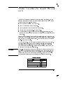
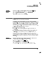
Channel Setup Menu
Figure 2-1. Optical Channel Setup menu.
2-3
Channel Setup Menu
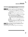
Figure 2-2. Electrical Channel Setup menu.
Displaying the Channel Setup menus
To display the optical Channel Setup menu, press the optical 4Channel5 key.
2-4
Channel Setup Menu
To display the electrical Channel Setup menu, press the electrical 4Channel5
key.
Display
aaaaaaaaaaaaaaaaaaaaaaaaaaaaaaaaaaaa
The Display function turns the channel display o and on. When the channel
display is on, a waveform is displayed for that channel, unless the oset is
adjusted so the waveform is clipped o of the display.
The channel number, vertical scaling, and oset are displayed at the bottom
left of the waveform area. They remain on the display until the channel
is turned o, or an automatic measurement is performed. The automatic
measurement results share the same area of the display as the channel
setups.
When the channel display is o, the waveform display for that channel is
turned o, pulse parameter measurements are stopped and acquisition on
that channel is stopped, unless it is needed as an operand for waveform math
functions.
Even though the channel display is o, you can still use the plug-in as a
trigger source or as a function source in the Math menu. However, the
analyzer will not trigger unless one or more of the other channel displays are
turned on, or unless a math function is using one of the channels.
Key Path
4Channel5
NNNNNNNNNNNNNNNNNNNNNNN
Display
2-5
Channel Setup Menu
Scale
aaaaaaaaaaaaaaaaaaaaaaaaaa
The Scale softkey controls the vertical scaling of the waveform. If the ne
mode is o, then the knob and arrow keys change the vertical scaling in a
1-2-5 sequence. When ne mode is on, the knob and arrow keys change the
vertical scaling in 1 mV increments. You can also use the keypad to enter
values in 1 mV increments, independent of the ne mode selection.
The units the scale is displayed in depend on the unit of measure selected
with the Units softkey. The choices for units are volts or watts. (Amperes, or
unknown are available on electrical channels only.)
Key Path
4Channel5
2-6
NNNNNNNNNNNNNNNNN
Scale
Channel Setup Menu
Offset
aaaaaaaaaaaaaaaaaaaaaaaaaaaaaaa
The Oset softkey moves the waveform vertically. It is similar to the position
control on analog oscilloscopes. The advantage of digital oset is that it is
calibrated. The oset voltage for electrical channels is the voltage at the
center of the graticule area, and the range of oset is 612 times the full
resolution channel scale. For optical channels, the oset wattage is the
wattage two graticule divisions above the bottom of the screen. This is set
because, unlike voltage displays, \negative" power levels do not exist but the
zero power level can be viewed clearly when the oset is set to zero watts.
You can use the knob, arrow keys, or keypad to change the oset setting. The
ne mode also works with oset.
When an HP 54700-series active probe is used with the plug-in module and
is connected to the probe power connector adjacent to the channel input,
the oset control adjusts the external scale factor and oset of the hybrid
inside the active probe. A probe connected to the auxiliary power connector
adjacent to the trigger input will function, but the channel scale factor will
not be adjusted automatically.
The optical channel displays the value in watts and the electrical channel
displays the value in volts.
Key Path
4Channel5
NNNNNNNNNNNNNNNNNNNN
Offset
Bandwidth/Wavelength. . .
aaaaaaaaaaaaaaaaaaaaaaaaaaaaaaaaaaaaaaaaaaaaaaaaaaaaaaaaaaaaaaaaaaaaaaaaaaaaaaaaaaaaaaaaaaaaaaaaaaaaaaaaaaaaaaaaaaaaaaaaa
You can use the Bandwidth/Wavelength. . . softkey to change the
bandwidth and wavelength settings and turn the lter on and o on the
optical channel.
NNNNNNNNNNNNNNNNNNNNNNNNNNNNNNNNNNNNNNNNNNNNNNNNNNNNNNNNNNNNNNNNNNNNNNNNNNNNN
2-7
Channel Setup Menu
NNNNNNNNNNNNNNNNNNNNNNNNNNNNN
Bandwidth
HP 83485A: This function is available on the electrical channel and on the
optical channel only when the lter is switched o.
You can use the Bandwidth function to select either the 12.4 GHz or the
20 GHz bandwidth.
HP 83485B: This function is available on the electrical channel only.
You can use the Bandwidth function to select either the 18 GHz or 40 GHz
bandwidth.
Key Path
NNNNNNNNNNNNNNNNNNNNNNNNNNNNNNNNNNNNNNNNN
Filter On Off
4Channel5
NNNNNNNNNNNNNNNNNNNNNNNNNNNNNNNNNNNNNNNNNNNNNNNNNNNNNNNNNNNNNNNNNNNNNNNNNNNNN NNNNNNNNNNNNNNNNNNNNNNNNNNNNN
Bandwidth/Wavelength. . . Bandwidth
The Filter function allows a SONET/SDH Bessel-Thomson lter to be switched
into the channel to create a SONET/SDH reference receiver.
HP 83485A: Option 030 is 155 Mb/s STM-1/OC-3. Option 32 is 622 Mb/s
STM-4/OC-12. Option 34 is 2.488 Gb/s STM-16/OC-48.
HP 83485B: Option 40 is 10 Gb/s fourth-order lter. Option 050 is 10 Gb/s
fth-order lter.
Key Path
NNNNNNNNNNNNNNNNNNNNNNNNNNNNNNNN
Wavelength
4Channel5
NNNNNNNNNNNNNNNNNNNNNNNNNNNNNNNNNNNNNNNNNNNNNNNNNNNNNNNNNNNNNNNNNNNNNNNNNNNNN NNNNNNNNNNNNNNNNNNNNNNNNNNNNNNNNNNNNNNNNN
Bandwidth/Wavelength. . . Filter On Off
This function is only available on the optical channel.
The Wavelength function selects the desired wavelength for calibrated
measurements. Factory calibrated wavelengths are 1310 nm and 1550 nm. A
user-calibrated wavelength is also available and can be calibrated in the range
from 1000 nm to 1600 nm. Refer to Chapter 3 for additional information on
performing a calibration.
Key Path
4Channel5
2-8
NNNNNNNNNNNNNNNNNNNNNNNNNNNNNNNNNNNNNNNNNNNNNNNNNNNNNNNNNNNNNNNNNNNNNNNNNNNNN NNNNNNNNNNNNNNNNNNNNNNNNNNNNNNNN
Bandwidth/Wavelength. . . Wavelength
Channel Setup Menu
Channel autoscale
aaaaaaaaaaaaaaaaaaaaaaaaaaaaaaaaaaaaaaaaaaaaaaaaaaaaaaaaaaaaaaaaaaaaaaaaaaaaaaaaaaa
The Channel Autoscale function provides a convenient and fast method for
determining the standard vertical scale setting with the highest resolution
that will not clip the waveform. Timebase and trigger settings are not
aected.
This function is useful in manufacturing environments where the timebase
and trigger settings remain constant and only the vertical scale needs to be
adjusted for signal level variations in multiple DUTs.
Key Path
4Channel5
NNNNNNNNNNNNNNNNNNNNNNNNNNNNNNNNNNNNNNNNNNNNNNNNNNNNN
Channel autoscale
External scale . . .
aaaaaaaaaaaaaaaaaaaaaaaaaaaaaaaaaaaaaaaaaaaaaaaaaaaaaaaaaaaaaaaaaaaaaaaaaaaaaaaaaaaaaaaaaaaaaaaaa
The External Scale function allows you to setup the analyzer to use external
optical-to-electrical converters or attenuators. Scaling is automatically
adjusted to account for the external device.
Key Path
NNNNNNNNNNNNNNNNNNNNNNNNNNNNNNNNNNN
Atten units
4Channel5
NNNNNNNNNNNNNNNNNNNNNNNNNNNNNNNNNNNNNNNNNNNNNNNNNNNNNNNNNNNNNN
External scale . . .
The Atten Units function lets you select how you want the probe attenuation
factor represented. The choices are either decibel or ratio. The formula for
calculating decibels is:
20 log Vout or 10 log Pout
Vin
Pin
2-9
Channel Setup Menu
NNNNNNNNNNNNNNNNNNNNNNNNNNNNNNNNNNN
Attenuation
The Attenuation function lets you select an attenuation that matches the
device connected to the analyzer. When the attenuation is set correctly, the
analyzer maintains the current scale factors if possible. All marker values and
voltage or wattage measurements will reect the actual signal at the input to
the external device.
The attenuation range is from 0.0001:1 to 1,000,000:1. When you connect
a compatible active probe to the probe power connector, adjacent to the
channel input, the instrument automatically sets the attenuation. For all
other devices, set the probe attenuation with the knob, arrow keys, or
keypad.
NOTE
Refer to Chapter 3 for information on calibrating to the tip of the probe.
Key Path
NNNNNNNNNNNNNNNNN
Units
Key Path
4Channel5
NNNNNNNNNNNNNNNNNNNNNNNNNNNNNNNNNNNNNNNNNNNNNNNNNNNNNNNNNNNNNN NNNNNNNNNNNNNNNNNNNNNNNNNNNNNNNNNNN
External scale . . . Attenuation
The Units function lets you select the unit of measure appended to the
channel scale, oset, trigger level, and vertical measurement values. For the
optical channel these units are Volts or Watts. For the electrical channel the
units are Volts, Amperes, Watts, or unknown. Use Volt for voltage probes,
Ampere for current probes, Watt for optical-to-electrical (O/E) converters, and
unknown when there is no unit of measure or when the unit of measure is
not one of the available choices.
4Channel5
2-10
NNNNNNNNNNNNNNNNNNNNNNNNNNNNNNNNNNNNNNNNNNNNNNNNNNNNNNNNNNNNNN NNNNNNNNNNNNNNNNN
External scale . . . Units
Channel Setup Menu
Ext gain and
Ext offset
NNNNNNNNNNNNNNNNNNNNNNNNNN
NNNNNNNNNNNNNNNNNNNNNNNNNNNNNNNN
Key Path
When you select Ampere, Watt, or unknown on an electrical channel or
Voltage on an optical channel, two additional functions become available:
External Gain and External Oset. These two additional functions allow
you to compensate for the actual characteristics of the probe rather than its
ideal characteristics. For example, you might have an amplied lightwave
converter with ideal characteristics of 300 V/W with 0 V oset. But, its actual
characteristics are 324 V/W with 1 mV of output oset. Therefore, set the
External Gain to 324 V/W and the External Oset to 1 mV.
External scale . . . Units Volt Ext gain or
Ext Offset
4Channel5
NNNNNNNNNNNNNNNNNNNNNNNNNNNNNNNNNNNNNNNNNNNNNNNNNNNNNNNNNNNNNN NNNNNNNNNNNNNNNNN NNNNNNNNNNNNNN NNNNNNNNNNNNNNNNNNNNNNNNNN
NNNNNNNNNNNNNNNNNNNNNNNNNNNNNNNN
External scale . . . Units Watt Ext gain or
Ext Offset
4Channel5
NNNNNNNNNNNNNNNNNNNNNNNNNNNNNNNNNNNNNNNNNNNNNNNNNNNNNNNNNNNNNN NNNNNNNNNNNNNNNNN NNNNNNNNNNNNNN NNNNNNNNNNNNNNNNNNNNNNNNNN
NNNNNNNNNNNNNNNNNNNNNNNNNNNNNNNN
External scale . . . Units Unknown Ext gain or
Ext Offset
4Channel5
NNNNNNNNNNNNNNNNNNNNNNNNNNNNNNNNNNNNNNNNNNNNNNNNNNNNNNNNNNNNNN NNNNNNNNNNNNNNNNN NNNNNNNNNNNNNNNNNNNNNNN NNNNNNNNNNNNNNNNNNNNNNNNNN
NNNNNNNNNNNNNNNNNNNNNNNNNNNNNNNN
Calibrate
aaaaaaaaaaaaaaaaaaaaaaaaaaaaaaaaaaaaaaaaaaaaa
The calibrate menu allows you to null out any skew between probes or
cables, remove the eects of osets in the internal O/E converter, recalibrate
the responsivity of the O/E converter, and check the present calibration status
of the analyzer.
Key Path
4Channel5
NNNNNNNNNNNNNNNNNNNNNNNNNNNNN
Calibrate
2-11
Channel Setup Menu
NNNNNNNNNNNNNN
Skew
The Skew function changes the horizontal position of a waveform on the
display. The Skew function has a range of +100 s. You can use skew to
compensate for dierences in cable or probe lengths. It also allows you to
place the triggered edge at the center of the display when you are using a
power splitter connected between the channel and trigger inputs. Another
use for skew is when you are comparing two waveforms that have a timing
dierence between them. If you are more interested in comparing the shapes
of two waveforms rather than the actual timing dierence between them, you
can use Skew to overlay one waveform on top of the other waveform.
To skew two channels
1. Turn both channels on and overlay the signals vertically.
2. Expand the time base so the rising edges are about a 45 degree angle.
3. Adjust the skew on one of channels so that the rising edges overlap at the 50 percent points.
Key Path
4Channel5
2-12
NNNNNNNNNNNNNNNNNNNNNNNNNNNNN NNNNNNNNNNNNNN
Calibrate Skew
Channel Setup Menu
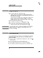
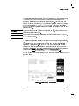
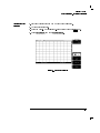
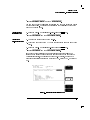
Cal status
The Cal Status function displays a screen similar to Figure 2-3.
Key Path
4Channel5
NNNNNNNNNNNNNNNNNNNNNNNNNNNNNNNN
NNNNNNNNNNNNNNNNNNNNNNNNNNNNN NNNNNNNNNNNNNNNNNNNNNNNNNNNNNNNN
Calibrate Cal Status
Figure 2-3. A typical Cal Status display.
Current Date
This is the current date and time. You can compare this to the last plug-in
module calibration time. That way you will know how long it has been since
the last plug-in module calibration was performed.
Current Frame
1Temp
This is the temperature change on the inside of the instrument since the last
mainframe calibration was performed. A positive number indicates how many
degrees warmer the mainframe is currently as compared to the temperature
of the mainframe at the last mainframe calibration.
2-13
Channel Setup Menu
Channel 1
Calibration
Status
The instrument displays Calibrated or Uncalibrated, depending on
whether the last plug-in module calibration is still valid. A calibration can be
invalidated if:
The mainframe has cycled power.
The plug-in has been repaired, reprogrammed, or removed from the
mainframe.
The instrument's operating temperature has changed and remains more
than 5 C from the temperature at which the Plug-in calibration was
performed.
Uncalibrated indicates the plug-in module vertical calibration is invalid.
Plug-in
The Plug-in function lists the model number, serial number, date, time, and
temperature delta. The temperature 1 is the temperature change from the
temperature of the mainframe when the last calibration was performed. If
this temperature 1 is greater than 65 C since the last mainframe calibration,
then you must perform a plug-in module calibration to achieve the specied
dc accuracy.
NNNNNNNNNNNNNNNNNNNNNNNNNNNNNNNNNNN
The Oset Zero function performs a quick oset calibration on the optical
channel. Since the primary source of calibration error on the optical channel
is oset drift, this function is useful:
after the plug-in module vertical calibration described in Chapter 3 has
been performed,
Offset zero
and
if the plug-in module has not been removed and reinstalled.
Performing an Oset Zero calibration is much faster than performing a
complete vertical calibration.
Key Path
NNNNNNNNNNNNNNNNNNNNNNN
O/E cal
4Channel5
NNNNNNNNNNNNNNNNNNNNNNNNNNNNN NNNNNNNNNNNNNNNNNNNNNNNNNNNNNNNNNNN
Calibrate Offset zero
The plug-in module is provided with factory optical calibrations at 1310 nm
and 1550 nm. The O/E Calibration function allows you to calibrate the
instrument for use at one additional user-dened wavelength between
1200 nm and 1600 nm. This calibration does not aect the factory
calibrations.
2-14
Channel Setup Menu
Calibrate probe Connect a voltage probe to the plug-in and then press:
NNNNNNNNNNNNNNNNNNNNNNNNNNNNNNNNNNNNNNNNNNNNNNN
NNNNNNNNNNNNNNNNNNNNNNNNNNNNNNNNNNNNNNNNNNNNNNN
Calibrate probe
The analyzer calibrates to the tip of the probe by setting the probe
attenuation to the actual attenuation ratio of the probe. The analyzer also
automatically compensates for any oset the probe may introduce. The CAL
signal is internally routed to the probe tip for HP probes.
Key Path
4Channel5
NNNNNNNNNNNNNNNNNNNNNNNNNNNNN NNNNNNNNNNNNNNNNNNNNNNNNNNNNNNNNNNNNNNNNNNNNNNN
Calibrate Calibrate probe
2-15
Channel Setup Menu
3
Calibration Overview
Calibration Overview
What you'll nd in this chapter
Factory Calibrations
User Calibrations|Optical and Electrical
Complete Calibration
This chapter describes the calibration of the mainframe and the plug-in
modules. It is intended to give you, or the calibration laboratory personnel,
an understanding of the various calibration procedures available, and how
they were intended to be used. There is a description of the calibration menu
included in the manuals provided with the plug-in modules and probes.
Proper calibration is critical to measurement accuracy and repeatability. The
HP 54750A/83480A and their associated modules and accessories require
that both factory and user calibrations be implemented at the recommended
intervals in order to perform measurements at their published specications.
This chapter is divided into three sections. The rst section describes
factory calibrations. A factory calibration consists of verifying instrument
performance to all specications. If an instrument fails to meet specications,
adjustment or repair may be necessary. For most users, this will mean
shipping the instrument back to an authorized service center. Some users
may purchase the required instrumentation and perform the factory timebase
calibrations themselves using the optional HP 83480A, 54750A Service
Guide.
The second part of the chapter addresses calibrations that are routinely
performed by the end user. Subsections in each of the two main sections
discuss the individual calibrations. In addition, there will be summary tables
at the end of each of these sections summarizing the main areas addressed.
The third part of the manual consists of a complete calibration summary
table at the end of the chapter. Both factory and user calibrations must be
3-2
Calibration Overview
CAUTION
Calibration interval
performed regularly in order to ensure proper measurement accuracy and
repeatability.
The input circuits can be damaged by electrostatic discharge (ESD). Avoid
applying static discharges to the front-panel input connectors. Before
connecting a coaxial cable to the connectors, momentarily short the center
and outer connectors of the cable together. Avoid touching the front panel
input connectors without rst touching the frame of the instrument. Be sure
that the instrument is properly earth-grounded to prevent buildup of static
charge. It is strongly recommended that an antistatic mat and wristband be
used when connecting to electrical channel inputs, particularly TDR inputs.
HP recommends that the factory calibration be performed on a periodic
basis. HP designs instruments to meet specications over the recommended
calibration interval provided that the instrument is operated within the
specied operating environment. To maintain specications, periodic
recalibrations are necessary. We recommend that the plug-in module be
calibrated at an HP service facility every 12 months. Users are encouraged to
adjust the calibration cycle based on their particular operating environment
or measurement accuracy needs.
Required warm-up time The instrument requires a 1 hour warm-up period before any of the
calibrations mentioned in this chapter are performed. It is not enough for the
instrument to be in the standby setting. It must be turned on and running for
the entire hour.
Remote operation
Remote programming commands for calibrations are included in the HP
83480A/HP 54750A Programming's Guide. Performing calibrations remotely
is slightly dierent than the operation of front-panel calibrations.
3-3
Factory Calibrations
The following calibrations are performed at the factory:
Mainframe Calibration
O/E Factory Wavelength Calibration
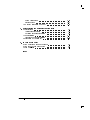
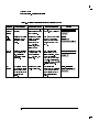
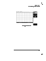
Table 3-1. Factory Calibration Summary
Calibration
Mainframe Calibration
O/E Factory Wavelength
Calibration
1
What is calibrated
Accuracy and
continuity of the
timescale
The photodetector
responsivity
Measurements
Aected
Recommended
Interval
Softkey Path
Annually at HP service 4Utility5
center or if operating Calibrate
temp has changed
and remains 5 C or Calibrate frame
more from calibration
temperature. See
service manual.
Not user accessible.1
Channels aected: Annual factory
optical. Amplitude re-calibration of
accuracy of all optical standard wavelengths.
channel
measurements.
Optical power meter
accuracy.
Channels aected:
optical & electrical.
All time base
measurements such
as rise time, fall time,
eye width, and jitter.
FFFFFFFFFFFFFFFFFFFFFFFFFF
FFFFFFFFFFFFFFFFFFFFFFFFFFFFFFFFFFFFFFFFFFF
Refer to \O/E User-Wavelength Calibration" in this chapter.
Mainframe Calibration
Mainframe calibration aects both optical and electrical measurements.
Mainframe calibration improves timebase accuracy. All timebase
measurements such as rise time, fall time, eye width, jitter, and so forth are
aected by the timebase accuracy.
3-4
Calibration Overview
Factory Calibrations
CAUTION
The calibration factors are stored in the nonvolatile RAM of the instrument.
There is a switch on the back panel of the instrument that allows the
mainframe calibration to be protected or unprotected. Next to the switch
there is a drawing that shows each switch's function and protected position.
Refer to the optional HP 83480A, 54750A Service Guide for more details
about the mainframe calibration, and the position of the rear-panel memory
protect switches.
To prevent access to the mainframe calibration switch, place a sticker over
the access hole to this switch.
CAUTION
Do not attempt a Mainframe calibration without consulting the HP 83480A,
54750A Service Guide.
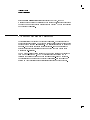
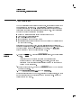
A mainframe calibration should be performed on a periodic basis, annually,
or when the ambient operating temperature has changed by and remains
5 C dierent than the operating temperature at which the last mainframe
calibration was performed. To see how much the operating temperature
has changed since the last mainframe calibration and the date of the last
mainframe calibration, check the Calibration status by pressing the following
key sequence: 4Utility5, Calibrate , and then Cal status on.
The temperature change is displayed at the top of the display as shown in the
following gure.
NNNNNNNNNNNNNNNNNNNNNNNNNNNNN
NNNNNNNNNNNNNNNNNNNNNNNNNNNNNNNN
Figure 3-1. Current Frame 1Temp condition
3-5
Calibration Overview
Factory Calibrations
If the Current Frame 1Temp listing is greater than 65 C, then the
mainframe should either be calibrated at the current operating temperature or
be placed in an ambient air temperature that is within 5 C of the temperature
of the current calibration.
O/E Factory Wavelength Calibration
Optical/electrical (O/E) factory wavelength calibration, compensates for the
photodetector responsivity. The accuracy of all optical channel measurements
is dependent on proper O/E calibration. O/E calibrations should be performed
annually. Most customers return their optical plug-ins to an authorized HP
service center for this calibration at the same time they are having their
mainframes re-calibrated.
The HP 83480-series optical modules have one or two standard wavelengths
(850 nm or 1310/1550 nm). The O/E Calibration function allows you to
calibrate the instrument for use at one additional user-dened wavelength.
This calibration does not aect the factory calibrations. See the following
section on User Calibrations for additional information on this procedure.
3-6
User Calibrations|Optical and Electrical
The following calibrations can be performed by the user:
O/E User Wavelength Calibration
Plug-in Module Vertical Calibration
Oset Zero Calibration
Dark Calibration
Probe Calibration
Channel Skew
External Scale
Electrical channels have calibration procedures for:
adjusting timebase skew, for matching propagation delay between channels,
probes, cables, and so forth
using external probes
Optical channels have calibration procedures for:
adjusting timebase skew
monitoring and adjusting internal osets
performing a user-dened O/E responsivity adjustment
CAUTION
The input circuits can be damaged by electrostatic discharge (ESD). Avoid
applying static discharges to the front panel input connectors. Before
connecting a coaxial cable to the connectors, momentarily short the center
and outer connectors of the cable together. Avoid touching the front panel
input connectors without rst touching the frame of the instrument. Be sure
the instrument is properly earth-grounded to prevent buildup of static charge.
An antistatic mat and wristband are strongly recommended, particularly
when working with TDR modules.
3-7
Calibration Overview
User Calibrations|Optical and Electrical
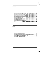
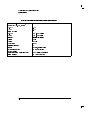
Table 3-2. Optical and Electrical Channel User Calibration Summary
Calibration
What is calibrated
Measurements Aected
Channels aected: optical. All Annual re-calibration of user
optical channel measurements dened non-factory wavelengths
at user wavelengths.
O/E User
Wavelength
Calibration
The photodetector
responsivity
Plug-in
Vertical
Calibration
Channels aected: optical &
electrical. Any optical or
electrical vertical
measurements such as
Vp to p, eye height,
extinction ratio, and the
optical power meter
Vertical oset is calibrated Channels aected: optical.
for the optical channel Any optical vertical
measurements including:
only. This calibration
doesn't include vertical Vp to p, eye height, and
extinction ratio.
scale accuracy.
Oset Zero
Calibration
Dark
Calibration
Vertical oset and vertical
scale accuracy for both
electrical and optical
channels.
Dark calibration measures
the channel oset signal
without any light present
and this value is used in
the extinction ratio
algorithm.
3-8
Recommended Interval
Key Path
4Optical
Channel Setup5
FFFFFFFFFFFFFFFFFFFFFFFFFF
Calibrate
O/E Cal
FFFFFFFFFFFFFFFFFFFFF
Perform after any power cycle or 4Utility5
once every 10 hours during
Calibrate
continuous use or if operating
Calibrate
temperature changes by more
than 2 C.
FFFFFFFFFFFFFFFFFFFFFFFFFF
FFFFFFFFFFFFFFFFFFFFFFFFFFFFFFFFFFFFFFFFFFFFFFFF
Plug-in
4Optical Channel Setup5
Perform a plug-in vertical
calibration in order to meet
Calibrate
published specications. Because Offset 0
the oset zero calibration
performs only the oset portion
of the plug-in vertical calibration,
it should only be used before fast
non-critical measurements.
4Shift5, 4Meas eye5
Channels aected: optical & Before extinction ratio
electrical. Extinction ratio. measurements if the vertical scale Extinction ratio
or oset has changed since the Dark Cal
last dark calibration or after a
plug-in vertical calibration is
performed.
FFFFFFFFFFFFFFFFFFFFFFFFFF
FFFFFFFFFFFFFFFFFFFFFFFF
FFFFFFFFFFFFFFFFFFFFFFFFFFFFFFFFFFFFFFFFFFFFFF
FFFFFFFFFFFFFFFFFFFFFFFF
Calibration Overview
User Calibrations|Optical and Electrical
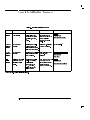
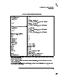
Table 3-3. Miscellaneous User Calibration Summary
Calibration
Probe
calibration
What is calibrated
Probe Attenuation
Channel Skew Calibrates out the small
dierences in delay
between channels. Useful
for looking at timing
dierences between
channels
External Scale Compensates for gain or
loss associated with
external devices
(calibrates vertical scale
to external device)
Measurements Aected
Recommended Interval
Channels aected: electrical. Whenever a probe is
Any electrical measurement connected
taken with the probe
Channels aected: optical &
electrical. Multiple channel
measurements, such as
Dierential TDR
Before multiple channel
measurements when
measuring timing dierences
between channels.
Channels aected: optical & Whenever using external
electrical. Any measurement devices (component or
taken through an external transducer)
device (component or
transducer)
Key Path
4Electrical
Channel Setup5
FFFFFFFFFFFFFFFFFFFFFFFFFF
Calibrate
Calibrate probe
FFFFFFFFFFFFFFFFFFFFFFFFFFFFFFFFFFFFFFFFFFF
4Channel
Setup5
FFFFFFFFFFFFFFFFFFFFFFFFFF
Calibrate
Skew
FFFFFFFFFFFFF
4Channel
Setup5
FFFFFFFFFFFFFFFFFFFFFFFFFFFFFFFFFFFFFFFFFFF
External Scale
O/E User-Wavelength Calibration
This optional optical/electrical (O/E) calibration is for optical measurements
only. It compensates for the photodetector's responsivity. The vertical
accuracy of all optical channel user wavelength measurements is dependent
on proper O/E user wavelength calibration. O/E user-wavelength calibrations
should be performed annually or whenever a new wavelength is being
measured. To perform a O/E user-wavelength calibration, a CW optical
source with a known optical output power level is required. Refer to the
specications for the plug-in module for the acceptable power level ranges.
3-9
Calibration Overview
User Calibrations|Optical and Electrical
NOTE
The optical channel calibration accuracy is heavily dependent on the accuracy to which you know the
optical source power. For best results, measure the optical source power with an optical power meter
such as the HP 8153A and use precision optical connectors. In addition, proper connector cleaning
procedures are essential to obtaining an accurate calibration.
To perform an O/E
user-wavelength
calibration
1. Press the plug-in module's front-panel optical channel 4SETUP5 key.
2. Press Calibrate , and then 4O/E cal5.
NNNNNNNNNNNNNNNNNNNNNNNNNNNNN
3. Input the correct wavelength, and follow the instructions on the screen.
Figure 3-2. Plug-in calibration menu
3-10
Calibration Overview
User Calibrations|Optical and Electrical
To use an O/E
user-wavelength
calibration
1. Press the plug-in module's front-panel optical channel 4SETUP5 key.
2. Press Bandwidth/wavelength and then Wavelength .
NNNNNNNNNNNNNNNNNNNNNNNNNNNNNNNN
NNNNNNNNNNNNNNNNNNNNNNNNNNNNNNNNNNNNNNNNNNNNNNNNNNNNNNNNNNNNNN
3. Press Usr wavelength and then Enter .
NNNNNNNNNNN
NNNNNNNNNNNNNNNNN
Plug-in Module Vertical Calibration
The plug-in module vertical calibration is for both optical and electrical
measurements. It allows the instrument to establish the calibration factors for
a specic plug-in when the plug-in is installed in the mainframe. The plug-in
calibration factors are valid only for the specic mainframe slot in which it
was calibrated. The plug-in vertical calibration establishes vertical accuracy.
A plug-in vertical calibration should be done if:
The mainframe has cycled power.
The plug-in has been repaired, reprogrammed, or removed from the
mainframe.
The instrument's operating temperature has changed and remains more
than 5 C from the temperature at which the Plug-in calibration was
performed.
To obtain the best measurement results, it is recommended that a user
vertical calibration be performed after every 10 hours of continuous use or if
the temperature has changed by greater than 2 C from the previous vertical
calibration.
To view the
temperature change
This procedure displays the temperature change that the instrument has
undergone since the last Plug-in Vertical Calibration.
1. Press the front-panel channel 4SETUP5 key.
2. Press Calibrate and then Cal status on.
NNNNNNNNNNNNNNNNNNNNNNNNNNNNN
NNNNNNNNNNNNNNNNNNNNNNNNNNNNNNNN
The current plug-in 1Temp value is listed for each installed module.
3-11
Calibration Overview
User Calibrations|Optical and Electrical
To perform a plug-in
module vertical
calibration
1. Remove any front-panel connections from electrical channels.
2. Cover the optical inputs for the optical channels.
3. Press 4Utility5, Calibrate. . . , and then Calibrate plug-in. . . .
NNNNNNNNNNNNNNNNNNNNNNNNNNNNNNNNNNNNNNNNNNNN
NNNNNNNNNNNNNNNNNNNNNNNNNNNNNNNNNNNNNNNNNNNNNNNNNNNNNNNNNNNNNNNNNNNN
4. Select the plug-in module to be calibrated, press 1 and 2 or 3 and 4 .
NNNNNNNNNNNNNNNNNNNNNNN
NNNNNNNNNNNNNNNNNNNNNNN
5. Press Start cal to start the calibration.
NNNNNNNNNNNNNNNNNNNNNNNNNNNNN
6. Follow the on-screen instructions.
No additional equipment is required to perform a plug-in vertical calibration.
Reference signals are both generated and routed internally, for the optical and
electrical channels. If you are prompted to connect the calibrator output to
the electrical channel during an optical vertical calibration, then the factory
O/E calibration has been lost. The module must then be returned to HP for
calibration.
Oset Zero Calibration
The oset zero calibration performs a quick oset calibration on the optical
channel for optical measurements. Since the primary source of calibration
error on the optical channel is oset drift, this function is useful between
the plug-in module vertical calibrations if the plug-in module has not been
removed or reinstalled and the operating temperature has not changed more
than 65 C. In order to ensure that instrument specications are met, perform
the plug-in vertical calibration.
Performing an oset zero calibration is much faster than performing a
complete vertical calibration. For critical measurements where oset
measurement uncertainty is important to consider, perform an oset zero
calibration between module vertical calibrations. Perform an oset zero
calibration if the vertical scale or oset changes.
3-12
Calibration Overview
User Calibrations|Optical and Electrical
To initiate an oset
calibration
1.
2.
3.
4.
Disconnect all inputs from the module being calibrated.
Cover all optical inputs.
Press the plug-in module's front-panel optical channel 4SETUP5 key.
Press Calibrate and then Offset zero .
NNNNNNNNNNNNNNNNNNNNNNNNNNNNN
NNNNNNNNNNNNNNNNNNNNNNNNNNNNNNNNNNN
Figure 3-3. Oset Zero Calibration
3-13
Calibration Overview
User Calibrations|Optical and Electrical
Dark Calibration
The dark calibration is for optical measurements, or electrical measurements
if an external O/E is being used. This calibration measures the optical
channel oset signal when there isn't any light present and then uses this
information in performing extinction ratio measurements. Dark calibrations
should be done for the following conditions:
Before any critical extinction ratio measurements are made
After a plug-in vertical calibration
If a module has been removed
If the mainframe power has been cycled
If extinction ratio measurements are being made after the vertical scale or
the oset has changed.
If the line power has been cycled, the dark calibration invokes either the
oset zero calibration or plug-in vertical calibration as needed. This increases
the time required for the dark calibration to complete. The Dark cal
softkey is located within the Extinction ratio menu.
NNNNNNNNNNNNNNNNNNNNNNNNNN
To initiate a dark
calibration
1. Press the 4Display5 key. Press the Color grade softkey, and set its setting
to on .
NNNNNNNNNNNNNNNNNNNNNNNNNNNNNNNNNNN
NNNNNNNN
Color grade must be enabled to perform an extinction ratio
measurement and a Dark calibration. In addition, the dark level
(amplitude when there is no signal present) must be on the screen to
perform a Dark calibration.
2. Press the blue shift key, and then the Meas eye softkey which is located
beneath the display.
3. Press Extinction ratio ... and then Dark cal .
Disconnect all inputs from the module, including the trigger signal, and block
any ambient light to the photodetector with a connector plug. Follow the
instructions on the screen.
NNNNNNNNNNNNNNNNNNNNNNNNNN
NNNNNNNNNNNNNNNNNNNNNNNNNNNNNNNNNNNNNNNNNNNNNNNNNNNNNNNNNNNNNN
3-14
NNNNNNNNNNNNNNNNNNNNNNNNNN
Calibration Overview
User Calibrations|Optical and Electrical
Figure 3-4. Dark calibration menu
Channel Skew Calibration
This calibration aects both optical and electrical measurements. The skew
calibration changes the horizontal position of a waveform on the display. The
skew calibration has a range of approximately 100 s. You can use skew to
compensate for the dierences in cable or probe lengths. It also allows you
to place the trigger edge at the center of the display when you are using a
power splitter connected between the channel and trigger inputs. Another
use for skew is when you are comparing two waveforms that have a timing
dierence. If you are interested in comparing the shapes of two waveforms
rather than the actual timing dierence, you can use skew to overlay one
waveform on top of the other waveform.
3-15
Calibration Overview
User Calibrations|Optical and Electrical
To skew two channels 1. Turn both channels on and overlay the signals vertically.
2. Expand the time base so that the rising edges are at about a 45 angle.
3. Press the plug-in module's front-panel channel 4SETUP5 key.
4. Press Calibrate and then Skew .
NNNNNNNNNNNNNNNNNNNNNNNNNNNNN
NNNNNNNNNNNNNN
5. Adjust the skew on one of the channels so that the rising edges overlap at
the 50% points.
Probe Calibration
Probe calibration applies to electrical measurements only. For active probes
such as the HP 54701A, which the instrument can identify through the probe
power connector, the instrument automatically adjusts the channel vertical
scale factors to the probe's nominal attenuation, even if a probe calibration is
not performed.
For passive probes or non-identied probes, the instrument adjusts the
vertical scale factors only if a probe calibration is performed. Probe
calibration allows the instrument to establish the gain and oset of specic
probes that are connected to a channel of the instrument, and then apply
those factors to the calibration of that channel.
The analyzer calibrates to the tip of the probe by setting the probe
attenuation to the actual attenuation ratio of the probe. The CAL signal is
internally routed to the probe tip for HP active probes.
The mainframe's CAL signal is a voltage source, therefore you can let the
instrument compensate for the actual characteristics of your probe by letting
the instrument calibrate to the tip of the probe. The instrument automatically
calibrates to the tip of the probe, sets the probe attenuation, and compensates
for any probe oset.
If you do not perform a probe calibration but want to use a passive probe,
enter the attenuation factor using the following steps:
1. Press the plug-in module's front-panel channel 4SETUP5 key.
3-16
Calibration Overview
User Calibrations|Optical and Electrical
2. Press External scale and then Attenuation .
You can use the probe calibration to calibrate any network, including probes
or cable assemblies. The instrument calibrates the voltage at the tip of the
probe or the cable input.
NNNNNNNNNNNNNNNNNNNNNNNNNNNNNNNNNNNNNNNNNNNN
NNNNNNNNNNNNNNNNNNNNNNNNNNNNNNNNNNN
To calibrate an HP
identiable probe
1. Press the plug-in module's front-panel-channel 4SETUP5 key.
2. Press Calibrate and then Calibrate Probe .
To calibrate a
non-identiable probe
1. Connect the voltage probe to the plug-in.
2. Attach the probe tip to the CAL hook that is located near the oppy disk
drive.
3. Press the plug-in module's front-panel channel 4SETUP5 key.
4. Press Calibrate and then Calibrate probe .
NNNNNNNNNNNNNNNNNNNNNNNNNNNNN
NNNNNNNNNNNNNNNNNNNNNNNNNNNNN
NNNNNNNNNNNNNNNNNNNNNNNNNNNNNNNNNNNNNNNNNNNNNNN
NNNNNNNNNNNNNNNNNNNNNNNNNNNNNNNNNNNNNNNNNNNNNNN
If the probe being calibrated has an attenuation factor that allows the
instrument to adjust the gain (in hardware) to produce even steps in the
vertical scale factors, the instrument will do so. Typically, probes have
standard attenuation factors such as divide by 10, divide by 20, or divide by
100.
Figure 3-5. Electrical Channel Calibrate Menu
3-17
Calibration Overview
User Calibrations|Optical and Electrical
To calibrate other
devices
The information in this section applies to both optical and electrical
measurements. Since the mainframe's CAL signal is a voltage source,
it cannot be used to calibrate to the probe tip when the units are set to
Ampere, Watt, or Unknown. Instead, set the external gain and external oset
to compensate for the actual characteristics of the probe or device. If you do
not know the actual characteristics, you can refer to the typical specications
that came with the probe or device.
1. Press the plug-in module's front-panel channel 4SETUP5 key.
2. Press External scale .
NNNNNNNNNNNNNNNNNNNNNNNNNNNNNNNNNNNNNNNNNNNN
3. Press Atten units Ratio, Attenuation 1:1, and then Units Ampere
(Volt, Watt, or Unknown).
4. Press Ext gain , and enter the actual gain characteristics of the probe or
device.
5. Press Ext offset , and enter the oset introduced by the probe or
device.
NNNNNNNNNNNNNNNNNNNNNNNNNNNNNNNNNNN
NNNNNNNNNNNNNNNNNNNNNNNNNNNNNNNNNNN
NNNNNNNNNNNNNNNNN
NNNNNNNNNNNNNNNNNNNNNNNNNN
NNNNNNNNNNNNNNNNNNNNNNNNNNNNNNNN
External Scale
Both optical and electrical channels have an External scale setting which
allows the user to enter in an oset value to compensate for gains or losses
not associated with the device under test. This feature is useful for adjusting
out the eects of devices such as test xtures and attenuators so that the
reading on the display gives the measurement value associated with only the
actual device under test.
To adjust the external
scale
1. Press the plug-in module's front-panel channel 4SETUP5 key.
2. Press External scale , and set the Atten units to \decibel".
NNNNNNNNNNNNNNNNNNNNNNNNNNNNNNNNNNNNNNNNNNNN
NNNNNNNNNNNNNNNNNNNNNNNNNNNNNNNNNNN
3. Press Attenuation , and enter the appropriate values.
NNNNNNNNNNNNNNNNNNNNNNNNNNNNNNNNNNN
3-18
Calibration Overview
User Calibrations|Optical and Electrical
Figure 3-6. External Scale Menu
3-19
Complete Calibration Summary
Table 3-4. Complete Calibration Summary
Calibration
Mainframe
Calibration
What is calibrated
Measurements Aected
Accuracy and continuity
of the timescale
Channels aected: optical &
electrical. All time base
measurements such as rise
time, fall time, eye width,
and jitter.
O/E Factory
Wavelength
Calibration
The photodetector
responsivity
O/E User
Wavelength
Calibration
The photodetector
responsivity
Plug-in
Vertical
Calibration
Vertical oset and vertical
scale accuracy for both
electrical and optical
channels.
1
Channels aected: optical &
electrical. Any optical or
electrical vertical
measurements such as
Vp to p, eye height,
extinction ratio, and the
optical power meter
Key Path
Annually at HP service center 4Utility5
or if operating temp has
Calibrate
changed and remains 5 C or Calibrate frame
more from calibration
temperature. See service
manual.
Annual factory re-calibration Not user accessible.1
of standard wavelengths.
FFFFFFFFFFFFFFFFFFFFFFFFFF
FFFFFFFFFFFFFFFFFFFFFFFFFFFFFFFFFFFFFFFFFFF
Channels aected: optical.
Amplitude accuracy of all
optical channel measurements.
Optical power meter accuracy.
Channels aected: optical. All Annual re-calibration of user
optical channel measurements dened non-factory
wavelengths
at user wavelengths.
Refer to \O/E User-Wavelength Calibration" in this chapter.
3-20
Recommended Interval
4Optical
Channel Setup5
FFFFFFFFFFFFFFFFFFFFFFFFFF
Calibrate
O/E Cal
FFFFFFFFFFFFFFFFFFFFF
Perform after any power cycle 4Utility5
or once every 10 hours
Calibrate
during continuous use or if Calibrate
operating temperature
changes by more than 2 C.
FFFFFFFFFFFFFFFFFFFFFFFFFF
FFFFFFFFFFFFFFFFFFFFFFFFFFFFFFFFFFFFFFFFFFFFFFFF
Plug-in
Calibration Overview
Table 3-4. Complete Calibration Summary (continued)
Calibration
Oset Zero
Calibration
Dark
Calibration
Probe
calibration
What is calibrated
Vertical oset is calibrated
for the optical channel
only. This calibration
doesn't include vertical
scale accuracy.
Dark calibration measures
the channel oset signal
without any light present
and this value is used in
the extinction ratio
algorithm.
Probe Attenuation
Measurements Aected
Recommended Interval
Key Path
4Optical Channel Setup5
Perform a plug-in vertical
calibration in order to meet Calibrate
published specications.
Offset 0
Because the oset zero
calibration performs only the
oset portion of the plug-in
vertical calibration, it should
only be used before fast
non-critical measurements.
4Shift5, 4Meas eye5
Channels aected: optical & Before extinction ratio
electrical. Extinction ratio. measurements if the vertical Extinction ratio
scale or oset has changed Dark Cal
since the last dark calibration
or after a plug-in vertical
calibration is performed.
4Electrical Channel Setup5
Channels aected: electrical. Whenever a probe is
Any electrical measurement connected
Calibrate
taken with the probe
Calibrate probe
Channels aected: optical.
Any optical vertical
measurements including:
Vp to p , eye height, and
extinction ratio.
FFFFFFFFFFFFFFFFFFFFFFFFFF
FFFFFFFFFFFFFFFFFFFFFFFF
FFFFFFFFFFFFFFFFFFFFFFFFFFFFFFFFFFFFFFFFFFFFFF
FFFFFFFFFFFFFFFFFFFFFFFF
FFFFFFFFFFFFFFFFFFFFFFFFFF
FFFFFFFFFFFFFFFFFFFFFFFFFFFFFFFFFFFFFFFFFFF
Channel Skew Calibrates out the small
dierences in delay
between channels. Useful
for looking at timing
dierences between
channels
External Scale Compensates for gain or
loss associated with
external devices
(calibrates vertical scale
to external device)
Channels aected: optical &
electrical. Multiple channel
measurements, such as
Dierential TDR
Before multiple channel
measurements when
measuring timing dierences
between channels.
Channels aected: optical & Whenever using external
electrical. Any measurement devices (component or
taken through an external transducer)
device (component or
transducer)
4Channel
Setup5
FFFFFFFFFFFFFFFFFFFFFFFFFF
Calibrate
Skew
FFFFFFFFFFFFF
4Channel
Setup5
FFFFFFFFFFFFFFFFFFFFFFFFFFFFFFFFFFFFFFFFFFF
External Scale
3-21
Calibration Overview
4
Specications and
Regulatory Information
Specications and Regulatory Information
This chapter lists the system specications and characteristics of the HP
83485A/B optical/electrical plug-in module when it is combined with
either the HP 83480A or HP 54750A mainframes. The specications and
characteristics for the mainframe are in the HP 83480A, 54750A User's
Guide. Specications apply over the temperature range +15 C to +35
C (unless otherwise noted) after the instrument's temperature has been
stabilized after 60 minutes of continuous operation.
In addition, you'll nd a declaration relating to regulatory information.
Specications
Specications described warranted performance. Unless otherwise noted,
corrected limits are given when specications are subject to minimization
with error-correction routines.
Characteristics
Characteristics provide useful, nonwarranted, information about the functions
and performance of the instrument. Characteristics are printed in italics.
Calibration cycle
HP designs instruments to meet specications over the recommended
calibration interval provided that the instrument is operated within the
specied operating environment. To maintain specications, periodic
recalibrations are necessary. We recommend that the plug-in module be
calibrated at an HP service facility every 12 months. Users are encouraged to
adjust the calibration cycle based on their particular operating environment
or measurement accuracy needs.
4-2
Specications
The following are specications used to test the HP 83485A/B plug-in module.
Specications are valid after a 1 hour warm-up period. See the HP 54701A
Active Probe Service Guide for complete probe specications.
Vertical specications
HP 83485A Electrical Channel Vertical Specications
Bandwidth (03 dB) on electrical or optical channel
dc Accuracy|single marker1
12.4 GHz bandwidth
20 GHz
dc to 12.4 or 20 GHz, user selectable
60.4% of full scale
62 mV 61.5% (reading 0 channel oset)
6 (2%/C) (1Tcal2 ) (reading) 0 0.4%/hr (1Time3 ) (reading)
60.4% of full scale
62 mV 63% (reading 0 channel oset)
6 (2%/C) (1Tcal2 ) (reading) 0 0.4%/hr (1Time3) (reading)
dc Dierence|two marker accuracy on same channel1
12.4 GHz
60.8% of full scale
61.5% of delta marker reading
6 (2%/C) (1Tcal2 ) (reading) 0 0.4%/hr (1Time3) (reading)
20 GHz
60.8% of full scale
63% of delta marker reading
6 (2%/C) (1Tcal2 ) (reading) 0 0.4%/hr (1Time3) (reading)
is recommended that a user vertical calibration be performed after every 10 hours of continuous use or if the temperature has changed by greater than 2 C
from the previous vertical calibration.
2 Where 1Tcal represents the temperature change in Celsius from the last user vertical calibration. Note that the temperature term goes to zero upon
execution of a vertical calibration.
3 Where 1Time represents the time since the last user vertical calibration. The uncertainty due to time typically stabilizes after 24 hours. This term goes to
zero upon execution of a vertical calibration.
1 It
4-3
Specications and Regulatory Information
Specications
HP 83485A Electrical Channel Vertical Specications (continued)
Transition Time (10%{90%) characteristic,
calculated from T=0.35/BW, electrical
12.4 GHz
20 GHz
Maximum RMS Noise
12.4 GHz
20 GHz
Scale Factor
Minimum
Maximum
dc Oset Range
Nominal Input Impedance
Connectors
Input Reection/Return Loss
Number of Channels
Dynamic Range/Maximum Specied Input Power
Maximum Safe Input
4-4
28.2 ps
17.5 ps
0.5 mV (0.25 mV typical)
1.0 mV (0.5 mV typical)
full scale is eight divisions
1 mV/div
100 mV/div
6500 mV
50 3.5mm (m), channel and trigger
5% for 30 ps rise time
1
6400 mV relative to channel oset
62V + peak ac (+16 dBm)
Specications and Regulatory Information
Specications
HP 83485A Optical Channel Vertical Specications
Bandwidth (03 dB) on electrical or optical channel
dc Accuracy|single marker1
12.4 GHz, ltered2
20 GHz2
dc to 12.4 or 20 GHz (user selectable)
625 W
62% (reading 0 channel oset)
6 (2%/C) (1Tcal3 ) (reading) 0 0.4%/hr (1Time4 ) (reading)
625 W
64% (reading 0 channel oset)
6 (2%/C) (1Tcal3 ) (reading) 0 0.4%/hr (1Time4) (reading)
dc Dierence|two marker accuracy on same channel1
62% of delta reading
12.4 GHz, ltered2
6 (2%/C) (1Tcal3 ) (reading) 0 0.4%/hr (1Time4) (reading)
2
20 GHz
64% of delta reading
6 (2%/C) (1Tcal3 ) (reading) 0 0.4%/hr (1Time4) (reading)
Transition Time (10%{90%) characteristic,
calculated from T=0.48/BW, optical
12.4 GHz
40 ps
20 GHz
25 ps
STM-16/OC-48 lter
190 ps
STM-4/OC-12 lter
750 ps
STM-1/OC-3 lter
3 ns
Maximum RMS Noise
12.4 GHz, ltered
12 W (8 W typical)
20 GHz
25 W (15 W typical)
Scale Factor
full scale is eight divisions
Minimum
20 W/div
Maximum
500 W/div
dc Oset Range
+1 to 03 mW (referenced two divisions
below center screen)
Connectors
User selected option, 9/125 m single mode ber
Input Reection/Return Loss
>33 dB for HMS-10/HP interface connector
is recommended that a user vertical calibration be performed after every 10 hours of continuous use or if the temperature has changed by greater than 2 C
from the previous vertical calibration.
2 Referenced to average power meter.
3 Where 1Tcal represents the temperature change in Celsius from the last user vertical calibration. Note that the temperature term goes to zero upon
execution of a vertical calibration.
4 Where 1Time represents the time since the last user vertical calibration. The uncertainty due to time typically stabilizes after 24 hours. This term goes to
zero upon execution of a vertical calibration.
1 It
4-5
Specications and Regulatory Information
Specications
HP 83485A Optical Channel Vertical Specications (continued)
Filtered Response
Calibrated Wavelengths
Average power Monitor
Specied Operating Range
Factory Calibrated Accuracy (20 C{30 C)
User Calibrated Accuracy1 <5 C temp change
Number of Channels
Dynamic Range/Maximum Specied Input Power
Maximum Safe Input
Wavelength Range
1
Measured response conforms to
ITU-TS G.957 and GR-253-CORE
for STM-16, OC-48 (Option 034)
or STM-4, OC-12 (Option 032)
or STM-1, OC-3 (Option 030)
1310 nm and 1550 nm
030 dBm to +3 dBm (1 W to 2 mW)
65% of reading 6100 nW 6 connector uncertainty
62% of reading 6100 nW 6 power meter accuracy
1
2 mW
10 mW peak
1200{1600 nm
A user calibration can be performed with average optical power levels from 100 to 2000 W, however, the instrument optical accuracy specication is only
vaild for average optical calibration powers form 500 to 2000 W.
4-6
Specications and Regulatory Information
Specications
HP 83485B Electrical Channel Vertical Specications
Bandwidth (03 dB)
dc Accuracy|single voltage marker1
18 GHz
40 GHz
Transition Time (10% to 90%, calculated from
T=0.35/bandwidth)
Maximum RMS Noise
18 GHz
40 GHz
Scale Factor (full scale is eight divisions)
Minimum
Maximum
dc Oset Range
Inputs:
Dynamic Range
Maximum Safe Input Voltage
Nominal Impedance
Reections
Connector
dc to 40 GHz, or dc to 18 GHz (user selectable)
60.4% of full scale
62 mV 61.5% (reading 0 channel oset)
6 (2%/C) (1Tcal2 ) (reading)
60.4% of full scale
62 mV 63% (reading 0 channel oset)
6 (2%/C) (1Tcal) (reading)2
9 ps (40 GHz BW)
19.5 ps (18 GHz BW)
0.5 mV (0.25 mV typical)
1.0 mV (0.5 mV typical)
1 mV/div
100 mV/div
6500 mV
6400 mV relative to channel oset
16 dBm peak ac 62V dc
50 5% for 20 ps rise time
2.4mm (m)
is recommended that a user vertical calibration be performed after every 10 hours of continuous use or if the temperature has changed by greater than 2 C
from the previous vertical calibration.
2 Where 1Tcal represents the temperature change in Celsius from the last user vertical calibration. Note that the temperature term goes to zero upon
execution of a vertical calibration.
1 It
4-7
Specications and Regulatory Information
Specications
HP 83485B Optical Channel Vertical Specications
Bandwidth (03 dB)
dc Accuracy1
(Optical channel referenced to
average power meter)
dc Dierence1
(two marker accuracy, same channel,
referenced to average power monitor)
Transition Time (10% to 90%) characteristic,
calculated from T=0.48/bandwidth, optical
Maximum RMS Noise
Scale Factor (full scale is eight divisions)
Minimum
Maximum
dc Oset Range
Connector Type
Input Return Loss
Filtered Bandwidth
Calibrated Wavelengths
Average Power Monitor
Specied Operating Range
Factory Calibrated Accuracy (20C to 30 C)
User Calibrated Accuracy (<5 C temp change)
Maximum Specied Input Power
Maximum Safe Input
Wavelength Range
dc to 30 GHz
650 W 64% of (reading 0 channel oset)
6 (2%/ C) (1Tcal 2) (reading)
64% of delta reading
6 (2%/ C) (1Tcal 2) (reading)
<16 ps
<30 W (<15 W typical)
20 W/div
500 W/div
+1 mW to 03 mW, referenced
to two divisions above bottom of screen
9/125 m single mode, user selectable connector option
30 dB (HMS-10/HP connector)
Fourth or fth order Bessel-Thomson lter,
3 dB frequency 7.465 GHz
1310 nm and 1550 nm
027 dBm to +3 dBm (2 W to 2 mW)
65% of reading 6100 nW 6
connector uncertainty
62% of reading 6100 nW 6power-meter uncertainty
2 mW
10 mW peak
1000 to 1600 nm
It is recommended that a user vertical calibration be performed after every 10 hours of continuous use or if the temperature has changed by greater than 2 C
from the previous vertical calibration.
2 Where 1Tcal represents the temperature change in Celsius from the last user vertical calibration. Note that the temperature term goes to zero upon
execution of a vertical calibration.
1
4-8
Specications and Regulatory Information
Specications
Environmental specications
Temperature
Operating
Non-operating
Humidity
Operating
Non-operating
Electrical and Optical Channels
15 C to +35 C
040 C to +70 C
up to 90% relative humidity (non-condensing) at 35 C
up to 95% relative humidity (non-condensing) at 65 C
Power Requirements
Supplied by mainframe.
Weight
Net
Shipping
approximately 1.2 kg (2.6 lb.)
approximately 2.1 kg (4.6 lb.)
4-9
Characteristics
The following characteristics are typical for the HP 83485A/B optical/electrical
plug-in module. See the HP 54701A Active Probe Service Guide for complete
probe characteristics.
Trigger input characteristics
Electrical and Optical Channels
Nominal Impedance
Input Connector
Trigger Level Range
Maximum Safe Input Voltage
Percent Reection
50 3.5 mm (m)
61 V
62 Vdc + ac peak (+16 dBm)
10% for 100 ps rise time
Refer to the HP 83480A, 54750A User's Guide for trigger specications.
4-10
Declaration of Conformity
4-11
Specications and Regulatory Information
5
In Case of Diculty
In Case of Diculty
What you'll nd in this chapter
This chapter provides a list of suggestions for you to follow if the plug-in module fails to operate. A
list of messages that may be display is also included.
For complete service information, refer to the optional
.
HP 83485A/B Service Guide
Review the procedure being performed when the problem occurred. Before
calling Hewlett-Packard or returning the unit for service, a few minutes spent
performing some simple checks may save waiting for your instrument to be
repaired.
5-2
In Case of Diculty
If the mainframe does not operate
If the
mainframe
does not
operate
Please make the following checks:
Is the line fuse good?
Does the line socket have power?
Is the unit plugged in to the proper ac power source?
Is the mainframe turned on?
Is the rear-panel line switch set to on?
Will the mainframe power up without the plug-in module installed?
If the mainframe still does not power up, refer to the optional HP 83480A,
54750A Service Guide or return the mainframe to a qualied service
department.
5-3
In Case of Diculty
If the plug-in
does not
operate
1. Make the following checks:
Is the plug-in module rmly seated in the mainframe slot?
Are the knurled screws at the bottom of the plug-in module nger-tight?
Is a trigger signal connected to a trigger input?
If other equipment, cables, and connectors are being used with the
plug-in module are they connected properly and operating correctly?
Review the procedure for the test being performed when the problem
appeared. Are all the settings correct? Can the problem be reproduced?
Are the connectors clean? See \Cleaning Connections for Accurate
Measurements" in Chapter 1 for more information about cleaning the
connectors.
2. Perform the following procedures:
Make sure the instrument is ready to acquire data by pressing Run .
NNNNNNNNNNN
Find any signals on the channel inputs by pressing 4Autoscale5.
See if any signals are present at the channel inputs by pressing:
4Trigger5
NNNNNNNNNNNNNNNNN
Sweep
NNNNNNNNNNNNNNNNNNNNNNN
freerun
After viewing the signal, press triggered .
NNNNNNNNNNNNNNNNNNNNNNNNNNNNN
Make sure Channel Display is on by pressing:
4Channel5
Display on off on
NNNNNNNNNNNNNNNNNNNNNNNNNNNNNNNNNNNNNNNNNNNN
Make sure the channel oset is adjusted so the waveform is not clipped
o the display.
If you are using the plug-in module only as a trigger source, make sure
at least one other channel is turned on.
If all of the channels are turned o, the mainframe will not trigger.
5-4
In Case of Diculty
If the plug-in does not operate
Make sure the mainframe identies the plug-in module by pressing:
4Utility5
NNNNNNNNNNNNNNNNNNNNNNNNNNNNNNNNNNNNNNNNNNNNNNNNNN
System config...
The calibration status of the plug-in modules is listed near the bottom of
the display, in the box labeled \Plug-ins". If the model number of the
plug-in module is listed next to the appropriate slot number, then the
mainframe has identied the plug-in.
If \~known" is displayed instead of the model number of the plug-in
module, remove and reinsert the plug-in module in the same slot. If
\~known" is still displayed, then the memory contents of the plug-in
module are corrupt. Refer to the optional HP 83485A/B Service Guide
or contact a qualied service department.
If all of the above steps check out okay, and the plug-in module still does not
operate properly, then the problem is beyond the scope of this book. Refer to
the optional HP 83485A/B Service Guide or return the plug-in module to a
qualied service department.
5-5
In Case of Diculty
Error
Messages
The following error messages are for the plug-in module. Typically, the
error messages indicate there is a problem with either the plug-in or the
mainframe.
This section explains what the messages mean and oers a few suggestions
that might help resolve the error condition. If the suggestions do not
eliminate the error message, then additional troubleshooting is required that
is beyond the scope of this book. Refer to the optional HP 83485A/B Service
Guide and HP 83480A, 54750A Service Guide for additional troubleshooting
information.
Additional error messages are listed in the HP 83480A, 54750A User's Guide
for the mainframe.
Memory error occurred The mainframe could not correctly read the contents of the memory in the
plug-in.
in plug-in : Try
reinstalling plug-in
1. Remove and reinstall the plug-in module.
Each time a plug-in is installed, the mainframe rereads the plug-in
module's memory.
2. Verify the plug-in module is rmly seated in the mainframe slot.
3. Verify the knurled screws at the bottom of the plug-in module are
nger-tight.
4. Install the plug-in in a dierent slot in the mainframe.
Busy timeout occurred The mainframe is having trouble communicating with the plug-in module.
Make sure there is a good connection between the mainframe and the plug-in
with plug-in : Try
module.
reinstalling plug-in
1. Remove and reinstall the plug-in module.
2. Verify the plug-in module is rmly seated in the mainframe slot.
3. Verify the knurled screws at the bottom of the plug-in module are
nger-tight.
4. Install the plug-in in a dierent slot in the mainframe.
5-6
In Case of Diculty
Communication failure An illegal hardware state is detected at the mainframe to plug-in module
exists at slot : Service interface of the specied slot.
is required
If the slot is empty, there is a mainframe hardware problem. Refer to the
HP 83480A, 54750A Service Guide.
If a plug-in is installed in the slot, there is a plug-in module hardware
problem. Refer to the optional HP 83485A/B Service Guide.
ID error occurred in
plug-in : Service is
required
The information read from the plug-in module's memory does not match the
hardware in the plug-in module. This can be caused by a communication
problem between the mainframe and the plug-in module. Make sure there is
a good connection between the mainframe and the plug-in.
1. Remove and reinstall the plug-in module.
2. Verify the plug-in module is rmly seated in the mainframe slot.
3. Verify the knurled screws at the bottom of the plug-in module are
nger-tight.
4. The HP 54750A mainframe does not accept the HP 83485A/B
optical/electrical plug-in module. To use the optical plug-in modules,
a rmware upgrade must rst be installed. Order the HP 83480K
communications rmware kit and follow the installation instructions.
5. The HP 83480A, 54750A mainframes do not accept plug-in modules
designed for use with the HP 54710A, 54720A.
Cal not possible
The power is too low to perform a user O/E calibration.
5-7
In Case of Diculty
Index
Index
A
B
C
accessories
connection devices, 1-5
optional, 1-5
accuracy performance, 1-11
active probe, 2-7
attenuation
range, 2-10
Attenuation softkey, 2-10
attenuator
scaling, 2-9
Atten units softkey, 2-9
automatic measurement, 2-5
auxiliary power connector, 1-10
Bandwidth key, 2-8
Bandwidth/Wavelength . . . softkey, 2-7
Bessel-Thomson lter, 1-2, 2-8
Calibrate probe softkey, 2-15
Calibrate softkey, 2-11
calibration
external scale, 3-15
factory, 3-4
mainframe, 3-4
O/E, 2-14, 3-6
O/E converters, 3-15
O/E user wavelength, 3-9
oset zero, 2-14, 3-12
overview, 3-2
plug-in module vertical calibration, 3-11
probe, 3-16
probes, 3-15
skew, 3-15
status, 5-5
user, 3-7
validity, 2-14
vertical, 1-11
voltage probe, 3-16
CAL signal, 2-15
Cal status softkey, 2-13
channel
Index-2
display, 2-5
electrical, 1-2
input, 1-10
optical, 1-2
scale, 2-10
setup, 2-2
Channel 1 Calibration Status message, 2-14
Channel autoscale softkey, 2-9
Channel key, 2-2
characteristics, 4-10
cleaning
adapters, 1-16
non-lensed connectors, 1-15
cleaning ber-optic connections, 1-13, 1-15
connection devices, 1-5
connector care, 1-13
Current Date message, 2-13
Current Frame 1Temp message, 2-13
customer assistance, v
D
E
decibel calculation, 2-9
declaration of conformity, 4-10
description of the plug-in module, 1-2
digital oset, 2-7
Display softkey, 2-5
electrical channel, 1-2
environmental specications , 4-9
HP 83485A vertical specications, 4-3
HP 83485B specications, 4-7
trigger input characteristics, 4-10
weight, 4-9
environmental specications , 4-9
error messages, 5-6{7
extender cables, 1-12
external scale calibration, 3-15
External scale . . . softkey, 2-9
external trigger
input, 1-10
level, 1-12
Ext gain softkey, 2-11
Ext oset softkey, 2-11
Index-3
F
H
I
K
M
O
factory calibration, 3-4
ber-optic cables
cleaning connections, 1-13
inspecting, 1-14
front panel overview, 1-10
horizontal waveform, 2-12
index-matching compounds, 1-13
index matching gel, 1-13
input connector, 1-13
inspecting
cables, 1-14
installing the plug-in module, 1-11
key conventions, 1-6
mainframe calibration, 3-4
mainframe troubleshooting, 5-3
marker value, 2-10
math function, 2-5
menu overview, 1-6
O/E calibration, 3-6
O/E cal softkey, 2-14
O/E converter calibration, 3-15
O/E user wavelength calibration, 3-9
oset, 2-5{7, 2-10, 2-14
Oset softkey, 2-7
oset zero calibration, 3-12
Oset zero softkey, 2-14
optical channel, 1-2, 2-7
environmental specications , 4-9
HP 83485A specications, 4-4
HP 83485B specications, 4-7
trigger input characteristics, 4-10
vertical specications, 4-4
weight, 4-9
optical-to-electrical converter scaling, 2-9
optional accessories, 1-5
options, 1-4
ordering information, 1-4
Index-4
P
R
S
T
plug-in message, 2-14
plug-in module
description, 1-2
features, 1-8
front panel, 1-10
installation, 1-11
purpose, 1-8
specications, 4-3{9
troubleshooting, 5-4
weight, 4-9
plug-in module vertical calibration, 3-11
power level, 2-7
power requirements, 4-9
probe
attenuation, 2-10, 2-15
attenuation factor, 2-9
characteristics, 2-11
power, 2-7
power connector, 1-10
probe calibration, 3-15, 3-16
pulse parameter measurements, 2-5
RF connectors, 1-11
safety information, iv, 1-12
Scale softkey, 2-6
shifted function keys, 1-6
skew calibration, 3-15
Skew softkey, 2-12
softkey
menu, 1-10
overview, 1-6
SONET/SDH lter, 1-2, 2-8
specications, 4-7
plug-in module, 4-3{9
technical assistance, v
temperature change, 2-13{14
trigger
external, 1-12
input characteristics, 4-10
level, 2-10
source, 2-5
troubleshooting, 5-2{7
Index-5
U
V
W
Units softkey, 2-6, 2-10
user calibrations, 3-7
vertical
calibration, 1-11
measurement, 2-10
scale, 2-5{6, 2-9
specications, 4-3
waveform, 2-7
voltage
measurement, 2-10
probe, 2-15
voltage probe calibration, 3-16
warranty information, vii
wattage measurement, 2-10
waveform
display, 2-5
horizontal, 2-12
Wavelength key, 2-8
wavelength settings, 2-7
weight of plug-in module, 4-9
Index-6