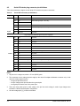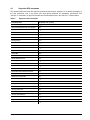
1
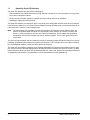
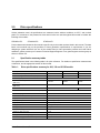
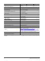
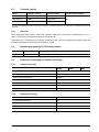
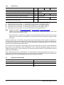
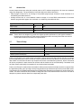
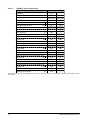
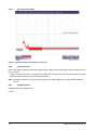
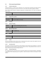
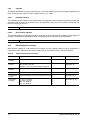
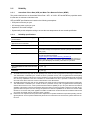
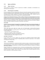
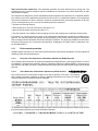
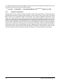
Product Manual
Pulsar
TM
ST9200011FS
ST9100011FS
ST950011FS
100596473
Rev. A
April 2010
Revision history
Revision
Rev. A
Date
04/05/10
Sheets affected or comments
Initial release.
© 2010 Seagate Technology LLC. All rights reserved.
Publication number: 100596473, Rev. A. April 2010
Seagate Technology and the Wave logo are registered trademarks of Seagate Technology LLC in
the United States and/or other countries. Pulsar and SeaTools are either trademarks or registered
trademarks of Seagate Technology LLC or one of its affiliated companies in the United States and/or
other countries. All other trademarks or registered trademarks are the property of their respective
owners.
No part of this publication may be reproduced in any form without written permission of Seagate
Technology LLC. Call 877-PUB-TEK1(877-782-8651) to request permission.
When referring to drive capacity, one gigabyte, or GB, equals one billion bytes and one terabyte, or
TB, equals one trillion bytes. Your computer's operating system may use a different standard of
measurement and report a lower capacity. In addition, some of the listed capacity may be used for
formatting and other functions, and thus will not be available for data storage. Seagate reserves the
right to change, without notice, product offerings or specifications.
Contents
1.0
Introduction. . . . . . . . . . . . . . . . . . . . . . . . . . . . . . . . . . . . . . . . . . . . . . . . . . . . . . . . . . . . . . . . . . . 1
1.1
About the Serial ATA interface . . . . . . . . . . . . . . . . . . . . . . . . . . . . . . . . . . . . . . . . . . . . . . 2
2.0
Drive specifications . . . . . . . . . . . . . . . . . . . . . . . . . . . . . . . . . . . . . . . . . . . . . . . . . . . . . . . . . . . . 3
2.1
Specification summary tables . . . . . . . . . . . . . . . . . . . . . . . . . . . . . . . . . . . . . . . . . . . . . . . 3
2.2
Formatted capacity . . . . . . . . . . . . . . . . . . . . . . . . . . . . . . . . . . . . . . . . . . . . . . . . . . . . . . . 5
2.2.1
LBA mode . . . . . . . . . . . . . . . . . . . . . . . . . . . . . . . . . . . . . . . . . . . . . . . . . . . . . . 5
2.3
Default logical geometry for ATA based systems . . . . . . . . . . . . . . . . . . . . . . . . . . . . . . . . 5
2.4
Performance, Recording and interface technology . . . . . . . . . . . . . . . . . . . . . . . . . . . . . . . 5
2.4.1
Interface technology. . . . . . . . . . . . . . . . . . . . . . . . . . . . . . . . . . . . . . . . . . . . . . . 5
2.4.2
Recording technology . . . . . . . . . . . . . . . . . . . . . . . . . . . . . . . . . . . . . . . . . . . . . 5
2.4.3
Performance. . . . . . . . . . . . . . . . . . . . . . . . . . . . . . . . . . . . . . . . . . . . . . . . . . . . . 6
2.5
Physical characteristics . . . . . . . . . . . . . . . . . . . . . . . . . . . . . . . . . . . . . . . . . . . . . . . . . . . 6
2.6
Access time . . . . . . . . . . . . . . . . . . . . . . . . . . . . . . . . . . . . . . . . . . . . . . . . . . . . . . . . . . . . . 7
2.7
Time to Ready . . . . . . . . . . . . . . . . . . . . . . . . . . . . . . . . . . . . . . . . . . . . . . . . . . . . . . . . . . . 7
2.8
Power specifications . . . . . . . . . . . . . . . . . . . . . . . . . . . . . . . . . . . . . . . . . . . . . . . . . . . . . . 8
2.8.1
Power consumption . . . . . . . . . . . . . . . . . . . . . . . . . . . . . . . . . . . . . . . . . . . . . . . 8
2.8.2
Conducted noise . . . . . . . . . . . . . . . . . . . . . . . . . . . . . . . . . . . . . . . . . . . . . . . . 12
2.8.3
Voltage tolerance . . . . . . . . . . . . . . . . . . . . . . . . . . . . . . . . . . . . . . . . . . . . . . . . 12
2.9
Environmental specifications . . . . . . . . . . . . . . . . . . . . . . . . . . . . . . . . . . . . . . . . . . . . . . . 13
2.9.1
Ambient temperature . . . . . . . . . . . . . . . . . . . . . . . . . . . . . . . . . . . . . . . . . . . . . 13
2.9.2
Temperature gradient. . . . . . . . . . . . . . . . . . . . . . . . . . . . . . . . . . . . . . . . . . . . . 13
2.9.3
Humidity . . . . . . . . . . . . . . . . . . . . . . . . . . . . . . . . . . . . . . . . . . . . . . . . . . . . . . . 13
2.9.4
Altitude . . . . . . . . . . . . . . . . . . . . . . . . . . . . . . . . . . . . . . . . . . . . . . . . . . . . . . . . 13
2.9.5
Shock . . . . . . . . . . . . . . . . . . . . . . . . . . . . . . . . . . . . . . . . . . . . . . . . . . . . . . . . . 13
2.9.6
Vibration . . . . . . . . . . . . . . . . . . . . . . . . . . . . . . . . . . . . . . . . . . . . . . . . . . . . . . . 14
2.10
Electromagnetic immunity . . . . . . . . . . . . . . . . . . . . . . . . . . . . . . . . . . . . . . . . . . . . . . . . . 14
2.11
Reliability . . . . . . . . . . . . . . . . . . . . . . . . . . . . . . . . . . . . . . . . . . . . . . . . . . . . . . . . . . . . . . 15
2.11.1
Annualized Failure Rate (AFR) and Mean Time Between Failures (MTBF) . . . 15
2.11.2
Reliability specifications . . . . . . . . . . . . . . . . . . . . . . . . . . . . . . . . . . . . . . . . . . . 15
2.12
Agency certification . . . . . . . . . . . . . . . . . . . . . . . . . . . . . . . . . . . . . . . . . . . . . . . . . . . . . . 16
2.12.1
Safety certification . . . . . . . . . . . . . . . . . . . . . . . . . . . . . . . . . . . . . . . . . . . . . . . 16
2.12.2
Electromagnetic compatibility. . . . . . . . . . . . . . . . . . . . . . . . . . . . . . . . . . . . . . . 16
2.12.3
FCC verification . . . . . . . . . . . . . . . . . . . . . . . . . . . . . . . . . . . . . . . . . . . . . . . . . 16
2.13
Environmental protection . . . . . . . . . . . . . . . . . . . . . . . . . . . . . . . . . . . . . . . . . . . . . . . . . . 17
2.13.1
European Union Restriction of Hazardous Substances (RoHS) Directive . . . . . 17
2.13.2
China Restriction of Hazardous Substances (RoHS) Directive . . . . . . . . . . . . . 17
2.14
Corrosive environment . . . . . . . . . . . . . . . . . . . . . . . . . . . . . . . . . . . . . . . . . . . . . . . . . . . 18
3.0
Configuring and mounting the drive . . . . . . . . . . . . . . . . . . . . . . . . . . . . . . . . . . . . . . . . . . . . .
3.1
Handling and static-discharge precautions . . . . . . . . . . . . . . . . . . . . . . . . . . . . . . . . . . . .
3.2
Configuring the drive . . . . . . . . . . . . . . . . . . . . . . . . . . . . . . . . . . . . . . . . . . . . . . . . . . . . .
3.3
Serial ATA cables and connectors . . . . . . . . . . . . . . . . . . . . . . . . . . . . . . . . . . . . . . . . . .
3.4
Drive mounting . . . . . . . . . . . . . . . . . . . . . . . . . . . . . . . . . . . . . . . . . . . . . . . . . . . . . . . . .
3.5
Cooling . . . . . . . . . . . . . . . . . . . . . . . . . . . . . . . . . . . . . . . . . . . . . . . . . . . . . . . . . . . . . . .
19
19
20
20
21
22
4.0
Serial ATA (SATA) interface . . . . . . . . . . . . . . . . . . . . . . . . . . . . . . . . . . . . . . . . . . . . . . . . . . . .
4.1
Hot-Plug compatibility . . . . . . . . . . . . . . . . . . . . . . . . . . . . . . . . . . . . . . . . . . . . . . . . . . . .
4.2
Serial ATA device plug connector pin definitions. . . . . . . . . . . . . . . . . . . . . . . . . . . . . . . .
4.3
Supported ATA commands . . . . . . . . . . . . . . . . . . . . . . . . . . . . . . . . . . . . . . . . . . . . . . . .
4.3.1
Identify Device command. . . . . . . . . . . . . . . . . . . . . . . . . . . . . . . . . . . . . . . . . .
4.3.2
Set Features command . . . . . . . . . . . . . . . . . . . . . . . . . . . . . . . . . . . . . . . . . . .
4.3.3
S.M.A.R.T. commands . . . . . . . . . . . . . . . . . . . . . . . . . . . . . . . . . . . . . . . . . . . .
23
23
24
25
27
34
35
5.0
Seagate Technology support services . . . . . . . . . . . . . . . . . . . . . . . . . . . . . . . . . . . . . . . . . . . . 37
Pulsar Product Manual, Rev. A
i
ii
Pulsar Product Manual, Rev. A
List of Figures
Figure 1.
Figure 2.
Figure 3.
Figure 4.
Typical 5V startup and operation current profile . . . . . . . . . . . . . . . . . . . . . . . . . . . . . . . . . . .
Attaching SATA cabling . . . . . . . . . . . . . . . . . . . . . . . . . . . . . . . . . . . . . . . . . . . . . . . . . . . . .
Mounting dimensions—top, side and end view . . . . . . . . . . . . . . . . . . . . . . . . . . . . . . . . . . .
Air flow . . . . . . . . . . . . . . . . . . . . . . . . . . . . . . . . . . . . . . . . . . . . . . . . . . . . . . . . . . . . . . . . . .
Pulsar Product Manual, Rev. A
12
20
21
22
iii
1.0
Introduction
This manual describes the functional, mechanical and interface specifications for the following Seagate
PulsarTM model drives:
ST9200011FS
ST9100011FS
ST950011FS
These drives provide the following key features:
• Single Layer Cell (SLC) NAND Flash storage.
• High instantaneous (burst) data-transfer rates (up to 300MB/s).
• Parallel flash access channels.
• State-of-the-art on-the-fly error-correction algorithms.
• Native Command Queueing with command ordering to increase performance in demanding applications.
• Highly integrated hardware functions.
• Power loss data protection.
• Data Set Management with Trim Support.
• Silent operation.
• SeaTools diagnostic software performs a drive self-test that eliminates unnecessary drive returns.
• Support for S.M.A.R.T. drive monitoring and reporting.
• Supports latching SATA cables and connectors.
• Worldwide Name (WWN) capability uniquely identifies the drive.
Pulsar Product Manual, Rev. A
1
1.1
About the Serial ATA interface
The Serial ATA interface provides several advantages:
• Easy installation and configuration with true plug-and-play connectivity. It is not necessary to set any jumpers or other configuration options.
• Thinner and more flexible cabling for improved enclosure airflow and ease of installation.
• Scalability to higher performance levels.
The Serial ATA interface connects each drive in a point-to-point configuration with the Serial ATA host adapter.
If two drives are attached on one Serial ATA host adapter, the host operating system views the two devices as
if they were both “masters” on two separate ports.
Note.
The host adapter may, optionally, emulate a master/slave environment to host software where two
devices on separate Serial ATA ports are represented to host software as a Device 0 (master) and
Device 1 (slave) accessed at the same set of host bus addresses. A host adapter that emulates a
master/slave environment manages two sets of shadow registers. This is not a typical Serial ATA
environment.
The Serial ATA host adapter and drive share the function of emulating parallel ATA device behavior to provide
backward compatibility with existing host systems and software. The Command and Control Block registers,
PIO and DMA data transfers, resets, and interrupts are all emulated.
The Serial ATA host adapter contains a set of registers that shadow the contents of the traditional device registers, referred to as the Shadow Register Block. All Serial ATA devices behave like Device 0 devices. For additional information about how Serial ATA emulates parallel ATA, refer to the “Serial ATA: High Speed Serialized
AT Attachment” specification. The specification can be downloaded from www.serialata.org.
2
Pulsar Product Manual, Rev. A
2.0
Drive specifications
Unless otherwise noted, all specifications are measured under ambient conditions, at 25°C, and nominal
power. For convenience, the phrases the drive and this drive are used throughout this manual to indicate the
following drive models:
ST9200011FS
ST9100011FS
ST950011FS
Product data communicated in this manual is specific only to the model numbers listed in this manual. The data
listed in this manual may not be predictive of future generation specifications or requirements. If you are
designing a system which will use one of the models listed or future generation products and need further
assistance, please contact your Customer Technical Support Engineer or our global support services group as
shown in Section 5.0.
2.1
Specification summary tables
The specifications listed in the following table is for quick reference. For details on specification measurement
or definition, see the appropriate section of this manual.
Table 1:
Drive specifications summary for 200, 100 and 50 GB models
Drive specification
ST9200011FS
ST9100011FS
ST950011FS
Formatted GB (512 bytes/sector)*
200
100
50
Guaranteed logical block addresses (LBAs)
390,721,968
195,371,568
97,696,368
Emulated Bytes per LBA
512
Sustained 128KB sequentialread/write data transfer rate
(MB/s max)
200/100
200/60
200/30
Peak 128KB sequential read/write data transfer rate
(MB/s max)
240/220
Sustained 4KB Random read/write command rate (IOPs)
25,000/5200
Peak 4KB Random read/write command rate (IOPs)
30,000/25,000
Flash Memory Type
NAND SLC
I/O data-transfer rate (MB/s max)
300
Height (mm max)
7.0 mm (0.276 in)
Width (mm max)
70.1 mm (2.76 in)
Length (mm max)
100.53 mm (3.958 in)
Weight (max)
135 g (0.298 lb)
Average latency
120 µs
Power-on to ready (sec max)
10 sec
Standby to ready (sec max)
2 sec
Average LBA access time (µs typ)
~200 µs read; ~300 µs write
Data Retention (typical minimum at 25C)
1 year
Pulsar Product Manual, Rev. A
25,000/2600
3
Drive specification
ST9200011FS
ST9100011FS
ST950011FS
Sustainable 4KB Random IOPs for 5 year Endurance
(65%/35% R/W 70% Duty Cycle)
10,500
Startup current (typical) 5V (peak)
0.83 amps
Voltage tolerance (including noise)
5V ± 5%
Ambient temperature
5° to 60°C (operating)
–40° to 70°C (nonoperating)
Temperature gradient (°C per hour max)
20°C (operating)
20°C (nonoperating)
Relative humidity
5% to 95% (operating)
5% to 95% (nonoperating)
Relative humidity gradient
20% per hour max
Wet bulb temperature (°C max)
37.7 (operating)
40.0 (nonoperating)
Altitude, operating
–60.96 m to 3048 m
(–200 ft. to 10,000+ ft.)
Altitude, nonoperating
(below mean sea level, max)
–60.96 m to 12,192 m
(–200 ft to 40,000+ ft)
Operational Shock (max at 0.5ms)
1500 Gs
Non-Operational Shock (max at 0.5ms)
1500 Gs
Vibration, random operating
20–2000 Hz: 16 Grms
Vibration, random nonoperating
20–2000 Hz: 16 Grms
Nonrecoverable read errors, max
1 LBA per 1016 bits read
Annualized Failure Rate (AFR)
0.44%
Warranty
To determine the warranty for a specific drive, use a web browser to
access the following web page:
support.seagate.com/customer/warranty_validation.jsp
You will be asked to provide the drive serial number, model number (or
part number) and country of purchase. After submitting this information,
the system will display the warranty information for your drive.
Lifetime Power cycles
50,000
Supports Hotplug operation per
Serial ATA Revision 2.6 specification
Yes
*One GB equals one billion bytes when referring to drive capacity. Accessible capacity may vary depending on operating environment and
formatting.
4
Pulsar Product Manual, Rev. A
2.2
Formatted capacity
Model
Formatted capacity*
Guaranteed LBAs
ST9200011FS
200GB
390,721,968
ST9100011FS
100GB
195,371,568
ST950011FS
50GB
97,696,368
Emulated LBA Size (Bytes)
512
*One GB equals one billion bytes when referring to drive capacity. Accessible capacity may vary depending on operating environment and
formatting.
2.2.1
LBA mode
When addressing these drives in LBA mode, all blocks (LBAs) are consecutively numbered from 0 to n–1,
where n is the number of guaranteed LBAs as defined above.
See Section 4.3.1, "Identify Device command" (words 60-61 and 100-103) for additional information about 48bit addressing support of drives with capacities over 137GB.
2.3
Default logical geometry for ATA based systems
Cylinders
Read/write heads
Sectors per track
16,383
16
63
2.4
Performance, Recording and interface technology
2.4.1
Interface technology
200GB
100GB
Interface
Serial ATA (SATA-II)
Interface Speeds Supported
3Gb/s, 1.5Gb/s
Maximum Burst Transfer Rate
300MB/s
Hot Plug Support
Yes
Native Command Queuing Support
Yes
Trim Support
Yes
Lifetime Endurance Throttling
Yes
2.4.2
50GB
Recording technology
Flash Memory Type
NAND SLC
Emulated LBA Size (Bytes)
512
Native Programmable Page size (User Bytes)
4096
Default transfer alignment offset
0
Typical Data Retention with Power removed (at 25C)
1 year
Pulsar Product Manual, Rev. A
5
2.4.3
Performance
Notes
Maximum Burst Transfer Rate
200GB
50GB
200/60
200/30
300MB/s
Peak sequential 128KB read/write data transfer rate (MB/s max)
[1]
240/220
Sustained sequential 128KB read/write data transfer rate (MB/s)
[2]
200/100
Peak 4KB random read/write command rate (IOPs)
[3]
30,000/25,000
Sustained 4KB random read/write command rate (IOPs)
[4]
25,000/5200
Sustainable 4KB Random combined IOPS for 5 year Endurance
(65%/35% R/W, 70% Duty Cycle)
[5]
10,500
[1]
[2]
[3]
[4]
[5]
100GB
25,000/2600
Testing performed at Queue Depth = 32, Sequentially Preconditioned drive, using IOMeter 2008.6.28.
Testing performed at Queue Depth = 32, Sequentially Preconditioned drive, using IOMeter 2006.7.27.
Testing performed at Queue Depth = 32, Randomly Preconditioned drive, using IOMeter 2008.6.28.
Testing performed at Queue Depth = 32, Randomly Preconditioned drive, using IOMeter 2006.7.27.
Testing performed at Queue Depth = 32, Non-Preconditioned drive, using IOMeter 2006.7.27.
Note.
IOMeter is available at http://www.iometer.org/ or http://sourceforge.net/projects/iometer/.
IOMeter is licensed under the Intel Open Source License and the GNU General Public License. Intel
does not endorse any IOMeter results.
Peak performance is defined as the typical best case performance that the product will be able to
achieve when the product is preconditioned as mentioned and host commands are aligned on 4KB
boundaries.
Sustained performance is defined as the typical worst case performance that the product will be able to
achieve when the product is preconditioned as mentioned and host commands are aligned on 4KB boundaries. Write values also take into account the worst case performance throttling that may occur to ensure the
product meets specified reliability specifications.
Due to the nature of Flash memory technologies there are many factors that can result in values different than
those stated in this specification. Some discrepancies can be caused by bandwidth limitations in the host
adapter, operating system, or driver limitations. It is not the intent of this manual to cover all possible causes of
performance discrepancies.
When evaluating performance of SSD devices, it is recommended to measure performance of the device in a
method that resembles the targeted application using real world data and workloads. Test time should also be
adequately large to ensure that sustainable metrics and measures are obtained.
2.5
6
Physical characteristics
Maximum height
7.0 mm (0.276 in)
Maximum width
70.1 mm (2.76 in)
Maximum length
100.53 mm (3.958 in)
Max weight
135 g (0.298 lb)
Pulsar Product Manual, Rev. A
2.6
Access time
Access measurements are taken with nominal power at 25°C ambient temperature. All times are measured
using drive diagnostics. The specifications in the table below are defined as follows:
• Page-to-page access time is an average of all possible page-to-page accesses in both directions for a
sequentially preconditioned drive.
• Average access time is a true statistical random average of at least 5000 measurements of accesses
between programmable pages, less overhead, on a randomly preconditioned drive.
*Typical access times (µs)
Read
Write
Page-to-page
120
200
Average
200
300
Average latency:
120
Note.
2.7
These drives are designed to provide the highest possible performance under typical conditions.
However, due to the nature of Flash memory technologies there are many factors that can result in
values different than those stated in this specification.
Time to Ready
ST9200011FS
Power-on to Ready for non-Media related Commands (sec)
3 (max)
Power-on to Ready for Media related commands (sec)
10 (max)
Standby to Ready (sec)
2 (max)
Ready to power removal (sec)
3 (max)
ST9100011FS
ST950011FS
Power-on to Ready for non-media related commands is defined as the time that it will take the drive to respond
from the application power until it is ready to accept commands from the host that do not require access to the
flash media. In some cases the drive may accept media access commands during this time, but the commands
will not be completed or status returned to the host until the media can be accessed safely. Commands such
as Check Power and Identify are examples of non-media related commands.
Power-on to Ready for media related commands is defined as the time that it will take the drive to respond from
the application power until it is ready to accept commands from the host that require access to the flash media.
Commands such as FPDMA Read Extended and FPDMA Write Extended are examples of media related commands. This value includes the time needed to charge the Power Loss Data Protection Circuit to a level that is
adequate to protect customer data from unexpected power loss
Pulsar Product Manual, Rev. A
7
2.8
Power specifications
The drive receives DC power (+5V) through a native SATA power connector. See Figure 2 on page 20.
2.8.1
Power consumption
Power requirements for the drives are listed in the table on page 9. Typical power measurements are based on
an average of drives tested, under nominal conditions, using +5V input voltage at 35°C ambient temperature.
• Startup power
Startup power is measured from the time of power-on to the time that the drive reaches operating condition
and can process media access commands.
• Peak operating mode
During peak operating mode, the drive is tested in various read and write access patterns to simulate the
worst-case power consumption.
• Idle mode power
Idle mode power is measured with the drive powered up and ready for media access commands, with no
media access commands having been received from the host.
• Standby mode
During Standby mode, the drive accepts commands, but not be able to immediately access the media
because the drive electronics are in a partial power-down mode.
8
Pulsar Product Manual, Rev. A
Table 2:
200GB DC power requirements
200Gb (3.0GB)
+/‐5%
+5 V
Current (A) Power (W)
Average Idle Current DCx
0.15
0.75
Standby DCx
0.11
0.55
Average Sleep Current DCx
0.11
0.55
Maximum Start Current:
DC (Peak DC) 3σ
0.83
AC (Peak AC) 3σ
1.60
Delayed Motor Start (DC max) 3σ
0.11
0.55
Peak Operating Current (random read):
Typical DC DCx
0.26
1.30
Maximum DC 3σ
0.27
1.35
Maximum DC (peak) 3σ
0.98
Peak Operating Current (random write):
Typical DC DCx
0.30
1.50
Maximum DC 3σ
0.31
1.55
Maximum DC (peak) 3σ
1.06
Peak operating current (sequential read):
Typical DC DCx
0.23
1.15
Maximum DC 3σ
0.25
1.25
Maximum DC (peak) 3σ
0.77
Peak operating current (sequential write):
Typical DC DCx
0.39
1.95
Maximum DC 3σ
0.40
2.00
Maximum DC (peak) 3σ
1.04
Parameter
Regulation
Voltage *During periods of drive idle, some offline activity may occur according to the S.M.A.R.T. specification, which may increase power to operational levels.
Pulsar Product Manual, Rev. A
9
Table 3:
100GB DC power requirements
100Gb (3.0GB)
+/‐5%
+5 V
Current (A) Power (W)
Average Idle Current DCx
0.14
0.70
Standby DCx
0.11
0.55
Average Sleep Current DCx
0.10
0.50
Maximum Start Current:
DC (Peak DC) 3σ
0.80
AC (Peak AC) 3σ
1.48
Delayed Motor Start (DC max) 3σ
0.11
0.55
Peak Operating Current (random read):
Typical DC DCx
0.16
0.80
Maximum DC 3σ
0.17
0.85
Maximum DC (peak) 3σ
0.67
Peak Operating Current (random write):
Typical DC DCx
0.26
1.30
Maximum DC 3σ
0.27
1.35
Maximum DC (peak) 3σ
0.97
Peak operating current (sequential read):
Typical DC DCx
0.23
1.15
Maximum DC 3σ
0.24
1.20
Maximum DC (peak) 3σ
0.77
Peak operating current (sequential write):
Typical DC DCx
0.38
1.90
Maximum DC 3σ
0.40
2.00
Maximum DC (peak) 3σ
1.04
Parameter
Regulation
Voltage *During periods of drive idle, some offline activity may occur according to the S.M.A.R.T. specification, which may increase power to operational levels.
10
Pulsar Product Manual, Rev. A
Table 4:
50GB DC power requirements
50Gb (3.0GB)
+/‐5%
+5 V
Current (A) Power (W)
Average Idle Current DCx
0.13
0.65
Standby DCx
0.11
0.55
Average Sleep Current DCx
0.09
0.45
Maximum Start Current:
DC (Peak DC) 3σ
0.83
AC (Peak AC) 3σ
1.59
Delayed Motor Start (DC max) 3σ
0.11
0.55
Peak Operating Current (random read):
Typical DC DCx
0.16
0.80
Maximum DC 3σ
0.18
0.90
Maximum DC (peak) 3σ
0.67
Peak Operating Current (random write):
Typical DC DCx
0.25
1.25
Maximum DC 3σ
0.28
1.40
Maximum DC (peak) 3σ
0.98
Peak operating current (sequential read):
Typical DC DCx
0.23
1.15
Maximum DC 3σ
0.25
1.25
Maximum DC (peak) 3σ
0.74
Peak operating current (sequential write):
Typical DC DCx
0.37
1.85
Maximum DC 3σ
0.40
2.00
Maximum DC (peak) 3σ
0.90
Parameter
Regulation
Voltage *During periods of drive idle, some offline activity may occur according to the S.M.A.R.T. specification, which may increase power to operational levels.
Pulsar Product Manual, Rev. A
11
2.8.1.1
Typical current profiles
Figure 1. Typical 5V startup and operation current profile
2.8.2
Conducted noise
Input noise ripple is measured at the host system power supply across an equivalent 15-ohm resistive load on
the +5 volt line.
• Using 5-volt power, the drive is expected to operate with a maximum of 250 mV peak-to-peak sine-wave
injected noise at a frequency from 100Hz up to 20 MHz.
Note. Equivalent resistance is calculated by dividing the nominal voltage by the typical RMS read/write
current.
2.8.3
Voltage tolerance
Voltage tolerance (including noise):
5V ±5%
12
Pulsar Product Manual, Rev. A
2.9
Environmental specifications
2.9.1
Ambient temperature
Ambient temperature is defined as the temperature of the environment immediately surrounding the drive.
Actual drive case temperature should not exceed 60°C (140°F) within the operating ambient conditions.
Above 1000 feet (305 meters), the maximum temperature is derated linearly to 112°F (44°C) at 10,000 feet
(3,048 meters).
Operating:
5° to 60°C (41° to 140°F)
Nonoperating:
–40° to 70°C (–40° to 158°F)
2.9.2
Temperature gradient
Operating:
20°C per hour (68°F per hour max), without condensation
Nonoperating:
20°C per hour (86°F per hour max)
2.9.3
Humidity
2.9.3.1
Relative humidity
Operating:
5% to 95% noncondensing (20% per hour max)
Nonoperating:
5% to 95% noncondensing (20% per hour max)
2.9.3.2
Wet bulb temperature
Operating:
37.7°C (99.9°F max)
Nonoperating:
40.0°C (104.0°F max)
2.9.4
Altitude
** Operating:
–60.96 m to 3,048 m (–200 ft. to 10,000+ ft.)
** Nonoperating:
–60.96 m to 12,192 m (–200 ft. to 40,000+ ft.)
** Applies to atmospheric pressure only.
2.9.5
Shock
All shock specifications assume that the drive is mounted securely with the input shock applied at the drive
mounting screws. Shock may be applied in the X, Y or Z axis.
2.9.5.1
Operating shock
These drives comply with the performance levels specified in this document when subjected to a maximum
operating shock of 1500 Gs based on half-sine shock pulses of 0.5ms. This specification does not cover connection issues that may result from testing at this level.
2.9.5.2
Nonoperating shock
The nonoperating shock level that the drive can experience without incurring physical damage or degradation
in performance when subsequently put into operation is 1500 Gs based on a half-sine shock pulse of 0.5ms
duration.
Pulsar Product Manual, Rev. A
13
2.9.6
Vibration
All vibration specifications assume that the drive is mounted securely with the input vibration applied at the
drive mounting screws. Vibration may be applied in the X, Y or Z axis.
2.9.6.1
Operating vibration
The maximum random vibration levels that the drive may experience while meeting the performance standards
specified in this document are specified below. This specification does not cover connection issues that may
result from testing at this level.
20–2000 Hz
2.9.6.2
16 Grms
Nonoperating vibration
The maximum random nonoperating vibration levels that the drive may experience without incurring physical
damage or degradation in performance when subsequently put into operation are specified below.
20–2000 Hz
2.10
16 Grms
Electromagnetic immunity
When properly installed in a representative host system, the drive operates without errors or degradation in
performance when subjected to the radio frequency (RF) environments defined in the following table:
Table 5:
Radio frequency environments
Test
Description
Performance level
Reference standard
Electrostatic
discharge
Contact, HCP, VCP: ± 4 kV; Air: ± 8 kV
B
EN 61000-4-2: 95
Radiated RF
immunity
80 to 1000 MHz, 3 V/m,
80% AM with 1 kHz sine
900 MHz, 3 V/m, 50% pulse modulation @ 200 Hz
A
EN 61000-4-3: 96
ENV 50204: 95
Electrical fast
transient
± 1 kV on AC mains, ± 0.5 kV on external I/O
B
EN 61000-4-4: 95
Surge immunity
± 1 kV differential, ± 2 kV common, AC mains
B
EN 61000-4-5: 95
Conducted RF
immunity
150 kHz to 80 MHz, 3 Vrms, 80% AM with 1 kHz sine A
EN 61000-4-6: 97
Voltage dips,
interrupts
0% open, 5 seconds
0% short, 5 seconds
40%, 0.10 seconds
70%, 0.01 seconds
EN 61000-4-11: 94
14
C
C
C
B
Pulsar Product Manual, Rev. A
2.11
Reliability
2.11.1
Annualized Failure Rate (AFR) and Mean Time Between Failures (MTBF)
The product shall achieve an Annualized Failure Rate - AFR - of 0.44%. AFR and MTBF are population statistics that are not relevant to individual units.
AFR and MTBF specifications are based on the following assumptions:
• 8760 power-on-hours per year.
• 250 average power cycles per year.
• Operations at nominal voltages.
• Systems will provide adequate cooling to ensure the case temperatures do not exceed specification.
2.11.2
Reliability specifications
Unrecoverable read error rate during typical
product lifetime
1 LBA per 1016 bits read, max
Unrecoverable read error rate as product
approaches end of useful life
1 LBA per 1015 bits read, max [1]
Annualized Failure Rate (AFR)
0.44%
Power cycles
50,000 cycles
(at nominal voltage and temperature, with 60 cycles per hour and a 50%
duty cycle)
Warranty
To determine the warranty for a specific drive, use a web browser to
access the following web page:
support.seagate.com/customer/warranty_validation.jsp
You will be asked to provide the drive serial number, model number (or
part number) and country of purchase. After submitting this information,
the system will display the warranty information for your drive.
Preventive maintenance
None required.
Typical Data Retention with Power removed
(at 25C)
1 year
Endurance
5 years [3]
[1]
[2]
[3]
[2]
As NAND Flash devices age with use, the capability of the media to retain a programmed value begins to deteriorate.
This deterioration is affected by the number of times a particular memory cell is programmed and subsequently
erased. As deterioration continues, the memory will reach a point at which the amount of deterioration will exceed the
error recovery capabilities of the drive. Therefore an unrecoverable error rate is provided to indicate the expected
error rate as the device nears the end of its useful life due to the deterioration.
As NAND Flash devices age with use, the capability of the media to retain a programmed value begins to deteriorate.
This deterioration is affected by the number of times a particular memory cell is programmed and subsequently
erased. When a device is new, it has a powered off data retention capability of up to ten years. With use the retention
capability of the device is reduced. Temperature also has an effect on how long a Flash component can retain its programmed value with power removed. At high temperature the retention capabilities of the device are reduced. Data
retention is not an issue with power applied to the SSD. The SSD drive contains firmware and hardware features that
can monitor and refresh memory cells when power is applied.
Endurance is the expected life of a product when subjected to a specified workload at a specified operating and storage temperature. For the specific workload and performance to achieve this level of endurance, please reference section 2.4.3.
Pulsar Product Manual, Rev. A
15
2.12
Agency certification
2.12.1
Safety certification
These products are certified to meet the requirements of UL60950-1, CSA60950-1 and EN60950 and so
marked as to the certify agency.
2.12.2
Electromagnetic compatibility
Drives that display the CE mark comply with the European Union (EU) requirements specified in the Electromagnetic Compatibility Directive (2004/108/EC) as put into place 20 July 2007. Testing is performed to the levels specified by the product standards for Information Technology Equipment (ITE). Emission levels are
defined by EN 55022, Class B and the immunity levels are defined by EN 55024.
Seagate uses an independent laboratory to confirm compliance with the EC directives specified in the previous
paragraph. Drives are tested in representative end-user systems. Although CE-marked Seagate drives comply
with the directives when used in the test systems, we cannot guarantee that all systems will comply with the
directives. The drive is designed for operation inside a properly designed enclosure, with properly shielded I/O
cable (if necessary) and terminators on all unused I/O ports. Computer manufacturers and system integrators
should confirm EMC compliance and provide CE marking for their products.
Korean RRL
If these drives have the Korean Communications Commission (KCC) logo, they comply with paragraph 1 of
Article 11 of the Electromagnetic Compatibility control Regulation and meet the Electromagnetic Compatibility
(EMC) Framework requirements of the Radio Research Laboratory (RRL) Communications Commission,
Republic of Korea.
These drives have been tested and comply with the Electromagnetic Interference/Electromagnetic
Susceptibility (EMI/EMS) for Class B products. Drives are tested in a representative, end-user system by a
Korean-recognized lab.
• Certificate number: STX-ST9200011FS (B)
• Trade name or applicant: Seagate Technology LLC
• Manufacturing date: February 23, 2010 (Date of Certification)
• Manufacturer/nationality: USA, Singapore and China
Australian C-Tick (N176)
If these models have the C-Tick marking, they comply with the Australia/New Zealand Standard AS/NZ
CISPR22 and meet the Electromagnetic Compatibility (EMC) Framework requirements of the Australian
Communication Authority (ACA).
2.12.3
FCC verification
These drives are intended to be contained solely within a personal computer or similar enclosure (not attached
as an external device). As such, each drive is considered to be a subassembly even when it is individually marketed to the customer. As a subassembly, no Federal Communications Commission verification or certification
of the device is required.
Seagate Technology LLC has tested this device in enclosures as described above to ensure that the total
assembly (enclosure, drive, motherboard, power supply, etc.) does comply with the limits for a Class B computing device, pursuant to Subpart J, Part 15 of the FCC rules. Operation with noncertified assemblies is likely to
result in interference to radio and television reception.
16
Pulsar Product Manual, Rev. A
Radio and television interference. This equipment generates and uses radio frequency energy and if not
installed and used in strict accordance with the manufacturer’s instructions, may cause interference to radio
and television reception.
This equipment is designed to provide reasonable protection against such interference in a residential installation. However, there is no guarantee that interference will not occur in a particular installation. If this equipment
does cause interference to radio or television, which can be determined by turning the equipment on and off,
you are encouraged to try one or more of the following corrective measures:
• Reorient the receiving antenna.
• Move the device to one side or the other of the radio or TV.
• Move the device farther away from the radio or TV.
• Plug the computer into a different outlet so that the receiver and computer are on different branch outlets.
If necessary, you should consult your dealer or an experienced radio/television technician for additional suggestions. You may find helpful the following booklet prepared by the Federal Communications Commission:
How to Identify and Resolve Radio-Television Interference Problems. This booklet is available from the Superintendent of Documents, U.S. Government Printing Office, Washington, DC 20402. Refer to publication number 004-000-00345-4.
2.13
Environmental protection
Seagate designs its products to meet environmental protection requirements worldwide, including regulations
restricting certain chemical substances.
2.13.1
European Union Restriction of Hazardous Substances (RoHS) Directive
The European Union Restriction of Hazardous Substances (RoHS) Directive, restricts the presence of chemical substances, including Lead, Cadmium, Mercury, Hexavalent Chromium, PBB and PBDE, in electronic products, effective July 2006. This drive is manufactured with components and materials that comply with the RoHS
Directive.
2.13.2
China Restriction of Hazardous Substances (RoHS) Directive
中国限制危险物品的指令
This product has an Environmental Protection Use Period (EPUP) of 20 years. The following
table contains information mandated by China's "Marking Requirements for Control of Pollution
Caused by Electronic Information Products" Standard.
CHASSIS
"O" indicates the hazardous and toxic substance content of the part (at the homogenous material level) is lower
than the threshold defined by the China RoHS MCV Standard.
O"表示该部件(于同类物品程度上)所含的危险和有毒物质低于中国RoHS MCV标准所定义的门槛值。
Pulsar Product Manual, Rev. A
17
"X" indicates the hazardous and toxic substance content of the part (at the homogenous material level) is over
the threshold defined by the China RoHS MCV Standard.
X "表示该部件(于同类物品程度上)所含的危险和有毒物质超出中国RoHS MCV标准所定义的门槛值。
2.14
Corrosive environment
Seagate electronic drive components pass accelerated corrosion testing equivalent to 10 years exposure to
light industrial environments containing sulfurous gases, chlorine and nitric oxide, classes G and H per ASTM
B845. However, this accelerated testing cannot duplicate every potential application environment. Users
should use caution exposing any electronic components to uncontrolled chemical pollutants and corrosive
chemicals as electronic drive component reliability can be affected by the installation environment. The silver,
copper, nickel and gold films used in Seagate products are especially sensitive to the presence of sulfide, chloride, and nitrate contaminants. Sulfur is found to be the most damaging. In addition, electronic components
should never be exposed to condensing water on the surface of the printed circuit board assembly (PCBA) or
exposed to an ambient relative humidity greater than 95%. Materials used in cabinet fabrication, such as vulcanized rubber, that can outgas corrosive compounds should be minimized or eliminated. The useful life of any
electronic equipment may be extended by replacing materials near circuitry with sulfide-free alternatives.
18
Pulsar Product Manual, Rev. A
3.0
Configuring and mounting the drive
This section contains the specifications and instructions for configuring and mounting the drive.
3.1
Handling and static-discharge precautions
After unpacking, and before installation, the drive may be exposed to potential handling and electrostatic discharge (ESD) hazards. Observe the following standard handling and static-discharge precautions:
Caution:
• Before handling the drive, put on a grounded wrist strap, or ground yourself frequently by touching the metal
chassis of a computer that is plugged into a grounded outlet. Wear a grounded wrist strap throughout the entire
installation procedure.
• Handle the drive by its edges or frame only.
• The drive is fragile—handle it with care. Do not press down on the drive top cover.
• Always rest the drive on a padded, antistatic surface until you mount it in the computer.
• Do not touch the connector pins or the printed circuit board.
• Do not remove the factory-installed labels from the drive or cover them with additional labels. Removal voids
the warranty. Some factory-installed labels contain information needed to service the drive.
Pulsar Product Manual, Rev. A
19
3.2
Configuring the drive
Each drive on the Serial ATA interface connects point-to-point with the Serial ATA host adapter. There is no
master/slave relationship because each drive is considered a master in a point-to-point relationship. If two
drives are attached on one Serial ATA host adapter, the host operating system views the two devices as if they
were both “masters” on two separate ports. Both drives behave as if they are Device 0 (master) devices.
Serial ATA drives are designed for easy installation. If you connect the drive and receive a “drive not detected”
error, your SATA equipped motherboard or host adapter may use a chipset that does not support SATA 3.0Gb
speed autonegotiation. You will need to install a SATA host adapter that supports autonegotiation.
3.3
Serial ATA cables and connectors
The Serial ATA interface cable consists of four conductors in two differential pairs, plus three ground connections. The cable size may be 30 to 26 AWG with a maximum length of one meter (39.37 inches). See Table 6
for connector pin definitions. Either end of the SATA signal cable can be attached to the drive or host.
For direct backplane connection, the drive connectors are inserted directly into the host receptacle. The drive
and the host receptacle incorporate features that enable the direct connection to be hot pluggable and blind
mateable.
For installations which require cables, you can connect the drive as illustrated in Figure 2.
Signal connector
Power connector
Signal cable
Power cable
Figure 2. Attaching SATA cabling
Each cable is keyed to ensure correct orientation. Pulsar drives support latching SATA connectors.
20
Pulsar Product Manual, Rev. A
3.4
Drive mounting
You can mount the drive in any orientation using four screws in the side-mounting holes or four screws in the
bottom-mounting holes. See Figure 3 for drive mounting dimensions. Follow these important mounting precautions when mounting the drive:
• Allow a minimum clearance of 0.030 in (0.76 mm) around the entire perimeter of the drive for cooling as a
guideline. Please refer to Section 3.5 for final cooling requirements.
• Use only M3 x 0.5 metric mounting screws.
• Four (4) threads (0.080 in) minimum screw engagement recommended. Also ensure maximum screw length
does not bottom out in mounting holes.
• Do not overtighten the mounting screws (maximum torque: 4.5 in-lb, ± 0.45 in-lb).
Figure 3. Mounting dimensions—top, side and end view
Pulsar Product Manual, Rev. A
21
3.5
Cooling
Cabinet cooling must be designed by the customer so that the ambient temperature immediately surrounding
the drive will not exceed temperature conditions specified in Section 2.9.1, "Ambient temperature."
The rack, cabinet, or drawer environment for the drive must provide heat removal. You should confirm that adequate heat removal is provided using the temperature measurement guidelines described in Section 2.9.1.
Forced air flow may be required to keep temperatures at or below the temperatures specified in Section 2.9.1
in which case the drive should be oriented, or air flow directed, so that the least amount of air flow resistance is
created while providing air flow to the drive. Also, the shortest possible path between the air inlet and exit
should be chosen to minimize the travel length of air heated by the drive and other heat sources within the
rack, cabinet, or drawer environment.
If forced air is determined to be necessary, possible air-flow patterns are shown in Figure 4. The air-flow patterns are created by one or more fans, either forcing or drawing air as shown in the illustrations. Conduction,
convection, or other forced air-flow patterns are acceptable as long as the temperature measurement guidelines of Section 2.9.1 are met.
Above unit
Note. Air flows in the direction shown (back to front)
or in reverse direction (front to back)
Under unit
Above unit
Note. Air flows in the direction shown or
in reverse direction (side to side)
Under unit
Figure 4. Air flow
22
Pulsar Product Manual, Rev. A
4.0
Serial ATA (SATA) interface
These drives use the industry-standard Serial ATA interface that supports FIS data transfers. It supports ATA
programmed input/output (PIO) modes 0–4; multiword DMA modes 0–2, and Ultra DMA modes 0–6.
For detailed information about the Serial ATA interface, refer to the “Serial ATA: High Speed Serialized AT
Attachment” specification.
4.1
Hot-Plug compatibility
Pulsar drives incorporate connectors which enable you to hot plug these drives in accordance with the Serial
ATA II: Extension to Serial ATA 1.0a specification. This specification can be downloaded from www.serialata.org.
Pulsar Product Manual, Rev. A
23
4.2
Serial ATA device plug connector pin definitions
Table 6 summarizes the signals on the Serial ATA interface and power connectors.
Table 6:
Segment
Signal
Serial ATA connector pin definitions
Pin
Function
Definition
S1
Ground
2nd mate
S2
A+
Differential signal pair A from Phy
S3
A-
S4
Ground
2nd mate
S5
B-
Differential signal pair B from Phy
S6
B+
S7
Ground
2nd mate
Key and spacing separate signal and power segments
Power
P1
V33
not used
P2
V33
not used
P3
V33
not used
P4
Ground
1st mate
P5
Ground
2nd mate
P6
Ground
2nd mate
P7
V5
5V power, pre-charge, 2nd mate
P8
V5
5V power
P9
V5
5V power
P10
Ground
2nd mate
P11
Ground or LED signal
If grounded, drive ignores this signal
P12
Ground
1st mate.
P13
V12
not used
P14
V12
not used
P15
V12
not used
Notes:
1. All pins are in a single row, with a 1.27 mm (0.050”) pitch.
2. The comments on the mating sequence apply to the case of backplane blindmate connector only. In this
case, the mating sequences are:
• the ground pins P4 and P12.
• the pre-charge power pins and the other ground pins.
• the signal pins and the rest of the power pins.
3. There are three power pins for each voltage. One pin from each voltage is used for pre-charge when
installed in a blind-mate backplane configuration.
4. All used voltage pins (Vx) must be terminated.
24
Pulsar Product Manual, Rev. A
4.3
Supported ATA commands
The following table lists Serial ATA standard commands that the drive supports. For a detailed description of
the ATA commands, refer to the Serial ATA: High Speed Serialized AT Attachment specification. See
“S.M.A.R.T. commands” on page 35.for details and subcommands used in the S.M.A.R.T. implementation.
Table 7:
Supported ATA commands
Command name
Command code (in hex)
Check Power Mode
E5H
Data Set Management with Trim Support
06H
Download Microcode
92H
Execute Device Diagnostics
90H
Flush Cache
E7H
Flush Cache Extended
EAH
Identify Device
ECH
Idle
E3H
Idle Immediate
E1H
Initialize Device Parameters
91H
Read Buffer
E4H
Read DMA
C8H
Read DMA Extended
25H
Read FPDMA Queued
60H
Read Log Ext
2FH
Read Multiple
C4H
Read Multiple Extended
29H
Read Native Max Address
F8H
Read Native Max Address Extended
27H
Read Sectors
20H
Read Sectors Extended
24H
Read Verify Sectors
40H
Read Verify Sectors Extended
42H
Security Disable Password
F6H
Security Erase Prepare
F3H
Security Erase Unit
F4H
Security Freeze
F5H
Security Set Password
F1H
Security Unlock
F2H
Set Features
EFH
Set Max Address
F9H
Pulsar Product Manual, Rev. A
25
Command name
Command code (in hex)
Note: Individual Set Max Address
commands are identified by the value
placed in the Set Max Features register as defined to the right.
Address:
Password:
Lock:
Unlock:
Freeze Lock:
Set Max Address Extended
37H
Set Multiple Mode
C6H
Sleep
E6H
S.M.A.R.T. Disable Operations
B0H / D9H
S.M.A.R.T. Enable/Disable Autosave
B0H / D2H
S.M.A.R.T. Enable Operations
B0H / D8H
S.M.A.R.T. Execute Offline
B0H / D4H
S.M.A.R.T. Read Attribute Thresholds
B0H / D1H
S.M.A.R.T. Read Data
B0H / D0H
S.M.A.R.T. Read Log Sector
B0H / D5H
S.M.A.R.T. Return Status
B0H / DAH
S.M.A.R.T. Save Attribute Values
B0H / D3H
S.M.A.R.T. Write Log Sector
B0H / D6H
Standby
E2H
Standby Immediate
E0H
Write Buffer
E8H
Write DMA
CAH
Write DMA Extended
35H
Write DMA FUA Extended
3DH
Write FPDMA Queued
61H
Write Log Extended
3FH
Write Multiple
C5H
Write Multiple Extended
39H
Write Multiple FUA Extended
CEH
Write Sectors
30H
Write Sectors Extended
34H
Write Uncorrectable
55H
26
00H
01H
02H
03H
04H
Pulsar Product Manual, Rev. A
4.3.1
Identify Device command
The Identify Device command (command code ECH) transfers information about the drive to the host following
power up. The data is organized as a single 512-byte block of data, whose contents are shown in Table 7 on
page 25. All reserved bits or words should be set to zero. Parameters listed with an “x” are drive-specific or
vary with the state of the drive. See Section 2.0 on page 3 for default parameter settings.
The following commands contain drive-specific features that may not be included in the Serial ATA
specification.
Word
Description
Value
0
General configuration
0040H
1
Number of logical cylinders (obsolete) 16,383
3FFFH
2
Specific configuration
C837H
3
Number of logical heads (obsolete) 16
0010H
4-5
Retired
0000H
6
Number of logical sectors per logical track (obsolete) 63
003FH
7–8
Reserved for CompactFlash Association
0000H
9
Retired
0000H
10–19
Serial number: (ATA ASCII string padded with spaces (20H))
ASCII
20-21
Retired
0000H
22
Obsolete
0004H
23–26
Firmware revision (ATA ASCII string padded with spaces (20h))
ASCII
27–46
Model number (ATA ASCII string padded with spaces (20h))
ASCII
47
(Bits 7-0) Maximum number of logical sectors that shall be transferred
per DRQ data block on READ/WRITE MULTIPLE commands. 16
8010H
48
Reserved for Trusted Computing feature set options
0000H
49
Capabilities – Standby Timer, IORDY Support, etc
2F00H
50
Capabilities Continued
4000H
51
PIO data transfer cycle timing option (Obsolete)
0200H
52
Retired
0200H
53
Words 54–58, 64–70 and 88 are valid
0007H
54
Number of current logical cylinders (Obsolete)
3FFFH
55
Number of current logical heads (Obsolete)
0010H
56
Number of current logical sectors per logical track (Obsolete)
003FH
57–58
Current capacity in sectors (Obsolete)
FC10H 00FBH
59
Number of LBAs transferred per Read Multiple or Write Multiple.
Sanitize Command Support
0101H
60–61
Total number of user addressable logical sectors for 28-bit commands
Note: The maximum value allowed in this field is: 0FFFFFFFh. If this
field contains 0FFFFFFFh and the device has user addressable LBAs
greater than or 137GB, then words 100..103 contain the total number
of user addressable LBAs
XXXXXXXXH*
62
Obsolete
0000H
63
Multiword DMA active and modes supported
(see note following this table)
0007H
Pulsar Product Manual, Rev. A
27
Word
Description
Value
64
Advanced PIO modes supported. SATA = 0003h
0003H
65
Minimum Multiword DMA transfer cycle time per word (120ns)
0078H
66
Recommended Multiword DMA transfer cycle time (120ns)
0078H
67
Minimum PIO transfer cycle time without flow control (120ns)
0078H
68
Minimum PIO transfer cycle time with IORDY flow control (120ns)
0078H
69
Additional Features and Commands supported.
Trim Features supported, DMA commands supported
4000H
70
Reserved
0000H
71–74
Reserved for ATAPI
0000H
75
Queue depth
001FH
76
Serial ATA Capabilities Supported
0706H
77
Reserved for Serial ATA
0000H
78
Serial ATA features supported
004CH
79
Serial ATA features enabled
0040H
80
Major version number
01FCH
81
Minor version number
0028H
82
Commands and feature sets supported
746BH
83
Commands and feature sets supported
7501H
84
Commands and feature sets supported
6193H
85
Commands and feature sets supported or enabled
7069H
86
Commands and feature sets supported or enabled
B401H
87
Commands and feature sets supported or enabled
6163H
88
Ultra DMA support and current mode (see note following this table)
207FH
89
Security erase time
0000H
90
Enhanced security erase time
0000H
91
Current APM level value
00FEH
92
Master password Identifier
0000H
93
Hardware reset result
0000H
94
Reserved
0000H
95–99
ATA-reserved
0000H
100–103
Total Number of User Addressable Logical Blocks for 48-bit commands. These words are required for drives that support the 48-bit
addressing feature. Maximum value: 0000FFFFFFFFFFFFh
200GB model =
100GB model =
50GB model =
104
Reserved for Streaming Command Set
0000H
105
Maximum number of 512-byte blocks of LBA Range Entries
(see 4.18.3.2) per DATA SET MANAGEMENT command
0001H
106
Physical sector size / logical sector size
4000H
107
Inter-seek delay for ISO 7779 standard acoustic testing
0000H
108–111
World wide name
XXXXH
28
390,721,968
195,371,568
97,696,368
Pulsar Product Manual, Rev. A
Word
Description
Value
112–115
Reserved
0000H
116
Reserved for TLC
0000H
117–118
Logical sector size (DWord)
0000H
119
Commands and feature sets supported
4010H
120
Commands and feature sets supported or enabled
4010H
121–126
Reserved for expanded supported and enabled settings
0000H
127
Obsolete
0000H
128
Security status
0001H
129–159
Vendor specific
0000H
160–167
Reserved for the CompactFlash Association
0000H
168
Device Nominal Form Factor
0000H
169
DATA SET MANAGEMENT features supported
0001H
170–173
Additional Product Identifier (ATA String)
0000H
174–175
Reserved
0000H
176–205
Reserved
0000H
206
SCT Command Transport
1025H
207–208
Reserved for CE-ATA
0000H
209
Alignment of logical blocks within a physical block
4000H
210–211
Write-Read-Verify Sector Count Mode 3
0000H
212–213
Write-Read-Verify Sector Count Mode 2 (DWord)
0000H
214
NV Cache Capability
0000H
215-216
NV Cache Size in Logical Blocks (DWord)
0000H
217
Nominal media rotation rate
0001H
218
Reserved
0000H
219
NV Cache Options
0000H
220
Write-Read-Verify feature set
0000H
221
Reserved
0000H
222
Transport major version number
1010H
223
Transport minor version number
FFFFH
224-233
Reserved
0000H
234
Minimum number of 512-byte data blocks per
DOWNLOAD MICROCODE command for mode 03h
0000H
235
Maximum number of 512-byte data blocks per
DOWNLOAD MICROCODE command for mode 03h
0000H
236-254
Reserved
0000H
255
Integrity word (XXA5H)
xxA5H
Pulsar Product Manual, Rev. A
29
Note.
See the bit descriptions below for words 49, 50, 69, 76, 78, 82-86, 119 and 119-120 of the Identify Drive data.
Description (if bit is set to 1)
30
Bit
Word 49
8
DMA Supported
9
Shall be set to 1
10
IORDY May be disabled
11
IORDY supported
13
Standby Timer Values supported
Bit
Word 50
14
Shall be set to 1
Bit
Word 69
5
Shall be set to 1
6
Optional ATA 28-bit commands supported
8
Download Microcode DMA supported
9
Set Max Password DMA and Set Max Unlock DMA supported
10
Write Buffer DMA Supported
11
Read Buffer DMA Supported
12
DEVICE CONFIGURATION IDENTIFY DMA and
DEVICE CONFIGURATION SET DMA are supported
13
Long Physical Sector Alignment Error Reporting Control is supported
14
Deterministic read after Trim is supported
Bit
Word 76
0
Shall be cleared to zero
1
Supports SATA Gen1 Signaling Speed (1.5Gb/s)
2
Supports SATA Gen2 Signaling Speed (3.0Gb/s)
3-7
Reserved for Serial ATA
8
Supports the NCQ feature set
9
Supports receipt of host initiated power management requests
10
Supports Phy Event Counters
11
Supports Unload while NCQ commands are outstanding
12
Supports NCQ priority information
13-15
Reserved for Serial ATA
Bit
Word 78
0
Shall be cleared to zero
1
Device supports non-zero buffer offsets
2
Device supports DMA Setup auto-activation
3
Device supports initiating power management
4
Device supports in-order data delivery
5
Reserved for Serial ATA
Pulsar Product Manual, Rev. A
6
Device supports Software Settings Preservation
7-15
Reserved for Serial ATA
Bit
Word 82
0
The SMART feature set is supported
1
The Security feature set is supported
2
Obsolete
3
Mandatory Power Management feature set is supported
4
PACKET feature set is supported
5
Volatile write cache is supported
6
Read look-ahead is supported
7
Release interrupt is supported
8
SERVICE interrupt is supported
9
DEVICE RESET command is supported
10
HPA feature set is supported
11
Obsolete
12
WRITE BUFFER command is supported
13
READ BUFFER command is supported
14
NOP command is supported
15
Obsolete
Bit
Word 83
0
DOWNLOAD MICROCODE command is supported
1
Obsolete
2
CFA feature set is supported
3
APM feature set is supported
4
Obsolete
5
PUIS feature set is supported
6
SET FEATURES subcommand is required to spin-up after power-up
7
Reserved
8
SET MAX security extension is supported
9
AAM feature set is supported
10
48-bit Address feature set is supported
11
DCO feature set is supported
12
Mandatory FLUSH CACHE command is supported
13
FLUSH CACHE EXT command is supported
14
Shall be set to one
15
Shall be cleared to zero
Bit
Word 84
0
SMART error logging is supported
1
SMART self-test is supported
Pulsar Product Manual, Rev. A
31
32
2
Media serial number is supported
3
Media Card Pass Through Command feature set is supported
4
Streaming feature set is supported
5
GPL feature set is supported
6
WRITE DMA FUA EXT and WRITE MULTIPLE FUA EXT commands are supported
7
Obsolete
8
64-bit World wide name is supported
9-10
Obsolete
11-12
Reserved for TLC
13
IDLE IMMEDIATE command with UNLOAD feature is supported
14
Shall be set to one
15
Shall be cleared to zero
Bit
Word 85
9
DEVICE RESET command is not supported
10
HPA feature set is supported
11
Obsolete
12
WRITE BUFFER command is supported
13
READ BUFFER command is supported
14
NOP command is supported
15
Obsolete
Bit
Word 86
0
DOWNLOAD MICROCODE command is supported
1
Obsolete
2
CFA feature set is supported
6
SET FEATURES subcommand is required to spin-up after power-up
10
The 48-bit Address features set is supported
11
The DCO feature set is supported
12
FLUSH CACHE command supported
13
FLUSH CACHE EXT command supported
15
Words 119..120 are valid
Bit
Word 87
0
SMART error logging is supported
1
SMART self-test supported
3
The Media Card Pass Through Command feature set is supported
5
The GPL feature set is supported
6
WRITE DMA FUA EXT and WRITE MULTIPLE FUA EXT commands are supported
8
The 64-bit World wide name is supported
13
The IDLE IMMEDIATE command with UNLOAD FEATURE is supported
Pulsar Product Manual, Rev. A
14
Shall be set to one
15
Shall be cleared to zero
Bit
Word 119
0
Reserved
1
Write-Read-Verify feature set is supported
2
WRITE UNCORRECTABLE EXT command is supported
3
READ LOG DMA EXT and WRITE LOG DMA EXT commands are supported
4
DOWNLOAD MICROCODE command with mode 3 is supported
5
Free-fall Control feature set is supported
6
Extended Status Reporting feature set is supported
7
Extended Power Conditions feature set is supported
8-13
Reserved
14
Shall be set to one
15
Shall be cleared to zero
Bit
Word 119
2
WRITE UNCORRECTABLE EXT command is supported
3
READ LOG DMA EXT and WRITE LOG DMA EXT commands are supported
4
DOWNLOAD MICROCODE command with mode 3 is supported
14
Shall be set to one
15
Shall be cleared to zero
Pulsar Product Manual, Rev. A
33
4.3.2
Set Features command
This command controls the implementation of various features that the drive supports. When the drive receives
this command, it sets BSY, checks the contents of the Features register, clears BSY and generates an interrupt. If the value in the register does not represent a feature that the drive supports, the command is aborted.
Power-on default has the read look-ahead and write caching features enabled. The acceptable values for the
Features register are defined as follows:
Table 8:
Set Features command values
02H
Enable write cache (default).
03H
Set transfer mode (based on value in Sector Count register).
Sector Count register values:
00H Set PIO mode to default (PIO mode 2).
01H Set PIO mode to default and disable IORDY (PIO mode 2).
08H PIO mode 0
09H PIO mode 1
0AH PIO mode 2
0BH PIO mode 3
0CH PIO mode 4 (default)
20H Multiword DMA mode 0
21H Multiword DMA mode 1
22H Multiword DMA mode 2
40H Ultra DMA mode 0
41H Ultra DMA mode 1
42H Ultra DMA mode 2
43H Ultra DMA mode 3
44H Ultra DMA mode 4
45H Ultra DMA mode 5
46H Ultra DMA mode 6
10H
Enable use of SATA features
02H DMA Setup FIS Auto-Activate optimization
03H Device-initiated interface power state transitions
06H Software Settings Preservation
55H
Disable read look-ahead (read cache) feature
66H
Disable reverting to power-on defaults
82H
Disable write cache
90H
Disable use of SATA features
02H DMA Setup FIS Auto-Activate optimization
03H Device-initiated interface power state transitions
06H Software Settings Preservation
AAH
Enable read look-ahead (read cache) feature (default).
CCH
Enable reverting to power-on defaults
Note.
34
At power-on, or after a hardware or software reset, the default values of the features are as
indicated above.
Pulsar Product Manual, Rev. A
4.3.3
S.M.A.R.T. commands
S.M.A.R.T. provides near-term failure prediction for drives. When S.M.A.R.T. is enabled, the drive monitors
predetermined drive attributes that are susceptible to degradation over time. If self-monitoring determines that
a failure is likely, S.M.A.R.T. makes a status report available to the host. Not all failures are predictable.
S.M.A.R.T. predictability is limited to the attributes the drive can monitor. For more information on S.M.A.R.T.
commands and implementation, see the Draft ATA-8 Standard.
SeaTools diagnostic software activates a built-in drive self-test (DST S.M.A.R.T. command for D4H) that eliminates unnecessary drive returns. The diagnostic software ships with all new drives and is also available at:
http://seatools.seagate.com.
This drive is shipped with S.M.A.R.T. features disabled. You must have a recent BIOS or software package that
supports S.M.A.R.T. to enable this feature. The table below shows the S.M.A.R.T. command codes that the
drive uses.
Table 9:
S.M.A.R.T. commands
Code in features register
S.M.A.R.T. command
D0H
S.M.A.R.T. Read Data
D2H
S.M.A.R.T. Enable/Disable Attribute Autosave
D3H
S.M.A.R.T. Save Attribute Values
D4H
S.M.A.R.T. Execute Off-line Immediate (runs DST)
D5H
S.M.A.R.T. Read Log Sector
D6H
S.M.A.R.T. Write Log Sector
D8H
S.M.A.R.T. Enable Operations
D9H
S.M.A.R.T. Disable Operations
DAH
S.M.A.R.T. Return Status
Note.
If an appropriate code is not written to the Features Register, the command is aborted and 0x 04
(abort) is written to the Error register.
Pulsar Product Manual, Rev. A
35
36
Pulsar Product Manual, Rev. A
5.0
Seagate Technology support services
Online services
Web
For information regarding Seagate products and services, visit www.seagate.com.
Worldwide support is available 24 hours daily by email for your questions.
Warranty Support:
http://www.seagate.com/www/en-us/support/warranty_&_returns_assistance
direct.seagate.com
direct.seagate.com is the industry's first Web portal designed specifically for OEMs and distributors. It provides
self-service access to critical applications, personalized content and the tools that allow our partners to manage their Seagate account functions. Submit pricing requests, orders and returns through a single, passwordprotected Web interface-anytime, anywhere in the world.
spp.seagate.com
spp.seagate.com supports Seagate resellers with product information, program benefits and sales tools. You
may register for customized communications that are not available on the web. These communications contain
product launch, EOL, pricing, promotions and other channel-related information. To learn more about the benefits or to register, go to spp.seagate.com, any time, from anywhere in the world.
Pulsar Product Manual, Rev. A
37
Customer Service Operations
Presales Support
Our Presales Support staff can help you determine which Seagate products are best suited for your specific
application or computer system, as well as product availability and compatibility.
Technical Support
Seagate technical support is available to assist you online at support.seagate.com or through one of our call
centers. Have your system configuration information and your "ST" model/product number available.
Warranty Service
Seagate offers worldwide customer support for Seagate products. Seagate distributors, OEMs and other direct
customers should contact their Seagate Customer Service Operations (CSO) representative for warrantyrelated issues. Resellers or end users of drive products should contact their place of purchase or Seagate warranty service for assistance. Have your serial number and model or part number available.
Data Recovery Services
Seagate offers data recovery services for all formats and all brands of storage media. Our data recovery services labs are currently located throughout the world. . Additional information, including an online request form
and data loss prevention resources, is available at www.i365.com.
Authorized Service Centers
Seagate Service Centers are available on a global basis for the return of defective products.
See www.seagate.com for the service center near you.
USA/Canada/Latin America support services
For an extensive list of telephone numbers to technical support, presales and warranty service in USA/
Canada/Latin America, including business hours, go to the "Contact Us" page on www.seagate.com.
Presales, Technical, and Warranty Support
Call Center
Toll-free
USA, Canada,
and Mexico
1-800-SEAGATE
Data Recovery Services
Call Center
USA, Canada,
and Mexico
Toll-free
1-800-475-0143
Direct dial
+1-405-324-4700
Direct dial
+1-905-474-2162
FAX
1-800-475-0158
+1-905-474-2459
Europe, the Middle East and Africa Support Services
For an extensive list of telephone numbers to technical support, presales and warranty service in Europe, the
Middle East and Africa, go to the "Contact Us" page on www.seagate.com.
Asia/Pacific Support Services
For an extensive list of telephone numbers to technical support, presales and warranty service in Asia/Pacific,
go to the "Contact Us" page on www.seagate.com.
38
Pulsar Product Manual, Rev. A
Index
A
ACA 16
acceleration 14
Access time 7
Agency certification 16
altitude 13
Ambient temperature 13
ambient temperature 7, 8
Annualized Failure Rate (AFR) 15
ATA commands 25
Australia/New Zealand Standard AS/NZ CISPR22 16
Australian Communication Authority (ACA) 16
Australian C-Tick 16
Average latency 7
Average seek time 7
C
cables and connectors 20
capacity 5
case temperature 13
CE mark 16
certification 16
Check Power Mode 25
China RoHS directive 17
Class B computing device 16
compatibility 16
Conducted noise 12
Conducted RF immunity 14
Configuring the drive 19
connectors 20
Corrosive environment 18
CSA60950-1 16
cycles 15
Cylinders 5
D
Data Set Management with Trim Support 25
data-transfer rates 1
DC power 8
Default logical geometry 5
dimensions 21
Download Microcode 25
E
Electrical fast transient 14
Electromagnetic compatibility 16
Electromagnetic Compatibility (EMC) 16
Electromagnetic Compatibility control Regulation 16
Electromagnetic Compatibility Directive (2004/108/
EC) 16
Pulsar Product Manual, Rev. A
Electromagnetic immunity 14
Electrostatic discharge 14
electrostatic discharge (ESD) 19
EN 55022, Class B 16
EN 55024 16
EN60950 16
Environmental specifications 13
ESD 19
EU 16
EU RoHS directive 17
European Union (EU) requirements 16
Execute Device Diagnostics 25
F
FCC verification 16
features 1
Federal Communications Commission 16
Flush Cache 25
Flush Cache Extended 25
Formatted capacity 5
G
geometry 5
Gs 14
guaranteed LBAs 5
H
Handling precautions 19
heads 5
height 6
humidity 13
I
Identify Device 25
Identify Device command 27
Idle 25
Idle Immediate 25
Idle mode 8
Idle mode power 8
Information Technology Equipment (ITE) 16
Initialize Device Parameters 25
Input noise ripple 12
input voltage 8
interface 5, 23
Interface technology 5
is 7
ITE 16
K
KCC 16
Korean Communications Commission 16
Korean RRL 16
39
L
latency 7
LBA mode 5
length 6
logical geometry 5
M
maintenance 15
master/slave 2
maximum temperature 13
mounting 21
mounting screws 13
mounting the drive 19
Read Native Max Address Extended 25
Read Sectors 25
Read Sectors Extended 25
Read Verify Sectors 25
Read Verify Sectors Extended 25
Read/write heads 5
Recording technology 5
relative humidity 13
Reliability 15
RF 14
RMS read/write current 12
RoHS 17
RRL 16
S
N
noise 12
nominal power 7
Nonoperating shock 13
Nonoperating vibration 14
O
Operating shock 13
Operating vibration 14
P
Page-to-page 7
Page-to-page access 7
page-to-page accesses 7
Peak operating mode 8
Performance 6
Physical characteristics 6
point-to-point 2, 20
Power consumption 8
Power specifications 8
precautions 19
printed circuit board 19
Q
quick reference 3
R
Radiated RF immunity 14
Radio and television interference 17
radio frequency (RF) 14
Read Buffer 25
Read DMA 25
Read DMA Extended 25
Read FPDMA queued 25
Read Log Ext 25
Read Multiple 25
Read Multiple Extended 25
Read Native Max Address 25
40
S.M.A.R.T. Disable Operations 26
S.M.A.R.T. Enable Operations 26
S.M.A.R.T. Enable/Disable Autosave 26
S.M.A.R.T. Execute Offline 26
S.M.A.R.T. implementation 25
S.M.A.R.T. Read Attribute Thresholds 26
S.M.A.R.T. Read Data 26
S.M.A.R.T. Read Log Sector 26
S.M.A.R.T. Return Status 26
S.M.A.R.T. Save Attribute Values 26
S.M.A.R.T. Write Log sector 26
Safety certification 16
SATA 23
screws 13
Sectors per track 5
Security Disable Password 25
Security Erase Prepare 25
Security Erase Unit 25
Security Freeze 25
Security Set Password 25
Security Unlock 25
Serial ATA (SATA) interface 23
serial ATA ports 2
Set Features 25
Set Max Address 25
Set Max Address Extended 26
Set Multiple Mode 26
Shock 13
Sleep 26
Specification summary table 3
Standby 26
Standby Immediate 26
Standby mode 8
Startup power 8
static-discharge 19
support services 37
Surge immunity 14
Pulsar Product Manual, Rev. A
T
technical support services 37
temperature 7, 13
temperature gradient 13
Time to Ready 7
U
UL60950-1 16
V
Vibration 14
voltage 8
Voltage dips, interrupts 14
Voltage tolerance 12
W
weight 6
wet bulb temperature 13
width 6
Write Buffer 26
Write DMA 26
Write DMA Extended 26
Write DMA FUA Extended 26
Write FPDMA queued 26
Write Log Extended 26
Write Multiple 26
Write Multiple Extended 26
Write Multiple FUA Extended 26
Write Sectors 26
Write Sectors Extended 26
write uncorrectable 26
Pulsar Product Manual, Rev. A
41
42
Pulsar Product Manual, Rev. A
Seagate Technology LLC
920 Disc Drive, Scotts Valley, California 95066-4544, USA
Publication Number: 100596473, Rev. A