1
The 2008 Roadtrek 210 Versatile -- Water System
By Ronald Boyd
The Fresh Water System consists of two Holding Tanks. One tank is located in the vehicle’s interior; the other
tank is located on the vehicle’s exterior. The purpose of the dual tank system is to provide a fresh water system
that can be used during moderate sub freezing conditions. The system, therefore, can function in either one of
two modes – I will call them, for the sake of simplicity, “Summer Use” or “Winter Use.”
Furthermore, this Roadtrek model is equipped with a water system that can be either completely self contained
or fully dependent on an outside source of water. This Roadtrek model is, in addition, equipped with a Waste Water Storage and Dumping System that will
provide adequate and effective storage and dumping of waste water.
This Waste Water System consists of two waste water tanks; the Grey Waste Water Tank is for waste water
from the sink and Interior shower and the Black Waste Water Tank is for sewage from the toilet. Both tanks are
equipped with separate dump valves so that each may be dumped independently.
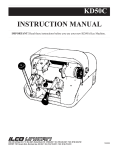
The Waste Water Dumping System uses a device called a Macerator to expel the fluid from the tanks.
Macerator Pumps are very compact and lend themselves to installations short on space. Matter to be discharged
passes through a bronze cutter which reduces the waste particle size, and is then pumped by the flexible
impeller pump, discharging through a 1" (25mm) hose. The macerator cutter will usually not handle rags, hard
objects, sanitary napkins, etc.
•
•
•
Macerator pumps break up solids, which minimizes clogging. They can, also, be used to pump into a
holding tank.
Less water is required for flushing with a macerator.
Macerator pumps can require up to 10 or 15 amps of power and cannot be run dry
Macerator Pumps are designed to empty your holding tanks when fitted onto the plumbing in recreational
vehicles (and boats). The function of the pump is to suction the solids and liquids from the lines connected to
the holding tanks and grind the effluent with the rotating cutter head down to a small particle size for simple
discharge of the waste. Eliminating gravity as a method to empty the tanks allows the user to lift the waste to a
convenient receptacle either above or below the pump elevation.
Electric pumps can pump the waste from holding tanks and certain types of toilets. The term “macerator” refers
to the action of the pump that grinds the waste as it enters the inlet of the pump. Most Macerator Pumps are
self-priming, which means the pump will lift the waste solids and liquids up to the inlet of the pump and then
lift the discharge above the pump to empty into holding tanks. Macerator Pumps help prevent clogged lines due
to the function of grinding up the waste and smaller discharge lines are permissible once the solids are
macerated.
Typically, Macerator Pumps are not designed to be run dry of liquids. The impellers will wear and the pump’s
capacity to discharge the liquids will be lessened. The most advanced designed Macerator Pumps will
automatically shut off if the pump runs dry of liquids. This Roadtrek model does not have an Automatic Shutoff.) The run dry protection is not designed to be used as a means to automatically shut off the pump. The 20second delay will, in fact, cause wear to the impeller of the pump.
Page 1 of 26 Table of Contents
A. ‐ FRESH WATER SYSTEM: .................................................................................................................................................... 3
1. ‐ FRESH WATER TANK GRAVITY FILL: .............................................................................................................................. 4
a) ‐ FILLING THE INTERIOR FRESH WATER TANK: ............................................................................................................ 4
b) ‐ FILLING THE EXTERIOR FRESH WATER TANK: ........................................................................................................... 5
2. ‐ FILLING WATER TANKS WITH EXTERIOR CITY WATER CONNECTION: .......................................................................... 6
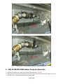
3. ‐ USE OF WATER PUMP (Water Tanks Are Now Full): ..................................................................................................... 8
4. ‐ SANITIZING: ................................................................................................................................................................... 9
a) ‐ TO SANITIZE THE FRESH WATER SYSTEM: ................................................................................................................ 9
5. ‐ CITY WATER CONNECTION:........................................................................................................................................... 9
6. ‐ OUTSIDE SHOWER: ..................................................................................................................................................... 10
7. ‐ DRAINING: ................................................................................................................................................................... 10
a) ‐ TO COMPLETELY DRAIN THE FRESH WATER SYSTEM OF ALL WATER: ................................................................... 10
8. ‐ “SUMMER USE”: ......................................................................................................................................................... 12
a. ‐ “SUMMER USE” VALVE POSITION: .......................................................................................................................... 12
9. ‐ “WINTER USE”: (Moderate Subfreezing Conditions, ‐10°C (14°F)): ............................................................................ 13
a) ‐ USE DURING WINTER: ............................................................................................................................................. 13
10. ‐ WATER SYSTEM WINTERIZING (for Storage): ........................................................................................................... 18
a) ‐ TO COMPLETELY WINTERIZE YOUR FRESH WATER SYSTEM: .................................................................................. 18
b) ‐ DE‐WINTERIZE: ....................................................................................................................................................... 19
B. ‐ WASTE WATER SYSTEM: ................................................................................................................................................. 19
1. ‐ WASTE WATER TANK PREPARATION: ......................................................................................................................... 19
2. ‐ WASTE WATER TANK DUMPING: ................................................................................................................................ 22
a) ‐ TO DUMP THE BLACK WASTE WATER TANK: .......................................................................................................... 22
b) ‐ TO DUMP THE GREY WASTE WATER TANK: ........................................................................................................... 22
3. ‐ WASTE WATER TANK FLUSHING: ................................................................................................................................ 22
a) ‐ TO FLUSH THE WASTE WATER TANKS: ................................................................................................................... 22
FRESH WATER SYSTEM SCHEMATIC ...................................................................................................................................... 23
WASTE WATER SYSTEM SCHEMATIC .................................................................................................................................... 24
WINTERIZING THE SURBURBAN WATER HEATER MODEL SW6D ......................................................................................... 25
DRAINING AND STORAGE INSTRUCTIONS: ....................................................................................................................... 25
RV ANTIFREEZE ...................................................................................................................................................................... 26
Propylene glycol ................................................................................................................................................................ 26
From Prestone Products Corporation: .............................................................................................................................. 26
Page 2 of 26 A. - FRESH WATER SYSTEM:
The Fresh Water System consists of two Holding Tanks. One tank is located in the vehicle’s interior; the other
tank is located on the vehicle’s exterior. The purpose of the dual tank system is to provide a fresh water system
that can be used in during moderate sub freezing conditions. The system, therefore, can function in either one of
two modes -- I will call them, for the sake of simplicity, “Summer Use” or “Winter Use.”
Furthermore, this Roadtrek model is equipped with a water system that can be either completely self contained
or fully dependent on an outside source of water. If using an outside source of water it is important to keep in
mind that the System is NOT equipped with a pressure regulator to compensate for varying water pressure
levels.
During self contained use, caution should be taken so as to minimize water consumption. Water consumption,
for example, can be reduced while showering if you turn off the shower between wetting down and rinsing off.
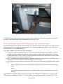
To avoid damage due to road vibrations, be sure not to store heavy or sharp objects where they may come into
contact with either the water lines or water pump – those compartments marked: “THIS IS NOT A
STORAGE COMPARTMENT”. Additionally, you should allow sufficient room around the pump for
proper operation.
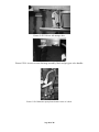
Picture W-1: Water Supply Cabinet
Page 3 of 26 1. - FRESH WATER TANK GRAVITY FILL:
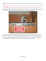
Fresh water tanks can be filled individually using the gravity fills located at the driver side entry door
and the passenger side rear door. Both tanks can also be filled using the rear fill if the interior tank drain
valve (Picture W-2) located beside the water pump is open. (open is aligned with water line)
Picture W-2: Interior tank drain valve in closed position.
a) - FILLING THE INTERIOR FRESH WATER TANK:
The Interior Fresh Water Tank can be filled through the gravity fill located in the passenger-side rear door
opening (see Picture W-3). To fill the interior tank:
1. Open the rear passenger door.
2. Open the gravity fill cover by removing the orange plug, (see Picture W-3).
3. Insert the hose and fill the tank using moderate pressure, (excessive pressure will result in a back
flow of water).
4. When the tank is full, water will overflow back through the gravity fill hole.
5. Overfilled tanks will spill out through tank vents. This is evidenced by water dripping from the rear
passenger side corner of van.
Page 4 of 26 Picture W-3 : The gravity fill for the interior fresh water tank, (located on passenger-side rear door post).
b) - FILLING THE EXTERIOR FRESH WATER TANK:
The Exterior Fresh Water Tank can be filled through the gravity fill located the Driver-side front door opening
(see Picture W-4). To fill the interior tank:
1. Open the front driver side door.
2. Open the gravity fill cover by removing the orange plug, (see Picture WS-4).
3. Insert the hose and fill the tank using moderate pressure, (excessive pressure will result in a back
flow of water).
4. When the tank is full, water will overflow back through the gravity fill hole.
5. Overfilled tanks will spill out through tank vents. This is evidenced by water dripping from the
underside of the van.
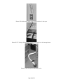
Page 5 of 26 Picture W-4: The water fill for the external fresh water tank, (located at driver-side front door post).
2. - FILLING WATER TANKS WITH EXTERIOR CITY WATER CONNECTION:
The fresh water tanks can also be filled through the City Water Inlet located behind the rear lockable driver side
access drawer. The use of the city fill is not possible when in the “Winter Use” mode.
NOTE: Prior to using city fill, ensure water system is in “Summer Use” mode.
Both fresh water tanks can be filled from the city water connection. You have the option to fill both tanks
together or separately depending on the position of the inside valves.
To fill the tank:
1. Connect City Water Hose and open adjacent City Water Valve (Picture W-10). Remove the Orange
Gravity-fill Plug for added venting of the Fresh Water Tanks.W-7).
2. Open the water source moderately.
3. When the tank is full, water will overflow in the same manner as when using the gravity fill..
4. Interior Tank Drain Valve in open position (Picture W-1) will fill both tanks. (open is aligned with water
line)
5. If the Interior Tank Drain Valve is closed (Picture W-1), the tanks can be filled separately. The tank
selector valve (the one with the red handle) will allow this separate tank filling -- valve in down position
will fill the Exterior (Lower) Tank, valve in up position will fill the Interior (Upper) Tank.
6. Shut off City Water Hose and close the City Water Tank-fill Shut-off Valve (see Picture W-8).
Page 6 of 26 Picture W‐5: Hookup Compartment.
Picture W‐6: Location of the city water inlet connection.
Page 7 of 26 Picture W-7: Open position of the city water tank fill valve.
Picture W-8: Closed position of the city water tank fill valve.
3. - USE OF WATER PUMP (Water Tanks Are Now Full):
1. External city water valve must be in down (closed) position. {Picture}
2. With selector valve in down position, water is drawn from the External (Lower) Tank; valve in up
position, water is drawn from the Interior (Upper) tank.
Page 8 of 26 3. The Interior Tank Drain Valve, if open (Picture G-P7), will allow the use of both tanks by pumping
water from the Lower and the Upper Tank, then draining into the Lower Tank. Keep the Selector Valve
in the down position for this function.
4. - SANITIZING:
NOTE: To properly sanitize the water the system must be in “Summer Use” mode.
Your Fresh Water System should be sanitized if it is new, has not been used for a period of time, or may have
become contaminated.
a) - TO SANITIZE THE FRESH WATER SYSTEM:
1. Prepare a chlorine solution using 4 L, (1 gallon) of water and 60 ml, (1/4 cup) of household bleach, (5%
sodium hypo chlorite solution).
2. With the fresh water tank empty, (see section on Waste Water Tank Flushing), pour, (see section on
Filling Fresh Water Tank) 4 L, (1 gallon) of solution into the fresh water tank for each 60 L (15 gallon)
of tank capacity. As an alternative, several commercial solutions are available and should be used as
directed on the package.
3. Complete filling of the tank with fresh water.
4. Turn on the water pump and slowly open all faucet's to release trapped air.
5. Close faucet's and allow to stand for 3 hours then drain and flush with fresh potable water.
6. To remove excessive chlorine taste or odor which may remain, prepare a solution of 1 L, (1 quart)
vinegar to 20 L, (5 gallons) water and pour into tank and allow solution to agitate in tank by vehicle
motion, (several days if possible).
7. Drain tank and flush with fresh potable water.
5. - CITY WATER CONNECTION:
NOTE: City water connection can only be used in summer operation mode.
The city water inlet connection is located inside the smaller driver-side storage compartment, (see Picture GP10).
To connect the water system to an outside source:
1.
2.
3.
4.
Ensure that the water pump is turned off.
Close the city water tank fill valve by turning the handle to the vertical position, (see Picture G-P12).
Be sure that all interior faucet's are closed to prevent spillage.
Open the city water source slowly to prevent excessive water force inside your vehicle. To protect your
system from excessive pressure from water supply systems encountered in some areas, a water
pressure regulator should be used. Such a regulator is not supplied with your vehicle.
5. Note that this connection by-passes the Water Pump and Fresh Water Tank. Therefore, the use of these
items is not necessary when connected directly to an external water source.
To disconnect the city water connection:
1. Turn off the external water source.
2. Open the sink faucet to relieve the pressure in the system, (failure to do so may result in an unexpected
shower).
3. Ensure that the City Water Tank Fill Valve is closed, (see Picture G-P12).
4. Remove the hose from the City Water Connection; replace the cap on fill connection.
Page 9 of 26 6. - OUTSIDE SHOWER:
NOTE: Outside shower can only be used in “Summer Use” mode.
The outside shower faucet is found in the outside storage compartment at the driver-side rear. Remove the
shower hose from the storage compartment and attach to the faucet spout, (see Picture W-9).The shower hose
must be returned to the storage compartment before travel as to prevent damage to the unit.
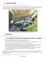
Picture W-9: Outside shower and shore power connection.
7. - DRAINING:
NOTE: Water system must be in “Summer Use” mode.
a) - TO COMPLETELY DRAIN THE FRESH WATER SYSTEM OF ALL WATER:
1. Ensure that the Water Pump is off and that your vehicle is level.
2. Ensure that the Interior Tank Valve is in the open position. {Picture}
3. Drain the Fresh Water Tank and the hot and cold Fresh Water System by opening the Exterior Fresh
Water Drain Valve at the low point drain, (see Picture G-P5 on page G-3).
4. Open all water outlets including the sink faucet, Interior shower faucet, external shower faucet, and
toilet by flushing pedal. The latter can be propped open or opened manually several times. This
procedure allows gravity to draw any remaining water out through the tank drains.
5. Your vehicle is equipped with a water heater. Follow the manufacturer’s instructions for draining.
6. Open the sink faucet and turn on the water pump until water is no longer pumped.
7. Turn off the water pump.
If this procedure is followed, it is unnecessary to blow out the water system. In fact, Roadtrek specifically
cautions against using compressed air to blow out the water lines. Once the system is drained, be sure to close
all taps before driving.
NOTE: Do not allow water to remain in tanks when vehicle is not in use.
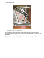
Page 10 of 26 Picture W-10a: Interior Tank Valve in Open Position
Picture W-10b: Exterior Fresh Water Drain Valve in Open position (Correct Image)
Page 11 of 26 8. - “SUMMER USE”:
Picture W-11a: Water Pump Compartment
a. - “SUMMER USE” VALVE POSITION:
1. The dual tank system requires you to switch from the Interior Tank to the Exterior Tank position
(Down) for “Summer Use”(see Picture W-11b). This lets you utilize the full capacity of both fresh water
holding tanks.
2. To utilize the Interior Tank and the Exterior Tank at the same time, you must open the Interior Fresh
Water Tank Drain and position the Supply Selector Valve to the exterior or “Summer Use” position
(Down), (see Picture W-12).
Page 12 of 26 Picture W-11b: Selector Valve position for supply from the Exterior Fresh Water Tank.
Picture G-12: Interior tank drain valve in open position.
9. - “WINTER USE”: (Moderate Subfreezing Conditions, -10°C (14°F)):
The dual tank system allows you to use the Fresh Water System under moderate subfreezing conditions by
allowing you to isolate and drain the Exterior Fresh Water Tank.
Before starting the “Winter Use” mode instructions, you must first winterize the complete water system by
following the “Water System Winterizing (for Storage)” instructions. You will, then, flush the antifreeze out of
the Interior or “Winter Use” system. Only then can you safely use your Motor Home in “Winter Use” mode.
a) - USE DURING WINTER:
•
•
Use only gravity fill for interior water tank.
No outdoor shower.
Page 13 of 26 •
•
•
•
Waste water tanks are unprotected from freezing unless charged with antifreeze.
Interior temp must be maintained above 65°F(18°C).
Refrigerator must be turned ON.
Exterior fresh tank must be drained.
To drain the City Fill hose in front of the City Water Tank Fill Valve, depress the center of the check valve
(Picture G-P0) with a finger or other blunt object to release the pressure and drain the water or antifreeze.
To prepare your Motor Home’s Fresh Water System for “Winter Use” you must do the following:
1. Ensure that the Water Pump is turned off (switch is found on the monitor panel) before isolating and
draining the exterior fresh water tank.
2. Switch Tank Selector Valve to Interior Tank position, (see Picture W-13).
3. Drain Exterior Fresh Water Tank by opening Exterior Drain Valve, (see Picture W-14).
Note: During “Winter Use,” the Waste Water System also needs to be “Winterized.” Run RV antifreeze through
the macerator and out through the hose to ensure they are protected.
Picture W-13: Selector valve position for supply from the interior fresh water tank.
Page 14 of 26 Picture W-14: Exterior fresh water tank low point drain valve.
To drain the exterior fresh water tank you must open exterior drain valve at the low point drain located below
the driver’s side front storage drawer compartment, (see Picture W-14).
NOTE: The Water Heater should be drained and should not be used in sub-freezing weather.
Roadtrek Motorhomes Inc. does not recommend the use of the Water Heater in the “Winter Use” mode because,
if it is allowed to freeze (maybe run out of propane, etc.) it will expand and break. This is a very costly repair
and the unit can be very difficult to replace.
If you wish to chance it, however, take these precautions:
a) Do not drive with your propane turned on. This can be extremely dangerous if you happen to be in an
accident. Also the venting of the appliance systems could blow out the flame during transit. Although
the water heater has a "retry" circuit, it will go into lockout after three tries after which it will not restart
until the manual switch is turned off and back on.
b) Ensure all outside water lines have antifreeze in them so they do not freeze. Do not get antifreeze in the
water heater (I.E bypass it before introducing antifreeze to the system).
c) If you plan to use your water heater make sure that you have the water heater full and the propane turned
on.
However, before you leave or put your unit in transit; decide if you will need to drain the water
heater
and/or
if you will be stopping, determine if you will then be able to fire up the water heater to prevent
freezing?
Your Roadtrek is equipped with a Water Heater By-pass Valve. When it is in “Summer Use” mode (or if the
Water Heater is used during “Winter Use” mode), all three valves will face the aisle, (see Picture W-17). In
Page 15 of 26 Storage (Winter) mode, the By-pass Valve is open and the valves at the Water Heater are closed, (see Picture
W-18).
NOTE: When the water system is operating in the “Winter Use” mode, only the interior fresh water tank is to
be used.
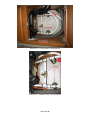
The two unmarked valves in the floor of the compartment (forward of the Sub-Woofer compartment) are the
exterior shower/city fill isolator valves (Picture W-15). These valves are used to protect the exterior shower and
the city fill from freeze damage during “Winter Use” mode. See Water System Illustration.
Picture W-15: Exterior Shower Isolation valves in closed position)
The valves should be open when introducing antifreeze and then closed if you are going to utilize the unit in
“Winter Use” mode. If you are winterizing and then subsequently store the unit, you can leave these open.
To prevent interior lines from freezing when vehicle is in “Winter Use” mode, it is recommended that the
interior temperature be maintain at or above 18ºC (65ºF) and the refrigerator left running.
Page 16 of 26 Picture W-16: Water Heater Compartment
Picture W-17: Summer mode valve positions.
Page 17 of 26 Picture W-18: Storage (Winter) mode valve positions.
10. - WATER SYSTEM WINTERIZING (for Storage):
NOTE:Water system must be in “Summer Use” mode and then repeat operations 5 and 6 with water system in
“Winter Use” mode.
a) - TO COMPLETELY WINTERIZE YOUR FRESH WATER SYSTEM:
1. Drain the entire system including water heater, (refer to water heater manual for instructions on
draining). (See Appendix)
2. Water heater by-pass: Your Roadtrek is equipped with a water heater by-pass valve. When it is in “Summer Use” mode, all
three valves will face the aisle, (see Picture W-17). In “Winter Use” mode, the water line valve is open
and the valves at the water heater are closed, (see Picture W-18).
Note: Never allow antifreeze into the water heater.
3. Add 8 L, (2 gallons) of approved nontoxic recreational vehicle antifreeze to the Interior and Exterior
Fresh Water Tanks using both Gravity Fills. Note: Use only plumber’s or RV antifreeze. 4.
5.
6.
7.
Turn on the water pump.
Open all three faucets (Galley, Interior Shower, and External Shower) until antifreeze is visible.
Open the toilet valve until antifreeze is visible.
Open the City Fill valve (See picture W-7) for several seconds to let antifreeze through this portion of
water lines. Then close valve again.
8. Turn off Water Pump.
9. Remove the plug (both?) for the Interior shower drain and fill P-Trap with antifreeze.
10. Release pressure from City Water Inlet by pushing on the center plunger of the Water Connector (See
Picture W-19).
Page 18 of 26 11. Run RV antifreeze through the macerator and out through the hose to ensure it is winterized.
Picture W-19: City water fill check valve.
b) - DE-WINTERIZE:
1. Drain antifreeze from the system.
2. Sanitize the system if desired.
3. Fill the system with water.
B. - WASTE WATER SYSTEM:
This vehicle is equipped with a waste water storage and dumping system that will provide adequate and
effective storage and dumping of waste water. Your vehicle should be as level as possible to allow optimal
operation of the system.
CAUTION: Ensure that both the black and grey water gate valves are closed, (inward position) before using
the waste water system. This applies especially after extensive driving. Black and grey water
dump valves are accessed through the driver side storage door, (see Picture G-P13).
1. - WASTE WATER TANK PREPARATION:
This vehicle is equipped with two waste water tanks; the grey waste water tank is for waste water from the sink
and Interior shower. The black waste water tank is for sewage from the toilet. Both tanks are equipped with
separate dump valves so that each may be dumped independently.
CAUTION: During “Winter Use” mode under moderate subfreezing conditions, (refer to page G.1-G.3)
antifreeze is required in the exterior black and grey waste water tank.
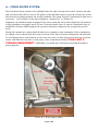
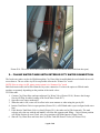
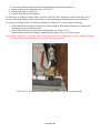
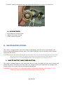
Page 19 of 26 Picture G-P13: Driver side storage door.
Picture G-P14: Access to sewer discharge assembly, black and grey gate valve handles.
Picture G-P15:Macerator pump located under center of vehicle.
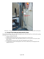
Page 20 of 26 Picture G-P16:Macerator pump switch located on driver’s door post.
Picture G-P17: Sewage discharge hose storage located in driver’s side storage drawer.
Picture G-P18: Sewage hose discharge valve.
Page 21 of 26 2. - WASTE WATER TANK DUMPING:
a) - TO DUMP THE BLACK WASTE WATER TANK:
1. Turn the battery disconnect switch to the “ON”position, if not already on, (located on the monitor
panel).
2. Remove sewage discharge hose from storage, (see Picture G-P17).
3. Insert the discharge outlet into the waste receptacle.
4. Open the valve on the sewage hose, (see Picture G-P18) (NOTE: valve closed in picture).
5. Open the black water tank valve, (see Picture G-P14).
6. Open the driver’s door, press and hold the macerator pump switch until the tank is empty, (see Picture
G-P16).
b) - TO DUMP THE GREY WASTE WATER TANK:
1. Open grey water tank valve. (It is recommended to always dump the black water tank first and then the
grey water tank.)
2. Repeat step 6.
3. Close all valves.
4. Return sewage hose to its storage compartment.
5. Turn battery disconnect to the “OFF” position.
NOTE: Do not operate the macerator pump "dry".
NOTE: If macerator should get clogged you will have to push and turn the manual macerator crank "T" handle
to dislodge any debris that might be blocking the macerator, (see picture G-P15).
3. - WASTE WATER TANK FLUSHING:
a) - TO FLUSH THE WASTE WATER TANKS:
1. Ensure that both tanks are empty by checking the monitor panel.
2. Fill the black waste water tank by inserting a hose into the toilet, (be sure to step on the flush pedal, so
the flapper door stays open to prevent toilet overflow) and fill the grey waste water tank using the
sink.
3. Dump both tanks using the procedure outlined above.
Both waste water tanks can also be flushed using a similar procedure, but rather than filling each tank using the
Fresh Water System, they can be filled by inserting a hose directly into the sink and toilet.
Page 22 of 26 FRESH WATER SYSTEM SCHEMATIC
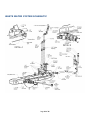
Page 23 of 26 WASTE WATER SYSTEM SCHEMATIC
Page 24 of 26 WINTERIZING THE SURBURBAN WATER HEATER MODEL SW6D
DRAINING AND STORAGE INSTRUCTIONS:
If RV is to be stored during Winter months, the Water Heater must be drained to prevent damage from freezing.
1.
2.
3.
4.
5.
6.
Turn off electrical power to Water Heater either at the switch from the electrical element or at Breaker.
Shut off gas supply to Water Heater.
Turn off Pressure Pump on Water System.
Open both Hot and Cold Water Faucets.
Remove Anode Rod from tank.
Follow RV Manufacturer’s instructions for draining entire Water System.
NOTE: Be certain to refill Water Heater with water and remove all air from tank and lines before re-lighting or
before turning on electrical power.
If your Water Heater Plumbing System is equipped with a by-pass kit, use it to close off the Water Heater, drain
the Water Heater completely, and leave the Water Heater closed off (out of the system) in the by-pass position –
particularly if you are introducing antifreeze in to the plumbing system. Antifreeze can be very corrosive to the
Anode Rod creating premature failure and heavy sediment in the tank. If the plumbing system is not equipped
with a by-pass kit, and you intend to Winterize by adding antifreeze to the system, remove the Anode Rod
(storing it for the Winter) and replace it with a ¾” drain plug.
WARNING! Hydrogen gas may result if you have not used this heater for two weeks or more.
HYDROGEN GAS IS EXTREMELY FLAMMABLE. To reduce the risk of injury under these
conditions, open the hot water faucet for several minutes at the kitchen sink before you use any electrical
appliance connected to the hot water system. If hydrogen is present, you probably will hear an unusual
sound such as air escaping through the pipe as the water begins to flow.
Hydrogen gas may be present even after water has been drained from the tank. Open faucet at sink and
allow system to vent for several minutes (5-10 minutes).
Do not smoke or have any open flame near the open faucet. Do not attempt to light pilot or main burner.
On DSI models, be sure the switch is “OFF”.
Page 25 of 26 RV ANTIFREEZE
Propylene glycol
Propylene glycol, on the other hand, is considerably less toxic and may be labeled as "non-toxic antifreeze". It is
used as antifreeze where ethylene glycol would be inappropriate, such as in food-processing systems or in water
pipes in homes, as well as numerous other settings. It is also used in food, medicines, and cosmetics, often as a
binding agent. Propylene glycol is "generally recognized as safe" by the Food and Drug Administration (FDA)
for use in food. However, propylene glycol-based antifreeze should not be considered safe for consumption. In
the event of accidental ingestion, emergency medical services should be contacted immediately.
Propylene Glycol oxidizes when exposed to air and heat. When this occurs, organic acids are formed – Glycolic
acid, Glyoxalic acid, Formic acid, Carbonic acid & Oxalic acid. If not properly inhibited, this fluid can be very
corrosive. Protodin is added to Propylene Glycol to act as a buffer, preventing low pH attack on the system
metals. It forms a protective skin inside the tank and pipelines which helps to prevent acid attack that cause
corrosion.
Beside cooling system breakdown, biological fouling also occurs. Once bacterial slime starts the corrosion rate
of the system increases. In system where a glycol solution is maintained on a continuous basis, regular
monitoring of freeze protection, pH, specific gravity, inhibitor level, color and biological contamination should
be checked on routine basis.
Propylene glycol should be replaced when it turns reddish in color.
From Prestone Products Corporation:
“RV Waterline Antifreeze” is ideal for winterizing all types of potable water supply systems. Recommended for
use in boats, trailers, recreational vehicles, vacation homes, swimming pool filtration and heating systems.
Unsurpassed rust and metal protection for all metal pipes commonly found in water supply systems.
To Winterize Systems Generally:
1. Turn off fresh water supply.
2. Completely drain water lines at all outlets thoroughly following manufacturer’s directions.
3. Refill systems to capacity with undiluted Prestone RV Antifreeze.
4. Re-pressurize water supply system.
5. Open all hot and cold faucets one at a time to see if system is full. Pink color confirms system is full.
To De-Winterize Systems:
1. Open all hot and cold faucets and run fresh water through system until all color disappears.
2. Flush several times until all color disappears.
3. Fill fresh water supply tank.
Page 26 of 26