1
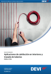
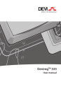
MAKING MODERN LIVING POSSIBLE
Danfoss Air
User manual for Danfoss
Air a2, a3, w1 and w2
DANFOSS HEATING
Contents
1.0 System overview . . . . . . . . . . . . . . . . . . . . . . . . . . . . . . . . . . . . . . . . . . . 4
2.0 Main functions
2.1 Away . . . . . . . . . . . . . . . . . . . . . . . . . . . . . . . . . . . . . . . . . . . . . 5
2.2 Bypass . . . . . . . . . . . . . . . . . . . . . . . . . . . . . . . . . . . . . . . . . . . . 5
2.3 Info . . . . . . . . . . . . . . . . . . . . . . . . . . . . . . . . . . . . . . . . . . . . . . 5
2.4 Boost . . . . . . . . . . . . . . . . . . . . . . . . . . . . . . . . . . . . . . . . . . . . . 6
2.5 Operating mode . . . . . . . . . . . . . . . . . . . . . . . . . . . . . . . . . . . . . . 6
2.6 Menu structure . . . . . . . . . . . . . . . . . . . . . . . . . . . . . . . . . . . . . . 8
2.7 Settings . . . . . . . . . . . . . . . . . . . . . . . . . . . . . . . . . . . . . . . . . . 10
3.0 Maintenance
3.1 Replacing filters . . . . . . . . . . . . . . . . . . . . . . . . . . . . . . . . . . . . . 14
3.2 Replacing Air Dial batteries . . . . . . . . . . . . . . . . . . . . . . . . . . . . . . 15
3.3 Cleaning the unit . . . . . . . . . . . . . . . . . . . . . . . . . . . . . . . . . . . . 15
4.0 Options
4.1 Replacement filters . . . . . . . . . . . . . . . . . . . . . . . . . . . . . . . . . . . 17
4.2 Controlling the system by PC . . . . . . . . . . . . . . . . . . . . . . . . . . . . . 17
4.3 Heat surfaces . . . . . . . . . . . . . . . . . . . . . . . . . . . . . . . . . . . . . . . 18
5.0 Troubleshooting . . . . . . . . . . . . . . . . . . . . . . . . . . . . . . . . . . . . . . . . . . 21
2
DANFOSS AIR
Thank You for Buying a Danfoss Product
GB
Air unit a3
Air unit w2
All Danfoss Air units are
Passive House certified by
The Passive House Institute
in Darmstadt
CCM module
Air Dial
The Danfoss Air system uses Z-Wave wireless technology. Find more information on our
website www.air.danfoss.com on the possibilities with Danfoss Air and Z-Wave technology.
DANFOSS HEATING
3
1.0 System overview
Congratulations on purchasing Danfoss Air, one of the most
advanced, efficient and quiet ventilation systems with heat
recovery on the market.
On the following pages, we will take you through the steps
needed to operate your system successfully as well as show
you the few steps needed to maintain the system.
The operation of your system is all collected in one control
panel, the Danfoss Air Dial. You have the entire system under
control by rolling and pushing the dial, whilst the necessary
information is shown in the display.
Danfoss Air unit
Wireless Air Dial
Power
supply
4
CCM
DANFOSS AIR
2.0 Main functions
2.1
Away
rste rækker
erste rækker
erste rækker
PROG
%
“Away icon”
Main menu > Away
Use this command when you leave your house for a prolonged period of time. The Away command reduces the
air volume in the system to an absolute minimum, inside a
defined interval. The unit will automatically assume normal
operation when the away period is over.
Note: If a heating surface is installed (optional), it is turned
%
PROG
off during the away mode (for financial
reasons).
GB
2.2
Bypass
derste
rækker
(not available
on w1 units)
“Bypass icon”
Main menu > Bypass
The bypass function is a cooling function which opens a
passage parallel to the heat exchanger. This stops the heat
exchange process. When the bypass is open, outdoor air is
led directly into the house. The bypass can be activated in
two ways:
1. Manually, by pressing the bypass command. This will
start the bypass function for 3 hours (the run time can
be changed in the settings menu). The bypass will not
activate if the outdoor temperature is lower than +5°C.
2. Automatically if the outdoor air and room temperature
are above the selected level. In the Settings menu
you can set the temperatures at which the system is to
activate an automatic bypass. The bypass automatically
closes again when one of the two temperatures is lower
than required.
2.3
Info
DANFOSS HEATING
Main menu > Info
The info command shows a list, showing the present status
of your unit. Here you can see all measured temperatures,
fan steps, relative humidity in the room, and much more...
5
2.0 Main functions
2.4
Boost
Main menu > Boost
The boost command can be used in situations where you
require a higher air volume than normal. Use it if you are
having a party, if you are cooking something with a strong
odour, if someone is smoking, etc. The boost function is
timer-based, and as default runs for 3 hours (boost duration
can be changed in the Settings menu). In boost the unit
runs at 100% speed.
If it is not required that the system run at maximum capacity with boost, the maximum boost step can be set in the
Settings > Boost > Max. menu. Boost step. In this menu you
can also switch the Autoboost function on or off.
Autoboost is a function which automatically increases air flow
if sudden humidity arises (bathing activity or cooking) - the
function is active for an hour after activation after which the
system returns to the original air flow.
2.5
Mode
rækker
e rækker
6
Main menu > Mode
With the Mode command you can change how the ventilation system is controlled. Each Mode has its unique traits
- choose the one that suits you the best:
Mode > Manual
In manual mode the air volume is kept
constantly at the level
% you have selected
PROG
(fan step 1 to 10). The control of the bypass
“Manual icon” function (see 2.2) is usually automatic, but
if you do not require this, the automatic
bypass function can be switched off in: Settings > Bypass >
Automatic bypass: On/Off.
It is also possible to switch the Autoboost (see 2.4) on/off so
that the system runs constant air volume normally and only
increases the air volume if significant moisture develops in
the house (during a bath or cooking).
Control of the Autoboost function is usually automatic, but
if you do not require this, the Autoboost function can be
deactivated in: Settings > Boost > Autoboost: On/Off
DANFOSS AIR
2.0 Main functions
PROG
Mode > Demand
In the demand mode the built-in humidity sensor ensures that the air volume is
%
regulated. At low outdoor temperatures at
which the relative air humidity in the house
“Demand icon” becomes too low (=”too dry”), the system
reduces the air volume automatically. At
those times of year when it can become too humid indoors,
the system will work with a higher air change. This takes
place automatically according to the season - the user does
not have to worry about anything.
GB
Note: Outside the heating season, when the outdoor air
contains more moisture than in the winter period, the air
flow will remain more or less constant, at a rate equivalent
to the set basic step - this ensures maximum comfort in the
part of the season where heat loss is negligible.
Mode > Programme
In program mode a pre-defined family
% is chosen. Based on the profile,
PROG
profile
”Programme icon” ventilation rate is high during the
periods when the house is occupied and
less when the house is empty. Periods of higher air change
have also been included for when baths are taken or cooking takes place.
If none of the five pre-defined family profiles suits your
requirements, you can download (as freeware) a pc-tool that
includes the option of creating your own user profile. See
installation manual for more info, or go to www.air.danfoss.
com.
r
er
The default profile is no. 1 so this profile is active if you
choose ”program mode”.
DANFOSS HEATING
7
2.0 Main functions
2.6
Menu structure
Main menu
Back
Boost
Away
Bypass
Info
Mode
Settings
On / Off
On / Off
On / Off
Activates manual boost for a limited time
Reduces air volume to an absolute minimum inside a defined inter
Activates manual bypass for a limited time
Back
Program
Bypass
Boost
Time & Date
Night cooling
Restore defaults
Set
On / Off
B
Back
Factory settings:
No
Yes
Note: w1 systems are not equipped with the bypass function. Bypass-related menu items are
therefore not visible when operating a w1 system.
8
DANFOSS AIR
M
2.0 Main functions
GB
rval
Back
Back
Back
Back
Back
Boost duration:
3 hours
Auto boost:
On / Off
Max. boost step:
10 / 10
Bypass
(if room temp.):
>22°C
and
Profile 1
Profile 2
Profile 3
Profile 4
Profile 5
Demand
Program
Manual
Actual step
Humidity
Filter remain
Temperatures
Accessories
Show runtime
Basic step
Alarm status
Alarm log
SW & unit ID
Outdoor air:
>16°C
Bypass duration:
3 hours
Auto bypass:
On / Off
DANFOSS HEATING
9
2.0 Main functions
2.7
Settings
Main menu > Settings
In the settings menu, you can access a range of default
settings, and thus customise the system to your demands.
Here are the settings that can be changed, and a short
description of the effect changing the setting has:
Main menu > Settings > Weekly programme > Choose
profile 1-5
Tell the system what kind of family you have, and it will react
accordingly.
Profile 1: Family with children, both adults working normal
working hours.
Fan
(% of basis step)
Profile P1 – Weekdays
120
100
80
60
40
20
00:00
01:00
02:00
03:00
04:00
05:00
06:00
07:00
08:00
09:00
10:00
11:00
12:00
13:00
14:00
15:00
16:00
17:00
18:00
19:00
20:00
21:00
22:00
23:00
24:00
0
Fan
(% of basis step)
Profile P1 – Weekends
120
100
80
60
40
20
00:00
01:00
02:00
03:00
04:00
05:00
06:00
07:00
08:00
09:00
10:00
11:00
12:00
13:00
14:00
15:00
16:00
17:00
18:00
19:00
20:00
21:00
22:00
23:00
24:00
0
Profile 2: Family with children, one working adult, normal
working hours, one adult at home during the day.
Fan
(% of basis step)
Profile P2 – Weekdays
120
100
80
60
40
20
00:00
01:00
02:00
03:00
04:00
05:00
06:00
07:00
08:00
09:00
10:00
11:00
12:00
13:00
14:00
15:00
16:00
17:00
18:00
19:00
20:00
21:00
22:00
23:00
24:00
0
Fan
(% of basis step)
Profile P2 – Weekends
120
100
80
60
DANFOSS AIR
40
20
0
:00
:00
:00
:00
:00
:00
:00
:00
:00
:00
:00
:00
:00
:00
:00
:00
:00
:00
:00
:00
:00
:00
:00
:00
:00
10
DANFOSS HEATING
0:00
1:00
2:00
3:00
4:00
5:00
6:00
7:00
8:00
9:00
0:00
1:00
2:00
3:00
4:00
5:00
6:00
7:00
8:00
9:00
0:00
1:00
2:00
3:00
4:00
00:00
01:00
02:00
03:00
04:00
05:00
06:00
07:00
08:00
09:00
10:00
11:00
12:00
13:00
14:00
15:00
16:00
17:00
18:00
19:00
20:00
21:00
22:00
23:00
24:00
00:00
01:00
02:00
03:00
04:00
05:00
06:00
07:00
08:00
09:00
10:00
11:00
12:00
13:00
14:00
15:00
16:00
17:00
18:00
19:00
20:00
21:00
22:00
23:00
24:00
00:00
01:00
02:00
03:00
04:00
05:00
06:00
07:00
08:00
09:00
10:00
11:00
12:00
13:00
14:00
15:00
16:00
17:00
18:00
19:00
20:00
21:00
22:00
23:00
24:00
00:00
01:00
02:00
03:00
04:00
05:00
06:00
07:00
08:00
09:00
10:00
11:00
12:00
13:00
14:00
15:00
16:00
17:00
18:00
19:00
20:00
21:00
22:00
23:00
24:00
2.0 Main functions
00:00
01:00
02:00
03:00
04:00
05:00
06:00
07:00
08:00
09:00
10:00
11:00
12:00
13:00
14:00
15:00
16:00
17:00
18:00
19:00
20:00
21:00
22:00
23:00
24:00
80
60
40
20
0
Fan
(% of basis step)
120
Fan
(% of basis step)
Fan
(% of basis step)
Fan
(% of basis step)
Fan
(% of basis step)
120
Profile P2 – Weekends
100
80
60
40
20
0
GB
Profile 3: Couple without children, both working adults, normal
working hours.
120
Profile P3 – Weekdays
100
80
60
40
20
0
120
Profile P3 – Weekends
100
80
60
40
20
0
Profile 4: Single person (working adult), no one at home during
work hours.
120
Profile P4 – Weekdays
100
80
60
40
20
0
Profile P4 – Weekends
100
80
60
40
11
20
0
80
60
40
20
2.0 Main functions
00:00
01:00
02:00
03:00
04:00
05:00
06:00
07:00
08:00
09:00
10:00
11:00
12:00
13:00
14:00
15:00
16:00
17:00
18:00
19:00
20:00
21:00
22:00
23:00
24:00
0
Fan
(% of basis step)
120
Profile P4 – Weekends
100
80
60
40
20
00:00
01:00
02:00
03:00
04:00
05:00
06:00
07:00
08:00
09:00
10:00
11:00
12:00
13:00
14:00
15:00
16:00
17:00
18:00
19:00
20:00
21:00
22:00
23:00
24:00
0
Profile 5: Small commercially used office or sales outlet area.
Opening times 8 am-4 pm, closed at weekends.
Fan
(% of basis step)
Profile P5 – Weekdays
120
100
80
60
40
20
00:00
01:00
02:00
03:00
04:00
05:00
06:00
07:00
08:00
09:00
10:00
11:00
12:00
13:00
14:00
15:00
16:00
17:00
18:00
19:00
20:00
21:00
22:00
23:00
24:00
0
Fan
(% of basis step)
Profile P5 – Weekends
120
100
80
60
40
20
00:00
01:00
02:00
03:00
04:00
05:00
06:00
07:00
08:00
09:00
10:00
11:00
12:00
13:00
14:00
15:00
16:00
17:00
18:00
19:00
20:00
21:00
22:00
23:00
24:00
0
Main menu > Settings > Program > Choose profile 1-5
In the event that you did not find a profile that matches
your demands, or if you simply like to experiment with the
profiles, please download the PC tool from
www.air.danfoss.com which will allow you to customize a
program to suit your demands.
If a custom programme was created using the PC-tool, it will
be visible in the menu as:
Main menu > Settings > Profile > User defined.
Main menu > Settings > Bypass
Here you can set the conditions under which the automatic
bypass damper should open. Bypass means that we use the
12
DANFOSS AIR
2.0 Main functions
outside air to cool (see 2.2 in these instructions). The bypass
function is released when the outdoor temperature exceeds
the limit you set and if the room temperature is too high. If
only one of the conditions is present, the automatic bypass
is not released.
GB
If you wish to force the bypass to open, this should be done
in the main menu. The function is active in the time period
chosen in Main menu > Settings > Bypass > Timer (default
setting is 3 hours).
Main menu > Settings > Boost
In this menu you can customise the boost function to match
your requirements. If you use the manual boost - i.e. if you
want to activate boost in the main menu - the function will
run on a timer. This timer can be set here:
Main menu > Settings > Boost > Boost duration.
In the Boost menu you can also choose whether to switch
the autoboost on or off (see Point 2.4 for an explanation
of autoboost). If autoboost is switched on, it is active in all
modes.
In certain systems, the boost function can become too powerful (the default boost setting is that the fans run up to 100 %
output). If this is the case, the maximum boost step can be
reduced here: Main menu > Settings > Max. Boost step
Main menu > settings > Time & date
Here you can adjust the time and date of your system.
Main menu > Settings > Night cooling
Here you can define whether or not you will allow night
cooling (disabled as default). Night cooling is a form of
automatic bypass, that can be used in the summertime.
The system automatically detects if it was a warm day, and
only then will it be activated. The night cooling function
will allow the supply air to be +10 °C or higher. The function
runs from midnight until 6 am, and automatically stops if
the outdoor air is colder than +10 °C or if the extract air
temperature drops below +18 °C.
Main menu > Settings > Restore default
Restores all user settings to factory default values.
DANFOSS HEATING
13
3.0 Maintenance
3.1
Replacement
of filters
Your Danfoss Air unit was designed to assure an absolute
minimum of maintenance. Maintenance is limited to 1-2
filter replacements a year depending on the air volume and
air pollution levels in the area in which you live. In industrial
areas, and in areas with a high pollen content in the outdoor
air, the filters will be clogged faster than in a typical surburban environment.
When the unit gives the filter alarm (audible alarm from the
Air Dial + message in display)
• Go to the Air unit.
• Remove the front panel. There is no need for tools. Just lift
the panel off the unit.
•Pull out the filters and inspect
visually (if filter is only lightly
fouled/discoloured, you can
attempt to clean it, using a
vacuum cleaner equipped
with a brush. But most often
this will not be worthwhile nor
recommended).
•Fit new filters and reattach
foam covers.
If you have bought a
special pollen filter, it
should be fitted in the
filter slot to the right
(on all models) as this is
the filter that filters the
outdoor air.
•Press the filter reset button on
the front of the unit.
Observe filter replacements to get the maximum out of your
ventilation system.
Note: The fans use more power when the filters are enabled
so it is not a good idea to attempt savings here.
Standard filters and optional pollen filters (F7 class) can be
purchased from your installer.
14
DANFOSS AIR
3.0 Maintenance
3.3
Replacement of
Air Dial batteries
3.2
Cleaning
the unit
When the Air Dial needs a new
set of batteries, indicated by an
audible alarm. Lift the Air Dial
of the wall bracket, remove the
batteries and replace with new
batteries. The Air Dial uses 4 x
AAA batteries.
2
1
GB
You should clean the inside of the unit every other year.
1. Disconnect power
and remove the front
panel.
2. Unscrew the six screws
holding the three metal
rails (using the correct
size torx key).
3. Then remove the front
foam panel
4. You now have access to
the parts inside the unit.
DANFOSS HEATING
15
3.0 Maintenance
5. Pull the thick round seal
over the heat exchanger
out sideways.
6. The heat exchanger can
now be lifted/pulled
carefully out of the core.
Pour a mild soapy solution through the four open sides of
the heat exchanger (use standard washing-up liquid). Let is
soak for 5-10 minutes and then rinse under running water.
Dry of the exterior of the heat exchanger, and gently slide
the heat exchanger into the unit again.
When remounting the exchanger, the round seal should be
inserted last. This is best done by ‘locking in the two ends’
first and then pushing the rest of the seal into place.
Clean interior surfaces of the unit with a wet sponge or cloth
(use a mild soapy solution).
UNDER NO CIRCUMSTANCES use solvents to clean the foam
parts as solvents can dissolve the special foam material.
Avoid spraying water onto the main circuit board. If you do
happen to spill water onto the circuit board, tap the circuit
board lightly using a dry cloth. Leave to air dry for min. 24
hours before reconnecting the power.
Assemble the unit in reverse order:
• install the foam front panel
• secure the panel with the three metal rails
• tighten torx screws
• reinstall the front panel
You are now ready for another 2 years of troublefree service
again.
16
DANFOSS AIR
4.0 Options
4.1
Replacement
filters
Replacement filters for your Danfoss Air unit can be purchased from your installer.
The standard filters used in our units is G4 class for supply
and discharge air. A G4 filter will provide basic filtration of
particles larger than 10 μm. Use this filter for supply and
discharge air, if you do not suffer from allergy.
GB
Ordering standard filter sets (sets of two)
G4/G4 standard filter set for w1 . . . . . . . . 089F0238
G4/G4 standard filter set for w2 . . . . . . . . 089F0239
G4/G4 standard filter set for a2 . . . . . . . . 089F0236
G4/G4 standard filter set for a3 . . . . . . . . 089F0237
G4 standard filter
F7 pollen filter
4.2
Controlling
the system by PC
If you or members of your family suffers from allergy,
choose a pollen filter set that will effectively filter out pollen.
The discharge air filter does not affect the indoor air quality,
so should remain G4 class.
Ordering pollen filter sets
(sets with one pollen filter, one standard filter)
G4/F7 pollen filter set for w1 . . . . . . . . . . 089F0242
G4/F7 pollen filter set for w2 . . . . . . . . . . 089F0243
G4/F7 pollen filter set for a2 . . . . . . . . . . 089F0240
G4/F7 pollen filter set for a3 . . . . . . . . . . 089F0241
• Freeware, you can download the program for free at
www.air.danfoss.com
• Control your DANFOSS AIR system from you PC screen via
Ethernet (Standard for all Danfoss Air units - at no extra
cost!)
• Make customised weekly programmes with the
user-friendly week programme editor.
• Monitors and displays all temperatures and relative
humidity in the house, in a single screenshot
• See trend curves for the last 14 days, all relevant sensors
are logged hourly
• Easy access to advanced settings, all functions are
described in a short and easy to understand text.
DANFOSS HEATING
17
4.0 Options
Danfoss Air
Fresh air - Any time
Status
Settings
Week program
Trends
Advanced
System status
User manuel
Fan speed
Run mode
Basic step: 6/10
2 C
-7 C
Manuel mode
Current step: 10/10
Filter life
Status
Filter life remaining: 73%
Boost
18 C
Change filters
20 C
Defrost
Power
Remaining power: 54%
Room temp.: 21 C
Room RH%:
45%
Change battery
Home Clever Home
Danfoss Air
Fresh air - Any time
Status
Settings
Week program
Trends
Advanced
User manuel
Create the profile for week days: Press the icons and anwser the questions
Is anybody
home?
4
4
4
4
4
4
4
3
3
3
3
4
4
4
4
4
4
4
When do
you shower?
When do
you cook?
Heating
18 18 18 18 18 18 18 22 22 22 3
22 22 22 22 22 22 22 22 18
Boost
00 01 02 03 04 05 06 07 08 09 10 11 12 13 14 15 16 17 18 19 20 21 22 23 00
Home Clever Home
4.3
Heating surfaces
Preheating surface, electric
Extraction air
from room
Supply air
to room
+
Outdoor
air
Exhaust
The electric preheating surface is used to protect the system
against icing up at low outdoor temperatures. Before the
outside air reaches the system, it is heated up from the current outside temperature to -2 °C (which makes frost forma18
DANFOSS AIR
4.0 Options
tion in the exchanger impossible). This solution ensures a
permanent balance between the supply and extraction air.
Adjustment is 100% stepless to ensure the lowest possible
power consumption during operation. No settings are
required on an electric preheating surface.
GB
Afterheating surface, electric
Extraction air
from room
Outdoor
air
Supply air
to room
+
Exhaust
The electric afterheating surface is used to ensure a minimum supply temperature before the air is blown into the
room. The ventilation system will usually heat the outside
air up to a temperature that is very close to room temperature so the electric afterheating surface is only used to give
the supply temperature a little lift. Adjustment is 100%
stepless to ensure the lowest possible power consumption
during operation.
The required supply temperature can be set from the Air
Dial in Main menu > Settings > Temperature > Supply
Afterheating surface, water-based
Extraction air
from room
Outdoor
air
Supply air
to room
+
Exhaust
Central heating
Pump
Pump
(oil burner,
gas burner,
heat pump or
district heating)
The water-based afterheating surface is (most often) used
to ensure a minimum supply temperature before the air is
DANFOSS HEATING
19
4.0 Options
blown into the room. The ventilation system will usually
heat the outdoor air up to a temperature that is close to
room temperature so the water-based afterheating surface
is only used to give the supply temperature a little lift.
100% stepless control is carried out via the built-in motor
valve.
The required supply temperature can be set from the Air
Dial in Main menu > Settings > Temperature > Supply
The afterheating surface can also in special cases be used
as total heating in passive or 0 energy houses if all parts of
the system have been dimensioned for it. If this setting is
selected, the required room temperature can be set in the
main menu.
Geothermal preheating/cooling
Extraction air
from room
Outdoor
air
±
Supply air
to room
Exhaust
Pump
The geothermal surface is able either to preheat or precool
the outside air depending on the season. The control
automatically determines what is required and controls the
surface in and out of operation as required. The geothermal
surface is provided with ‘anti-freeze’ (brine) which is circulated in a buried ground pipe using a circulation pump. This
means that it is ‘free renewable energy’ that can be used
with a clean conscience.
In the winter, preheat can be used to prevent the system
from going into frost protection mode and in the summer
it can provide pleasant additional cooling by cooling the air
before it reaches the system. When the geothermal surface
is cooling, the ventilation system’s bypass of course opens
automatically.
20
DANFOSS AIR
5.0 Troubleshooting
Symptom
Cause
How to solve
Alarm beeper
active on Air
Dial remote
control + text in
display.
The cause of the alarm can be
read on the display. Press or
rotate dial to enter alarm screen.
The alarm screen will indicate
what type of alarm is present.
Depending on the alarm.
Follow the instructions below.
End with OK for alarm on Air Dial
remote control.
Alarm: Filter
error
Air filters are dirty.
Exchange air filters, see chapter 3.1
for instructions
Alarm: Battery
low
Battery voltage is too low in the
Air Dial remote control.
Replace batteries (4 x AAA) in Air
Dial.
See instructions in Chapter 3.2.
Alarm: No connection to CCM
Communication between the Air
Dial remote control and the CCM
module has failed. The cause is
typically that an obstacle has
been created in the vicinity of
the CCM module. An obstacle
could be steel piping, other steel
objects, or insulation material
clad with aluminum foil. Another cause can be other wireless appliances that does not
conform to wireless standards
(radio noise).
If an obstacle has been identified,
move it, if possible. If this is not
practical, relocate the CCM module
to a better location with a free ‘line
of sight’. If the error occurs due to
other wireless appliances in your
house, try switching these off in
turn to identify the faulty device.
If none of the above helps, please
contact your installer.
Alarm: No
connection via
modbus
The cable from the CCM module
to the unit has been unplugged
or is defective.
Check cable and reconnect if necessary. If cable is connected, but error
still occurs - contact your installer.
Alarm: Room air The central heating system in
too cold
the building is not supplying
heat. The room temperature
is dropping, so the unit turn
off to reduce involuntary heat
loss. Alarm active if the Air Dial
measures a room temperature
below +10°C
DANFOSS HEATING
GB
Check if heating system is functional. If the problem can not be solved,
contact the plumber/installer
responsible for your heating system.
When the error on the heating
system has been remedied, the
ventilation system should be shut
down and power switched on again
to resume normal operation. The
power can be disconnected by
pulling the power cable out of the
system.
21
5.0 Troubleshooting
22
Symptom
Cause
How to solve
Alarm: Fire
One of the four temperature
sensors in the Danfoss Air unit,
or the temperature sensor in
the Air Dial remote control has
detected a temperature higher
than +70°C! Unit turns off, and
does not continue operation
again before the all sensors
indicate < +70°C.
Examine all rooms, leave the
premises.
If there is no longer an emergency/
the system is ready for operation,
the ventilation system should be
shut down and power switched on
again to resume normal operation.
The power can be disconnected by
pulling the power cable out of the
system.
Alarm: Sensor
error
One of the sensors in the DanContact your installer.
foss Air unit, or the temperature The system continues to run, but
sensor in the Air Dial is defective. with limited functionality.
Abnormally
large negative
pressure inside
the house,
doors binding
Discharge air flow is larger than
supply air flow. Either balancing has not been carried out
correctly during set-up of the
system (if negative pressure was
always present) or the unit is in
extreme defrost conditions (can
occur at outdoor temperatures
< -12°C).
There should exist a flow imbalance
of 4-10% (in favour of the discharge
air), but if you experience a permanent problem with doors binding,
contact the installer. If the problem
only arises under extreme winter
condition, it is due to the integrated
defrost controller that reduces the
supply air (hence not a defect, but
an expected, and very rare occurrence).
Condensation
in window
frames occurs
Condensation occurs as a result
of low surface temperatures (i.e.
cold window frame or window
glass) and humid air. Typically
occurs in areas with local high
humidity, i.e. bathrooms or utility rooms where clothes are drip
drying. A little condensation in a
bathroom following a shower is
normal, but it should disappear
within half an hour.
The air exchange is too low to
remove the humidity. Increase fan
step if in manual mode, or change
to either demand mode or program
mode. Go into Main menu > Settings > Boost > Autoboost on/off
and enable the Autoboost.
The house is
too hot
• The house thermostats are set
too high.
• Bypass is disabled on the ventilation system.
•Turn down the thermostats.
•Enable bypass in Main menu >
Bypass > Auto bypass.
DANFOSS AIR
5.0 Troubleshooting
Symptom
Cause
How to solve
Noise from
the unit
If a-type unit: on rare occasions, vibration can occur if unit
is mounted directly onto the
joists. Unit should be mounted
on a suitable platform.
For a-type models:
Check that unit has platform acc. to
installation manual.
If w-type unit: If the rubber spacers have not been fitted at the
rear of the unit or if the silicone
strip was not fitted onto the wall
bracket.
For w-type models:
Check that rubber spacers and
silicone strip were fitted.
A defective fan bearing will
produce a ‘grinding noise’.
If fan ball bearing is suspected to be
defective, contact your installer.
Noise from
Air valves
• Air flow is too high.
• Pressure is too high over valve.
• No silencer has been fitted to
main duct.
In a correctly sized system, noise
will not be a problem. However, if
the air valves are accidently closed
during cleaning, this can cause a
hissing noise - so avoid turning the
valves when cleaning the ceiling.
Frost icon
on the display
Low outdoor temperatures
entail a risk of ice forming in the
heat exchanger - the system is in
defrost mode.
This is not an error, but a standard
mode. The function stops automatically when the outdoor temperature rises.
DANFOSS HEATING
GB
23
INSTALLER’S STAMP
Danfoss A/S
Ulvehavevej 61
DK 7100 Vejle
Tel: +45 74 88 85 00
Direct: +45 74 88 87 13
www.danfoss.com
VUEWA302