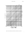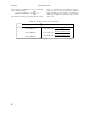
1
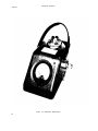
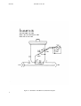
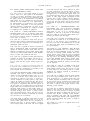
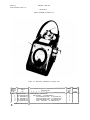
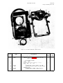
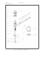
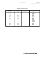
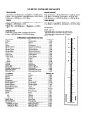
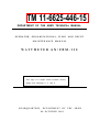
TM 11-6625-446-15
DEPARTMENT OF THE ARMY TECHNICAL MANUAL
OPERATOR, ORGANIZATIONAL, FIELD AND DEPOT
MAINTENANCE
MANUAL
WATTMETER AN/URM-120
This copy is a reprint which includes current
pages from Changes 3, 4
HEADQUARTERS,
and 5.
DEPARTMENT
OF
09 OCTOBER 1961
THE
ARMY
Changes in force: C3, C4 and C5
TM 11-6625-446-15
C5
Change
HEADQUARTERS
DEPARTMENT OF THE ARMY
Washington, DC, 17 November 1981
No. 5
Operator’s, Organizational, Direct Support, General
SUPPORT, AND DEPOT MAINTENANCE MANUAL
WATTMETER AN/URM-120
(NSN 6625-00-813-6430)
TM 11-6625-446-15, 9 October 1961, is changed as
follows: change title of the manual as shown above.
Page 1, paragraphs 1-2.1, 1-2.2, and 1-2.3 are
superseded as follows:
c. Discrepancy in Shipment Report (DISREP) (SF
361). Fill out and forward Discrepancy in Shipment
Report (DISREP) (SF 361) as prescribed in AR
55-38/NAVSUPINST 4610.33B/AFR 75-18/MCO
P4610.19C/DLAR 4500.15.
1-2.1. Index of Technical Publications
1-2.3. Reporting Errors and Recommending
Improvements
Refer to the latest issue of DA Pam 310-4 to determine
whether there are new editions, changes, modification
work orders (MWO’s) or additional publications
pertaining to the equipment.
1-2.2. Maintenance Forms, Records, and
Reports
a. Reports of Maintenance and Unsatisfactory
Equipment. Department of the Army forms and
procedures used for equipment maintenance will be
those prescribed by TM 38-750, The Army
Maintenance Management system (Army).
b. Report of Packaging and Handling Deficiencies.
Fill out and forward SF 364 (Report of Discrepancy
(ROD))
as prescribed in AR 735-11-2/DLAR
4140.55/NAVMATINST 4355.73/AFR 400-54/MCO
4430.3E.
You can help improve this manual. If you find any
mistakes or if you know of a way to improve the
procedures, please let us know. Mail your letter or DA
Form 2028 (Recommended Changes to Publications
and Blank Forms) direct to Commander, US Army
Communications-Electronics Command, ATTN:
DRSEL-ME-MQ, Fort Monmouth, NJ 07703. In
either case, a reply will be furnished direct to you.
Page 3. Add the following note after paragraph
4-2.
NOTE
Dummy loads DA-75, produced on contract
DAAB07-75 C-2450, require Coaxial
Adapter UG-999A (NSN-5935-00-501-8025)
to match the LC type connector on the load
to the N type connector on the wattmeter.
1
By Order of the Secretary of the Army:
E. C. MEYER
General, United States Army
Chief of Staff
Official:
ROBERT M. JOYCE
Brigadier General, United States Army
The Adjutant General
Distribution:
To be distributed in accordance with special mailing list.
2
TM 11-6625-446-15
NAVAER 16-45-709
Table of Contents
TABLE OF CONTENTS
Page
Section
I
1
INTRODUCTION AND DESCRIPTION . . .
1-1. Identification of Equipment . . . .
l-3. General Description . . . . .
1-9. Principles of Operation . . . .
.
.
.
.
II
SPECIAL SERVICE
2-1. Special Tools
.
.
III
PREPARATION FOR USE, STORAGE, AND SHIPMENT
3-1. Preparation for Use . . .
3-3. Preparation for Storage . .
3-5. Preparation for Shipment . .
3
OPERATION INSTRUCTIONS . . .
4-1.
Introduction
.
.
.
.
.
4-3. Connection of Coupler-Detector .
4-5. Purpose of Operating Controls .
4-8. Wattmeter Operation . . .
4-10. Interpreting Power Measurements
3
3
3
3
4
4
V
MAINTENANCE AND LUBRICATION
5-1. Maintenance . . . .
5-3.
Lubrication
.
.
.
.
7
7
7
VI
TROUBLE
SHOOTING
.
.
6-1. Trouble Shooting Analysis .
6-3. Trouble Shooting Procedure
7
7
7
OVERHAUL INSTRUCTIONS .
7-1. Special Overhaul Tools
.
7-3. Disassembly
7-7. Coupler-Detector . .
7-10. Primary Line . . .
7-12. Crystal Diode Assembly
7-14. Cleaning . . . .
7-16.
Inspection
.
.
.
7-18. Replacement . . .
7-20. Reassembly . . .
7-22. Calibration
7-24. Calibration Procedure . .
9
9
9
9
IV
VII
TOOLS . . . .
. . . . . .
.
.
1
1
3
3
3
.
.
.
.
.
.
.
.
.
.
9
9
9
10
10
10
.
VIII
INTRODUCTION TO ILLUSTRATED PARTS BREAKDOWN
12
IX
GROUP ASSEMBLY PARTS LIST . . . . . .
16
X
NUMERICAL
INDEX
.
20
XI
REFERENCE
DESIGNATION
. . . . .
21
.
.
.
.
.
INDEX
.
.
i
NAVAER 16-45-709
List of Illustrations
List of Tables
LIST OF ILLUSTRATIONS
Page
Title
Figure
1-1.
Wattmeter
AN/URM-120
.
1-2.
Wattmeter
AN/URM-120,
Schematic
4-1.
.
iv
.
.
2
Graph of Relation Between Incident Power, Reflected Power,
and VSWR . . . . . . . . . . .
.
.
5
7-1.
Coupler-Detector
.
.
11
9-1.
Wattmeter
.
.
16
9-2.
TS-1285/URM-120,
9-3.
Coupler-Detector,
Test
.
Set-up
AN/URM-120,
.
.
Oblique
Internal
.
.
.
Diagram
.
.
.
View
.
.
.
.
.
.
.
.
.
.
.
.
.
.
View
Views
Exploded
.
.
.
.
.
.
.
.
.
.
.
17
.
.
.
.
.
18
LIST OF TABLES
Page
Table
ii
1-1
Coupler-Detector Characteristics . . . . . . . . 1
4-1
Reflected
6-1
Trouble
8-1
Parts
Power
Shooting
Identification
Error
Table
Calculations
.
Procedure
.
.
.
.
.
.
.
.
.
6
.
.
7
.
.
.
.
.
.
.
.
.
.
.
.
.
.
15
NAVAER 16-45-709
iii
Section I
NAVAER 16-45-709
Figure 1-1. Wattmeter AN/URM-120
iv
Section I
Paragraphs 1-1 to 1-11
NAVAER 16-45-709
SECTION I
INTRODUCTION AND DESCRIPTION
1-1. IDENTIFICATION OF EQUIPMENT.
1-2. This publication contains instructions for operation and maintenance of Wattmeter AN/URN-120,
manufactured by Sierra Electronics Company, Menlo
Park, California, under Bureau of Aeronautics Contract
NOas 59-0238-f.
1-3. GENERAL DESCRIPTION.
1-4. Wattmeter AN/URM-120 (figure 1-1) is designed
to measure incident and reflected r-f power from 10
to 1000 watts within a frequency range of 2 to 1000
mc. Three coupler-detectors, each rated to cover a
portion of this frequency range (table 1-1), are supplied
with the wattmeter.
1-5. The wattmeter is housed in a small metal case
weighing about 6-1/2 pounds and is about 7 inches
wide, 6-5/8 inches high and 7-1/2 inches deep. It
contains a coaxial primary line, indicating meter, and
cable for interconnecting the meter to a coupler-detector. The coupler-detector has a knurled knob which
projects through a hole in the top of the wattmeter
case. On the knurled knob is a nameplate to indicate
power range, and centered on the nameplate is the
power range knob which can be rotated 360 degrees to
any desired power range. The coupler-detector rotates
only 180 degrees along the coaxial line. Two type-N
connectors, one male and one female, are located on
either side of the wattmeter case for connection between the power source and load.
1-6. Upper and lower parts of the wattmeter case are
held together with quick acting fasteners, which permit
easy access to the coupler-detector, the primary line,
and the indicating meter. The primary line is held
by four screws to the lower part of the case, and the
meter yoke is held against the inside front slope of
the case by four screws. Three plastic wedges, circled
by a metal band and clamp, keep the coupler-detector
seated above the primary line.
1-7. The coupler-detector is considered a separate
part of the wattmeter only in the sense that it can be
removed from the wattmeter case and replaced with
a similar unit differing only in frequency and power
characteristics. Three separate coupler-detectors are
supplied with the wattmeter. Selection of a particular
unit will depend upon the power source to be measured.
Characteristics of each coupler-detector are tabulated
in table 1-1.
1-8. Although the watt meter case assembly and couplerdetector function together, they can be stored separately
when not in use. Principle elements of the case assembly are the indicating meter and primary line of
the directional coupler.
1-9. PRINCIPLES OF OPERATION.
1-10. Power measurements are made by inserting the
proper coupler-detector and connecting the wattmeter
in series with the coaxial transmission line between the
load and the r-f power source. To determine incident
power, the arrow on the coupler-detector is rotated toward the load and the power range knob is positioned
for peak meter reading. The reading is taken directly
from the graduated meter scale which is made to correspond to the power range selected. Reflected power
is also determined by peak meter reading, but the
coupler-detector is rotated in the opposite direction
toward the r-f source.
1-11. In effect, rotation of the coupler-detector orients
the directional coupler which responds only to a wave
traveling in a particular direction on the primary transmission system, while being unaffected by a wave
traveling in the opposite direction on the primary line.
A standard diode rectifier in the coupler-detector
rectifies the energy picked up by the coupler. This
energy is then measured across a known 50-ohm impedance system and metered as incident or reflected
power. (See figure 1-2.)
TABLE 1-1. Coupler-Detector Characteristics
Insertion VSWR (Max. value with
type-N connectors on primary line)
Lowest
Power Range
3 Highest
Power Ranges
50, 100, 500, 1000
1.08
1.08
25-250
10, 50, 100, 500
1.08
1.05
200-1000
10, 50, 100, 500
1.08
1.05
Model No.
Freq. Range
(MC)
CU-753/URM-120
2-30
CU-754/URM-120
CU-755/URM-120
Power Range
(Watts)
1
Section I
NAVAER 16-45-709
Figure 1-2. Wattmeter AN/URM-120, Schematic Diagram
2
NAVAER 16-45-709
Sections II-IV
SECTION II
SPECIAL SERVICE TOOLS
2-1. SPECIAL TOOLS.
2-2. No special tools are required other than a standard screw driver and Allen wrench set.
SECTION III
PREPARATION FOR USE, STORAGE, AND SHIPMENT
3-1. PREPARATION FOR USE.
3-2. In preparing the wattmeter for use, open the case
and visually inspect the meter and directional coupler
for damage and dirt. If the unit does not appear in
good condition and cannot be corrected by following
the procedure outlined in Chapter V, the unit should be
replaced.
3-3. PREPARATION FOR STORAGE.
3-4. When storing the wattmeter, cover with a plastic
all-purpose cover or place wattmeter in a carrying
case, if one is supplied. The coupler-detectors must
be stored with a plastic cup placed over the secondary
line.
3-5. PREPARATION FOR SHIPMENT.
3-6. Special precautions against possible damage must
be taken when shipping the wattmeter. Make certain
that the unit is well wrapped and padded. A “fragile”
stamp must appear on the outside of the box.
SECTION IV
OPERATION INSTRUCTIONS
4-1. INTRODUCTION.
4-2. After determining that the r-f power source has
been turned off, connect the wattmeter in the transmission line either at the load or r-f source. Make
certain that connections are tight.
4-3. CONNECTION OF COUPLER-DETECTOR.
4-4. Use the following procedure for inserting the
coupler-detector:
a. Disengage the two quick action fasteners on sides
of wattmeter case.
b. Remove case cover.
c. Select proper coupler-detector from table 1-1.
d. Insert coupler-detector into receptacle on primary
line.
e. When coupler-detector appears to be properly
seated, snap receptacle clamp fastener closed.
f. Remove wire shunt from meter terminals.
g. Connect meter cable and replace cover on case.
4-5. PURPOSE OF OPERATING CONTROLS.
4-6. Only two controls are necessary to operate the
wattmeter. One is the knurled-topped coupler-detector
itself which can be rotated 180 degrees. The large
arrow on top of the coupler-detector will point in the
direction of power flow. For example, if the arrow
points toward the load it is in position for incident
power measurement. A circular nameplate with power
ranges etched on its surface is attached to the top of
each coupler-detector.
4-7. The power range knob, on top and in the center
of the nameplate, rotates within but independently of
the coupler-detector. The knob can be rotated 360
3
NAVAER 16-45-709
Section IV
Paragraphs 4-7 to 4-17
degrees to any desired power range shown on the circular nameplate. The power range knob adjusts the
distance between the secondary and primary lines by
extending or retracting the secondary line. For example,
the secondary line is moved closer to the primary line
for a 10-watt measurement than for a 1000-watt measurement.
4-8. WATTMETER OPERATION
4-9. Use the following procedure to operate the wattmeter:
a. Place power range knob in position higher than
rated power of r-f source.
NOTE
It is assumed that rated power of the r-f source
is known. If the rated power is not known,
place the power range knob in the highest power
position before the power source is turned on.
b. To measure incident power, rotate coupler-detector
so that power flow indicating arrow points toward load.
c. Apply r-f power to line under test.
d. Rotate power range knob from original power range
toward next lower power range, selecting proper power
range for measuring power of r-f source under test.
e. Observe point at which meter peaks and record
incident power reading.
f. To measure reflected power, set power range knob
to highest position and rotate coupler-detector so that
arrow points toward r-f source.
g. Repeat steps a through e . Record reading.
h. To check consistency of readings, repeat procedure
for incident power measurement and compare results
to reading originally obtained.
4-13. POWER ABSORBED BY LOAD. The r-fpower
absorbed by the load can be determined by subtracting
the reading of the reflected power from the reading of
the incident power. For example, if the incident power
reading is 50 watts and the reflected power reading is
5.5 watts, the power absorbed by the load is 50 watts
minus 5.5 watts or 44.5 watts.
4-14. ERRORS INCORPORATED IN MEASUREMENTS.
Because the wattmeter employs a peak reading type of
metering circuit calibrated on the basis of a sinsoidal
r-f waveform, it is subject to errors produced by harmonic distortion and by imperfect directivity of the
directional coupler. Harmonic distortion can be minimized by using a low-pass filter, but not too much can
be done about imperfect directivity.
4-15 To compensate for errors caused by imperfect
directivity and harmonic distortion, a ±5 percent fullscale tolerance is used in calculations of reflected
power. Percentage of error due to imperfect directivity in incident power measurements is for all practical
purposes negligible. However, error caused by harmonic distortion is appreciable and is taken into account. For example, suppose conditions indicate an
incident power of 40 watts and a reflected power of 2
watts. If the incident power is read on the 50-watt
scale, the error will not exceed ± 2.5 watts (± 5 percent times 50 watts full scale), regardless of the directivity of the coupler-detector.
4-16. The following is an example of how error is
accounted for in reflected power readings:
incident power = 40 watts
reflected power = 2 watts (reading taken with a couplerdetector having a directivity of 25db (300:1) on the
5-watt scale)
i. After power measurements have been completed,
replace wire shunt on meter terminals.
4-10. INTERPRETING POWER MEASUREMENTS.
4-11. In measuring r-f power, the wattmeter functions
as a test instrument to determine the efficiency of an
entire antenna system. This is done in two ways. The
first calculates the voltage standing wave ratio (VSWR)
of the load. The other method calculates the power
absorbed by the load.
4-12. VSWR MEASUREMET. The VSWR of the load
may be determined from the chart (figure 4-1) after
incident and reflected power meter readings have been
obtained. As an example, if the incident power is 50
watts and the reflected power is 5.5 watts, the VSWR
of the load is 2.0. This result is obtained by reading
the diagonal line which crosses the intersection of the
Pi vertical and Pr horizontal lines. For a more precise answer, the following formula can be used:
4
If the reflected power reading is taken with a couplerdetector having a directivity of 20db (100:1) and is indicated on the 5-watt scale, its error will be:
See table 4-1 for calculation of error in reflected power
measurement.
4-17. In addition to measuring incident and reflected
power, the wattmeter can also be used to determine the
percent of modulation by measuring power under modulated conditions (Pm) and power under c-w conditions
NAVAER 16-45-709
Section IV
Figure 4-1, Graph of Relation Between Incident Power, Reflected Power, and VSWR.
5
NAVAER 16-45-709
Section IV
(Pcw). Percent of modulation can then be calculated
by the following formula:
This formula is based on the principle that the average
power of a symmetrical wave modulated carrier increases over the c-w level because of the additional
power developed in the side bands. The wattmeter is
capable of measuring this increase in power because
of the detector square law characteristic and the linear
power scale.
TABLE 4-1 Reflected Power Error Calculations
Coupler-Detector Model No.
CU-753/URM-120
± 5% of full scale +
CU-754/URM-120
± 5% of full scale +
CU-755/URM-120
6
Reflected Power Error Calculations
measured incident power
500
measured incident power
500
power
± 5% of full scale + measured incident
500
NAVAER 16-45-709
Sections V-VI
SECTION V
MAINTENANCE AND LUBRICATION
5-1 MAINTENANCE.
5-2. Normal maintenance only should be required on
this instrument providing it receives normal use. When
the coupler-detector is removed, care must be taken
to prevent dirt or grit particles from entering the
primary line. Foreign particles should not be allowed to collect on the mating surfaces between the
coupler-detector and the primary line.
Wherever the coupler-detector is removed from
the primary line, the power range knob should
be set to the highest power range.
Use plastic cap provided to protect end of the
coupler-detector when it is not in use.
5-3. LUBRICATION
5-4. After disassembly or calibration of the wattmeter,
add a small dab of approved lubricant to the head of
each adjustment screw.
The coupling loop should not be cleaned because
any distortion in shape will destroy meter calibration.
SECTION VI
TROUBLE SHOOTING
6-1 TROUBLE SHOOTING
ANALYSIS.
6-2. Under certain conditions insertion of the power
wattmeter between the r-f source and the r-f load may
cause a change in the r-f power delivered to the load.
This occurs when the transmission line is mis-matched
at the r-f load. The result is an extension of the effective line length when the wattmeter is inserted. The
short section of line contained in the wattmeter changes
the electrical length of the system and therefore causes
a change in the impedance into which the power source
must work. This condition may be handled by one of
the following methods:
a. Retune or readjust r-f power source for normal
delivery.
b. Add section of transmission line to power wattmeter such that combined length of added section and
wattmeter equals one-half wavelength for frequency
in use. Remove added section when wattmeter is removed from system. The electrical length of wattmeter primary line with type-N connectors is 19.7 cm.
c. Permanently include short section of transmission
line in r-f load equal to electrical length of line contained within wattmeter. When using wattmeter, remove short section of line to maintain over-all electrical length of system transmission line.
6-3. TROUBLE SHOOTING PROCEDURE.
6-4. The following malfunctions (table 6-1) which can
occur in the watt meter are not the complete list, and
should be used only as a guide:
TABLE 6-1. Trouble Shooting Table (See figure 1-2)
Trouble
No meter indication for
incident or reflected
power.
Probable Cause
Remedy
1. Open resistor R102 in couplerdetector.
Replace part.
2. Shorted capacitor C101 or C102.
Replace part.
3. Shorted meter capacitor C103.
Replace part.
4. Meter shunt not removed.
Remove shunt.
7
Section VI
NAVAER 16-45-709
TABLE 6-1. Trouble Shooting Table (Cont)
Trouble
High VSWR
Intermittent or inconsistent meter
reading.
8
Probable Cause
Remedy
5. Coaxial cable from meter to couplerdetector disconnected or broken.
Repair cable.
6. Faulty diode CR101 in couplerdetector.
Replace diode.
7. Transmitter inoperative.
Turn on power.
1. Defective load.
Repair or replace.
2. Short or open transmission line.
Repair.
3. Corroded connectors.
Repair.
1. Faulty load.
2. Faulty transmission line.
3. Meter needle sticks.
Replace.
Replace or repair.
Check for bearing
damage.
Section VII
Paragraphs 7-1 to 7-17
NAVAER 16-45-709
SECTION VII
OVERHAUL INSTRUCTIONS
7-1. SPECIAL OVERHAUL TOOLS.
7-2. No special overhaul tools are required to overhaul the wattmeter. The only tools used include an
ordinary screwdriver, a No. 4 Allen wrench, and a
1/2-inch hexagonal socket wrench.
7-3. REASSEMBLY.
7-4. The indicating meter, coupler-detector, and primary line of the wattmeter can be removed only after
the case has been opened. To open the case (figure
9-1), release the quick-acting fasteners that hold the
upper and lower sections of the wattmeter case together.
h. Remove the two spring-retaining caps (13) and the
two slug-loading springs (12).
i. Using a low-wattage soldering iron, unsolder pickup
loop (18) from capacitor (14) and resistor (17) and remove pickup loop.
j. Remove capacitor (14) from insert in loop mounting
plate (15).
k. Remove resistor (17) from resistor mounting cup
(16) on loop mounting plate (15).
7-10. PRIMARY LINE.
7-5. METER.
7-11. The primary line is separated from the case by
removing the four mounting screws at the bottom of
the case.
7-6. To remove the meter from the upper section (figure 9-2), remove the four mounting screws that secure
the meter yoke and lift both the yoke and meter from
the case.
7-12. CRYSTAL DIODE ASSEMBLY.
7-13. Refer to figure 9-3 and disassemble the crystal
diode in accordance with the following procedure:
7-7. COUPLER-DETECTOR.
7-8. Three plastic wedges hold the coupler-detector
in the primary line. To remove the coupler-detector,
disconnect the meter cable from the side of the unit
and release the clamp holding the three plastic wedges
against the unit. Twist the unit and carefully pull up.
If the unit does not come free immediately, check the
plastic wedges to see that they are not interfering with
removal.
7-9. Refer to figure 9-3 and disassemble the couplerdetector in accordance with the following procedure:
a. Remove diode insulating washer (23) from crystal
diode (25).
b. Remove diode cap (24) from end of crystal diode (26).
NOTE
The diode cap is used only on coupler-detectors
No. 180-1000 and No. 181-1000.
c. Remove crystal diode (26); resistor-capacitor assembly consisting of capacitor (27), resistor (28), and
resistor insulating bushing (29); and tubing (31).
a. Using a small screwdriver, loosen setscrew in power
range knob (1) and remove knob.
b. Remove the two screws (2) and lockwashers (3) that
hold nameplate (4) machined knob (6) and remove
nameplate.
c. Using a l/2-inch hexagonal socket wrench, remove
the crystal diode assembly (23 through 34) from the
machined slug (11).
d. Using a No. 4 Allen wrench, remove the four screws
(5) that hold the machined knob (6) to the sleeve (21).
NOTE
When replacing the crystal diode, be sure to
wrap upper portion of diode with short strip
of l/4-inch Scotch tape.
7-14. CLEANING.
7-15. Periodically clean all internal and external surfaces of the wattmeter using a clean, lint-free cloth.
No attempt should ever be made, however, to clean the
coupling loop as any distortion in shape would destroy
meter calibration and accuracy.
e. Lift cam (9) from top of machined slug (11).
7-16. INSPECTION.
f. Lift machined slug (11) and its contents from sleeve
(21).
g. Remove the four screws (19) that secure the loop
mounting plate (15) to the bottom of machined slug (11).
7-17. Periodically inspect the wattmeter for evidence
of damage or wear. Special attention should be given
to the coupling loop and to the plastic inserts that hold
9
Section VII
Paragraphs 7-17 to 7-25
NAVAER 16-45-709
the coupler-detector in place. The loop must not be
displaced from its calibrated position.
7-18. REPLACEMENT.
7-19. The crystal diode is the only part requiring
special instructions for replacement. Replace the diode
in accordance with the following procedure:
a. Using a 1/2-inch hexagonal socket wrench, remove
crystal diode assembly from side of the coupler-detector.
b. Lightly tap side of coupler-detector assembly to
remove crystal diode.
c. Refer to Section IX for replacement crystal diode
part.
NOTE
When replacing a crystal diode be sure to wrap
upper portion of diode with short strip of l/4inch Scotch tape.
7-20. REASSEMBLY.
7-21. All reassembly procedures are made by reversing the order of disassembly as outlined in paragraph
7-3.
7-22. CALIBRATION.
7-23. The wattmeter may be recalibrated or checked
for accuracy by using the following equipment:
e. Power meter (Hewlett-Packard 430C special calibration at ±2 percent accuracy). This or any other
combination of power measuring equipment having
equivalent accuracy and standards may be used.
7-24. CALIBRATION PROCEDURE .
7-25. Calibration may be checked at any frequency
within the range of the coupler-detector involved. Connect the coupler-detector into the test setup shown in
figure 7-1 and proceed as follows:
a. Remove power range knob and circular nameplate
from top of coupler-detector.
b. Replace power range knob, being certain that set
screw is tightened on shaft flat.
c. Rotate knob to proper power range using circular
nameplate as guide. Arrow on nameplate should point
toward side of coupler-detector which contains meter
cable plug.
d. Rotate coupler detector to read power flowing toward termination.
e. Apply power from signal source and adjust level
until bolometer-power meter combination gives desired reading. Be sure to take into account the coupling
factor of the directional coupler at the frequency being
used.
f. Note reading on wattmeter meter.
NOTE
a. Appropriate power signal source.
b. Low-pass filter (Sierra Model 184 Series or HewlettPackard 360 Series).
c. Fifty-ohm terminations (Sierra Model 160 series).
d. Directional coupler (Sierra Model 138A or 150 with
special coupling factor calibration to ±0.16 db).
10
The reading on the wattmeter meter can be
adjusted within narrow limits by means of an
adjustment screw provided for each power range.
The adjustment screws are inside the couplerdetector and are accessible through holes in the
top of coupler-detector. The appropriate adjustment screw is adjacent to the dot or arrow
on the power range knob.
NAVAER 16-45-709
Section VII
Figure 7-1. Coupler-Detector Test Set-up
11
Section VIII
Paragraphs 8-1 to 8-17
NAVAER 16-45-709
SECTION VIII
INTRODUCTION TO ILLUSTRATED PARTS BREAKDOWN
8-1. PURPOSE OF BREAKDOWN.
8-2. This Illustrated Parts Breakdown provides information on components, assemblies, and detail parts
of Wattmeter AN/URM-120 for identification, requisitioning, issuance of parts, and for illustrating assembly
and disassembly relationships which can be used in
conjunction with Section VII of this handbook. This
breakdown is divided into four main categories; the
Introduction, the Parts List, the Numerical Index, and
the Reference Designation Index.
8-3. SCOPE OF BREAKDOWN.
8-4. This breakdown incorporates all details of the
nomenclatured item. The contract number, serial
number, and NAVAER type designation appear on the
name plate of the Wattmeter.
8-5. GROUP ASSEMBLY PARTS LIST.
8-6. GENERAL.
8-7. Each assembly listed is followed immediately by
its detail parts, properly indented thereunder to show
their relationship to the assembly. Detail parts of the
complete wattmeter which are not included in any assembly but which are used in conjunction with, which
attach to or which mount a certain assembly are listed,
in line with the major assembly, either preceding the
first detail part or following the last detail part of the
assembly.
while the detailed parts indented under the assemblies
are the quantities used per assembly. The quantities
specified, therefore, are not necessarily the total used
per wattmeter. Refer to the Numerical Index (Section
X) for the total quantities used per wattmeter.
8-13. USABLE ON CODE. Part variations within the
components of the wattmeter, due to slight differences
within the coupler-detector plug in assemblies are
identified by the letters A, B, or C, immediately following the description in the “Usable on Code” column.
In the cases where this column is left blank, the parts
listed are common to all wattmeters produced and delivered as part of this contract.
Usable on Code
Item
Coupler-Detector
Coupler-Detector
Coupler-Detector
CU-753/URM-120
CU-754/URM-120
CU-755/URM-120
A
B
C
8-14 NUMERICAL INDEX.
8-15. The Numerical Index (Section X) lists all the
identifying part numbers given in the Group Assembly
Parts List.
8-16. PART NUMBER LISTING.
8-17. The part numbers are listed in accordance with
the following numerical part-number filing system:
8-8. EXPLANATION OF COLUMN DETAILS.
8-9. FIGURE AND INDEX NUMBERS. The figure and
index numbers, which are numerically arranged in the
Group Assembly Parts List, are used mainly to assist
in locating a part in the Group Assembly Parts List
after it has been found in the Numerical Index.
8-10. PART NUMBERS. JAN or AN part numbers
are used, wherever available, to identify parts. Since
this instrument is a commercial item rather than one
which has been designed in accordance with JAN or AN
standards, most of the parts do not carry JAN or AN
identifying numbers. For those parts, the manufacturer’s identity is located in parentheses following the
description of the item.
8-11. DESCRIPTION. The description consists, principally, of a manufacturer’s, and JAN or AN drawing
title to identify each part.
8-12. UNITS PER ASSEMBLY. In the case of assemblies, the quantities listed in the “Units per Assy”
column of the Group Assembly Parts List are the total
quantities used per wattmeter at the location indicated,
12
a. The order of precedence in beginning the partnumber arrangement on the extreme left hand position
of the part number is as follows:
Letters A through Z
Numerals 0 through 9
NOTE
Alphabetical O’s are considered as numerical
zeros.
b. The order of precedence in continuing the partnumber arrangement on the second and succeeding
positions of the part number from left to right is as
follows :
Space (blank column)
Diagonal (/)
Point (.)
Dash (-)
Letters A through Z
Numerals 0 through 9
NAVAER 16-45-709
8-18. SOURCE CODES. MAITENANCE CODES, AND
RECOVERABILITY CODES.
8-19. Source codes are codes which indicate to a con-
sumer a source for a part required in the maintenance
or repair of an article. Specifically, these codes indicate whether the material is to be requisitioned from
the supply system; to be manufactured; to be obtained
from salvage; not to be replaced since the next higher
assembly is to be installed; not to be replaced due to
the impracticability of replacement; to be procured
for the specific requirement: to use local discretion
regarding obtaining a replacement; or failure of the
part indicates a requirement for complete overhaul
or scrapping of the assembly or equipment.
8-20. CODE “P” -- ITEMS PURCHASED, SUPPLY
SYSTEM STOCK. Code “P” is applied to items which
are purchased in view of known or anticipated usage
and which are relatively simple to manufacture within the Navy, if necessary.
8-21. Code “P1” is applied to items which are purchased in view of known or anticipated usage and which
are very difficult, impractical, or uneconomical to
manufacture within the Navy.
8-22. Code “P2” is applied to items for which little
usage is anticipated but which are purchased in limited
quantity for insurance purposes. Items coded “P2” are
difficult to manufacture, require special tooling and/or
stock not nor really available within the Naval establishment, or require long production lead time.
8-23. Code “P3” is applied to detail items which are
purchased in quantity in accordance with the life expectancy of the part. Items coded “P3” are deteriorative in nature and may require special storage conditions.
8-24. Code "P4" is applied to end items which are
procured for initial outfitting only and which are re-
placed by salvage, manufacture or assembly at the
lowest capable level of maintenance.
8-25. CODE “M” MANUFACTURE - ITEMS NOT PURCHASED. Code “M-F” is applied to items which are
capable of being manufactured within Class “C”, “D”,
“E” or “F” activities. Items coded “M-F” have no
anticipated or relatively low usage, or possess restrictive installation or storage factors. Code "M-F"
will not be applied to an item when the same item is
coded in the “P” series for other applications and system support is maintained; when the item appears in
the Navy Stock List of Federal Stores or the Electronic
Supply Office List of Common Electronic Parts in the
Electronic Supply System; or when supply support responsibility for the item has been vested in another
inventory manager. With respect to support equipment, the manufacturing activity may alter the design, material and processes provided that fit, function,
use, and safety are not impaired.
8-26. Code “M-O” is applied to items which are capable of being manufactured within Class “A” or “B” activities. Items coded “M-O” have no anticipated or
relatively low usage, or possess restrictive installation or storage factors. Code “M-O’ will not be applied
Section VIII
Paragraphs 8-18 to 8-33
to an item when the same item is coded in “P” series
for other applications and system support is maintained, when the item appears in the Navy Stock List
of Federal Stores or the Electronic Supply Office List
of Common Electronic Parts in the Electronic Supply
System; or when supply support responsibility for the
item has been vested in another inventory manager.
With respect to support equipment, the manufacturing
activity may alter the design, material and processes
provided that fit, function, use, and safety are not impaired.
8-27. CODE “A” -- ASSEMBLE-ASSEMBLY NOT
PURCHASED. Code “A-F” is applied to assemblies
which are not purchased but which are to be assembled
within Class “C”, “D”, “E” or “F” activities prior to
installation. At least one of the items in the assembly
must be a coded “P” series item which carries an individual part number and description.
8-28. Code “A-O” is applied to assemblies which are
not purchased but which are to be assembled within
Class “A” or “B” activities prior to installation. At
least one of the items in the assembly must be a coded
“P” series item which carries an individual part number and description.
8-29. CODE “N” - NOT STOCKED - WILL BE PURCHASED ON DEMAND. Code “N” is applied to items
which do not meet established criteria for stocking
and which are normally readily available from commercial sources. Items coded “N” will be purchased
on demand in accordance with applicable procedures.
This type item is for immediate consumption and will
not be stock numbered. With respect to support equipment, equivalent items may be substituted for specific
“N” coded items provided fit, function, use, and safety
are not impaired.
8-30. CODE ‘X”. Code “X” is applied to main structural members or similar items which, if required,
would suggest extensive repair. The need for an item,
or items, coded “X” will normally result in a recommendation for complete overhaul or retirement of
equipment from service.
8-31. Code “Xl” is applied to items for which purchase
of the next larger assembly source coded in the “P”
series is justified; e.g., an internal detail item, such
as welded segments inseparable from the assembly,
an item which must be machined and installed with
other items in a matched set, or an item of an assembly which, if required, would suggest extensive reconditioning of each assembly.
8-32. Code “X2” is applied to items which are not purchased for stock but may be acquired for use through
salvage or one time purchase. Activities requiring
such items will attempt to obtain from salvage; if not
obtainble from salvage, reasonably locally manufactured or procurable, such items will be requisitioned
through normal supply channels with supporting justification. Repeated requests may justify a change to
the “P” series code.
8-33. CODE “U”. Code “U” is applied when not of
supply significance.
13
Section VIII
Paragraphs 8-34 to 8-52
NAVAER 16-45-709
8-34. MAINTENANCE CODE DEFINTIONS. Maintenance codes as applied to purchased items are codes
which reflect known or anticipated usage at levels of
maintenance as defined in reference (b). Maintenance
code “O” indicates Class “A” or “B”. Maintenance
code “F” indicates Class “C”, “D”, "E" or "F". Maintenance codes shall be omitted from end item support
equipment. Maintenance codes as applied to manufacture and/or assembly are to be assigned as directed
by this instruction.
8-35. RECOVERABILITY CODE DEFINITIONS. Recoverability codes are codes which reflect the recoverability characteristics of items removed from equipment at time of maintenance, repair or overhaul; i.e.,
repairable, salvageable or consumable.
8-42. ALPHABETICAL PORTION OF REFERENCE
DESIGNATION . The following is an alphabetically
arranged list showing the type of part indicated by the
letters.
A
C
CR
E
J
L
M
O
a. Code "R" - Repairable. Items which are economical
and practical to repair on a scheduled basis. Replacements are obtained from the supply system on an exbe lost or damaged beyond recognition.
b. Code “S” - Salvageable. Items which are economical
and practical to salvage and which may be placed in
“Ready for Issue” condition. “S” coded items are not
normally scheduled in the overhaul program and may
contain items or materials which are usable, valuable
or critical, and which may be placed in the supply system for issue.
c. Code “C” - Consumable. Items that are neither repairable nor salvageable.
8-36. TOTAL QUANTITY.
8-37. The “Total Quantity” column in the Numerical
Index lists the total units required per wattmeter.
where more than one detail part, subassembly, or
assembly of a component is covered in the Illustrated
Parts Breakdown, the largest total quantity will be
shown.
Part
Letter
R
Y
Structural parts (panels, frames, castings,
etc.)
Capacitors of all types.
Rectifiers
Miscellaneous electrical parts (terminal
boards, insulators, knobs, brushes, etc.)
Jacks and receptacles (fixed connectors)
Inductors (r-f and a-f)
Meters of all types
Mechanical parts (bearings, shafts, etc.)
Resistors (fixed, variable, potentiometers)
Crystals, mechanical oscillators
8-43. NUMERICAL PORTION OF REFERENCE DESIGNATION. Normally, more complex electronic instruments and systems have reference designators assigned in such a manner that a quick identity can be
made to either an assembly, subassembly, or component. This wattmeter is relatively simple, having very
few electrical parts, and the reference symbols begin
at 100.
8-44. EXPLANATION OF TERMS, ABBREVIATIONS,
AND SYMBOLS.
8-45. TERMS.
8-46. The term “AR” in the quantity column indicates
bulk parts used “as required, ” while the term “Ref” in
the quantity column indicates that the item is listed
for “reference purposes” only.
8-47. ABBREVIATIONS.
8-48. The abbreviations used in this breakdown are
listed in ANA Bulletin No. 261.
8-49. MANUFACTURERS’ NAME CODE SYMBOLS.
8-38. REFERENCE DESIGNATION INDEX.
8-39. This index lists all reference designations shown
on the schematic diagram.
8-40. REFERENCE DESIGNATION.
8-41. A reference designation consists of one or two
capital letters followed by a group of numbers. These
combinations are used in order to identify a detail
part, subassembly, or assembly with respect to its
location in a photograph, schematic, or wiring diagram.
14
8-50. Normally, each part supplied by the manufacturer
for use by the prime contractor is identified as to its
manufacturer by a code symbol in parentheses following the description of the part in the Group Assembly
Parts List. This code will be furnished as a part o f
the first revision of this handbook when source codes,
etc. are assigned.
8-51. HOW TO USE THE ILLUSTRATED PARTS
BREAKDOWN.
8-52. To permit complete identification of all parts, the
procedure in table 8-1 is to be followed:
NAVAER 16-45-709
paragraphs
Section VIII
8-53 to 8-54
TABLE 8-1. Parts Identification Procedure
Use Applicable Procedure
raven
%ference
lesi~tion
Part
Number
Location
of Part
Stock Number
Part Number
a. Refer to Section XI.
b. Locate reference designation
c. Figure index, stock number, and part number are listed opposite
reference designation
Source Code
Figure Index
Quantity per Art ic le
a.
b.
c.
d.
e.
Refer to Section XI,
Locate reference designation.
Part number is listed opposite reference designation.
Refer to Sect ion X, using part number.
Source code, figure index, and quantity per article are listed
opposite part number.
Illustration
Part Number
Description
Units per
Assembly
Usable on Code
a.
b.
c.
d.
e.
Refer to Section XI.
Locate reference designation.
Figure index is listed opposite reference designation.
Refer to Section IX, using figure index.
Part number, description, units per assembly, and usable on code
are listed opposite the part number.
Stock Number
Source Code
Figure Index
Quantity per Article
a. Refer to Section X.
b. Locate part number.
c. Stock number, source code, figure index, and quantity per article
are list ed opposite the part number.
Illustration
Description
Units per Assembly
Usable on Code
a.
b.
c.
d.
e.
Illustration
Figure Index
Part Number
Description
Units per
Assembly
Stock Number
Source Code
Quantity per
Article
Refer to Section X.
Locate part number.
Figure index is listed opposite part number.
Refer to Section IX, using figure index.
Description, units per assembly, and usable on code are listed
opposite figure index.
a. Refer to Table of Contents.
b. Locate Group Assembly.
c. Page number is listed opposite Group Assembly.
d. Refer to Section DC, using page number.
e. Lmate figure index of part in illustration.
f. Refer to Group Assembly Parts Ltst followtng illustration, using
figure index.
g. Part number, description, units per assembly, and usable on code
are listed opposite figure number.
a. Refer to Table of Contents.
b. Locate Group Assembly.
c. Page nurd er is listed opposite Group Assembly.
d. Refer to Section IX, using page number.
e. Locate figure index of part in illustration.
f. Refer to Group Assembly Parts List followlng illustration, using
figure index.
g. Part number is listed opposite figure index.
h. Refer to Section X, using part number.
i. Locate part number.
j. Stock number, source code, and quantity per article are listed
opposite part number.
8-53. ORDERING SPARE PARTS.
8-54. Each Service using this list has established
certain depots and service groups for the storage and
issuance of spare parts to its organizations requiring
them. Tbe regulations of each Service should be studied
to determine the method and source for requisitioning
spare parts. The information in this list, as to manufacturer’s or contractor’s name, or the type, model,
or drawing number, is not to be interpreted as author-
ization to field agencies to attempt to purchase identical
or comparable spare parts directly from the manufacturer, or from wholesale or retail store, except
under emergency conditions, as covered by existing
regulations of the Service concerned. The parts chosen
for use in this instrument have probably been chosen
for special qualities not available in standard components, and the use of a standard component may result in decreased life or lowered performance.
15
NAVAER 16-45-709
Section IX
Group Assembly Parts List
SECTION IX
GROUP ASSEMBLY PARTS LIST
Figure 9-1. Wattmeter AN/URM-120, Oblique View
FIG. &
INDEX
NO.
9-1
-1
-2
-2
-2
-3
16
PART
NO.
AN/URM-120
TS-1285/URM-120
CU-753/URM-120
CU-754/URM-l2O
CU-755/URM-120
CY-2606/URM-120
1
2
3
4
DESCRIPTION
5
6
7
WATTMETER AN/URM-120
WATTMETER
TS-1285/URM-120
:
:
:
:
.
.
.
COUPLER-DETECTOR CU-753/URM-120 .
.
.
COUPLER-DETECTOR CU-754/URM-120 .
COUPLER-DETECTOR CU-755/URM-120 .
.
.
CASE, Wattmeter CY-2606/URM-120 . .
.
.
UNITS
PER
ASSY
1
1
1
1
1
1
USABLE
CODE
NAVAER 16-45-709
Section IX
Group Assembly Parts List
Figure 9-2. TS-1285 URM-120, Internal Views
FIG. &
INDEX
No.
9-2-1
PART
No.
1
118X5
3
4
5
METER, Power (see figure 9-1, item 1 for next
higher assembly)
-2
-3
-4
-5
-6
-7
-8
-9
2
DESCRIPTION
6 7
146X1O
14X103
.
146X12
146X13
.
.
(ATTACHING PARTS)
YOKE,
Meter
.
.
.
.
.
.
.
.
SCREW, Rd hd, No. 6-32 by 1 in. lg . . .
NUT, Hex, No. 6-32 . . . . . .
---*--.
CONNECTOR, Coaxial, female, type MB .
CAPACITOR, Fixed, ceramic, 0.01 mfd, 450V dc
PRIMARY LINE
.
CONNECTOR, Coaxial, male, type N . .
.
CONNECTOR, Coaxial, female, type N .
UNITS
PER
ASSY
USABLE
ON
CODE
1
1
4
4
1
1
1
1
17
Section IX
Group Assembly Parts List
NAVAER 16-45-709
Figure 9-3. Coupler-Detector, Exploded View
18
NAVAER 16-45-709
FIG. &
INDEX
No.
PART
NO.
-1
160X10
-2
-3
2
.
COUPLER-DETECTCOR CU.
KNOB, 1-1/4 in. OD
-4
-4
-4
SP-10176-2
195X14
195X15
-5
.
.
.
.
.
.
.
.
.
.
.
.
-6
-9
SP-7288-3
SP-10438-3
.
.
.
.
-10
SP-4987-1
.
.
-11
-11
-12
-13
-14
SP-10080-3
SP-7287-3
SP-4872-1
SP-4855-1
18A142-SS
.
.
.
.
.
.
.
.
.
.
-14
18A281
.
.
-14
18A500
.
.
-15
-15
-15
-16
-16
-17
-18
-18
-18
SF-10078-2
SP-4850-2
SP-7285-2
SP-7583-1
SP-6832-2
50X680
SP-7545-2
SP-6557-1
SP-6556-1
.
.
.
.
.
.
.
.
.
.
.
.
.
.
.
.
.
.
.
.
.
.
.
.
.
.
.
.
.
.
.
.
.
.
.
.
-19
-20
-21
-21
-22
-22
SP-4864-1
SP-7543-2
SP-4857-2
SP-10095-2
SP-10095-1
-23
-25
SP-4985-1
-26
-26
-27
105X4
105X2
26B102
.
.
.
.
.
.
-28
52X182
.
.
-28
-29
-30
-31
-32
-33
-34
52X271
SP-4847-1
SP-4848-1
.
.
.
.
.
.
.
.
.
.
.
.
.
.
SP-4845-1
146X11
4
UNITS
PER
ASSY
DESCRIPTION
5
6
7
1
9-3
3
Section IX
Group Assembly Parts List
1
1
ABC
.
.
1
1
ABC
ABC
.
.
.
1
1
1
A
B
C
4
ABC
1
1
ABC
ABC
4
ABC
1
1
2
2
1
A
BC
ABC
ABC
A
1
B
1
C
1
1
1
1
1
1
1
1
1
A
B
C
A
C
ABC
A
B
C
4
A B C
1
1
1
1
1
1
1
1
ABC
A
BC
AB
C
ABC
ABC
ABC
1
1
1
AC
ABC
1
AC
1
1
1
1
1
1
1
B
ABC
ABC
ABC
ABC
ABC
ABC
/URM-120
(ATTACHING PARTS)
SCREW, Fil hd No. 2-56 by 3/16 in. lg
LOCKWASHER, Int tooth, No. 2 . .
---*--NAMEPLATE
.
.
.
.
.
NAMEPLATE
.
.
.
.
.
.
NAMEPLATE
.
.
.
.
.
.
USABLE
ON
CODE
(ATTACHING PARTS)
SCREW, Soc hd, cap, No. 4-40 by 3/4 in. lg
- - - *- - KNOB
.
.
.
.
.
.
.
.
.
CAM
.
.
.
.
.
.
.
.
.
(ATTACHING PARTS)
SCREW,
Modified
.
.
.
.
.
.
---*--SLUG
.
.
.
.
.
.
.
.
.
SLUG
.
.
.
.
.
.
.
.
.
SPRING,
Slug
loading
.
.
.
.
.
.
.
CAP, Spring retaining .
CAPACITOR, Fixed, mica, button 1400 mmfd
500V dc
CAPACITOR, Fixed, mica, button 280 mmfd
500V dc
CAPACITOR, Fixed, mica, button 52.5 mmfd
500V dc
PLATE, Loop mounting, machined . .
PLATE,
Loop
mounting,
cast
.
.
.
PLATE, Loop mounting, machined
CUP,
Adj.
resistor
mounting
.
.
.
CUP, Adj, resistor mounting
RESISTOR, Fixed, comp, 68 ohms, 1/2 w, 5%
LOOP, Power pickup, 4 turns . . .
LOOP, Power pickup, 1 turn . . . .
LOOP, Power pickup, 1 turn . . . .
.
(ATTACHING PARTS)
SCREW, Flt hd, No. 4-40 by 1/4 in. lg .
---*--PIN,
stop
.
.
.
.
.
.
.
.
SLEEVE
.
.
.
.
.
.
.
.
SLEEVE
.
.
.
.
.
.
.
.
CAP
.
.
.
.
.
.
.
.
.
CAP
.
.
.
.
.
.
.
.
.
DIODE,
Crystal,
subassembly
.
.
.
.
WASHER,
Diode
insulating
.
.
.
.
TAPE, Scotch cellophane, 1/4 in. wd by
1 in. lg
.
DIODE,
Silicon,
cartridge
.
.
.
.
DIODE,
Silicon,
cartridge
.
.
.
.
CAPACITOR, Fixed, ceramic, button,
1000 mmfd, 500v dc
.
RESISTOR, Fixed, comp 1500 ohms, 1/2 w
10%
.
RESISTOR, Fixed, comp 270 ohms 1/2 w 10%
.
BUSHING, Resistor insulating . .
.
CONTACT,
Connector
.
.
.
.
.
TUBING, Vinyl, black, 1/4 in. lg . .
.
ADAPTER,
Connector
.
.
.
.
.
LOCKWASHER,
Int
tooth
.
.
.
.
CONNECTOR, Coaxial, male, type MB
.
19
Section X
Numerical Index
NAVAER 16-45-709
SECTION X
NUMERICAL INDEX
STOCK NO.
20
PART NO.
FIGURE AND
INDEX NO.
CU-753/URM-120
CU-754/URM-120
CU-755/URM-120
SP-4845-1
SP-4847-1
SP-4848-1
SP-4850-2
SP-4855-1
SP-4857-2
SP-4864-1
SP-4872-1
SP-4985-1
SP-4987-1
SP-6556-1
SP-6557-1
SP-6832-2
SP-7285-2
SP-7287-3
SP-7288-3
SP-7543-2
SP-7545-2
SP-7583-1
SP-10078-2
SP-10080-3
SP-10095-1
SP-10095-2
SP-10176-2
SP-102438-3
TS-1285/URM-l20
14X103
18A142-SS
18A281
18A500
26B102
50X680
52X182
52X271
105X2
105X4
118X5
146X10
146X11
146X12
146X13
160X10
195X14
195X15
9-2-10
9-2-10
9-2-10
9-3-32
9-3-29
9-3-30
9-3-15
9-3-13
9-3-21
9-3-20
9-3-12
9-3-23
9-3-10
9-3-18
9-3-18
9-3-16
9-3-15
9-3-11
9-3-6
9-3-21
9-3-18
9-3-16
9-3-15
9-3-11
9-3-22
9-3-22
9-3-4
9-3-9
9-1
9-2-6
9-3-14
9-3-14
9-3-14
9-3-27
9-3-17
9-3-28
9-3-28
9-3-26
9-3-26
9-2-1
9-2-5
9-3-34
9-2-8
9-2-9
9-3-1
9-3-4
9-3-4
SOURCE CODE
TOTAL
QUANTITY
1
1
1
3
3
3
1
6
2
3
6
3
12
1
1
1
1
2
3
1
1
1
1
1
1
2
1
3
1
1
1
1
1
3
3
2
1
1
2
1
1
3
1
1
3
1
1
NAVAER 16-45-709
Section XI
Reference Designation Index
SECTION XI
REFERENCE DESIGNATION INDEX
REFERENCE
DESIGNATION
FIGURE
INDEX
C101
9-3-14
C102
C103
CR101
9-3-27
9-2-3
9-3-26
J101
J102
J103
L101
9-2-9
9-2-8
9-3-34
9-3-18
M101
P101
R101
R102
9-2-1
9-2-5
9-3-17
9-3-28
STOCK NO.
PART NO.
18A142-SS
18A281
18A500
26B102
14X103
105X2
105X4
146X13
146X12
146X11
SP-6556-1
SP-6557-1
SP-7545-2
118X5
146X10
50X680
52X182
52x271
21
HEADQUARTERS,
DEPARTMENT OF THE ARMY
W
ASHINGTON
25, D.C., 9
October
1961
TM 11-6625-446-15 (a reprint of Navy publication NAVWEPS 16-45-709, 1 June 1959), is
published for the use of Army personnel.
B
Y
O
RDER
OF
THE
S
ECRETARY
OF
THE
A
R M Y:
G. H. DECKER,
Official:
General, United States Army,
Chief of Staff.
J. C. LAMBERT,
Major General, United States Army
The Adjutant General.
Distribution :
Actit,e Artny:
DASA (6)
USASA (2)
CNGB (1)
Tech Stf, DA (1) except
CSigO (15)
Tech Stf Bd (1)
USCONARC (4)
USA ARTYBD (1)
USA ARMBD (2)
USAIB (1)
USA RADBD (2)
USA ABE LCTBD ( )
USA AVNBD (1)
USAATBD (1)
ARADCOM (2)
ARADCOM Rgn (2
OS Maj Cored (2)
OS Base Cored (2)
LOGCOMD (2)
MDW (1)
Armies (2)
Corps (5)
USATG AD (2)
USATC Armor (2)
USATC Engr (2)
USATC FA (2)
USATC Inf (2)
Svc College (2)
Br Svc Sch (2)
GENDEP (2) except
Atlanta GENDEP (None)
Sig See, GENDEP (5)
Sig Dep (12)
Ft Monmouth (63)
USA Cot’PS (1)
AFIP (1)
WRAMC (1)
AFSSC (1)
USAEPG (2)
Ekf C (1)
USACA (2)
USASEA (1)
USA Carib Sig Agcy (1)
USA Sig Ms] Spt Agcy (12)
USASSA (20)
USA SSAMRO (1)
Army P]ctorial Cen (2)
USAOMC (3)
USA Trans Tnl] Cored (1)
Army Tml (1)
POE (1)
OSA (1)
AMS (1)
Sig Fld Maint Shops (2)
JBUSMC (2)
Units org under fol TOE:
11-7 (2)
11-16 (2)
11-57 (2)
11-97 (2)
11-117 (2)
11-155 (2)
11-500 (A A-AE) (4)
11-557 (2)
11-587 (2)
11 592 (2)
11-597 (2)
NG: None.
USAR: None.
For explanation of abbreviations used, see AR 320-50,
GPO
022–735
1
THE METRIC SYSTEM AND EQUIVALENTS
PIN: 023303-005
This fine document...
Was brought to you by me:
Liberated Manuals -- free army and government manuals
Why do I do it? I am tired of sleazy CD-ROM sellers, who take publicly
available information, slap “watermarks” and other junk on it, and sell it.
Those masters of search engine manipulation make sure that their sites that
sell free information, come up first in search engines. They did not create it...
They did not even scan it... Why should they get your money? Why are not
letting you give those free manuals to your friends?
I am setting this document FREE. This document was made by the US
Government and is NOT protected by Copyright. Feel free to share,
republish, sell and so on.
I am not asking you for donations, fees or handouts. If you can, please
provide a link to liberatedmanuals.com, so that free manuals come up first in
search engines:
<A HREF=http://www.liberatedmanuals.com/>Free Military and Government Manuals</A>
– Sincerely
Igor Chudov
http://igor.chudov.com/