1
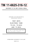
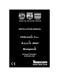
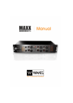
TM 11-6625-508-10 DEPARTMENT OF THE ARMY TECHNICAL MANUAL OPERATOR’S MANUAL SIGNAL GENERATORS AN/USM-44 AND AN/USM-44A This reprint includes all changes in effect at the time of publication; change 1. HEADQUARTERS, DEPARTMENT OF THE ARMY SEPTEMBER 1962 TM 11-6625-508-10 C1 TECHNICAL MANUAL SIGNAL GENERATORS AN/USM-44 AND AN/USM-44A OPERATOR’S MANUAL TM 11-6625-508-10 HEADQUARTERS, DEPARTMENT OF THE ARMY WASHINGTON 25, D.C., 9 May 1963 CHANGES No. 1 TM 11-6625-508-10, 20 September 1962, is changed as follows: Page 2. Add paragraphs 1-5.1 and 1-5.2 after paragraph 1-5. and records in accordance with instructions in TM 38750. 1-5.1. Index of Publications b. Report of Damaged or Improper Shipment. Fill out and forward DD Form 6 (Report of Damaged or Improper Shipment) as prescribed in AR 700-58 (Army), NAVSANDA Publication 378 (Navy), and AFR 71-4 (Air Force). Refer to the latest issue of DA Pam 310-4 to determine whether there are new editions, changes, or additional publications pertaining to your equipment. DA Pam 310-4 is an index of current technical manuals, technical bulletins, supply bulletins, lubrication orders, and modification work orders that are available through publications supply channels. The index lists the individual parts (-10, -20, -35P, etc.) and the latest changes to and revisions of each equipment publication. c. Comments on Manual. Forward all comments on this publication direct to Commanding Officer, U. S. Army Electronics Materiel Support Agency, ATTN: SELMS-MP, Fort Monmouth, N. J. DA Form 2028 Recommended changes to DA Technical Manual Parts Lists or Supply Manuals 7, 8, or 9 will be used. 1-5.2. Forms and Records Page 20. Add section III.1 after section III. a. Reports of Maintenance and Equipment Improvement Recommendations. Use equipment forms Section III.1. MAINTENANCE INSTRUCTIONS 3-1.1. Scope of Operator’s Maintenance 3-1.2. Preventive Maintenance The maintenance duties assigned to the operator of Signal Generators AN, USM-44 and AN/USM-44A are listed below together with a reference to the paragraphs covering the specific maintenance function. The duties assigned do not require tools or test equipment other than those issued with the set. Preventive maintenance is the systematic care, servicing, and inspection of equipment to prevent the occurrence of trouble, to reduce downtime, and to assure that the equipment is serviceable. a. Daily maintenance service and inspection (par. 3-1.4). b. Weekly maintenance service and inspection (par. 3-1.5). c. Cleaning (par. 3-1.6). TAGO 9131A--May a. Systematic Care. The procedures given in paragraphs 3-1.4, 3-1.5, and 3-1.6 cover systematic care essential to proper upkeep and operation of the signal generator. The cleaning operations (par. 3-1.6) should be performed once a day. If the equipment is not used daily, the cleaning operations must be performed before operation after any extended shutdown, or once a week while the equipment is kept in standby condition. The other items must be checked before the equipment is placed in operation after a shutdown, during operation, or after it is turned off, as specified in the applicable paragraph. be remedied by the operator, higher echelon maintenance or repair is required. Records and reports of these inspections must be made in accordance with TM 38-750. b. Maintenance Service and Inspection. The maintenance service and inspection charts (pars. 3-1.1 and 3-1.5) outline inspections to be made a; specific intervals. These inspections are made to determine combat serviceability; that is, to determine that the equipment is in good general (physical) condition, in good operating condition, and likely to remain combat serviceable. To assist operators in determining and maintaining combat serviceability, the charts indicate what to inspect, how to inspect, and what the normal conditions are; the references column lists the paragraph that contains additional information. If the defect cannot 3-1.3. Maintenance Service and Inspection Periods Maintenance service and inspection of Signal Generators AN,/USM-44 and AN/USM-44A is required daily and weekly. Paragraphs 3-1.4 and 3-1.5 specify the items to be inspected and serviced. In addition to the routine services and inspections, the equipment should be reinspected and serviced immediately before going on a mission and as soon after completion of the mission as possible. 3-1.4. Daily Maintenance Service and Inspection Chart Item Procedure NO. Item Normal condition or result 1 COMPLETENESS: Inspect the equipment for Equipment must be complete (table I). completeness. 2 INSTALLATION. Inspect the equipment for Installation is in accordance with paragraph 2proper installation. 3. 3 CLEANLINESS: Inspect for cleanliness. Signal generator must be clean and dry inside and out; free of grease, dirt, rust, corrosion, and fungus. 7 SWITCHES, KNOBS, AND DIALS: Inspect for Items are firmly attached. Action is positive excessive looseness Check for proper without backlash, binding, or scraping. mechanical action by setting each control to each of its settings. 8 METERS: Check for broken glass windows. Windows should not be chipped, broken, or cracked. 16 PILOT OR INDICATING LAMP: Inspect for Lamp should light when equipment is turned burned-out lamps. on. 17 OPERATIONAL CHECK: Refer to section III. Refer to section III. 3-1.5. Weekly Maintenance Service and Inspection Chart Item Procedure NO. Item Normal condition or result 4 PRESERVATION: Inspect for preservation. Painted surfaces must be free of bare spots, rust, and corrosion. 9 CORDS AND CABLES: Inspect for cuts, Power cord and signal cables should be free of cracks, strain, and fraying. cuts, cracks, strains, and fraying. 10 HANDLES AND LATCHES: Check for Handles and latches should be properly looseness. fastened to the equipment. References Par. 3-1.6. References AGO 9131A 2 dirt from the case; use a cloth dampened (not wet) with cleaning compound. 3-1.6. Cleaning Inspect the exterior of the signal generator. The exterior surfaces should be clean and free of dust, dirt, grease, and fungus. c. Remove dust or dirt from connectors with a brush. a. Remove dust and loose dirt with a clean soft cloth. Caution: Do not press on the meter faces (glass) when cleaning; the meter may be damaged. Warning: Cleaning Compound (Federal stock No. 793095-9542) and its fumes are toxic. Provide adequate ventilation. Do not use near a flame. d. Clean the front panel, meters, and control knobs; use a soft clean cloth. If dirt is difficult to remove, dampen the cloth with water; mild soap may be used to make the cleaning more effective. b. Remove grease, fungus, and ground-in Page 22. Add the appendix after table V. APPENDIX REFERENCES Following is a list of applicable publications available to the operator of Signal Generator AN/USM-44(*). DA Pam 310-4 TM 38-750 Index of Technical Manuals, Technical Bulletins, Supply Bulletins, Lubrication Orders, and Modification Work Orders. The Army Record System and Procedures. AGO 9131A 3 By Order of the Secretary of the Army: EARLE G. WHEELER, General, United States Army, Chief of Staff. Official: J. C. LAMBERT, Major General, United States Army, The Adjutant General. Distribution: Active Army: DASA (6) USASA (2) CNGB (1) Cof Engrs (1) TSG (1) CSigO (5) CofT (1) USA CD Agey (1) USCONARC (5) USAMC (5) ARTDCOM (2) ARADCOM Rgn (2) OS Maj Comd (3) OS Base Comd (2) LOGCOMD (2) USAECOM(5) USAMICOM (3) USASCC (4) MDW (1) Armies (2) Corps (2) USA Corps (3) USATC AD (2) USATC Engr (2) USATC Inf (2) USATC Armor (2) Instls (2) except Ft Monmouth (63) Svc College (2) Br Svc Sch (2) GENDEP (OS) (2) Sig Dep (OS) (12) Sig Sec, GENDEP (5) Army Dep (2) except Ft Worth (8) Lexington (12) Sacramento (28) Tobyhanna (12) USA Elct RD Actv, White Sands (13) USA EIct Rd Actv, Ft Huachuca (2) USA Trans Tml Comd (1) Army Tml (1) POE (1) USAOSA (1) AMS (1) WRAMC (1) AFIP (1) Army Pic Cen (2) USA Mbl Spt Cen (I) USA Elct Mat Agcy (25) Chicago Proc Dist (1) USARCARIB Sig Agcy (I) Sig Fid Maint Shop (3) JBUSMC (2) Units org under fol TOE: Two copies each UNOINDC: 11-7 11-157 11-16 11-500 (AA-AC) (4) 11-57 11-557 11-98 11-587 11-117 11-592 11-155 11-597 NG: State AG (3); units-same as active army except allowance is one (1) copy to each unit. USAR: None. For explanation of abbreviations used, see AR 320-50. AGO 9131A 4 NAVAER 16-30USM44-501 Table of Contents TABLE OF CONTENTS Section I. Page GENERAL DESCRIPTION...................................................................................................................................1 1-1. 1-6. 1-7. 1-8. 1-9. 1-16. 1-25. 1-29. 1-31. 1-32. 1-33. 1-34. 1-35. 1-36. 1-37. 1-38. 1-39. 1-40. II. OPERATING PROCEDURES............................................................................................................................11 2-1. 2-3. 2-7. 2-9. 2-11. 2-13. 2-15. 2-17. 2-19. 2-21. 2-23. 2-28. III. Scope of Procedures.............................................................................................................................11 Installation .............................................................................................................................................11 Operating Controls, Dials and Terminals ..............................................................................................11 Turning on the Equipment .....................................................................................................................11 Setting the TS-510/U, TS-510A/U for Continuous Wave Operation .....................................................15 Setting the TS-510/U TS-510A/U for Internal Sine Wave Modulation...................................................17 Setting the TS-510/U TS-510A/U for External Sine Wave Modulation .................................................17 Setting the TS-510/U TS-510A/U for Pulse Modulation ........................................................................17 Using the TS-510/U Frequency Calibrator ............................................................................................18 Using the TS-510A/U Frequency Calibrator..........................................................................................18 Signal Generator Loading Considerations ............................................................................................18 Turning Off the Equipment ....................................................................................................................19 OPERATING CHECKS AND ADJUSTMENTS ..................................................................................................20 3-1. IV. Identification ............................................................................................................................................1 General Description of Complete Equipment ..........................................................................................2 Equipment Supplied ................................................................................................................................2 Equipment Required but Not Supplied ....................................................................................................2 General Description.................................................................................................................................2 Electrical Characteristics .........................................................................................................................5 Transit Case ............................................................................................................................................7 Accessories .............................................................................................................................................7 Differences in Equipment ......................................................................................................................10 FINE FREQ. ADJUST Control..............................................................................................................10 Crystal Calibrator, TS-510/U .................................................................................................................10 Crystal Calibrator, TS-510A/U...............................................................................................................10 Output Attenuator Control, TS-510/U and TS-510A/U(*) ......................................................................10 Output Attenuator Control, TS-510A/U(**) ............................................................................................10 Internal Modulation, TS-510/U and TS-510A/U(*).................................................................................10 Internal Modulation, TS-510A/U(**).......................................................................................................10 External Pulse Modulation, TS-510/U and TS-510A/U(*)......................................................................10 External Pulse Modulation, TS-510A/U(**)............................................................................................10 General..................................................................................................................................................20 EMERGENCY OPERATION AND REPAIR .......................................................................................................21 4-1. 4-4. Introduction............................................................................................................................................21 Electron Tube Complement ..................................................................................................................21 i List of Illustrations List of Tables NAVAER 16-30USM44-501 LIST OF ILLUSTRATIONS Figure 1-1. 1-2. 1-3. 1-4. 1-5. 1-6. 1-7. 1-8. 2-1. 2-2. 2-3. 2-4. 4-1. Page Signal Generator AN/USM-44 (Hewlett-Packard), Equipment Supplied..................................................iv Signal Generator AN/USM-44A (Hewlett-Packard), Equipment Supplied................................................ 1 Signal Generator AN/USM-44A (Nuclear Electronics), Equipment Supplied........................................... 2 Signal Generator TS-510/U (Hewlett-Packard) ........................................................................................ 4 Signal Generator TS-510A/U (Hewlett-Packard) ..................................................................................... 5 Signal Generator TS-510A/U (Nuclear Electronics)................................................................................. 6 Transit Cases, CY-1605/USM-44 and CY2105/USM-44A ....................................................................... 9 Accessory Cover .................................................................................................................................... 10 Signal Generator TS-510/U (Hewlett-Packard) Front Panel Controls.................................................... 13 Signal Generator TS-510A/U (Hewlett-Packard) Front Panel Controls ................................................. 14 Signal Generator TS-510A,/U (Nuclear Electronics) Front Panel Controls............................................ 15 Diagram Showing Relationships of Front Panel Controls to Major Circuits ........................................... 16 Tube Location Diagram .......................................................................................................................... 21 LIST OF TABLES Table I II III IV V Title Page Equipment Supplied ...................................................................................................................................3 Specifications for Signal Generators TS-510/U and TS-510A/U................................................................8 Controls and Terminals ............................................................................................................................12 Power Losses as Related to VSWR in Generator Load...........................................................................18 Electron Tube Complement .....................................................................................................................22 ii NAVAER 16-30USM44-501 1. Transit Case Assembly 2. Signal Generator Assembly 3. Cable Assembly CX-3135/U 4. Cable Assembly CG-409/U 5. Accessory Cover 6. Fuse-holder and Adapter Figure 1-1A. Signal Generator AN/USM-44A, Equipment Supplied iii Section I NAVAER 16-30USM44-501 Figure 1-1. Signal Generator AN,/USM-44 (Hewlett-Packard), Equipment Supplied iv NAVAER 16-30USM44-501 Section I Paragraphs 1-1 to 1-4 SECTION I GENERAL DESCRIPTION 510A/U shown in figure 1-5. The main component of Signal Generator Test Set AN/USM44A manufactured by the Nuclear Electronics Corporation under Order No. N383-46472 is the Signal Generator TS-510A/U shown in figure 1-6. This equipment is manufactured in accordance with Specification MIL-G-7702 (AER), dated 15 November 1953. 1-1. IDENTIFICATION. (See figures 1-1, 1-2, and 1-3.) 1-2. This publication comprises operating instructions for Signal Generator Test Set AN/USM-44 (figure 1-1) and Signal Generator Test Set AN/USM-44A (figure 1-2) manufactured by the Hewlett-Packard Company, Palo Alto, California, and Signal Generator Test Set AN/USM44A (figure 1-3) manufactured by the Nuclear Electronics Corporation, Philadelphia, Pennsylvania. 1-4. Throughout this handbook references to Signal Generator TS-510A/U will be construed to mean all models; references to Signal Generator TS-510A/U (*) refer specifically to the Signal Generator TS-510A/U manufactured by the Nuclear Electronics Corporation under Order No. N383-46472; and, references to Signal 1-3. The main component of Signal Generator Test Set AN/USM-44 is Signal Generator TS-510/U (see figure 14). The main component of Signal Generator Test Set AN/USM-44A manufactured by the Hewlett-Packard Company under Orders No. NOasN38333733A, N38336708A, and N383-47671A is the Signal Generator TS- Figure 1-2. Signal Generator AN/USM-44A (Hewlett-Packard), Equipment Supplied 1 Section I Paragraphs 1-5 to 1-9 NAVAER 16-30USM44-501 Figure 1-3. Signal Generator AN/USM-44A (Nuclear Electronics), Equipment Supplied Generator TS-510A/U (**) refer specifically to the Signal Generator TS-510A/U manufactured by the HewlettPackard Company under Orders No. NOasN38333733A, N383-36708A, andN383-46471A. The information contained in this handbook is applicable to Signal Generator TS-510/U and all models of Signal Generator TS-510A/U unless otherwise indicated. 1-7. EQUIPMENT SUPPLIED. Refer to Table I for a tabular list of the equipment supplied. 1-8. EQUIPMENT REQUIRED BUT NOT SUPPLIED. To use the crystal calibrator, included as an Integral part of this equipment, a 600-ohm high-impedance headset, or the equivalent, must be provided by the operator. When external modulation of the signal generator is desired, an external source of modulating voltage must be provided by the operator. 1-5. Other publications applicable to this equipment are: a. Handbook of Service Instructions, NAVAER 1630USM44502. 1-9. GENERAL DESCRIPTION. (See figures 1-1, 1-2, and 1-3.) Signal Generator AN/USM-44 is the nomenclature assigned to Signal Generator TS-510/U and its accessories, and Signal Generator AN/USM-44A is the nomenclature assigned to Signal Generator TS510A/U and its accessories. This equipment is complete, self-contained, transportable, and includes, in addition to the signal generator instrument itself, the following accessories: A water-tight transit case, power and r-f cables, connector adapters, and an output fuseholder for protection of the r-f output attenuator. b. Handbook of Overhaul Instructions, NAVAER 1630USM44-503. c. Illustrated i630USM44.-504. Parts Breakdown, NAVAER 1-6. GENERAL DESCRIPTION OF COMPLETE EQUIPIMENT. (See figures 1-1, 1-2, and 1-3.) 2 NAVAER 16-30USM44-501 Section I Table I. Equipment Supplied OVERALL DIMENSIONS (in.) QUANTITY ITEM AN TYPE DESIG. PER EQUIP. Signal Generator AN/USM-44 (Hewlett-Packard). (See figure 1-1.) 1 Signal Generator TS-510/U WEIGHT (lb) HEIGHT or LENGTH WIDTH DEPTH 16 13-3/4 20 62 1 Transit Case CY-1605/USM-44 24 20 17-5/8 32 1 Cord CX-3135/U (6 ft, 0 in.) 72 - - 0.6 2 Cord CG-409 /U (4 ft, 0 in.) 48 - - 0.2 1 Connector Adapter UG-201A/U - - - - 1 Connector Adapter UG-349A/U - - - - 1 R-f Output Fuse Mount MX-1730/U 4-5 /8 3 /4 dia - 0.4 2-7/8 3/4 dia - 0.2 16 13-3 /4 20 62 1 R-f Amplifier Tube Wrench -(located in chassis clips) Signal Generator AN/USM 44A (Hewlett Packard). (See figure 1-2.) 1 Signal Generator TS-510A/U 1 Transit Case CY-2105/USM-44A 24 20 17-5/8 32 1 Cord CX-3135/U (8 ft, 0 in.) 96 - - 0.8 2 Cord CG-409/U (4 ft, 0 in.) 48 - - 0.2 1 Connector Adapter, UG-201A/U - - - - 1 Connector Adapter UG-349A/U - - - - 1 R-f Output Fuse Mount MX-1730/U 4-5 /8 3/4 dia - 0.4 2-7/8 3/4 dia - 0.2 16 24 13-3/4 20 20 17-5/8 62 32 1 R-f Amplifier Tube Wrench -(located in chassis clips) Signal Generator AN/USM-44A (Nuclear Electronics). (See figure 1-3.) 1 Signal Generator TS-510A /U 1 Transit Case CY-2105A/USM-44A 1 Cord CX-3135/U (6 ft, 0 in.) 72 - - 0.6 1 Cord CG-409/U (4 ft, 0 in.) 48 - - 0.2 2 Connector Adapter UG-201A/U - - - 1 Connector Adapter UG-349A/U - - - 1 R-f Output Fuse Mount MX-1730/U 4-5/8 3/4 dia - 0.4 1 R-f Amplifier Tube Wrench (located in chassis clips) 2-7/8 3/4 dia - 0.2 -- 3 Section I Paragraphs 1-10 to 1-12 NAVAER 16-30USM44-501 1-10. The TS-510A,/U VHF Signal Generator is a general purpose test instrument capable of furnishing accurately adjustable radio frequency signals from 0.1 microvolt to 0.5 volt in amplitude over a frequency range from 10 to 420 megacycles. The instrument may be amplitude modulated by internally generated sine waves or by externally applied sine waves or pulses. The TS510A/U includes a built-in crystal-controlled heterodyne calibrator which permits the operator to adjust the output frequency to a high degree of accuracy. This particular circuit includes a front panel switch for selecting either of two beat frequencies, 1 or 5 megacycles, which will appear throughout the range of the signal generator. The output signal level is adjusted by an attenuator, calibrated in both volts and decibels below 1 milliwatt (dbm), and can be read directly to an accuracy of +2 db over the full frequency range without the use of external pacts, monitoring devices, or charts. The instrument features straightforward operation through the use of reliable, direct-reading controls and meters throughout. With its high quality output signal, the TS510A/U is especially suitable for applications requiring a minimum of incidental amplitude or frequency modulation. 1-11. Signal Generator TS-510A/U is designed to meet the exacting requirements of precision laboratory work as well as for general application in the 10to 420megacycle frequency range. The equipment can be used for testing, calibrating, or troubleshooting VHF radio equipment and measuring standing wave ratios, antenna and transmission line characteristics, and receiver sensitivity when used in con]unction with other test apparatus. In order to obtain utmost accuracy for these and similar applications, particular care has been taken in the design of the instrument to hold spurious modulation to a very low value under all operating conditions. 1-12. The TS-510A/U Signal Generator is housed in an aluminum cabinet finished in light gray non-reflecting paint. Figure 1-4. Signal Generator TS-510/U (Hewlett-Packard) 4 NAVAER 16-30USM44-501 Bow (guardrail type) handles attached to the front panel provide assistance in handling the instrument and protection for the controls and indicators located on the panel. Ventilation is provided by louvers in the side and back surfaces of the cabinet. The chassis is removable by loosening four screws in the rear of the cabinet. 1-13. All r-f signal circuits and the output attenuator are housed 1ii an aluminum diecasting divided into three compartments. For ease in r-f tube replacement, all three r-f tribes are located In the uppermost compartment, separate from the tuned circuits. This compartment is accessible by removing the small plate under the frequency dial drum. The compartments containing the tuned circuits are accessible when the side plate is removed. 1-14. All controls, meters, and terminals are located on the front panel and are marked with large, black-filled, engraved letters. The frequency dial is of the drum type with a scale length of 11-3/4 inches for each band, or approximately 59 inches for the entire range. The full Section I Paragraphs 1-13 to 1-17 frequency range is covered is five bands, each band being read on a separate dial scale. An automatically positioned pointer indicates the scale in use. Except for the headset jack and the power connector receptacle, all connectors on the front panel are of the BNC type. All fuses for the equipment are replaceable from the front panel. 1-15. Standby heaters are provided for the purpose of maintaining higher than ambient temperature within the cabinet during periods of intermittent use, thereby preventing frequent condensation and moisture. 1-16. ELECTRICAL CHARACTERISTICS. (See figures 1-4, 1-5 and 1-6.) 1-17. Signal Generator TS-510/U is capable of generating a continuously adjustable r-f output signal throughout a frequency range of 10 to 420 megacycles, as indicated on a direct-reading dial. The frequency dial calibration is accurate to better than 0.5%. Figure 1-5. Signal Generator TS-510A/U (Hewlett-Packard) 5 Section I Paragraphs 1-18 to 1-19 NAVAER 16-30USM44-501 Calibration accuracy may be improved by employing the crystal-controlled heterodyne calibrator, which provides checkpoints at every multiple of 5 megacycles over the entire frequency range of the equipment. The frequency dial index is adjustable by a small knurled knob on the front panel so that the dial calibration can be set exactly on frequency at any calibrator checkpoint. The checkpoint signals are obtained by connecting a headset (not part of the equipment) to the XTAL CAL. OUTPUT Jack. The calibrator is accurate to ±0.01% of 5 mc, provides better than 0.1 milliwatt of power to a 600-ohm headset, and is adjustable in output by the XTAL CAL. GAIN control. In addition to the above, Signal Generator TS-510A/U provides checkpoints of 1 megacycle over the entire frequency range of the equipment. accuracy of ±2 db or better over the entire frequency and attenuation range when the Instrument is connected to an external 50-ohm resistive load. The internal impedance of the generator, as seen at the output jack, is 50 ohms over the full frequency range; when connected to a 50-ohm resistive load, the VSWR due to mismatch will not be greater than 1.2 (SWR of 1.6 db). 1-19. The r-f output signal from the TS-510/U may be amplitude modulated bh internally generated 400and 1000-cycle sine waves or by externally applied sine waves above 4 volts rms over a frequency range from 20 cps to 100 kc or by externally applied pulses above approximately 10 volts. When pulse modulated, the instrument is capable of generating pulses of radio frequency energy as short as 4 microseconds at r-f signal frequencies above 40 megacycles and as short as 1 microsecond above 220 megacycles. 1-18. An output attenuator, calibrated to be read directly in both volts and decibels, provides continuous adjustment of the output signal from +4 to -127 dbm (350 millivolts to 0.1 microvolt) and may be read to an Figure 1-6. Signal Generator TS-510A/U (Nuclear Electronics) 6 NAVAER 16-30USM44-501 The degree of sine wave modulation is continuously variable from 0 to 95% by a front panel control, Modulation of the r-f signal is continuously displayed on a direct reading percent modulation meter having an accuracy of ±10% or better. 1-20. The envelope of the sine-wave-modulated signal contains less than 5%, distortion for modulation percentages below 30%, and less than 10%, distortion for modulation percentages between 30% and 50%. Incidental amplitude modulation of the CW output signal is less than 0.1%. The level of harmonics and spurious signals contained in the CW output signal is 40 decibels below the level of the output signal when the output level is greater than 200 microvolts. 1-21. The TS-510/U is especially suitable for aligning narrow-band a-m receivers. In such applications, during actual receiver alignment, a significant amount of spurious f-m In the generator may result in mis-tuning of the receiver due to unwanted detection by the selectivity characteristic of the i-f amplifier in the receiver. To keep spurious f-m to a negligible value, the instrument employs a master oscillator-power amplifier (MOPA) type of r-f generator circuit. Modulation is Introduced at the power amplifier stage and has little or no effect on0 the frequency of the oscillator. A buffer stage between the oscillator and amplifier further isolates the oscillator. The effectiveness of these measures is such that sourious fm is less than 0.001% at 30% modulation for frequencies below 100 megacycles and less than 1000 cps above 100 megacycles. 1-22. To minimize r-f leakage, all r-f signal circuits are housed in an aluminum casting, the access covers of which are sealed with wire braid. Leakage is such that when the output signal is adjusted for 0.1 microvolt, the conducted signal leakage at any other front panel connector and the radiated leakage two inches from the instrument are each less than 1.0 microvolt. 1-23. All plate circuits in the instrument are operated from regulated d-c voltage. In addition, the heaters in the r-f oscillator, buffer, and power amplifier tubes are operated from regulated square wave power generated by a multivibrator. This measure effectively provides greater overall stability of the system. The TS-510/U is designed to operate from a nominal 115-volt, 50to 1000cycle, single-phase a-c power source and consumes approximately 180 watts of power. Signal Generator TS510A/U(*) is designed to operate from a nominal 115volt, 50to 420-cycle, single-phase a-c power source. Signal Generator TS-510A/U(**) is designed to operate from a nominal 115-volt, 50to 1000-cycle, single-phase a-c power source and consumes approximately 195 watts of power. 1-24. Further information is given In table II. 1-25. TRANSIT CASE. (See figure 1-7.) Section I Paragraphs 1-20 to 1-30 1-26. Transit Case CY-1605/USM-44 is a watertight carrying case provided for shipment and storage of Signal Generator TS-510/U along with the accessories and instruction books supplied with the AN/USM-44 equipment. The transit case is constructed of a special laminated material consisting of wood covered on each side with aluminum sheeting. The cover for the transit case is provided with a double lip which is filled with sponge rubber. The double lip effects a weather-tight seal when the cover for the case is closed. The cover is attached to the case by eight trunk-type latches. (See figure 1-7.) 1-27. Transit Case CY-2105/USM-44A is a watertight carrying case provided for shipment and storage of Signal Generator TS-510A/U(**) along with the accessories and instruction books supplied with the AN/USM-44A equipment. Its construction is similar to Transit Case CY-1605/USM-44. 1-28. Transit Case CY-2105A,/USM-44A is a watertight carrying case provided for shipment and storage of Signal Generator TS-510A/U(*) along with the accessories and instruction books supplied with the AN/USM-44A equipment. Its construction is similar to Transit Case CY-1605./USM-44. 1-29. ACCESSORIES. 1-30. The equipment accessories consist of 3 cables, 2 connector adapters, and I fuse mount. (See figure 1-1.) Equipment descriptions and purposes are as follows: a. Cord CX-3135/U(6 ft) is the power cord for the TS-510/U and consists of a 6-foot length of 3-conductor cable terminated on one end by a 3-contact female AN type connector for connection to the front panel power receptacle on the signal generator; the other end is terminated in a dual purpose plug which may be connected either to a standard 2-conductor a-c outlet or to a special 3-conductor type. A removable third contact blade which screws to the body of the plug grounds the chassis of the instrument when used with the appropriate a-c power receptacle. A similar cord, Cord CX-3135/U(8 ft) is the power cord for the TS-510A/U(**). It is 8 feet long. Cord 2273 is the power cord for the TS-510A/U(*). b. Cord CG-409/U(4 ft) is the signal input cable for the TS-510/U and TS-510A/U(**). It consists of approximately 4 feet of RG-58/U cable with a UG260/U plug on each end. Cord 2429 is the signal input cable for the TS-510A/U(*). Two of these signal input cables are supplied with the instrument. c. Connector Adapter UG-201A/U is a BNC male to Type N female adapter; it is included as an accessory for convenience in making cable connections to the signal generator. (See figure 1-8.) d. Connector Adapter UG-349A/U, included for the same purpose, is a BNC female to Type N male adapter. (See figure 1-8.) 7 Section I NAVAER 16-30USM44-501 Table II. Specifications for Signal Generators TS-510/U and TS-510A/U TYPES OF OUTPUT: CW; Internal sine-wave amplitude modulation; External amplitude modulation; External pulse modulation. FREQUENCY RANGE: 10 to 420 megacycles covered in five bands. ACCURACY OF FREQUENCY CALIBRATION: CRYSTAL CALIBRATOR: OUTPUT VOLTAGE: OUTPUT LEVEL METER: OUTPUT LEVEL CALIBRATION ACCURACY: OUTPUT LEVEL AND RATED LOAD: INTERNAL MODULATION: EXTERNAL MODULATION: PERCENT MODULATION: ENVELOPE DISTORTION FOR SINE WAVE: MODULATION: INPUT IMPEDANCE FOR EXT SINE MODULATION: EXTERNAL PULSE MODULATION: INPUT IMPEDANCE FOR EXT PULSE MODULATION: FREQUENCY STABILITY: INPUT POWER REQUIREMENTS: With crystal calibrator, ±0.05%0/ at checkpoints. Without calibrator, ±0.5% overall. *5 megacycle oscillator accurate to ±0.01% providing checkpoints at each 5 megacycles over full frequency range. Provides 0.1 milliwatt or better to a 600-ohm headset. **5 megacycle oscillator accurate to ±0.01% providing checkpoints at each 1 megacycle and 5 megacycles over the full frequency range. **'1 megacycle oscillator accurate to +0.01% providing checkpoints at each 1 megacycle over the full frequency range Continuously adjustable attenuator provides from 0.1 microvolt minimum to 0.5 volt maximum when operated into rated load of 50 ohms. Monitors r-f power level fed to output attenuator; calibrated 0 to 7 dbm and 0.1 to 0.5 volt. For all conditions of operation the accuracy of the attenuator dial is within ±2 decibels when operated into a rated load. ***The accuracy of the attenuator dial is ±1 db over entire frequency range into a 50-ohm resistive load. The VSWR measured at the output connector is less than 1.2 (SWR 1.6 db) when connected to nominal 50-ohm resistive load. Sine waves at frequencies of 400 and 1000 cps ±5%, (±10%**). Percent modulation continuously adjustable from zero to 95% at output levels up to 0 dbm. 100 to above 20,000 cps. Percent modulation continuously adjustable from zero to 95% at r-f output levels up to 0 dbm with modulating voltages from 4 to 25 volts rms. Indicated by direct-reading panel meter accurate to ±10%. Less than 5% at 30% modulation for frequencies from 100 to 5000 cps. Less than 10% at 50% modulation. 20,000 ohms shunted by 50 microfarads. Positive 10-volt (5-volt***) peak pulse required. Combined rise and decay time of r-f output pulse less than 4 microseconds from 40 to 220 megacycles; less than 1 microsecond from 220 to 420 megacycles. Residual level at least 20 db below 0.5 peak pulse output. 50,000 ohms shunted by 40 micromicrofarads. Frequency drift less than 0.005% per 15-minute period. 115/230 volts ac, single phase. (**115 volts ac, single phase.) *Pertains only to TS-510./U **Pertains only to TS-510A,/U(*) ***Pertains only to TS-510A/U(**) 8 NAVAER 16-30USM44-501 TRANSIT CASE CY-2105/USM-44A TRANSIT CASE CY-1605/USM-44 Figure 1-7. Transit Cases, CY-1605/USM-44 and CY-2105/USM-44A 9 Section I Section I Paragraphs 1-31 to 1-40 NAVAER 16-30USM44-501 Figure 1-8. Accessory Cover e. R-f Output Fuse Mount MX-1730/U. a special coaxial fuseholder for protection of the output attenuator, is included as an accessory for the TS-510/U and the TS-510A/U(**) Signal Generators. This fuse protects the output attenuator from damage in the event that an external voltage is accidentally applied at the RF OUTPUT. The fuseholder connects to the output cable and is provided with 2 standard female Type N output connectors. A Type 8AG, 1/16-amp fuse is utilized. The fuseholder has an insertion loss of 0.05 db at 200 mc, 0.56 db at 300 mc, and 0.65 db at 400 mc; its VSWR is not greater than 1.35 when connected to a 50-ohm resistive load. (See figure 1-8.) A similar fuseholder, 2152, is included as an accessory for the TS-510A/U(*) Signal Generator. increments over the full frequency range. It also provides 0.1 milliwatt or better to a 600-ohm headset. 1-35. OUTPUT ATTENUATOR CONTROL, TS-510/U AND TS-510A/,U(*). (See figures 2-1 and 2-2.) The accuracy of the attenuator dial Is within ±2 decibels for all conditions of operation at rated load. 1-36. OUTPUT ATTENUATOR CONTROL, TS510A/U(**). (See figure 2-3.) The accuracy of the attenuator dial is within ±1 decibel for all conditions of operation at rated load. 1-37. INTERNAL MODULATION, TS-510/U AND TS510A,/U(**). Sine waves are obtainable at frequencies of 400 and 1000 cps ±5%. Percentage modulation is continuously adjustable from 0 to 95% at output levels up to 0 dbm. 1-31. DIFFERENCES IN EQUIPMENT. 1-32. FINE FREQ. ADJUST CONTROL. Beginning with serial number 510, the TS-510/U Signal Generators are equipped with a short range incremental tuning device for making extremely small changes in the output signal frequency. The FINE FREQ. ADJUST control is operated by an additional knob on the front panel and provides from 0.01 to 0.2% adjustment in the output frequency after selection by the main frequency control dial. The addition of the FINE FREQ. ADJUST control does not alter the circuit, operation, or specifications for the signal generator. The FINE FREQ. ADJUST control is illustrated in figures 2-2 and 2-3, item 28. 1-38. INTERNAL MODULATION. TS-510A/U(**). Sine waves are obtainable at frequencies of 400 and 1000 cps ±10%. Percentage modulation is continuously adjustable from 0 to 95% at output levels up to 0 dbm, 1-39. EXTERNAL PULSE MODULATION,TS-510/U AND TS-510A/U(*). Positive 10-volt peak pulse is required. The combined rise and decay time of the r-f output is less than 4 microseconds from 40 to 220 megacycles; and less than 1 microsecond from 220 to 420 megacycles. Residual level must be at least 20 db below 0.5 peak pulse output. 1-33. CRYSTAL CALIBRATOR, TS-510/U. The calibrator is a ±5 megacycle oscillator, accurate to ±0.01%, providing checkpoints at each 5 megacycles over the full frequency range. It also provides 0.1 milliwatt or better to a 600-ohm headset. 1-40. EXTERNAL PULSE MODULATION, TS510A/U(**). Positive 5-volt peak pulse is required. The combined rise and decay time of the r-f output is less than 4 microseconds from 40 to 220 megacycles; and less than 1 microsecond from 220 to 420 megacycles. Residual level must be at least 20 db below 0.5 peak pulse output. 1-34. CRYSTAL CALIBRATOR, TS-510A/U. The calibrator is a 1 to 5 megacycle oscillator, accurate to +0.01%, providing checkpoints in 1 megacycle 10 NAVAER 16-30USM44-501 Section II Paragraphs 2-1 to 2-10 SECTION II OPERATING PROCEDURES Handbook of Service Instructions. Model TS510A/U(*) operates only from a nominal 115-volt, 50 to 420 cps single-phase power source. On all models, the power cord supplied for connecting the signal generator to a power source is equipped with a special three-conductor male plug. The third contact on the plug is attached directly to the metal plug body and through the cable to the chassis of the instrument. When It is desired to ground the signal generator chassis, the third blade may be used with outlets designed for this plug, or a wire lead may be connected between the plug body and an external ground such as the a-c receptacle box. The third contact (ground contact) may be easily removed so that the plug can be connected to the standard 115volt ac outlet. 2-1. SCOPE OF PROCEDURES. 2-2. This section Illustrates and describes the operating controls for the TS-510/U and TS-510A/U and gives step-by-step procedures for operating the signal generator in each mode of operation: continuous wave, internal sine modulation, external sine modulation, and external pulse modulation. All procedures usually require that the instrument first be set up for CW operation to establish the exact frequency and power output requirements; the signal generator is then switched to the desired mode of operation. Instructions for using the crystal controlled frequency calibrator and for loading the output of the signal generator are also included. Material In this section is as follows: 2-3 2-7 2-9 2-11 2-13 2-15 2-17 2-19 2-21 2-23 2-28 2-6. If the signal generator has been subjected to conditions which may create moisture or condensation, such as rapid changes in temperature. dry any moisture which may be present. Allow the instrument to warm up for as long as possible before using it. When the signal generator is to remain idle for extended periods of time, it should be stored in the transit case provided to keep moisture and dust from entering the cabinet and to prevent possible damage. Installation. Operating Controls, Dials, and Terminals. Turning On the Equipment. Setting the Equipment for Continuous Wave Operation. Setting the Equipment for Internal Sine Wave Modulation, Setting the Equipment for External Sine Wave Modulation. Setting the Equipment for Pulse Modulation. Using the Frequency Calibrator (TS-510/U). Using the Frequency Calibrator (TS-510A/U). Signal Generator Loading Considerations. Turning Off the Equipment. 2-7. OPERATING CONTROLS, TERMINALS. DIALS AND 2-8. The front panel operating controls, dials, and terminals for the TS-510/U and the TS-510A/U are listed with their functions in Table III and are shown in figures 2-1, 2-2, 2-3, and 2-4. Figure 2-1 shows the front panel layout for the TS-510/U. figure 2-2 shows the front panel layout for the TS-510A/U(*), and figure 2-3 shows the front panel layout for theTS-510A/U(**). A simple block diagram showing which circuits in the signal generator are affected by the various front panel controls is shown in figure 2-4. 2-3. INSTALLATION. 2-4. Since the TS-510/U or the rs-510A,/U is portable equipment designed for test-bench use and not for permanent installation, no special installation procedure is necessary. Both the signal generator and the equipment under test should be within arms’ reach of the operator, with connecting leads between the equipments kept as short as possible. CAUTION Do not obstruct the ventilating louvers on the sides of the instrument cabinet. Safe operating temperature depends on free air flow through these louvers. 2-9. TURNING ON THE EQUIPMENT. 2-10. To place TS-510/U or TS-510A/U Signal Generator in operation, proceed as follows: a. With the power switch in OFF position, connect the power cord to the signal generator and to a 115-volt a-c power source. The HEATER pilot lamp lights, indicating that the internal space heaters are in operation. 2-5. Models TS-510/U and TS-510A/U(**) operate from a nominal 115/230-volt, 50 to 1000 cps single-phase power source. If the equipment is to be operated from a 230-volt source, the power transformer primary connections must be changed as indicated In the 11 Section II NAVAER 16-30USM44-501 Table III. Controls and Terminals REF. NO. 1 2 3 4 5 6 DESIGNATION Power Receptacle AC 3 AMP (fuse) SPARES (fuses) DC 0.25 AMP (fuse) SPARES (fuse) HEATER (pilot lamp) 7 8 9 10 Power Switch POWER (pilot lamp) MOD. SELECTOR FREQUENCY RANGE (selector) 11 *FREQUENCY (control) (see figure 2-3) or **Frequency Control (see figures 2-1 and 2-2) MEGACYCLES (indicator) AMP. TRIMMER (control) OUTPUT LEVEL (control) OUTPUT VOLTS-DBM (indicator) Output Attenuator (control) 12 13 14 15 16 17 18 19 20 21 22 23 RF OUTPUT (jack) XTAL CAL. OUTPUT (connector) XTAL CAL. GAIN (control) EXT. MOD. (jack) MOD. LEVEL (control) PERCENT MODULATION (indicator) ZERO (screwdriver adjustment) 24 25 EXT. PULSE (jack) Frequency dial index adjustment FUNCTION Receives power from power cord supplied. Protects power source and instrument against short circuits. Replacement 3 amp fuses. Protects the internal power supply against short circuits. Replacement 0.25 amp fuse. Pilot lamp indicates power is applied to generator and space heaters are in operation. In the ON position all circuits of the signal generator are energized. Pilot lamp indicates when main circuits are energized. Adjusts signal generator circuits for desired type of operation. Selects frequency range and positions the range pointer on MEGACYCLES dial. Controls the output frequency in combination with the FREQUENCY RANGE switch Indicates frequency of the r-f output signal directly in megacycles. Tunes r-f power amplifier for maximum output. Adjusts the r-f power level existing at input to output attenuator. Indicates r-f power level existing at input to output attenuator. Selects and indicates the r-f output signal level in microvolts, millivolts, and decibels. Output connector for r-f output signal (see CAUTION). Connects headset to crystal calibrator. Adjusts loudness of beat frequency signal from frequency calibrator. Receives sine wave from external source for modulation of r-f output signal. Adjusts modulation percentage to desired value. Indicates the percentage modulation of the r-f output signal. Electrically sets the modulation meter to zero with instrument in operation with no modulation applied. Receives pulses from external source for modulation of the r-f output signal. Adjusts frequency dial index over short range. 12 NAVAER 16-30USM44-501 Section 11 Table III. Controls and Terminals (cont) REF. NO. 26 27 28 DESIGNATION Frequency dial lock Attenuator dial lock FINE FREQ. ADJUST FUNCTION Locks frequency dial. Locks attenuator dial. Adjusts RF OUTPUT frequency increments. 29 *1 MC OFF 5 MC 29 **1 MC OFF 5 MC Selects 1 megacycle and 5 megacycle outputs or no output (OFF position). Selects 1 megacycle and 5 megacycle outputs or no output (OFF position). *Used only on Signal Generator TS-510A/U(**) **Used only on Signal Generators TS-510/U and TS-510A/IU(*) Figure 2-1. Signal Generator TS-510/U (Hewlett-Packard) Front Panel Controls 13 in very small Section II NAVAER 16-30USM44-501 Figure 2-2. Signal Generator TS-51OAt/U (Hewlett-Packard) Front Panel Controls b. Turn the power switch to the ON position. The HEATER pilot lamp should extinguish as the POWER pilot lamp lights, indicating that power is no longer being supplied to the space heaters but is being applied to all circuits of the signal generator. must be taken when working with "transceiver" type apparatus, such as the AN/ ARC-27 equipment, to insure that the transmitter remains inoperative while the signal generator is connected to the equipment antenna. c. Place the MOD. SELECTOR In the CW position and the OUTPUT LEVEL control to near maximum. Other controls may be set in any position before turning on the generator. NOTE For protection of the output attenuator on the TS-510/U and the TS-510A/U(**), a special fuseholder MX-1730/U is supplied for connection to the RF OUTPUT Jack or cable. A similar fuseholder, 5152, is supplied with the TS-510A/U(*). When using the signal generator for any application where there is a possibility of voltage being applied at the RF OUTPUT jack, this fuse must be used between the signal generator and the external equipment. d. After an approximate 1 minute warm-up, adjust the AMP. TRIMMER for maximum reading on the OUTPUT VOLTS meter and set the OUTPUT LEVEL control to obtain a reading at SET LEVEL on the OUTPUT VOLTS meter. CAUTION Do not apply an external r-f or d-c voltage to the RF OUTPUT jack on the signal generator. To do so can burn out the impedance-matching network in the output attenuator. Special care 14 NAVAER 16-30USM44-501 Section II Paragraphs 2-11 to 2-12 Figure 2-3. Signal Generator TS-510A ’U (Nuclear Electronics) Front Panel Controls FOR c. Set the MEGACYCLES indicator to the desired frequency. 2-12. For CW operation the TS-510/U and TS510A/U supply a continuous wave output signal of up to 5 milliwatts in power across an external 50-ohm load (0.5 volt) with the output level directly indicated to an accuracy of better than ±2 db for all conditions of operation. The TS-510A/U(**) has an output level calibration accuracy of ±1 db over the entire frequency and attenuation range. When set for CW operation, the MOD. LEVEL control is inoperative and may be set to any position; however, the PERCENT MODULATION meter monitors the output signal during all types of operation and may display momentary fluctuations resulting from switching transients. For continuous wave operation, proceed as follows: d. Set the OUTPUT LEVEL control to near maximum and adjust the AMP. TRIMMER for maximum output as indicated on OUTPUT VOLTS meter. 2-11. SETTING THE TS-510/U, TS-510A/U CONTINUOUS WAVE OPERATION. e. Connect the external load to the RF OUTPUT Jack on the signal generator. CAUTION Do not apply an external r-f or d-c voltage at the RF OUTPUT jack on the signal generator. To do so can burn out the impedance-matching network in the output attenuator. Special care must be taken when working with "transceiver" type apparatus, such as the AN/ARC-27 equipment, to insure that the transmitter remains inoperative while the signal generator is connected to the equipment antenna. a. Following the warm-up period described in paragraph 2-9, set the MOD. SELECTOR to C'W. b. Select the desired band of frequencies with the FREQUENCY RANGE selector. 15 Section II NAVAER 16-30USM44-501 Figure 2-4. Diagram Showing Relationships of Front Panel Controls to Major Circuits 16 NAVAER 16-30USM44-501 Section II Paragraphs 2-13 to 2-18 409/U for TS-510/U, TS-510A,/U(**) or 2429 for the TS510A/U(*)) to the EXT. MOD. jack on the signal generator. The modulation is of the same high quality as that obtained with internal modulation. The degree of modulation is also continuously adjustable by means of the MOD. LEVEL control and is indicated directly on the front panel PERCENT MODULATION indicator. Percent modulation is continuously adjustable from 1 to 95% by the MOD. LEVEL control with the attenuator set to 0 dbm or less. The input impedance at the EXT. MOD. jack is approximately 50,000 ohms. For external sine wave modulation, proceed as follows: NOTE When the modulation is Increased to very high percentages there may be a resulting shift in the reading on the OUTPUT VOLTS meter. Reset the meter to SET LEVEL. f. Set the OUTPUT LEVEL control to obtain a reading at SET LEVEL on the OUTPUT VOLTS meter. g. Set the output attenuator for the desired output level as read directly from the attenuator dial. h. Adjust the FINE FREQ. ADJUST control when very small refinements m the r-f output frequency are desired. Recheck the r-f amplifier tuning. 2-13. SETTING THE TS-510/U, TS-510A/U FOR INTERNAL SINE WAVE MODULATION. 2-14. For Internal sine modulation of the r-f output signal, the signal generator supplies the same quality r-f signal as for CW operation modulated by either 400-or 1000-cycle internally generated sine waves as selected by the MOD. SELECTOR switch. The modulating ±5% and the frequencies are accurate to within modulation envelope contains less than 5% distortion for modulation percentages up to 30%, less than 10% at 50% modulation. Percent modulation is continuously adjustable from 0 to 95% by the MOD. LEVEL control at r-f power levels of 0 dbm or less. Incidental frequency modulation resulting from amplitude modulation of the output signal is extremely low, being only a few hundred cycles for reasonable modulation percentages. For modulation percentages below 50%, the frequency modulation index will not exceed 1.0. Output frequency and power level are set in ’he same manner as for CW operation. For internal sine wave modulation, proceed as follows: NOTE When the modulation Is increased to very high percentages, there may be a resulting shift in the reading on the OUTPUT VOLTS meter. Reset the meter to SET LEVEL. a. Follow complete step-by-step procedure for obtaining CW operation. b. Set MOD. SELECTOR to EXT. MOD. position. c. Connect modulating source to EXT. MOD. jack. d. Set MOD. LEVEL control for desired degree of modulation as read on the PERCENT MODUL indicator. e. Subsequent changes may be made in frequency indicator and output attenuator settings while the instrument is being operated with modulation. 2-17. 2-18. For pulse modulation, a pulser generating positive pulses from 10 to 50 volts in amplitude must be connected through an appropriate cable (CG-409/U for TS-510/U, TS-510A/U(’*) or 2429 for the TS-510A/U(*)) to the EXT. PULSE jack on the signal generator. For pulse operation, the signal generator produces essentially no r-f output signal until an external positive pulse is applied to the EXT. PULSE jack. The resultant r-f output pulse from the signal generator is of good quality at r-f frequencies above 100 megacycles (see table II). The output pulse is free of transients and has low residual signal between pulses. Any input pulse above 10 volts (5 volts for the TS-510A/U(**)) will 100& modulate the r-f output signal. The peak level of the r-f output pulse will be within 1 db of the CW level established by the same settings of the OUTPUT LEVEL control and output attenuator. The amplitude of the modulation pulse is not adjustable by the MOD. LEVEL control. For pulse modulation, proceed as follows: a. Follow complete step-by-step procedure for obtaining CW operation. b. Set the MOD. SELECTOR to 400~ or 1000~ as desired. c. Set the MOD. LEVEL control for desired degree of modulation as indicated on the PERCENT MODULATION indicator. d. Subsequent changes may be made in the frequency indicator and output attenuator settings while the instrument is being operated with modulation. 2-15. SETTING THE TS-510/U, TS-510A/U FOR PULSE MODULATION. SETTING THE TS-510/U, TS-510A/U FOR EXTERNAL SINE WAVE MODULATION. 2-16. For external modulation, a signal source generating frequencies from 100 to above 20,000 cps with an amplitude of approximately 4 volts for TS510/U and TS-510A/U(*), and 5 volts for the TS510A/U(**), must be connected through an appropriate cable (CG- a. Follow step-by-step procedure for obtaining CW operation. Set the CW output level to the peak voltage level desired for the r-f output pulse. 17 Section II Paragraphs 2-19 to 2-26 NAVAER 16-30USM44-501 Table IV. Power Losses as Related to VSWR in Generator Load VSWR MINIMUM MAXIMUM IN 50-OHM POWER POWER LINE LOSS LOSS 1.0 .06 db .06 db 1.5 .08 db .37 db 2.0 .3 db .85 db 2.5 .6 db 1.3 db 3.0 .9 db 1.7 db 4.0 1.5 db 2.4 db 5.0 2. db 3.1 db b. Set the MOD. SELECTOR to pulse. c. Set the external pulse source to provide between 10 and 50 volts. Connect the pulser to the EXT. PULSE jack on the signal generator. d. The r-f pulse now obtained from the RF OUTPUT jack should be controlled in amplitude only by the output attenuator, the peak amplitude of the pulse being read directly in volts from the attenuator indicator. If the output frequency is changed, the signal generator should be set to CW operation for peaking the amplifier and setting the output level to SET LEVEL on the OUTPUT VOLTS meter, then returned to PULSE operation. 2-19. USING THE TS-510/U FREQUENCY CALIBRATOR. f. Below approximately 50 megacycles, the linear vernier scale on the FRFQ. control becomes less useful since the calibration spread becomes progressively more non-linear with decrease in frequency. 2-21. USING THE TS-510A/U FREQUENCY CALIBRATOR. 2-22. When using Model TS-510A/U, set the XTAL CAL. control to either the 1 MC or 5 MC position, then follow the step-by-step procedure outlined in paragraph 2-20. 2-23. SIGNAL GENERATOR CONSIDERATIONS. LOADING 2-24. When using either the TS-510/U or the TS510A/U, the external load connected to the instrument should be 50 ohms resistive for best accuracy of Indicated output power. The output attenuator indicator has been calibrated by using a "flat" load of 50 ohms. The internal impedance of the generator is sufficiently close to 50 ohms so that in the worst case of VSWR of only 1.2 (SWR of 1.6 db) exists when the generator is compared with 50 ohms. Error in power level Indication with this magnitude of VSWR will have no Important effect on the accuracy of the output attenuator indicator. However, when the value of the load is unknown and when best accuracy of measurement is desired, the standing wave ratio In the line to the load must be minimized. 2-20. The frequency indicator in the TS-510/U is accurate to within ±0.5 percent when the white line on the index window cursor is set vertically, i.e., the index is in the center of its movable range. To obtain higher accuracy, use the crystal-controlled frequency calibrator to adjust the cursor and set the frequency dial calibration exactly on frequency at the checkpoint nearest the desired operating frequency. The frequency calibrator provides a beat-frequency checkpoint at each multiple of 5 megacycles over the full frequency range of the signal generator which can be heard by connecting a headset to the XTAL CAL. OUTPUT jack. To use the frequency calibrator, proceed as follows: a. Connect headset to the XTAL CAL. OUTPUT lack and set XTAL CAL. GAIN control to the maximum CW position. b. Tune the signal generator to the desired operating frequency then tune to the nearest 5 megacycle checkpoint. Tune for zero-beat. c. With signal generator set to zero-beat, adjust index window cursor so that the calibration of frequency dial is exactly "on" at this checkpoint. d. Tune the signal generator to the nearest checkpoint on the other side of the desired operating frequency and note dial calibration at this point. e. The desired operating frequency can then be obtained by interpolation either between the two checkpoints or between the two closest indicator calibrations, whichever is more accurate. 2-25. Table IV shows the calculated power loss when the load on the signal generator causes a voltage standing wave ratio of the magnitude shown. The VSWR values shown are a comparison between a load and a 50-ohm transmission line. The minimum loss figures are based on a mismatch of 1.2 VSWR between the signal generator and transmission line. The maximum loss shown is the total loss from the maximum power available from the generator for a given setting of the output attenuator and includes the possible generator VSWR of 1.2. The data do not allow for losses in the transmission line to the load since, in most cases, such losses are negligible. 2-26. It will be seen that when the load is matched to the transmission line, the greatest loss from the maximum power available from the signal generator is approximately 0.06 db. Mismatches causing the voltage standing wave ratios given in the left-hand column will give power losses within the limits shown in the remaining two columns. Although the losses as shown in db do not consist of large numerical values, they may represent a considerable change in the voltage calibration of the output attenuator indicator In relation to the voltage impressed across the external load. 18 NAVAER 16-30USM44-501 Section II Paragraphs 2-27 to 2-29 connectors. A standing wave ratio of several db with attendant error can often be attributed to this cause. 2-27. In most cases, when making measurements on receivers designed to work from a 50-ohm line and antenna the standing wave ratio in the line from the signal generator to the receiver is not significant. The reason for this is that any power reflected from the receiver back toward the generator represents a deficiency in receiver design, and the amount of power lost in such cases is considered as a loss subtractive from the gain of the receiver. A sometimes overlooked factor which contributes error in high-frequency measurements is the improper assembly of coaxial 2-28. TURNING OFF THE EQUIPMENT. 2-29. During periods of intermittent use, the power switch may be set to the standby or down position thus energizing the space heaters to prevent condensation in the instrument. To completely deenergize the equipment, all power must be removed by disconnecting the power cord from either the a-c source or from the receptacle on the front panel. 19 NAVAER 16-30USM44-501 Section III Paragraphs 3-1 to 3-3 SECTION III OPERATING CHECKS AND ADJUSTMENTS 3-1. GENERAL. b. Using the headset connected to the XTAL CAL. OUTPUT jack, note the beat-frequency checkpoints at various frequencies across the range of the signal generator. At any checkpoint it should be possible to set the frequency dial calibration "on frequency" with the frequency window index cursor. 3-2. The following procedure checks the circuits of the TS-510/U, TS-510A/U Signal Generator for satisfactory overall operation using only a headset connected to the internal frequency calibrator and readings taken from the two front panel meters. The procedure checks all phases of operation and if trouble is encountered will lead to a portion of the instrument where the fault may lie. An operator planning to use only one phase of the operation at one particular frequency may wish to limit the procedure to the tests which seem most appropriate. To check the overall operation of the signal generator, set the front panel controls to the following positions and proceed with steps below. Power Switch MOD. SELECTOR FREQUENCY RANGE Frequency Control c. On Model TS-510A/U, with the headset connected to the XTAL CAL. OUTPUT jack, note the beat-frequency checkpoints at various frequencies across the range of the signal generator. If the beatfrequency cannot be heard, set the 1 MC OFF 5 MC control to the 5 MC position and repeat the above procedure. At any checkpoint it should be possible to set the frequency dial calibration "on frequency" with the frequency window index cursor. ON d. Set the MOD. SELECTOR to PULSE. The OUTPUT VOLTS meter reading should drop to zero. Externally applied pulses will cause only a very small reading on the OUTPUT VOLTS meter. Begin on CW Begin on A range Begin at 10 megacycles OUTPUT LEVEL Begin at maximum setting AMP. TRIMMER Tune for maximum reading on OUTPUT VOLTS meter at each frequency tested MOD. LEVEL Set to minimum XTAL CAL. GAIN Set to maximum *1 MC OFF 5 MC Set to 1 MC e. Set the MOD. SELECTOR to EXT. MOD., then to 400~, and 1000~ . The OUTPUT VOLTS indicator should give same reading as for CW operation. No modulation will occur until the MOD. LEVEL control is advanced from minimum. If the PERCENT MODULATION indicator does not read exactly zero when the MOD. LEVEL control is set to minimum, adjust the recessed front panel zero set potentiometer to zero the meter. f. With the MOD. SELECTOR set to 400 and then to 1000 , advance the MOD. LEVEL control. Readings from 1 to 95% should be obtainable at any r-f output frequency. It may be noted that the reading on the OUTPUT VOLTS indicator may be made to shift up or down slightly when high percentages of modulation are applied. The shift is normal but it may not always occur. *Located on Signal Generator TS-510A/U. a. Noting the reading on the OUTPUT VOLTS indicator, adjust the OUTPUT LEVEL control from minimum to maximum at various frequencies over the range of the signal generator. Peak the AMP. TRIMMER control at each frequency tested. A reading from near 0 to full scale should be obtainable at any frequency. 3-3. If the signal generator gives satisfactory indications in the foregoing tests, it may be presumed to be In good operating condition. 20 NAVAER 16-30USM44-501 Section IV Paragraphs 4-1 to 4-5 SECTION IV EMERGENCY OPERATION AND REPAIR 4-1. INTRODUCTION. 4-2. If a circuit failure occurs in the TS-510A/U Signal Generator, continued operation is not recommended. When a sign of malfunction is observed, refer to the troubleshooting information contained in the Handbook of Service Instructions. Section V of the Service Handbook gives detailed instructions for servicing the TS-510A/U without extensive test equipment and will enable the operator to service many of the simpler troubles that can occur. and may be inoperative; when modulation is required and the internal modulation oscillator is inoperative, an external modulating voltage can be substituted. No other emergency operation of the signal generator is practical. 4-4. ELECTRON TUBE COMPLEMENT. 4-5. The electron tubes used in the TS-510A/U Signal Generator are listed in Table V with their function. The tube locations on the signal generator chassis are shown in figure 4-1. 4-3. The degree of emergency operation that is possible with the TS-510A/U Signal Generator depends upon the specific need of the operator. For example, if the operator requires only a CW r-f output signal, the modulator and modulation indicator circuits are not used Figure 4-1. Tube Location Diagram 21 Section IV NAVAER 16-30USM44-501 QUANTITY REFERENCE DESIGNATION 1 V-1 Table V. Electron Tube Complement JAN TYPE FUNCTION 5670 MODEL(S) Modulator limiter TS-510/U TS-510A/U(**) TS-510A/U(*) 6BQ7 1 V-2 5814/12AU7 Modulator oscillator All 3 V-3 V-4 V-5 6CL6 Modulator amplifier All 1 V-6 5675 Radio frequency oscillator All 1 V-7 6BD4 Radio frequency buffer All 1 V-8 5876 Radio frequency amplifier All 1 V-9 6AU6WA 6U8 Xtal calibrator oscillator TS-510/U TS-510A/U(*) TS-510A/U(**) 2 V-10 V-11 12AT7WA Xtal calibrator amplifier All 1 V-12 6AU6WA Voltage control amplifier All 1 V-13 6080 Series voltage regulator All 1 V-14 6AU6WA Voltage control amplifier All 1 V-15 5651 Gaseous voltage regulator All 1 V-16 6080 Series voltage regulator All 1 V-17 5687 Heater supply multivibrator All 2 V-18 V-19 6AH6 Modulation indicator amplifier All 1 V-20 5726/6AL5W Modulation meter rectifier All 1 V-21 5814/12AU7 Modulator meter bridge tube All 1 CR-1 G11A Calibrator mixer diode All 2 CR-2 CR-3 1N82 Power monitor detector Power monitor compensator All CR-7 1N34 R-f amplifier cathode clamp All 1 Model designation: TS-510/U refers to TS-510/U (Manufactured by Hewlett-Packard) only. TS-S10A/U(*) refers to TS-510A/U (manufactured by Nuclear Electronics) only. TS-510A/’U(**) refers to TS-510A/U (manufactured by Hewlett-Packard) only. 22 HEADQUARTERS, DEPARTMENT OF THE ARPMY Washington 25, D.C. 20 September 1962 TM 11-6625-508-10 (a reprint of Navy publication, NAVWEPS16-30USMA144-501, 15 ,January 1960) is published for the use of Army personnel. BY ORDER OF THE SECRETARY OF THE ARMY: G.H. DECKER, General, United States Army, Chief of Staff. Official: J.C. LAMBERT, Major General, United States Army, The Adjutant General. Distribution: Active Army: DASA (6) USASA (2) CNGB (1) Tech Stf, DA (1) except CSigO (5) Tech Stf Bd (1) USCONARC (5) USAARTYBD (1) USAARMBD (2) USAIB (1) USARAIDBD (2) USAAVNBD (1) USA Abn Elct & SP’WAR Bd 1-SA,ATBD (1) ARADCOMI (2) ARADCOM, Rgn (2) OS Maj Comd (3) OS Base Comd (2) LOGCOMD (2) MDW (1) Armies (2) Corps (2) Instl (2) except Fort Monmouth (63) UISATC AD 12) USATC Eng (2) USATC Inf USATC FPA USATC Armor (2) USAO’MC (2) Svc Colleges (2) Br Svc Se(h (2) GENDEP (2) except Atlanta GENDEP (none) Sig Sec, GENDEP (5) Sig Dep (12) except Sacramento Sig Del) (17) WRAMC (1) IUSA Trans Tml Comd (1) Army Tml i1) POE (1) OSA (1) ISAEPG (2) AFIP (1) AMS (1) Army Pictorial Cen (2) EMC (1) USA Strat Comm Comd (4) USASSA (25) 2) USASSAMRO (1) (2) UISARCARIB Sig Agcy (1) I’8A Sig Msl Spt Agcy (13) Sig Fid Maint Shops (3) Def log Svc Con (1) USA Corps (3) JB1SMC (2) Units organized under following TOE’s: 11-7 (2) 11-16 (2) 11-57 (2) 11-98 (2) 11-117 (2) 11-155 (2) 11-157 (2) 11-50 (AA-AE) (4) 11-557 (2) 11-587 (2) 11-592 (2) 11-597 (2) NG: 8tate AG (3): units--same as active Army except allowance is one copy to each unit. USAR: None. For explanation of abbreviations used, see AR 320-50. U.S. GOVERNMENT PRINTING OFFICE 1987 0-181-421 (70363) PIN : 020849-000 This fine document... Was brought to you by me: Liberated Manuals -- free army and government manuals Why do I do it? I am tired of sleazy CD-ROM sellers, who take publicly available information, slap “watermarks” and other junk on it, and sell it. Those masters of search engine manipulation make sure that their sites that sell free information, come up first in search engines. They did not create it... They did not even scan it... Why should they get your money? Why are not letting you give those free manuals to your friends? I am setting this document FREE. This document was made by the US Government and is NOT protected by Copyright. Feel free to share, republish, sell and so on. I am not asking you for donations, fees or handouts. If you can, please provide a link to liberatedmanuals.com, so that free manuals come up first in search engines: <A HREF=http://www.liberatedmanuals.com/>Free Military and Government Manuals</A> – Sincerely Igor Chudov http://igor.chudov.com/